EP4406517A1 - Stent and stent delivery system - Google Patents
Stent and stent delivery system Download PDFInfo
- Publication number
- EP4406517A1 EP4406517A1 EP21958354.9A EP21958354A EP4406517A1 EP 4406517 A1 EP4406517 A1 EP 4406517A1 EP 21958354 A EP21958354 A EP 21958354A EP 4406517 A1 EP4406517 A1 EP 4406517A1
- Authority
- EP
- European Patent Office
- Prior art keywords
- engagement portion
- straight line
- stent
- engagement
- valley
- Prior art date
- Legal status (The legal status is an assumption and is not a legal conclusion. Google has not performed a legal analysis and makes no representation as to the accuracy of the status listed.)
- Withdrawn
Links
Images





Classifications
-
- A—HUMAN NECESSITIES
- A61—MEDICAL OR VETERINARY SCIENCE; HYGIENE
- A61F—FILTERS IMPLANTABLE INTO BLOOD VESSELS; PROSTHESES; DEVICES PROVIDING PATENCY TO, OR PREVENTING COLLAPSING OF, TUBULAR STRUCTURES OF THE BODY, e.g. STENTS; ORTHOPAEDIC, NURSING OR CONTRACEPTIVE DEVICES; FOMENTATION; TREATMENT OR PROTECTION OF EYES OR EARS; BANDAGES, DRESSINGS OR ABSORBENT PADS; FIRST-AID KITS
- A61F2/00—Filters implantable into blood vessels; Prostheses, i.e. artificial substitutes or replacements for parts of the body; Appliances for connecting them with the body; Devices providing patency to, or preventing collapsing of, tubular structures of the body, e.g. stents
- A61F2/82—Devices providing patency to, or preventing collapsing of, tubular structures of the body, e.g. stents
- A61F2/86—Stents in a form characterised by the wire-like elements; Stents in the form characterised by a net-like or mesh-like structure
- A61F2/90—Stents in a form characterised by the wire-like elements; Stents in the form characterised by a net-like or mesh-like structure characterised by a net-like or mesh-like structure
-
- A—HUMAN NECESSITIES
- A61—MEDICAL OR VETERINARY SCIENCE; HYGIENE
- A61F—FILTERS IMPLANTABLE INTO BLOOD VESSELS; PROSTHESES; DEVICES PROVIDING PATENCY TO, OR PREVENTING COLLAPSING OF, TUBULAR STRUCTURES OF THE BODY, e.g. STENTS; ORTHOPAEDIC, NURSING OR CONTRACEPTIVE DEVICES; FOMENTATION; TREATMENT OR PROTECTION OF EYES OR EARS; BANDAGES, DRESSINGS OR ABSORBENT PADS; FIRST-AID KITS
- A61F2/00—Filters implantable into blood vessels; Prostheses, i.e. artificial substitutes or replacements for parts of the body; Appliances for connecting them with the body; Devices providing patency to, or preventing collapsing of, tubular structures of the body, e.g. stents
- A61F2/95—Instruments specially adapted for placement or removal of stents or stent-grafts
- A61F2/962—Instruments specially adapted for placement or removal of stents or stent-grafts having an outer sleeve
- A61F2/966—Instruments specially adapted for placement or removal of stents or stent-grafts having an outer sleeve with relative longitudinal movement between outer sleeve and prosthesis, e.g. using a push rod
-
- A—HUMAN NECESSITIES
- A61—MEDICAL OR VETERINARY SCIENCE; HYGIENE
- A61B—DIAGNOSIS; SURGERY; IDENTIFICATION
- A61B1/00—Instruments for performing medical examinations of the interior of cavities or tubes of the body by visual or photographical inspection, e.g. endoscopes; Illuminating arrangements therefor
- A61B1/012—Instruments for performing medical examinations of the interior of cavities or tubes of the body by visual or photographical inspection, e.g. endoscopes; Illuminating arrangements therefor characterised by internal passages or accessories therefor
- A61B1/018—Instruments for performing medical examinations of the interior of cavities or tubes of the body by visual or photographical inspection, e.g. endoscopes; Illuminating arrangements therefor characterised by internal passages or accessories therefor for receiving instruments
-
- A—HUMAN NECESSITIES
- A61—MEDICAL OR VETERINARY SCIENCE; HYGIENE
- A61F—FILTERS IMPLANTABLE INTO BLOOD VESSELS; PROSTHESES; DEVICES PROVIDING PATENCY TO, OR PREVENTING COLLAPSING OF, TUBULAR STRUCTURES OF THE BODY, e.g. STENTS; ORTHOPAEDIC, NURSING OR CONTRACEPTIVE DEVICES; FOMENTATION; TREATMENT OR PROTECTION OF EYES OR EARS; BANDAGES, DRESSINGS OR ABSORBENT PADS; FIRST-AID KITS
- A61F2/00—Filters implantable into blood vessels; Prostheses, i.e. artificial substitutes or replacements for parts of the body; Appliances for connecting them with the body; Devices providing patency to, or preventing collapsing of, tubular structures of the body, e.g. stents
- A61F2/95—Instruments specially adapted for placement or removal of stents or stent-grafts
-
- A—HUMAN NECESSITIES
- A61—MEDICAL OR VETERINARY SCIENCE; HYGIENE
- A61F—FILTERS IMPLANTABLE INTO BLOOD VESSELS; PROSTHESES; DEVICES PROVIDING PATENCY TO, OR PREVENTING COLLAPSING OF, TUBULAR STRUCTURES OF THE BODY, e.g. STENTS; ORTHOPAEDIC, NURSING OR CONTRACEPTIVE DEVICES; FOMENTATION; TREATMENT OR PROTECTION OF EYES OR EARS; BANDAGES, DRESSINGS OR ABSORBENT PADS; FIRST-AID KITS
- A61F2/00—Filters implantable into blood vessels; Prostheses, i.e. artificial substitutes or replacements for parts of the body; Appliances for connecting them with the body; Devices providing patency to, or preventing collapsing of, tubular structures of the body, e.g. stents
- A61F2/95—Instruments specially adapted for placement or removal of stents or stent-grafts
- A61F2/954—Instruments specially adapted for placement or removal of stents or stent-grafts for placing stents or stent-grafts in a bifurcation
-
- A—HUMAN NECESSITIES
- A61—MEDICAL OR VETERINARY SCIENCE; HYGIENE
- A61F—FILTERS IMPLANTABLE INTO BLOOD VESSELS; PROSTHESES; DEVICES PROVIDING PATENCY TO, OR PREVENTING COLLAPSING OF, TUBULAR STRUCTURES OF THE BODY, e.g. STENTS; ORTHOPAEDIC, NURSING OR CONTRACEPTIVE DEVICES; FOMENTATION; TREATMENT OR PROTECTION OF EYES OR EARS; BANDAGES, DRESSINGS OR ABSORBENT PADS; FIRST-AID KITS
- A61F2/00—Filters implantable into blood vessels; Prostheses, i.e. artificial substitutes or replacements for parts of the body; Appliances for connecting them with the body; Devices providing patency to, or preventing collapsing of, tubular structures of the body, e.g. stents
- A61F2/82—Devices providing patency to, or preventing collapsing of, tubular structures of the body, e.g. stents
- A61F2/86—Stents in a form characterised by the wire-like elements; Stents in the form characterised by a net-like or mesh-like structure
- A61F2/90—Stents in a form characterised by the wire-like elements; Stents in the form characterised by a net-like or mesh-like structure characterised by a net-like or mesh-like structure
- A61F2/91—Stents in a form characterised by the wire-like elements; Stents in the form characterised by a net-like or mesh-like structure characterised by a net-like or mesh-like structure made from perforated sheets or tubes, e.g. perforated by laser cuts or etched holes
- A61F2/915—Stents in a form characterised by the wire-like elements; Stents in the form characterised by a net-like or mesh-like structure characterised by a net-like or mesh-like structure made from perforated sheets or tubes, e.g. perforated by laser cuts or etched holes with bands having a meander structure, adjacent bands being connected to each other
- A61F2002/9155—Adjacent bands being connected to each other
- A61F2002/91558—Adjacent bands being connected to each other connected peak to peak
-
- A—HUMAN NECESSITIES
- A61—MEDICAL OR VETERINARY SCIENCE; HYGIENE
- A61F—FILTERS IMPLANTABLE INTO BLOOD VESSELS; PROSTHESES; DEVICES PROVIDING PATENCY TO, OR PREVENTING COLLAPSING OF, TUBULAR STRUCTURES OF THE BODY, e.g. STENTS; ORTHOPAEDIC, NURSING OR CONTRACEPTIVE DEVICES; FOMENTATION; TREATMENT OR PROTECTION OF EYES OR EARS; BANDAGES, DRESSINGS OR ABSORBENT PADS; FIRST-AID KITS
- A61F2220/00—Fixations or connections for prostheses classified in groups A61F2/00 - A61F2/26 or A61F2/82 or A61F9/00 or A61F11/00 or subgroups thereof
- A61F2220/0008—Fixation appliances for connecting prostheses to the body
-
- A—HUMAN NECESSITIES
- A61—MEDICAL OR VETERINARY SCIENCE; HYGIENE
- A61F—FILTERS IMPLANTABLE INTO BLOOD VESSELS; PROSTHESES; DEVICES PROVIDING PATENCY TO, OR PREVENTING COLLAPSING OF, TUBULAR STRUCTURES OF THE BODY, e.g. STENTS; ORTHOPAEDIC, NURSING OR CONTRACEPTIVE DEVICES; FOMENTATION; TREATMENT OR PROTECTION OF EYES OR EARS; BANDAGES, DRESSINGS OR ABSORBENT PADS; FIRST-AID KITS
- A61F2230/00—Geometry of prostheses classified in groups A61F2/00 - A61F2/26 or A61F2/82 or A61F9/00 or A61F11/00 or subgroups thereof
- A61F2230/0063—Three-dimensional shapes
- A61F2230/0069—Three-dimensional shapes cylindrical
-
- A—HUMAN NECESSITIES
- A61—MEDICAL OR VETERINARY SCIENCE; HYGIENE
- A61F—FILTERS IMPLANTABLE INTO BLOOD VESSELS; PROSTHESES; DEVICES PROVIDING PATENCY TO, OR PREVENTING COLLAPSING OF, TUBULAR STRUCTURES OF THE BODY, e.g. STENTS; ORTHOPAEDIC, NURSING OR CONTRACEPTIVE DEVICES; FOMENTATION; TREATMENT OR PROTECTION OF EYES OR EARS; BANDAGES, DRESSINGS OR ABSORBENT PADS; FIRST-AID KITS
- A61F2240/00—Manufacturing or designing of prostheses classified in groups A61F2/00 - A61F2/26 or A61F2/82 or A61F9/00 or A61F11/00 or subgroups thereof
- A61F2240/001—Designing or manufacturing processes
- A61F2240/002—Designing or making customized prostheses
-
- A—HUMAN NECESSITIES
- A61—MEDICAL OR VETERINARY SCIENCE; HYGIENE
- A61F—FILTERS IMPLANTABLE INTO BLOOD VESSELS; PROSTHESES; DEVICES PROVIDING PATENCY TO, OR PREVENTING COLLAPSING OF, TUBULAR STRUCTURES OF THE BODY, e.g. STENTS; ORTHOPAEDIC, NURSING OR CONTRACEPTIVE DEVICES; FOMENTATION; TREATMENT OR PROTECTION OF EYES OR EARS; BANDAGES, DRESSINGS OR ABSORBENT PADS; FIRST-AID KITS
- A61F2310/00—Prostheses classified in A61F2/28 or A61F2/30 - A61F2/44 being constructed from or coated with a particular material
- A61F2310/00005—The prosthesis being constructed from a particular material
- A61F2310/00011—Metals or alloys
Definitions
- the present invention relates to a stent and a stent delivery system.
- a technique for placing a stent in a stenosis or occlusion (hereinafter referred to as a "stenosis or the like") that occurs in the gastrointestinal tract or the like and expanding it is known.
- a stent delivery system is used to place a stent in the stenosis or the like.
- the stent delivery system is inserted into a treatment instrument channel of an endoscope to deliver the stent to the stenosis or the like.
- a stent described in Patent Document 1 is formed by hooking two bending points bent in a V shape on each other, and has high shape followability even when curved.
- Patent Document 1 Japanese Unexamined Patent Application, First Publication No. H7-265438
- an object of the present invention is to provide a stent that has high shape followability and is easily accommodated and released, and a stent delivery system equipped with the stent.
- the present invention proposes the following means.
- a stent formed by weaving a wire including: a plurality of straight line intersection portions at which straight line portions intersect with each other; and a plurality of engagement portions at which a mountain-shaped bent portion that is bent toward a side in a first direction, which is one side in an axial direction, and becomes convex, and a valley-shaped bent portion that is bent toward a side in a second direction, which is the other side in the axial direction, and becomes convex intersect with each other, wherein the plurality of straight line intersection portions have a first straight line intersection portion at which a first straight line portion and a second straight line portion intersect with each other, and a second straight line intersection portion at which a third straight line portion and a fourth straight line portion intersect with each other, wherein the plurality of engagement portions have a first engagement portion at which a first mountain that is the mountain-shaped bent portion continuous to a side in the first direction of the first straight line portion and a first valley that is the valley-shaped
- a stent delivery system including: an operation part; an outer tube member configured to extend to a distal side from the operation part; an inner tube member configured to extend to a distal side from the operation part and located on an inside of the outer tube member; and the above-described stent which is accommodated between the outer tube member and the inner tube member, wherein the operation part is configured to place the stent by moving the outer tube member or the inner tube member in a longitudinal direction.
- the stent of the present invention has high shape followability and is easily accommodated and released.
- FIG. 1 is a diagram showing the overall configuration of the endoscope system 300.
- the endoscope system 300 includes an endoscope 200 and a stent delivery system 150 inserted into a channel of the endoscope 200.
- the endoscope 200 is a known side-viewing flexible endoscope and includes a long insertion section 210 and an operation section 220 provided at the proximal end portion of the insertion section 210.
- the endoscope 200 may be a direct viewing flexible endoscope.
- the insertion section 210 includes a distal end rigid portion 211 provided at the distal end portion thereof, a curving portion 212 which is provided on the proximal end side of the distal end rigid portion 211 and which can be curved, and a flexible tube portion 213 provided on the proximal end side of the curving portion 212.
- a light guide 215 and an imaging unit 216 having a CCD are provided on a side surface of the distal end rigid portion 211 and exposed to the outside.
- a treatment instrument channel 230 through which a treatment instrument for an endoscope such as the stent delivery system 150 is inserted is formed in the insertion section 210.
- a distal end portion 230a of the treatment instrument channel 230 opens on the side surface of the distal end rigid portion 211.
- a proximal end portion of the treatment instrument channel 230 extends to the operation section 220.
- the distal end rigid portion 211 of the treatment instrument channel 230 is provided with a rising base 214.
- a proximal end portion of the rising base 214 is rotatably supported by the distal end rigid portion 211.
- a rising base operation wire (not shown) fixed to a distal end portion of the rising base 214 extends to the proximal end side through the insertion section 210.
- the curving portion 212 is configured to be able to be freely curved in an updown direction and a left-right direction.
- a distal end of the operation wire is fixed to the distal end side of the curving portion 212.
- the operation wire extends through the insertion section 210 to the operation section 220.
- the proximal end side of the operation section 220 is provided with a knob 223 for operating the operation wire and a switch 224 for operating the imaging unit 216 and the like.
- a user can curve the curving portion 212 in a desired direction by operating the knob 223.
- a forceps port 222 that communicates with the treatment instrument channel 230 is provided on the distal end side of the operation section 220.
- the user can insert a treatment instrument for an endoscope such as the stent delivery system 150 through the forceps port 222.
- a forceps plug 225 is attached to the forceps port 222 in order to prevent leakage of a bodily fluid.
- the stent delivery system 150 is formed to be elongated as a whole and includes a stent 100, an outer tube member 110, an inner tube member 120, and an operation part 140.
- the outer tube member 110 is formed of a resin or the like, has a cylindrical shape, and has flexibility.
- the outer tube member 110 can be inserted into the treatment instrument channel 230 of the endoscope 200.
- the inner tube member 120 has an outer diameter smaller than the inner diameter of the outer tube member 110 and can pass through the internal space (the lumen) of the outer tube member 110.
- the inner tube member 120 is formed of a resin or the like and has flexibility.
- a tip 130 having an outer diameter larger than the outer diameter of the outer tube member 110 is provided at the distal end of the inner tube member 120.
- the stent 100 is accommodated in the distal end portion of the stent delivery system 150, as shown in FIG. 1 .
- the stent 100 is accommodated in a gap between the inner tube member 120 and the outer tube member 110 in a state in which the inner tube member 120 is passed therethrough and the diameter thereof is reduced.
- the operation part 140 is connected to the proximal end sides of the outer tube member 110 and the inner tube member 120, and is configured to be able to move the outer tube member 110 relative to the inner tube member 120 in a longitudinal direction.
- the operator moves the outer tube member 110 relative to the inner tube member 120 to expose the accommodated stent 100, and as a result, the stent 100 can be placed.
- the operator can re-accommodate the stent 100 by operating the outer tube member 110 to move relative to the inner tube member 120 in an opposite direction.
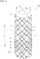
- FIG. 2 is a diagram showing the overall configuration of the stent 100.
- the stent 100 is formed by weaving a wire and has a cylindrical shape.
- the stent 100 is placed in a body lumen of a digestive system, such as a bile duct, esophagus, duodenum, small intestine, or large intestine, and is used primarily to expand and maintain the lumen.
- a digestive system such as a bile duct, esophagus, duodenum, small intestine, or large intestine
- the stent 100 of the present embodiment is not a so-called covered stent whose outer peripheral surface side is covered with a resin film or the like, but an uncovered stent which is not covered with a film or the like.
- the stent 100 can also be used as a covered stent by being covered with a resin film or the like.
- first direction A1 first direction A1
- second direction A2 second direction A2
- first circumferential direction C1 first circumferential direction C1
- second circumferential direction C2 second circumferential direction C2
- FIG. 3 is a development view of the stent 100 developed in the circumferential direction C.
- the stent 100 is formed into a circular tube shape with a mesh on the circumferential surface by a wire W extending obliquely in a circumferential direction C while repeating bending.
- the stent 100 has a plurality of straight line intersection portions 1 and a plurality of engagement portions 2.
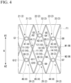
- FIG. 4 is an enlarged view of a region F1 shown in FIGS. 2 and 3 .
- the straight line intersection portion 1 is formed by straight line portions 10 of the wires W intersecting with each other in a straight line.
- the straight line portion 10 is a portion of the wire W which extends obliquely in the circumferential direction C and has a substantially straight line shape, and also includes a gently curved portion.
- the engagement portion (an intertwining portion) 2 is formed by a mountain-shaped bent portion 3 and a valley-shaped bent portion 4 intersecting with each other.
- the mountain-shaped bent portion (a mountain) 3 is a convex portion that is convex toward a side in the first direction A1, in which the wire W extending obliquely in the circumferential direction C is bent back in the longitudinal axis direction A.
- the valley-shaped bent portion (a valley) 4 is a convex portion that is convex toward a side in the second direction A2 (a concave portion that is concave toward a side in the first direction A1), in which the wire W extending obliquely in the circumferential direction C is bent back in the longitudinal axis direction A.
- the mountain-shaped bent portion 3 and the valley-shaped bent portion 4 intersect with each other in a hook shape, and thus the mountain-shaped bent portion 3 and the valley-shaped bent portion 4 are connected to each other such that they can be moved relative to each other, although they cannot be separated from each other.
- a first region E1 and a second region E2 are alternately disposed in the longitudinal axis direction A.
- the first region E1 is a region in which the plurality of straight line intersection portions 1 are arranged in the circumferential direction C.
- the second region E2 is a region in which the plurality of engagement portions 2 and one straight line intersection portion 1 are arranged in the circumferential direction C.
- the one straight line intersection portion 1 disposed in the second region E2 is provided for the wire W to move in the longitudinal axis direction A (step up and step down).
- the one straight line intersection portion 1 disposed in the second region E2 will be also referred to as a "step movement intersection portion 15." As shown in FIG. 3 , one step movement intersection portion 15 is disposed in each second region E2. A plurality of step movement intersection portions 15 are disposed at different positions in the circumferential direction C.
- the stent 100 Since the stent 100 is provided with a plurality of second regions E2 in which the plurality of engagement portions 2 are arranged in the circumferential direction C, the stent 100 has high shape followability even when curved.
- first straight line intersection portion 1A the straight line intersection portion 1A
- the first straight line portion 11 and the second straight line portion 12 intersect with each other at the first straight line intersection portion 1A.
- the first straight line portion 11 passes outside the second straight line portion 12 in the radial direction R.
- the third straight line portion 13 and the fourth straight line portion 14 intersect with each other at the second straight line intersection portion 1B.
- the third straight line portion 13 passes inside the fourth straight line portion 14 in the radial direction R.
- the first straight line intersection portion 1A and the second straight line intersection portion 1B are the straight line intersection portions 1 that are adjacent to each other in the circumferential direction C.
- the first straight line intersection portion 1A and the second straight line intersection portion 1B are disposed in the same first region E1.
- a “first mountain 31" which is the mountain-shaped bent portion 3 is continuous to a side in the first direction A1 of the first straight line portion 11.
- the first mountain 31 intersects with a first valley 41 which is the valley-shaped bent portion 4 to form a "first engagement portion 21" which is the engagement portion 2.
- the first mountain 31 and the first valley 41 intersect with each other at a first intersection portion G1 and a second intersection portion G2.
- the second intersection portion G2 is closer to the first straight line intersection portion 1A than the first intersection portion G1.
- the first mountain 31 passes outside the first valley 41 in the radial direction R.
- the first mountain 31 passes inside the first valley 41 in the radial direction R.
- a “second mountain 32" which is the mountain-shaped bent portion 3 is continuous to a side in the first direction A1 of the second straight line portion 12 and the fourth straight line portion 14.
- the second mountain 32 intersects with a second valley 42 which is the valley-shaped bent portion 4 to form a "second engagement portion 22" which is the engagement portion 2.
- the second mountain 32 and the second valley 42 intersect with each other at a third intersection portion G3 and a fourth intersection portion G4.
- the third intersection portion G3 is closer to the first straight line intersection portion 1A than the fourth intersection portion G4.
- the fourth intersection portion G4 is closer to the second straight line intersection portion 1B than the third intersection portion G3.
- the second mountain 32 passes outside the second valley 42 in the radial direction R.
- the second mountain 32 passes inside the second valley 42 in the radial direction R.
- a “third mountain 33" which is the mountain-shaped bent portion 3 is continuous to a side in the first direction A1 of the third straight line portion 13.
- the third mountain 33 intersects with a third valley 43 which is the valley-shaped bent portion 4 to form a "third engagement portion 23" which is the engagement portion 2.
- the third mountain 33 and the third valley 43 intersect with each other at a fifth intersection portion G5 and a sixth intersection portion G6.
- the fifth intersection portion G5 is closer to the second straight line intersection portion 1B than the sixth intersection portion G6.
- the third mountain 33 passes outside the third valley 43 in the radial direction R.
- the sixth intersection portion G6 the third mountain 33 passes inside the third valley 43 in the radial direction R.
- a “fourth valley 44" which is the valley-shaped bent portion 4 is continuous to a side in the second direction A2 of the fourth straight line portion 14.
- the fourth valley 44 intersects with a fourth mountain 34 which is the mountain-shaped bent portion 3 to form a "fourth engagement portion 24" which is the engagement portion 2.
- the fourth mountain 34 and the fourth valley 44 intersect with each other at a seventh intersection portion G7 and an eighth intersection portion G8.
- the eighth intersection portion G8 is closer to the second straight line intersection portion 1B than the seventh intersection portion G7.
- the fourth valley 44 passes outside the fourth mountain 34 in the radial direction R.
- the fourth valley 44 passes inside the fourth mountain 34 in the radial direction R.
- a “fifth valley 45" which is the valley-shaped bent portion 4 is continuous to a side in the second direction A2 of the first straight line portion 11 and the third straight line portion 13.
- the fifth valley 45 intersects with a fifth mountain 35 which is the mountain-shaped bent portion 3 to form a "fifth engagement portion 25" which is the engagement portion 2.
- the fifth mountain 35 and the fifth valley 45 intersect with each other at a ninth intersection portion G9 and a tenth intersection portion G10.
- the ninth intersection portion G9 is closer to the second straight line intersection portion 1B than the tenth intersection portion G10.
- the tenth intersection portion G10 is closer to the first straight line intersection portion 1A than the ninth intersection portion G9.
- the fifth valley 45 passes outside the fifth mountain 35 in the radial direction R.
- the fifth valley 45 passes inside the fifth mountain 35 in the radial direction R.
- a “sixth valley 46" which is the valley-shaped bent portion 4 is continuous to a side in the second direction A2 of the second straight line portion 12.
- the sixth valley 46 intersects with a sixth mountain 36 which is the mountain-shaped bent portion 3 to form a "sixth engagement portion 26" which is the engagement portion 2.
- the sixth mountain 36 and the sixth valley 46 intersect with each other at an eleventh intersection portion G11 and a twelfth intersection portion G12.
- the eleventh intersection portion G11 is closer to the first straight line intersection portion 1A than the twelfth intersection portion G12.
- the sixth valley 46 passes outside the sixth mountain 36 in the radial direction R.
- the sixth valley 46 passes inside the sixth mountain 36 in the radial direction R.
- the first engagement portion 21 and the second engagement portion 22 are disposed at different positions in the longitudinal axis direction A. Specifically, the second engagement portion 22 is disposed closer to a side in the first direction A1 than the first engagement portion 21 in the longitudinal axis direction A.
- the second engagement portion 22 and the third engagement portion 23 are disposed at different positions in the longitudinal axis direction A. Specifically, the third engagement portion 23 is disposed closer to a side in the second direction A2 than the second engagement portion 22 in the longitudinal axis direction A.
- the fourth engagement portion 24 and the fifth engagement portion 25 are disposed at different positions in the longitudinal axis direction A. Specifically, the fifth engagement portion 25 is disposed closer to a side in the second direction A2 than the fourth engagement portion 24 in the longitudinal axis direction A.
- the fifth engagement portion 25 and the sixth engagement portion 26 are disposed at different positions in the longitudinal axis direction A. Specifically, the sixth engagement portion 26 is disposed closer to a side in the first direction A1 than the fifth engagement portion 25 in the longitudinal axis direction A.
- the first mountain 31, the first straight line portion 11, the fifth valley 45, the third straight line portion 13, and the third mountain 33 are a continuous part (a first wire W1) of the wire W extending in a zigzag manner in the circumferential direction C.
- the sixth valley 46, the second straight line portion 12, the second mountain 32, the fourth straight line portion 14, and the fourth valley 44 are a continuous part (a second wire W2) of the wire W extending in a zigzag manner in the circumferential direction C.
- the first wire W1 and the second wire W2 may be one continuous wire or may be different wires.
- the first straight line intersection portion 1A and the second straight line intersection portion 1B which are adjacent straight line intersection portions 1, and the six engagement portions 2 (the first engagement portion 21, the second engagement portion 22, the third engagement portion 23, the fourth engagement portion 24, the fifth engagement portion 25, and the sixth engagement portion 26) which are continuous to the first straight line intersection portion 1A and the second straight line intersection portion 1B have the above-mentioned configuration.
- the engagement portions 2 continuous to other adjacent straight line intersection portions 1 in the stent 100 have the same configuration as the above-mentioned configuration, except for the portions where the step movement intersection portions 15 are provided.
- the engagement portions 2 arranged in the circumferential direction C in the second region E2 are disposed at different positions in the longitudinal axis direction A from the adjacent engagement portions 2. Specifically, the engagement portions 2 arranged in the circumferential direction C in the second region E2 are alternately disposed one by one in the longitudinal axis direction A.
- FIG. 5 is a diagram illustrating a deviation L1 and a pitch L2 of the same stent.
- a length in the longitudinal axis direction A between a position of the engagement portion 2 that is closest to a side in the first direction A1 in the second region E2 and a position of the engagement portion 2 that is closest to a side in the second direction A2 in the same second region E2 is defined as a "deviation L1."
- the position of the engagement portion 2 is a center position of the engagement portion 2 in the stent 100 that has naturally expanded into a straight line.
- a length in the longitudinal axis direction A between the second regions E2 adjacent to each other in the longitudinal axis direction A is defined as a "pitch L2."
- the length in the longitudinal axis direction A between the two second regions E2 is a distance between central axes EO of the second regions E2.
- the central axis EO is a straight line which passes through a midpoint in the longitudinal axis direction A between a position of the engagement portion 2 that is closest to a side in the first direction A1 in the second region E2 and a position of the engagement portion 2 that is closest to a side in the second direction A2 in the same second region E2, and is parallel to the circumferential direction C.
- a stent placement method using the endoscope system 300 including the stent delivery system 150 will be described using a technique for placing the stent 100 in a bile duct as an example.
- FIG. 6 is a cross-sectional view of the distal end portion of the stent delivery system 150.
- the stent 100 is accommodated in a gap between the inner tube member 120 and the outer tube member 110 in a state in which the diameter thereof is reduced in the radial direction R.
- the wires W are easily bulked up in the radial direction R more than in other portions of the stent 100 in a state in which the diameter thereof is reduced in the radial direction R.
- the engagement portions 2 are disposed in a dispersed manner in the longitudinal axis direction A, and thus the bulk of the wires W in the radial direction R can be reduced. For this reason, the stent 100 is easily accommodated in the stent delivery system.
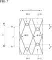
- FIG. 7 is a diagram showing the stent 100 with a large deviation L1.
- the deviation L1 be equal to or less than half the pitch L2.
- the bulk is most reduced when the deviation L1 is half the pitch L2. In a case where the deviation L1 is larger than half the pitch L2, the shape followability of the engagement portions 2 arranged in the circumferential direction C in the second region E2 will be reduced.
- the operator inserts the insertion section 210 of the endoscope 200 into the patient's body cavity through a natural opening such as the mouth. At that time, the operator operates the knob 223 and the like to curve the curving portion 212 as necessary.
- the operator passes a guide wire through the treatment instrument channel 230 of the endoscope 200 and inserts the guide wire into the bile duct while observing with the endoscope 200.
- the operator operates the guide wire under X-ray fluoroscopy to break through the narrow portion in the bile duct, and moves the distal end portion of the guide wire to the liver side from the narrow portion (a target position).
- the operator inserts the proximal end portion of the guide wire protruding from the forceps plug 225 of the endoscope 200 into a through hole of the tip 130 of the stent delivery system 150.
- the operator advances the stent delivery system 150 along the guide wire by pushing the stent delivery system 150 while holding the guidewire.
- the distal end portion of the stent delivery system 150 protrudes from the distal end portion of the treatment instrument channel 230 of the endoscope 200.
- the operator advances and retracts the stent delivery system 150 to determine the placement position of the stent 100.
- the operator may insert the stent delivery system 150 into the treatment instrument channel 230 without using the guide wire.
- the operator retracts the outer tube member 110 with respect to the inner tube member 120. As a result, as shown in FIG. 1 , the stent 100 is gradually exposed and expanded from the distal end side.
- the portion in which the engagement portion 2 is bulked up and the wires W overlap each other multiple times has a strong diameter expansion force.
- the engagement portions 2 are disposed in a dispersed manner in the longitudinal axis direction A, and thus the diameter expansion force of the engagement portions 2 can be dispersed.
- the accommodated stent has a small sliding resistance between the stent and the outer tube member 110 of the stent delivery system 150, and is therefore easily released.
- the stent 100 When stent 100 is fully exposed, the stent 100 is expanded in its entirety such that the inner diameter of the stent 100 is greater than the outer diameter of inner tube member 120. Accordingly, the engagement between the stent 100 and the inner tube member 120 is released.
- the stent 100 After the engagement between the stent 100 and the inner tube member 120 is released, when the operator retracts the inner tube member 120, the stent 100 remains in the placement position and the inner tube member 120 is removed from the stent 100.
- the engagement portion 2 in which the wires W overlap each other multiple times is provided, and the shape followability is high. Furthermore, the engagement portions 2 in which the wires W overlap each other multiple times are disposed in a dispersed manner in the longitudinal axis direction A, and thus the stent 100 is easily accommodated in the stent delivery system 150 and easily released from the stent delivery system 150.
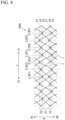
- FIG. 8 is a development view of a stent 100A that is a modification example of the stent 100.
- the stent 100A differs from the stent 100 only in the arrangement aspect of the engagement portions 2 in the second region E2.
- the engagement portions 2 arranged in the circumferential direction C in the second region E2 are disposed at one of a first position P1, a second position P2, and a third position P3 in the longitudinal axis direction A.
- the first position P1, the second position P2, and the third position P3 are arranged from a side in the first direction A1 toward a side in the second direction A2.
- the engagement portion 2 (2P1) disposed at the first position P1, the engagement portion 2 (2P2) disposed at the second position P2, and the engagement portion 2 (2P3) disposed at the third position P3 are repeatedly arranged.
- the engagement portions 2 in which the wires W overlap each other multiple times are disposed in a dispersed manner in the longitudinal axis direction A.
- the plurality of engagement portions 2 arranged in the circumferential direction C in the second region E2 may be disposed in a dispersed manner at four or more different positions in the longitudinal axis direction A.
- the engagement portion 2 on a side in the first circumferential direction C1 may be disposed on a side in the first direction A1 than a position of the engagement portion 2 on a side in the second circumferential direction C2 in the longitudinal axis direction A.
- the engagement portion 2 on a side in the first circumferential direction C1 may be disposed on a side in the second direction A2 than a position of the engagement portion 2 on a side in the second circumferential direction C2 in the longitudinal axis direction A.
- a second embodiment of the present invention will be described with reference to FIGS. 9 to 10 .
- the same constituent elements as those already described are designated by the same reference signs, and duplicate description will be omitted.
- a stent 100B according to the second embodiment is accommodated in a stent delivery system 150 similarly to the stent 100 according to the first embodiment.
- FIG. 9 is a development view of the stent 100B developed in the circumferential direction C.
- the stent 100B is formed by weaving a wire W and has a cylindrical shape similarly to the stent device 100 according to the first embodiment. Furthermore, the stent 100B has a plurality of straight line intersection portions 1 and a plurality of engagement portions 2. The stent 100B differs from the stent 100 of the first embodiment only in the arrangement of the engagement portions 2.
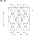
- FIG. 10 is an enlarged view of a region F2 shown in FIG. 9 .
- the first engagement portion 21 and the second engagement portion 22 are disposed at different positions in the longitudinal axis direction A. Specifically, the second engagement portion 22 is disposed closer to a side in the first direction A1 than the first engagement portion 21 in the longitudinal axis direction A.
- the second engagement portion 22 and the third engagement portion 23 are disposed at different positions in the longitudinal axis direction A. Specifically, the third engagement portion 23 is disposed closer to a side in the second direction A2 than the second engagement portion 22 in the longitudinal axis direction A.
- the fourth engagement portion 24 and the fifth engagement portion 25 are disposed at different positions in the longitudinal axis direction A. Specifically, the fifth engagement portion 25 is disposed closer to a side in the first direction A1 than the fourth engagement portion 24 in the longitudinal axis direction A.
- the fifth engagement portion 25 and the sixth engagement portion 26 are disposed at different positions in the longitudinal axis direction A. Specifically, the sixth engagement portion 26 is disposed closer to a side in the second direction A2 than the fifth engagement portion 25 in the longitudinal axis direction A.
- the engagement portion 2 in which the wires W overlap each other multiple times is provided, and the shape followability is high. Furthermore, the engagement portions 2 in which the wires W overlap each other multiple times are disposed in a dispersed manner in the longitudinal axis direction A, and thus the stent 100B is easily accommodated in the stent delivery system 150 and easily released from the stent delivery system 150.
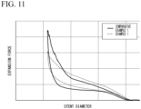
- Example 1 is the stent 100 of the above embodiment.
- Comparative Example 1 is a stent in which the deviation L 1 of the stent 100 is made zero.
- Expansion force measurement was performed using Example 1 and Comparative Example 1. The expansion force measurement was carried out on the basis of "4. Measurement of radial force" specified in JIS T3269. Reduction and expansion of the diameter of the stent placed in a bath at 37 °C are alternately and repeatedly executed for the entire stent.
- FIG. 11 shows the results of measuring the expansion force of the stent 100.
- Example 1 The expansion force of Example 1 is smaller than the expansion force of Comparative Example 1 in a state in which the diameter of the stent is most reduced.
- the engagement portions 2 are disposed in a dispersed manner in the longitudinal axis direction A, and thus the bulk of the wires W in the radial direction R can be reduced and the diameter expansion force of the engagement portions 2 can be dispersed.
- the present invention can be applied to a stent formed by weaving a wire or the like.
Landscapes
- Health & Medical Sciences (AREA)
- Engineering & Computer Science (AREA)
- Biomedical Technology (AREA)
- Life Sciences & Earth Sciences (AREA)
- Animal Behavior & Ethology (AREA)
- Veterinary Medicine (AREA)
- Public Health (AREA)
- Heart & Thoracic Surgery (AREA)
- General Health & Medical Sciences (AREA)
- Transplantation (AREA)
- Oral & Maxillofacial Surgery (AREA)
- Cardiology (AREA)
- Vascular Medicine (AREA)
- Surgery (AREA)
- Physics & Mathematics (AREA)
- Nuclear Medicine, Radiotherapy & Molecular Imaging (AREA)
- Optics & Photonics (AREA)
- Pathology (AREA)
- Radiology & Medical Imaging (AREA)
- Biophysics (AREA)
- Medical Informatics (AREA)
- Molecular Biology (AREA)
- Media Introduction/Drainage Providing Device (AREA)
Abstract
Description
- The present invention relates to a stent and a stent delivery system.
- A technique for placing a stent in a stenosis or occlusion (hereinafter referred to as a "stenosis or the like") that occurs in the gastrointestinal tract or the like and expanding it is known. A stent delivery system is used to place a stent in the stenosis or the like. The stent delivery system is inserted into a treatment instrument channel of an endoscope to deliver the stent to the stenosis or the like.
- For example, a stent described in
Patent Document 1 is formed by hooking two bending points bent in a V shape on each other, and has high shape followability even when curved. - [Patent Document 1]
Japanese Unexamined Patent Application, First Publication No. H7-265438 - However, when a stent including a portion with high shape followability, such as a form in which the bending points are hooked on each other as described in
Patent Document 1, is accommodated in a stent delivery system, the portion with high shape followability in which the wires overlap each other multiple times is easily bulked up and difficult to be accommodated therein. Since a part in which the portion with high shape followability is bulked up has a strong diameter expansion force, the accommodated stent has a large sliding resistance between the stent and the stent delivery system, and thus it is difficult to release the stent. - In view of the above circumstances, an object of the present invention is to provide a stent that has high shape followability and is easily accommodated and released, and a stent delivery system equipped with the stent.
- In order to solve the above problems, the present invention proposes the following means.
- According to a first aspect of the present invention, there is provided a stent formed by weaving a wire, including: a plurality of straight line intersection portions at which straight line portions intersect with each other; and a plurality of engagement portions at which a mountain-shaped bent portion that is bent toward a side in a first direction, which is one side in an axial direction, and becomes convex, and a valley-shaped bent portion that is bent toward a side in a second direction, which is the other side in the axial direction, and becomes convex intersect with each other, wherein the plurality of straight line intersection portions have a first straight line intersection portion at which a first straight line portion and a second straight line portion intersect with each other, and a second straight line intersection portion at which a third straight line portion and a fourth straight line portion intersect with each other, wherein the plurality of engagement portions have a first engagement portion at which a first mountain that is the mountain-shaped bent portion continuous to a side in the first direction of the first straight line portion and a first valley that is the valley-shaped bent portion intersect with each other, a second engagement portion at which a second mountain that is the mountain-shaped bent portion continuous to a side in the first direction of the second straight line portion and the fourth straight line portion and a second valley that is the valley-shaped bent portion intersect with each other, a third engagement portion at which a third mountain that is the mountain-shaped bent portion continuous to a side in the first direction of the third straight line portion and a third valley that is the valley-shaped bent portion intersect with each other, and a fifth engagement portion at which a fifth valley that is the valley-shaped bent portion continuous to a side in the second direction of the first straight line portion and the third straight line portion and a fifth mountain that is the mountain-shaped bent portion intersect with each other, wherein the first engagement portion and the second engagement portion are disposed at different positions in the axial direction, and wherein the second engagement portion and the third engagement portion are disposed at different positions in the axial direction.
- According to a second aspect of the present invention, there is provided a stent delivery system including: an operation part; an outer tube member configured to extend to a distal side from the operation part; an inner tube member configured to extend to a distal side from the operation part and located on an inside of the outer tube member; and the above-described stent which is accommodated between the outer tube member and the inner tube member, wherein the operation part is configured to place the stent by moving the outer tube member or the inner tube member in a longitudinal direction.
- The stent of the present invention has high shape followability and is easily accommodated and released.
-
-
FIG. 1 is a diagram showing the overall configuration of an endoscope system including a stent according to a first embodiment of the present invention. -
FIG. 2 is a diagram showing the overall configuration of the same stent. -
FIG. 3 is a development view of the same stent developed in a circumferential direction. -
FIG. 4 is an enlarged view of a region F1 shown inFIGS. 2 and3 . -
FIG. 5 is a diagram illustrating a deviation and a pitch of the same stent. -
FIG. 6 is a cross-sectional view of the distal end portion of a stent delivery system. -
FIG. 7 is a diagram showing the same stent with a large deviation. -
FIG. 8 is a development view of a modification example of the same stent. -
FIG. 9 is a development view of a stent according to a second embodiment of the present invention developed in the circumferential direction. -
FIG. 10 is an enlarged view of a region F2 shown inFIG. 9 . -
FIG. 11 shows the results of measuring the expansion force of the stent according to the first embodiment. - An
endoscope system 300 equipped with astent 100 according to a first embodiment of the present invention will be described with reference toFIGS. 1 to 7 .FIG. 1 is a diagram showing the overall configuration of theendoscope system 300. - The
endoscope system 300 includes anendoscope 200 and astent delivery system 150 inserted into a channel of theendoscope 200. - The
endoscope 200 is a known side-viewing flexible endoscope and includes along insertion section 210 and anoperation section 220 provided at the proximal end portion of theinsertion section 210. Theendoscope 200 may be a direct viewing flexible endoscope. - The
insertion section 210 includes a distal endrigid portion 211 provided at the distal end portion thereof, acurving portion 212 which is provided on the proximal end side of the distal endrigid portion 211 and which can be curved, and aflexible tube portion 213 provided on the proximal end side of the curvingportion 212. A light guide 215 and an imaging unit 216 having a CCD are provided on a side surface of the distal endrigid portion 211 and exposed to the outside. - A
treatment instrument channel 230 through which a treatment instrument for an endoscope such as thestent delivery system 150 is inserted is formed in theinsertion section 210. Adistal end portion 230a of thetreatment instrument channel 230 opens on the side surface of the distal endrigid portion 211. A proximal end portion of thetreatment instrument channel 230 extends to theoperation section 220. - The distal end
rigid portion 211 of thetreatment instrument channel 230 is provided with a risingbase 214. A proximal end portion of the risingbase 214 is rotatably supported by the distal endrigid portion 211. A rising base operation wire (not shown) fixed to a distal end portion of the risingbase 214 extends to the proximal end side through theinsertion section 210. - The curving
portion 212 is configured to be able to be freely curved in an updown direction and a left-right direction. A distal end of the operation wire is fixed to the distal end side of the curvingportion 212. The operation wire extends through theinsertion section 210 to theoperation section 220. - The proximal end side of the
operation section 220 is provided with aknob 223 for operating the operation wire and aswitch 224 for operating the imaging unit 216 and the like. A user can curve the curvingportion 212 in a desired direction by operating theknob 223. - A
forceps port 222 that communicates with thetreatment instrument channel 230 is provided on the distal end side of theoperation section 220. The user can insert a treatment instrument for an endoscope such as thestent delivery system 150 through theforceps port 222. Aforceps plug 225 is attached to theforceps port 222 in order to prevent leakage of a bodily fluid. - The
stent delivery system 150 is formed to be elongated as a whole and includes astent 100, anouter tube member 110, aninner tube member 120, and anoperation part 140. - The
outer tube member 110 is formed of a resin or the like, has a cylindrical shape, and has flexibility. Theouter tube member 110 can be inserted into thetreatment instrument channel 230 of theendoscope 200. - The
inner tube member 120 has an outer diameter smaller than the inner diameter of theouter tube member 110 and can pass through the internal space (the lumen) of theouter tube member 110. Theinner tube member 120 is formed of a resin or the like and has flexibility. Atip 130 having an outer diameter larger than the outer diameter of theouter tube member 110 is provided at the distal end of theinner tube member 120. - The
stent 100 is accommodated in the distal end portion of thestent delivery system 150, as shown inFIG. 1 . Thestent 100 is accommodated in a gap between theinner tube member 120 and theouter tube member 110 in a state in which theinner tube member 120 is passed therethrough and the diameter thereof is reduced. - The
operation part 140 is connected to the proximal end sides of theouter tube member 110 and theinner tube member 120, and is configured to be able to move theouter tube member 110 relative to theinner tube member 120 in a longitudinal direction. By operating theoperation part 140, the operator moves theouter tube member 110 relative to theinner tube member 120 to expose the accommodatedstent 100, and as a result, thestent 100 can be placed. Furthermore, when thestent 100 has been exposed, the operator can re-accommodate thestent 100 by operating theouter tube member 110 to move relative to theinner tube member 120 in an opposite direction. -
FIG. 2 is a diagram showing the overall configuration of thestent 100. - The
stent 100 is formed by weaving a wire and has a cylindrical shape. Thestent 100 is placed in a body lumen of a digestive system, such as a bile duct, esophagus, duodenum, small intestine, or large intestine, and is used primarily to expand and maintain the lumen. - The
stent 100 of the present embodiment is not a so-called covered stent whose outer peripheral surface side is covered with a resin film or the like, but an uncovered stent which is not covered with a film or the like. However, thestent 100 can also be used as a covered stent by being covered with a resin film or the like. - In the following description, one side in a longitudinal axis direction (an axial direction) A of the
stent 100 will be referred to as a "first direction A1," and the other side in the longitudinal axis direction A of thestent 100 will be referred to as a "second direction A2." Further, one side in a circumferential directions C of thestent 100 will be referred to as a "first circumferential direction C1," and the other side in the circumferential direction C of thestent 100 will be referred to as a "second circumferential direction C2." -
FIG. 3 is a development view of thestent 100 developed in the circumferential direction C. - The
stent 100 is formed into a circular tube shape with a mesh on the circumferential surface by a wire W extending obliquely in a circumferential direction C while repeating bending. Thestent 100 has a plurality of straightline intersection portions 1 and a plurality ofengagement portions 2. -
FIG. 4 is an enlarged view of a region F1 shown inFIGS. 2 and3 . - The straight
line intersection portion 1 is formed bystraight line portions 10 of the wires W intersecting with each other in a straight line. Thestraight line portion 10 is a portion of the wire W which extends obliquely in the circumferential direction C and has a substantially straight line shape, and also includes a gently curved portion. - The engagement portion (an intertwining portion) 2 is formed by a mountain-shaped
bent portion 3 and a valley-shapedbent portion 4 intersecting with each other. The mountain-shaped bent portion (a mountain) 3 is a convex portion that is convex toward a side in the first direction A1, in which the wire W extending obliquely in the circumferential direction C is bent back in the longitudinal axis direction A. The valley-shaped bent portion (a valley) 4 is a convex portion that is convex toward a side in the second direction A2 (a concave portion that is concave toward a side in the first direction A1), in which the wire W extending obliquely in the circumferential direction C is bent back in the longitudinal axis direction A. At theengagement portion 2, the mountain-shapedbent portion 3 and the valley-shapedbent portion 4 intersect with each other in a hook shape, and thus the mountain-shapedbent portion 3 and the valley-shapedbent portion 4 are connected to each other such that they can be moved relative to each other, although they cannot be separated from each other. - As shown in
FIGS. 2 and3 , a first region E1 and a second region E2 are alternately disposed in the longitudinal axis direction A. The first region E1 is a region in which the plurality of straightline intersection portions 1 are arranged in the circumferential direction C. Further, the second region E2 is a region in which the plurality ofengagement portions 2 and one straightline intersection portion 1 are arranged in the circumferential direction C. The one straightline intersection portion 1 disposed in the second region E2 is provided for the wire W to move in the longitudinal axis direction A (step up and step down). - In the following description, the one straight
line intersection portion 1 disposed in the second region E2 will be also referred to as a "stepmovement intersection portion 15." As shown inFIG. 3 , one stepmovement intersection portion 15 is disposed in each second region E2. A plurality of stepmovement intersection portions 15 are disposed at different positions in the circumferential direction C. - Since the
stent 100 is provided with a plurality of second regions E2 in which the plurality ofengagement portions 2 are arranged in the circumferential direction C, thestent 100 has high shape followability even when curved. - As shown in
FIG. 4 , a firststraight line portion 11 and a secondstraight line portion 12, which are thestraight line portions 10, intersect with each other at a "first straightline intersection portion 1A" that is the straightline intersection portion 1. Specifically, when viewed in a radial direction R of the stent 100 (seeFIG. 2 ), the firststraight line portion 11 and the secondstraight line portion 12 intersect with each other at the first straightline intersection portion 1A. At the first straightline intersection portion 1A, the firststraight line portion 11 passes outside the secondstraight line portion 12 in the radial direction R. - As shown in
FIG. 4 , a thirdstraight line portion 13 and a fourthstraight line portion 14, which are thestraight line portions 10, intersect with each other at a "second straightline intersection portion 1B" that is the straightline intersection portion 1. Specifically, when viewed in the radial direction R of the stent 100 (seeFIG. 2 ), the thirdstraight line portion 13 and the fourthstraight line portion 14 intersect with each other at the second straightline intersection portion 1B. At the second straightline intersection portion 1B, the thirdstraight line portion 13 passes inside the fourthstraight line portion 14 in the radial direction R. - The first straight
line intersection portion 1A and the second straightline intersection portion 1B are the straightline intersection portions 1 that are adjacent to each other in the circumferential direction C. The first straightline intersection portion 1A and the second straightline intersection portion 1B are disposed in the same first region E1. - A "
first mountain 31" which is the mountain-shapedbent portion 3 is continuous to a side in the first direction A1 of the firststraight line portion 11. Thefirst mountain 31 intersects with afirst valley 41 which is the valley-shapedbent portion 4 to form a "first engagement portion 21" which is theengagement portion 2. - Specifically, when viewed in the radial direction R of the
stent 100, thefirst mountain 31 and thefirst valley 41 intersect with each other at a first intersection portion G1 and a second intersection portion G2. The second intersection portion G2 is closer to the first straightline intersection portion 1A than the first intersection portion G1. At the first intersection portion G1, thefirst mountain 31 passes outside thefirst valley 41 in the radial direction R. At the second intersection portion G2, thefirst mountain 31 passes inside thefirst valley 41 in the radial direction R. - A "
second mountain 32" which is the mountain-shapedbent portion 3 is continuous to a side in the first direction A1 of the secondstraight line portion 12 and the fourthstraight line portion 14. Thesecond mountain 32 intersects with asecond valley 42 which is the valley-shapedbent portion 4 to form a "second engagement portion 22" which is theengagement portion 2. - Specifically, when viewed in the radial direction R of the
stent 100, thesecond mountain 32 and thesecond valley 42 intersect with each other at a third intersection portion G3 and a fourth intersection portion G4. The third intersection portion G3 is closer to the first straightline intersection portion 1A than the fourth intersection portion G4. The fourth intersection portion G4 is closer to the second straightline intersection portion 1B than the third intersection portion G3. At the third intersection portion G3, thesecond mountain 32 passes outside thesecond valley 42 in the radial direction R. At the fourth intersection portion G4, thesecond mountain 32 passes inside thesecond valley 42 in the radial direction R. - A "
third mountain 33" which is the mountain-shapedbent portion 3 is continuous to a side in the first direction A1 of the thirdstraight line portion 13. Thethird mountain 33 intersects with athird valley 43 which is the valley-shapedbent portion 4 to form a "third engagement portion 23" which is theengagement portion 2. - Specifically, when viewed in the radial direction R of the
stent 100, thethird mountain 33 and thethird valley 43 intersect with each other at a fifth intersection portion G5 and a sixth intersection portion G6. The fifth intersection portion G5 is closer to the second straightline intersection portion 1B than the sixth intersection portion G6. At the fifth intersection portion G5, thethird mountain 33 passes outside thethird valley 43 in the radial direction R. At the sixth intersection portion G6, thethird mountain 33 passes inside thethird valley 43 in the radial direction R. - A "
fourth valley 44" which is the valley-shapedbent portion 4 is continuous to a side in the second direction A2 of the fourthstraight line portion 14. Thefourth valley 44 intersects with afourth mountain 34 which is the mountain-shapedbent portion 3 to form a "fourth engagement portion 24" which is theengagement portion 2. - Specifically, when viewed in the radial direction R of the
stent 100, thefourth mountain 34 and thefourth valley 44 intersect with each other at a seventh intersection portion G7 and an eighth intersection portion G8. The eighth intersection portion G8 is closer to the second straightline intersection portion 1B than the seventh intersection portion G7. At the seventh intersection portion G7, thefourth valley 44 passes outside thefourth mountain 34 in the radial direction R. At the eighth intersection portion G8, thefourth valley 44 passes inside thefourth mountain 34 in the radial direction R. - A "
fifth valley 45" which is the valley-shapedbent portion 4 is continuous to a side in the second direction A2 of the firststraight line portion 11 and the thirdstraight line portion 13. Thefifth valley 45 intersects with afifth mountain 35 which is the mountain-shapedbent portion 3 to form a "fifth engagement portion 25" which is theengagement portion 2. - Specifically, when viewed in the radial direction R of the
stent 100, thefifth mountain 35 and thefifth valley 45 intersect with each other at a ninth intersection portion G9 and a tenth intersection portion G10. The ninth intersection portion G9 is closer to the second straightline intersection portion 1B than the tenth intersection portion G10. The tenth intersection portion G10 is closer to the first straightline intersection portion 1A than the ninth intersection portion G9. At the ninth intersection portion G9, thefifth valley 45 passes outside thefifth mountain 35 in the radial direction R. At the tenth intersection portion G10, thefifth valley 45 passes inside thefifth mountain 35 in the radial direction R. - A "
sixth valley 46" which is the valley-shapedbent portion 4 is continuous to a side in the second direction A2 of the secondstraight line portion 12. Thesixth valley 46 intersects with asixth mountain 36 which is the mountain-shapedbent portion 3 to form a "sixth engagement portion 26" which is theengagement portion 2. - Specifically, when viewed in the radial direction R of the
stent 100, thesixth mountain 36 and thesixth valley 46 intersect with each other at an eleventh intersection portion G11 and a twelfth intersection portion G12. The eleventh intersection portion G11 is closer to the first straightline intersection portion 1A than the twelfth intersection portion G12. At the eleventh intersection portion G11, thesixth valley 46 passes outside thesixth mountain 36 in the radial direction R. At the twelfth intersection portion G12, thesixth valley 46 passes inside thesixth mountain 36 in the radial direction R. - The
first engagement portion 21 and thesecond engagement portion 22 are disposed at different positions in the longitudinal axis direction A. Specifically, thesecond engagement portion 22 is disposed closer to a side in the first direction A1 than thefirst engagement portion 21 in the longitudinal axis direction A. - The
second engagement portion 22 and thethird engagement portion 23 are disposed at different positions in the longitudinal axis direction A. Specifically, thethird engagement portion 23 is disposed closer to a side in the second direction A2 than thesecond engagement portion 22 in the longitudinal axis direction A. - The
fourth engagement portion 24 and thefifth engagement portion 25 are disposed at different positions in the longitudinal axis direction A. Specifically, thefifth engagement portion 25 is disposed closer to a side in the second direction A2 than thefourth engagement portion 24 in the longitudinal axis direction A. - The
fifth engagement portion 25 and thesixth engagement portion 26 are disposed at different positions in the longitudinal axis direction A. Specifically, thesixth engagement portion 26 is disposed closer to a side in the first direction A1 than thefifth engagement portion 25 in the longitudinal axis direction A. - The
first mountain 31, the firststraight line portion 11, thefifth valley 45, the thirdstraight line portion 13, and thethird mountain 33 are a continuous part (a first wire W1) of the wire W extending in a zigzag manner in the circumferential direction C. Further, thesixth valley 46, the secondstraight line portion 12, thesecond mountain 32, the fourthstraight line portion 14, and thefourth valley 44 are a continuous part (a second wire W2) of the wire W extending in a zigzag manner in the circumferential direction C. The first wire W1 and the second wire W2 may be one continuous wire or may be different wires. - The first straight
line intersection portion 1A and the second straightline intersection portion 1B which are adjacent straightline intersection portions 1, and the six engagement portions 2 (thefirst engagement portion 21, thesecond engagement portion 22, thethird engagement portion 23, thefourth engagement portion 24, thefifth engagement portion 25, and the sixth engagement portion 26) which are continuous to the first straightline intersection portion 1A and the second straightline intersection portion 1B have the above-mentioned configuration. As shown inFIG. 3 , theengagement portions 2 continuous to other adjacent straightline intersection portions 1 in thestent 100 have the same configuration as the above-mentioned configuration, except for the portions where the stepmovement intersection portions 15 are provided. - As shown in
FIG. 3 , theengagement portions 2 arranged in the circumferential direction C in the second region E2 are disposed at different positions in the longitudinal axis direction A from theadjacent engagement portions 2. Specifically, theengagement portions 2 arranged in the circumferential direction C in the second region E2 are alternately disposed one by one in the longitudinal axis direction A. -
FIG. 5 is a diagram illustrating a deviation L1 and a pitch L2 of the same stent. - A length in the longitudinal axis direction A between a position of the
engagement portion 2 that is closest to a side in the first direction A1 in the second region E2 and a position of theengagement portion 2 that is closest to a side in the second direction A2 in the same second region E2 is defined as a "deviation L1." Here, the position of theengagement portion 2 is a center position of theengagement portion 2 in thestent 100 that has naturally expanded into a straight line. - A length in the longitudinal axis direction A between the second regions E2 adjacent to each other in the longitudinal axis direction A is defined as a "pitch L2." Here, the length in the longitudinal axis direction A between the two second regions E2 is a distance between central axes EO of the second regions E2. The central axis EO is a straight line which passes through a midpoint in the longitudinal axis direction A between a position of the
engagement portion 2 that is closest to a side in the first direction A1 in the second region E2 and a position of theengagement portion 2 that is closest to a side in the second direction A2 in the same second region E2, and is parallel to the circumferential direction C. - A stent placement method using the
endoscope system 300 including thestent delivery system 150 will be described using a technique for placing thestent 100 in a bile duct as an example. -
FIG. 6 is a cross-sectional view of the distal end portion of thestent delivery system 150. - The
stent 100 is accommodated in a gap between theinner tube member 120 and theouter tube member 110 in a state in which the diameter thereof is reduced in the radial direction R. In theengagement portion 2 in which the wires W overlap each other multiple times, the wires W are easily bulked up in the radial direction R more than in other portions of thestent 100 in a state in which the diameter thereof is reduced in the radial direction R. However, in thestent 100, in the second region E2, theengagement portions 2 are disposed in a dispersed manner in the longitudinal axis direction A, and thus the bulk of the wires W in the radial direction R can be reduced. For this reason, thestent 100 is easily accommodated in the stent delivery system. -
FIG. 7 is a diagram showing thestent 100 with a large deviation L1. - The larger the deviation L1 is, the more the
stent 100 can suitably reduce the bulk of the wires W in the radial direction R in a state in which the diameter thereof is reduced in the radial direction R as shown inFIG. 6 . Here, it is desirable that the deviation L1 be equal to or less than half the pitch L2. The bulk is most reduced when the deviation L1 is half the pitch L2. In a case where the deviation L1 is larger than half the pitch L2, the shape followability of theengagement portions 2 arranged in the circumferential direction C in the second region E2 will be reduced. - The operator inserts the
insertion section 210 of theendoscope 200 into the patient's body cavity through a natural opening such as the mouth. At that time, the operator operates theknob 223 and the like to curve the curvingportion 212 as necessary. - The operator passes a guide wire through the
treatment instrument channel 230 of theendoscope 200 and inserts the guide wire into the bile duct while observing with theendoscope 200. Next, the operator operates the guide wire under X-ray fluoroscopy to break through the narrow portion in the bile duct, and moves the distal end portion of the guide wire to the liver side from the narrow portion (a target position). - The operator inserts the proximal end portion of the guide wire protruding from the forceps plug 225 of the
endoscope 200 into a through hole of thetip 130 of thestent delivery system 150. - The operator advances the
stent delivery system 150 along the guide wire by pushing thestent delivery system 150 while holding the guidewire. The distal end portion of thestent delivery system 150 protrudes from the distal end portion of thetreatment instrument channel 230 of theendoscope 200. When the distal end portion of thestent delivery system 150 breaks through the narrow portion (the target position), the operator advances and retracts thestent delivery system 150 to determine the placement position of thestent 100. The operator may insert thestent delivery system 150 into thetreatment instrument channel 230 without using the guide wire. - After the target position of the
stent 100 is determined, the operator retracts theouter tube member 110 with respect to theinner tube member 120. As a result, as shown inFIG. 1 , thestent 100 is gradually exposed and expanded from the distal end side. - In the state in which the diameter of the stent is reduced in the radial direction R, the portion in which the
engagement portion 2 is bulked up and the wires W overlap each other multiple times has a strong diameter expansion force. However, in thestent 100, in the second region E2, theengagement portions 2 are disposed in a dispersed manner in the longitudinal axis direction A, and thus the diameter expansion force of theengagement portions 2 can be dispersed. For this reason, the accommodated stent has a small sliding resistance between the stent and theouter tube member 110 of thestent delivery system 150, and is therefore easily released. - When
stent 100 is fully exposed, thestent 100 is expanded in its entirety such that the inner diameter of thestent 100 is greater than the outer diameter ofinner tube member 120. Accordingly, the engagement between thestent 100 and theinner tube member 120 is released. - After the engagement between the
stent 100 and theinner tube member 120 is released, when the operator retracts theinner tube member 120, thestent 100 remains in the placement position and theinner tube member 120 is removed from thestent 100. - When the operator pulls out the
stent delivery system 150 except for thestent 100 from the body, the procedure for placing thestent 100 is completed. - According to the
stent 100 of the present embodiment, theengagement portion 2 in which the wires W overlap each other multiple times is provided, and the shape followability is high. Furthermore, theengagement portions 2 in which the wires W overlap each other multiple times are disposed in a dispersed manner in the longitudinal axis direction A, and thus thestent 100 is easily accommodated in thestent delivery system 150 and easily released from thestent delivery system 150. - In the above, the first embodiment of the present invention has been described in detail with reference to the drawings, but the specific configuration is not limited to the embodiment, and a design change and the like within a range not departing from the gist of the present invention are also included. The constituent elements shown in the above-described embodiment and a modification example shown below can be appropriately combined and configured.
- In the embodiment described above, the
engagement portions 2 arranged in the circumferential direction C in the second region E2 are alternately disposed one by one in the longitudinal axis direction A. However, the arrangement aspect of theengagement portions 2 in the second region E2 is not limited to this.FIG. 8 is a development view of astent 100A that is a modification example of thestent 100. Thestent 100A differs from thestent 100 only in the arrangement aspect of theengagement portions 2 in the second region E2. - In the
stent 100A, theengagement portions 2 arranged in the circumferential direction C in the second region E2 are disposed at one of a first position P1, a second position P2, and a third position P3 in the longitudinal axis direction A. The first position P1, the second position P2, and the third position P3 are arranged from a side in the first direction A1 toward a side in the second direction A2. - From a side in a first circumferential direction C1 toward a side in a second circumferential direction C2, the engagement portion 2 (2P1) disposed at the first position P1, the engagement portion 2 (2P2) disposed at the second position P2, and the engagement portion 2 (2P3) disposed at the third position P3 are repeatedly arranged. In the
stent 100A, theengagement portions 2 in which the wires W overlap each other multiple times are disposed in a dispersed manner in the longitudinal axis direction A. - The plurality of
engagement portions 2 arranged in the circumferential direction C in the second region E2 may be disposed in a dispersed manner at four or more different positions in the longitudinal axis direction A. In theengagement portions 2 adjacent to each other in the circumferential direction C in the second region E2, theengagement portion 2 on a side in the first circumferential direction C1 may be disposed on a side in the first direction A1 than a position of theengagement portion 2 on a side in the second circumferential direction C2 in the longitudinal axis direction A. Alternately, theengagement portion 2 on a side in the first circumferential direction C1 may be disposed on a side in the second direction A2 than a position of theengagement portion 2 on a side in the second circumferential direction C2 in the longitudinal axis direction A. - A second embodiment of the present invention will be described with reference to
FIGS. 9 to 10 . In the following description, the same constituent elements as those already described are designated by the same reference signs, and duplicate description will be omitted. Astent 100B according to the second embodiment is accommodated in astent delivery system 150 similarly to thestent 100 according to the first embodiment. -
FIG. 9 is a development view of thestent 100B developed in the circumferential direction C. - The
stent 100B is formed by weaving a wire W and has a cylindrical shape similarly to thestent device 100 according to the first embodiment. Furthermore, thestent 100B has a plurality of straightline intersection portions 1 and a plurality ofengagement portions 2. Thestent 100B differs from thestent 100 of the first embodiment only in the arrangement of theengagement portions 2. -
FIG. 10 is an enlarged view of a region F2 shown inFIG. 9 . - The
first engagement portion 21 and thesecond engagement portion 22 are disposed at different positions in the longitudinal axis direction A. Specifically, thesecond engagement portion 22 is disposed closer to a side in the first direction A1 than thefirst engagement portion 21 in the longitudinal axis direction A. - The
second engagement portion 22 and thethird engagement portion 23 are disposed at different positions in the longitudinal axis direction A. Specifically, thethird engagement portion 23 is disposed closer to a side in the second direction A2 than thesecond engagement portion 22 in the longitudinal axis direction A. - The
fourth engagement portion 24 and thefifth engagement portion 25 are disposed at different positions in the longitudinal axis direction A. Specifically, thefifth engagement portion 25 is disposed closer to a side in the first direction A1 than thefourth engagement portion 24 in the longitudinal axis direction A. - The
fifth engagement portion 25 and thesixth engagement portion 26 are disposed at different positions in the longitudinal axis direction A. Specifically, thesixth engagement portion 26 is disposed closer to a side in the second direction A2 than thefifth engagement portion 25 in the longitudinal axis direction A. - According to the
stent 100B of the present embodiment, theengagement portion 2 in which the wires W overlap each other multiple times is provided, and the shape followability is high. Furthermore, theengagement portions 2 in which the wires W overlap each other multiple times are disposed in a dispersed manner in the longitudinal axis direction A, and thus thestent 100B is easily accommodated in thestent delivery system 150 and easily released from thestent delivery system 150. - In the above, the second embodiment of the present invention has been described in detail with reference to the drawings, but the specific configuration is not limited to the embodiment, and a design change and the like within a range not departing from the gist of the present invention are also included. The constituent elements shown in the above-described embodiment and a modification example can be appropriately combined and configured.
- Hereinafter, the present invention will be explained in detail on the basis of Examples, but the technical scope of the present invention is not limited to these Examples.
- Example 1 is the
stent 100 of the above embodiment. - Comparative Example 1 is a stent in which the
deviation L 1 of thestent 100 is made zero. - Expansion force measurement was performed using Example 1 and Comparative Example 1. The expansion force measurement was carried out on the basis of "4. Measurement of radial force" specified in JIS T3269. Reduction and expansion of the diameter of the stent placed in a bath at 37 °C are alternately and repeatedly executed for the entire stent.
-
FIG. 11 shows the results of measuring the expansion force of thestent 100. - The expansion force of Example 1 is smaller than the expansion force of Comparative Example 1 in a state in which the diameter of the stent is most reduced. In Example 1, in the second region E2, the
engagement portions 2 are disposed in a dispersed manner in the longitudinal axis direction A, and thus the bulk of the wires W in the radial direction R can be reduced and the diameter expansion force of theengagement portions 2 can be dispersed. - On the other hand, in the process of diameter reduction and diameter expansion, there is little difference between the expansion force of Example 1 and the expansion force of Comparative Example 1. That is, even in a case where the
stent 100 is provided with the deviation L1 as in Example 1, the basic function of the stent, which is to widen the stenosis or occlusion, can be maintained. - The present invention can be applied to a stent formed by weaving a wire or the like.
-
- 300 Endoscope system
- 200 Endoscope
- 150 Stent delivery system
- 110 Outer tube member
- 120 Inner tube member
- 130 Tip
- 100, 100A, 100B Stent
- 1 Straight line intersection portion
- 10 Straight line portion
- 11 First straight line portion
- 12 Second straight line portion
- 13 Third straight line portion
- 14 Fourth straight line portion
- 15 Step movement intersection portion
- 1A First straight line intersection portion
- 1B Second straight line intersection portion
- 2 Engagement portion (intertwining portion)
- 21 First engagement portion
- 22 Second engagement portion
- 23 Third engagement portion
- 24 Fourth engagement portion
- 25 Fifth engagement portion
- 26 Sixth engagement portion
- 3 Mountain-shaped bent portion (mountain)
- 31 First mountain
- 32 Second mountain
- 33 Third mountain
- 34 Fourth mountain
- 35 Fifth mountain
- 36 Sixth mountain
- 4 Valley-shaped bent portion (valley)
- 41 First Valley
- 42 Second valley
- 43 Third Valley
- 44 Fourth Valley
- 45 Fifth valley
- 46 Sixth Valley
Claims (11)
- A stent formed by weaving a wire, comprising:a plurality of straight line intersection portions at which straight line portions intersect with each other; anda plurality of engagement portions at which a mountain-shaped bent portion that is bent toward a side in a first direction, which is one side in an axial direction, and becomes convex, and a valley-shaped bent portion that is bent toward a side in a second direction, which is the other side in the axial direction, and becomes convex intersect with each other,wherein the plurality of straight line intersection portions havea first straight line intersection portion at which a first straight line portion and a second straight line portion intersect with each other, anda second straight line intersection portion at which a third straight line portion and a fourth straight line portion intersect with each other,wherein the plurality of engagement portions havea first engagement portion at which a first mountain that is the mountain-shaped bent portion continuous to a side in the first direction of the first straight line portion and a first valley that is the valley-shaped bent portion intersect with each other,a second engagement portion at which a second mountain that is the mountain-shaped bent portion continuous to a side in the first direction of the second straight line portion and the fourth straight line portion and a second valley that is the valley-shaped bent portion intersect with each other,a third engagement portion at which a third mountain that is the mountain-shaped bent portion continuous to a side in the first direction of the third straight line portion and a third valley that is the valley-shaped bent portion intersect with each other, anda fifth engagement portion at which a fifth valley that is the valley-shaped bent portion continuous to a side in the second direction of the first straight line portion and the third straight line portion and a fifth mountain that is the mountain-shaped bent portion intersect with each other,wherein the first engagement portion and the second engagement portion are disposed at different positions in the axial direction, andwherein the second engagement portion and the third engagement portion are disposed at different positions in the axial direction.
- The stent according to claim 1,wherein the second engagement portion is disposed closer to a side in the first direction than the first engagement portion in the axial direction, andwherein the third engagement portion is disposed closer to a side in the second direction than the second engagement portion in the axial direction.
- The stent according to claim 1, wherein a first region in which the plurality of straight line intersection portions are disposed in a circumferential direction and a second region in which the plurality of engagement portions and one straight line intersection portion are disposed in the circumferential direction are disposed alternately in the axial direction.
- The stent according to claim 3, wherein the straight line intersection portions disposed in the second regions are disposed at different positions in the circumferential direction.
- The stent according to claim 3, wherein a length in the axial direction between a position of the engagement portion that is closest to a side in the first direction in the second region and a position of the engagement portion that is closest to a side in the second direction in the same second region is equal to or less than half a length in the axial direction between the second regions adjacent to each other in the axial direction.
- The stent according to claim 1,wherein the plurality of engagement portions further includea fourth engagement portion at which a fourth valley that is the valley-shaped bent portion continuous to a side in the second direction of the fourth straight line portion and a fourth mountain that is the mountain-shaped bent portion intersect with each other, anda sixth engagement portion at which a sixth valley that is the valley-shaped bent portion continuous to a side in the second direction of the second straight line portion and a sixth mountain that is the mountain-shaped bent portion intersect with each other,wherein the fourth engagement portion and the fifth engagement portion are disposed at different positions in the axial direction, andwherein the fifth engagement portion and the sixth engagement portion are disposed at different positions in the axial direction.
- The stent according to claim 6,wherein the second engagement portion is disposed closer to a side in the first direction than the first engagement portion in the axial direction,wherein the third engagement portion is disposed closer to a side in the second direction than the second engagement portion in the axial direction,wherein the fifth engagement portion is disposed closer to a side in the second direction than the fourth engagement portion in the axial direction, andwherein the sixth engagement portion is disposed closer to a side in the first direction than the fifth engagement portion in the axial direction.
- The stent according to claim 6,wherein the second engagement portion is disposed closer to a side in the first direction than the first engagement portion in the axial direction,wherein the third engagement portion is disposed closer to a side in the first direction than the second engagement portion in the axial direction,wherein the fifth engagement portion is disposed closer to a side in the first direction than the fourth engagement portion in the axial direction, andwherein the sixth engagement portion is disposed closer to a side in the first direction than the fifth engagement portion in the axial direction.
- The stent according to claim 6,wherein the second engagement portion is disposed closer to a side in the first direction than the first engagement portion in the axial direction,wherein the third engagement portion is disposed closer to a side in the second direction than the second engagement portion in the axial direction,wherein the fifth engagement portion is disposed closer to a side in the first direction than the fourth engagement portion in the axial direction, andwherein the sixth engagement portion is disposed closer to a side in the second direction than the fifth engagement portion in the axial direction.
- A stent delivery system comprising:an operation part;an outer tube member configured to extend to a distal side from the operation part;an inner tube member configured to extend to a distal side from the operation part and located on an inside of the outer tube member; andthe stent according to any one of claims 1 to 9 which is accommodated between the outer tube member and the inner tube member,wherein the operation part is configured to place the stent by moving the outer tube member or the inner tube member in a longitudinal direction.
- The stent delivery system according to claim 10, wherein the outer tube member is configured to be able to be inserted into a channel of an endoscope.
Applications Claiming Priority (1)
| Application Number | Priority Date | Filing Date | Title |
|---|---|---|---|
| PCT/JP2021/034669 WO2023047477A1 (en) | 2021-09-22 | 2021-09-22 | Stent and stent delivery system |
Publications (2)
| Publication Number | Publication Date |
|---|---|
| EP4406517A1 true EP4406517A1 (en) | 2024-07-31 |
| EP4406517A4 EP4406517A4 (en) | 2025-07-16 |
Family
ID=85720285
Family Applications (1)
| Application Number | Title | Priority Date | Filing Date |
|---|---|---|---|
| EP21958354.9A Withdrawn EP4406517A4 (en) | 2021-09-22 | 2021-09-22 | STENT AND STEN DELIVERY SYSTEM |
Country Status (6)
| Country | Link |
|---|---|
| US (1) | US20240245539A1 (en) |
| EP (1) | EP4406517A4 (en) |
| JP (1) | JP7612885B2 (en) |
| KR (1) | KR20240033284A (en) |
| CN (1) | CN117999050A (en) |
| WO (1) | WO2023047477A1 (en) |
Family Cites Families (7)
| Publication number | Priority date | Publication date | Assignee | Title |
|---|---|---|---|---|
| KR970004845Y1 (en) | 1993-09-27 | 1997-05-21 | 주식회사 수호메디테크 | Endoscopic expansion medical equipment |
| DE69927055T2 (en) * | 1998-12-11 | 2006-06-29 | Endologix, Inc., Irvine | ENDOLUMINAL VASCULAR PROSTHESIS |
| KR100824074B1 (en) * | 2007-04-24 | 2008-04-21 | 주식회사 엠아이텍 | Stent |
| KR101785042B1 (en) * | 2016-02-15 | 2017-10-12 | (주) 태웅메디칼 | A jig for the manufacture of the stent and which are manufactured with the manufacturing method whereby the stent using a shape memory alloy wire |
| CN108013955B (en) * | 2016-11-04 | 2020-01-10 | 先健科技(深圳)有限公司 | Blood vessel support |
| WO2021166156A1 (en) * | 2020-02-20 | 2021-08-26 | オリンパス株式会社 | Stent delivery system, endoscope system, and stenting method |
| CN113133856B (en) * | 2021-04-20 | 2022-12-13 | 北京弘海微创科技有限公司 | Z-shaped woven support |
-
2021
- 2021-09-22 JP JP2023549209A patent/JP7612885B2/en active Active
- 2021-09-22 CN CN202180102419.6A patent/CN117999050A/en active Pending
- 2021-09-22 KR KR1020247006278A patent/KR20240033284A/en not_active Ceased
- 2021-09-22 EP EP21958354.9A patent/EP4406517A4/en not_active Withdrawn
- 2021-09-22 WO PCT/JP2021/034669 patent/WO2023047477A1/en not_active Ceased
-
2024
- 2024-03-06 US US18/596,880 patent/US20240245539A1/en active Pending
Also Published As
| Publication number | Publication date |
|---|---|
| KR20240033284A (en) | 2024-03-12 |
| JPWO2023047477A1 (en) | 2023-03-30 |
| WO2023047477A1 (en) | 2023-03-30 |
| CN117999050A (en) | 2024-05-07 |
| JP7612885B2 (en) | 2025-01-14 |
| EP4406517A4 (en) | 2025-07-16 |
| US20240245539A1 (en) | 2024-07-25 |
Similar Documents
| Publication | Publication Date | Title |
|---|---|---|
| EP3138465A1 (en) | Endoscope bending tube and endoscope provided with endoscope bending tube | |
| CN102939042B (en) | biliary access sheath | |
| EP2638870B1 (en) | Endoscopic treatment instrument | |
| US20170232237A1 (en) | Medical instrument and medical system | |
| US11701498B2 (en) | Guide wire gripping unit | |
| JPWO2010082399A1 (en) | Endoscopic treatment tool | |
| CN115697222B (en) | expander | |
| CN111249044A (en) | Support and imbedding system | |
| US20250114576A1 (en) | Guide wire holder | |
| KR20160138004A (en) | Stent delivery system and endoscope system | |
| EP4397283A1 (en) | Stent and stent delivery system | |
| US20240189125A1 (en) | Stent device and stent delivery system | |
| US20260013979A1 (en) | Stent device | |
| EP4406517A1 (en) | Stent and stent delivery system | |
| US20130197310A1 (en) | Intracorporeal insertion instrument | |
| WO2018047340A1 (en) | Medical instrument and medical system | |
| CN119074136B (en) | Foreign body removal device | |
| US12589015B2 (en) | Stent delivery system, endoscope system, and stent indwelling method | |
| JP2026027746A (en) | stents | |
| US20240139008A1 (en) | Catheter and delivery system | |
| JP2705701B2 (en) | Endoscope system | |
| CN118843438A (en) | Catheter and delivery system | |
| WO2022249413A1 (en) | Catheter | |
| JPH01285238A (en) | Flexible tube of endoscope |
Legal Events
| Date | Code | Title | Description |
|---|---|---|---|
| STAA | Information on the status of an ep patent application or granted ep patent |
Free format text: STATUS: THE INTERNATIONAL PUBLICATION HAS BEEN MADE |
|
| PUAI | Public reference made under article 153(3) epc to a published international application that has entered the european phase |
Free format text: ORIGINAL CODE: 0009012 |
|
| STAA | Information on the status of an ep patent application or granted ep patent |
Free format text: STATUS: REQUEST FOR EXAMINATION WAS MADE |
|
| 17P | Request for examination filed |
Effective date: 20240312 |
|
| AK | Designated contracting states |
Kind code of ref document: A1 Designated state(s): AL AT BE BG CH CY CZ DE DK EE ES FI FR GB GR HR HU IE IS IT LI LT LU LV MC MK MT NL NO PL PT RO RS SE SI SK SM TR |
|
| DAV | Request for validation of the european patent (deleted) | ||
| DAX | Request for extension of the european patent (deleted) | ||
| STAA | Information on the status of an ep patent application or granted ep patent |
Free format text: STATUS: EXAMINATION IS IN PROGRESS |
|
| A4 | Supplementary search report drawn up and despatched |
Effective date: 20250618 |
|
| RIC1 | Information provided on ipc code assigned before grant |
Ipc: A61F 2/90 20130101AFI20250612BHEP Ipc: A61F 2/954 20130101ALI20250612BHEP |
|
| 17Q | First examination report despatched |
Effective date: 20250702 |
|
| STAA | Information on the status of an ep patent application or granted ep patent |
Free format text: STATUS: THE APPLICATION IS DEEMED TO BE WITHDRAWN |
|
| 18D | Application deemed to be withdrawn |
Effective date: 20251104 |