EP4406491A2 - Gewebeanker, gewebeankeranordnung und gewebeankersystem - Google Patents
Gewebeanker, gewebeankeranordnung und gewebeankersystem Download PDFInfo
- Publication number
- EP4406491A2 EP4406491A2 EP24176607.0A EP24176607A EP4406491A2 EP 4406491 A2 EP4406491 A2 EP 4406491A2 EP 24176607 A EP24176607 A EP 24176607A EP 4406491 A2 EP4406491 A2 EP 4406491A2
- Authority
- EP
- European Patent Office
- Prior art keywords
- anchor
- tissue anchor
- tissue
- aperture
- suture
- Prior art date
- Legal status (The legal status is an assumption and is not a legal conclusion. Google has not performed a legal analysis and makes no representation as to the accuracy of the status listed.)
- Pending
Links
Images


Classifications
-
- A—HUMAN NECESSITIES
- A61—MEDICAL OR VETERINARY SCIENCE; HYGIENE
- A61B—DIAGNOSIS; SURGERY; IDENTIFICATION
- A61B17/00—Surgical instruments, devices or methods
- A61B17/04—Surgical instruments, devices or methods for suturing wounds; Holders or packages for needles or suture materials
- A61B17/0401—Suture anchors, buttons or pledgets, i.e. means for attaching sutures to bone, cartilage or soft tissue; Instruments for applying or removing suture anchors
-
- A—HUMAN NECESSITIES
- A61—MEDICAL OR VETERINARY SCIENCE; HYGIENE
- A61B—DIAGNOSIS; SURGERY; IDENTIFICATION
- A61B17/00—Surgical instruments, devices or methods
- A61B17/04—Surgical instruments, devices or methods for suturing wounds; Holders or packages for needles or suture materials
- A61B17/06—Needles ; Sutures; Needle-suture combinations; Holders or packages for needles or suture materials
- A61B17/06066—Needles, e.g. needle tip configurations
-
- A—HUMAN NECESSITIES
- A61—MEDICAL OR VETERINARY SCIENCE; HYGIENE
- A61B—DIAGNOSIS; SURGERY; IDENTIFICATION
- A61B17/00—Surgical instruments, devices or methods
- A61B17/04—Surgical instruments, devices or methods for suturing wounds; Holders or packages for needles or suture materials
- A61B17/0487—Suture clamps, clips or locks, e.g. for replacing suture knots; Instruments for applying or removing suture clamps, clips or locks
-
- A—HUMAN NECESSITIES
- A61—MEDICAL OR VETERINARY SCIENCE; HYGIENE
- A61B—DIAGNOSIS; SURGERY; IDENTIFICATION
- A61B17/00—Surgical instruments, devices or methods
- A61B2017/00743—Type of operation; Specification of treatment sites
- A61B2017/00805—Treatment of female stress urinary incontinence
-
- A—HUMAN NECESSITIES
- A61—MEDICAL OR VETERINARY SCIENCE; HYGIENE
- A61B—DIAGNOSIS; SURGERY; IDENTIFICATION
- A61B17/00—Surgical instruments, devices or methods
- A61B17/04—Surgical instruments, devices or methods for suturing wounds; Holders or packages for needles or suture materials
- A61B17/0401—Suture anchors, buttons or pledgets, i.e. means for attaching sutures to bone, cartilage or soft tissue; Instruments for applying or removing suture anchors
- A61B2017/0403—Dowels
-
- A—HUMAN NECESSITIES
- A61—MEDICAL OR VETERINARY SCIENCE; HYGIENE
- A61B—DIAGNOSIS; SURGERY; IDENTIFICATION
- A61B17/00—Surgical instruments, devices or methods
- A61B17/04—Surgical instruments, devices or methods for suturing wounds; Holders or packages for needles or suture materials
- A61B17/0401—Suture anchors, buttons or pledgets, i.e. means for attaching sutures to bone, cartilage or soft tissue; Instruments for applying or removing suture anchors
- A61B2017/0409—Instruments for applying suture anchors
-
- A—HUMAN NECESSITIES
- A61—MEDICAL OR VETERINARY SCIENCE; HYGIENE
- A61B—DIAGNOSIS; SURGERY; IDENTIFICATION
- A61B17/00—Surgical instruments, devices or methods
- A61B17/04—Surgical instruments, devices or methods for suturing wounds; Holders or packages for needles or suture materials
- A61B17/0401—Suture anchors, buttons or pledgets, i.e. means for attaching sutures to bone, cartilage or soft tissue; Instruments for applying or removing suture anchors
- A61B2017/0412—Suture anchors, buttons or pledgets, i.e. means for attaching sutures to bone, cartilage or soft tissue; Instruments for applying or removing suture anchors having anchoring barbs or pins extending outwardly from suture anchor body
-
- A—HUMAN NECESSITIES
- A61—MEDICAL OR VETERINARY SCIENCE; HYGIENE
- A61B—DIAGNOSIS; SURGERY; IDENTIFICATION
- A61B17/00—Surgical instruments, devices or methods
- A61B17/04—Surgical instruments, devices or methods for suturing wounds; Holders or packages for needles or suture materials
- A61B17/0401—Suture anchors, buttons or pledgets, i.e. means for attaching sutures to bone, cartilage or soft tissue; Instruments for applying or removing suture anchors
- A61B2017/0414—Suture anchors, buttons or pledgets, i.e. means for attaching sutures to bone, cartilage or soft tissue; Instruments for applying or removing suture anchors having a suture-receiving opening, e.g. lateral opening
-
- A—HUMAN NECESSITIES
- A61—MEDICAL OR VETERINARY SCIENCE; HYGIENE
- A61B—DIAGNOSIS; SURGERY; IDENTIFICATION
- A61B17/00—Surgical instruments, devices or methods
- A61B17/04—Surgical instruments, devices or methods for suturing wounds; Holders or packages for needles or suture materials
- A61B17/0401—Suture anchors, buttons or pledgets, i.e. means for attaching sutures to bone, cartilage or soft tissue; Instruments for applying or removing suture anchors
- A61B2017/0416—Packages or dispensers for suture anchors or for anchor applicators
-
- A—HUMAN NECESSITIES
- A61—MEDICAL OR VETERINARY SCIENCE; HYGIENE
- A61B—DIAGNOSIS; SURGERY; IDENTIFICATION
- A61B17/00—Surgical instruments, devices or methods
- A61B17/04—Surgical instruments, devices or methods for suturing wounds; Holders or packages for needles or suture materials
- A61B17/0401—Suture anchors, buttons or pledgets, i.e. means for attaching sutures to bone, cartilage or soft tissue; Instruments for applying or removing suture anchors
- A61B2017/0427—Suture anchors, buttons or pledgets, i.e. means for attaching sutures to bone, cartilage or soft tissue; Instruments for applying or removing suture anchors having anchoring barbs or pins extending outwardly from the anchor body
-
- A—HUMAN NECESSITIES
- A61—MEDICAL OR VETERINARY SCIENCE; HYGIENE
- A61B—DIAGNOSIS; SURGERY; IDENTIFICATION
- A61B17/00—Surgical instruments, devices or methods
- A61B17/04—Surgical instruments, devices or methods for suturing wounds; Holders or packages for needles or suture materials
- A61B17/0401—Suture anchors, buttons or pledgets, i.e. means for attaching sutures to bone, cartilage or soft tissue; Instruments for applying or removing suture anchors
- A61B2017/044—Suture anchors, buttons or pledgets, i.e. means for attaching sutures to bone, cartilage or soft tissue; Instruments for applying or removing suture anchors with a threaded shaft, e.g. screws
-
- A—HUMAN NECESSITIES
- A61—MEDICAL OR VETERINARY SCIENCE; HYGIENE
- A61B—DIAGNOSIS; SURGERY; IDENTIFICATION
- A61B17/00—Surgical instruments, devices or methods
- A61B17/04—Surgical instruments, devices or methods for suturing wounds; Holders or packages for needles or suture materials
- A61B17/0401—Suture anchors, buttons or pledgets, i.e. means for attaching sutures to bone, cartilage or soft tissue; Instruments for applying or removing suture anchors
- A61B2017/0464—Suture anchors, buttons or pledgets, i.e. means for attaching sutures to bone, cartilage or soft tissue; Instruments for applying or removing suture anchors for soft tissue
-
- A—HUMAN NECESSITIES
- A61—MEDICAL OR VETERINARY SCIENCE; HYGIENE
- A61B—DIAGNOSIS; SURGERY; IDENTIFICATION
- A61B17/00—Surgical instruments, devices or methods
- A61B17/04—Surgical instruments, devices or methods for suturing wounds; Holders or packages for needles or suture materials
- A61B2017/0496—Surgical instruments, devices or methods for suturing wounds; Holders or packages for needles or suture materials for tensioning sutures
-
- A—HUMAN NECESSITIES
- A61—MEDICAL OR VETERINARY SCIENCE; HYGIENE
- A61B—DIAGNOSIS; SURGERY; IDENTIFICATION
- A61B17/00—Surgical instruments, devices or methods
- A61B17/04—Surgical instruments, devices or methods for suturing wounds; Holders or packages for needles or suture materials
- A61B17/06—Needles ; Sutures; Needle-suture combinations; Holders or packages for needles or suture materials
- A61B2017/06057—Double-armed sutures, i.e. sutures having a needle attached to each end
-
- A—HUMAN NECESSITIES
- A61—MEDICAL OR VETERINARY SCIENCE; HYGIENE
- A61F—FILTERS IMPLANTABLE INTO BLOOD VESSELS; PROSTHESES; DEVICES PROVIDING PATENCY TO, OR PREVENTING COLLAPSING OF, TUBULAR STRUCTURES OF THE BODY, e.g. STENTS; ORTHOPAEDIC, NURSING OR CONTRACEPTIVE DEVICES; FOMENTATION; TREATMENT OR PROTECTION OF EYES OR EARS; BANDAGES, DRESSINGS OR ABSORBENT PADS; FIRST-AID KITS
- A61F2/00—Filters implantable into blood vessels; Prostheses, i.e. artificial substitutes or replacements for parts of the body; Appliances for connecting them with the body; Devices providing patency to, or preventing collapsing of, tubular structures of the body, e.g. stents
- A61F2/0004—Closure means for urethra or rectum, i.e. anti-incontinence devices or support slings against pelvic prolapse
- A61F2/0031—Closure means for urethra or rectum, i.e. anti-incontinence devices or support slings against pelvic prolapse for constricting the lumen; Support slings for the urethra
- A61F2/0036—Closure means for urethra or rectum, i.e. anti-incontinence devices or support slings against pelvic prolapse for constricting the lumen; Support slings for the urethra implantable
- A61F2/0045—Support slings
-
- A—HUMAN NECESSITIES
- A61—MEDICAL OR VETERINARY SCIENCE; HYGIENE
- A61F—FILTERS IMPLANTABLE INTO BLOOD VESSELS; PROSTHESES; DEVICES PROVIDING PATENCY TO, OR PREVENTING COLLAPSING OF, TUBULAR STRUCTURES OF THE BODY, e.g. STENTS; ORTHOPAEDIC, NURSING OR CONTRACEPTIVE DEVICES; FOMENTATION; TREATMENT OR PROTECTION OF EYES OR EARS; BANDAGES, DRESSINGS OR ABSORBENT PADS; FIRST-AID KITS
- A61F2220/00—Fixations or connections for prostheses classified in groups A61F2/00 - A61F2/26 or A61F2/82 or A61F9/00 or A61F11/00 or subgroups thereof
- A61F2220/0008—Fixation appliances for connecting prostheses to the body
- A61F2220/0016—Fixation appliances for connecting prostheses to the body with sharp anchoring protrusions, e.g. barbs, pins, spikes
Definitions
- Treatment of pelvic organ prolapse includes placing some form of a support inside of the pelvis to support those organ(s) that have descended or moved away from their natural anatomic location. Often such a support is coupled to the sacrospinous ligament, as this ligament provides a durable and strong foundation.
- the sacrospinous ligament is usually accessed through a vagina incision, and the attachment of a support to the ligament presents a challenge to the surgeon in that the surgical instruments are manipulated within the confines of a relatively small space. In some cases, the surgeon digitally palpates a desired location for placement of a suture and is unable to see the suture site.
- tissue anchor including a leading-most end opposite of a trailing-most end, with a central longitudinal axis oriented from the leading-most end to the trailing-most end, with the leading-most end pointed and configured to penetrate tissue and the trailing-most end blunt; a front side opposite of a back side, with both of the front side and the back side of the tissue anchor being bi-laterally symmetric relative to the central longitudinal axis, with both of the front side and the back side of the tissue anchor including a central region centered on the central longitudinal axis, a first lateral region extending from the central region to a first barb, and a second lateral region extending opposite of the first lateral region from the central region to a second barb; an opening formed entirely through the front side and the back side and the central region of the tissue anchor, with the opening including a first aperture connected to a second aperture, with a diameter of the first aperture larger than a diameter of the second aperture by at least a factor of two, with the opening occupying more than 40% of
- An aspect of the embodiment provides that a width of the tissue anchor, measured from an end of the first barb across the central region to an end of the second barb, is larger than a depth of the tissue anchor measured from the front side to the back side by at least a factor of three.
- the advantages of this configuration include an anchor having an excellent and substantially strong pull-out force with a thin, narrow thickness.
- An aspect of the embodiment provides that an entirety of the first aperture is located between the leading-most end and the first barb. Advantages of this configuration provide a large target hole for threading a suture through the anchor while also providing a minimally sized and thin shank portion.
- An aspect of the embodiment provides a pointed end of the first barb is located a longitudinal distance from the leading-most end of the tissue anchor, and an entirety of the first aperture is within the longitudinal distance. Advantages of this configuration provide a large target hole for threading a suture through the anchor without compromising the size of the anchor or having a thick shank with reduced pull-out force.
- An aspect of the embodiment provides a distal portion of the tissue anchor includes the leading-most end and the first barb and the second barb, and a proximal portion of the tissue anchor includes a shank attached to the distal potion, with the second aperture formed in the shank and an entirety of the first aperture is formed in the distal portion of the tissue anchor.
- An aspect of the embodiment provides, for the case where a length of suture with a needle connected to the length of suture is provided, that the diameter of the first aperture is at least 3 times larger than a diameter of the needle. Advantages of this configuration provide a large target hole for threading the needle into the anchor while also having a small anchor with a high pull-out force provided by the wide-set barbs.
- tissue anchor including a leading-most end opposite of a trailing-most end, with a central longitudinal axis oriented from the leading-most end to the trailing-most end, with the leading-most end pointed and configured to penetrate tissue and the trailing-most end blunt; a front side opposite of a back side, with both the front side and the back side of the tissue anchor including a central region centered on the central longitudinal axis, a first lateral region extending from the central region to a first tissue engaging arm, and a second lateral region extending opposite of the first lateral region from the central region to a second tissue engaging arm; a first slot formed longitudinally through an entirety of the first lateral region between the front side and the back side of the tissue anchor; and a second slot formed longitudinally through an entirety of the second lateral region between the front side and the back side of the tissue anchor; wherein, when viewed from the leading-most end along the central longitudinal axis, the first slot is a first rectangular opening formed in the first lateral region between the central region
- tissue anchor including a proximal portion providing a shank and a distal portion providing a tissue penetrating end; a front side opposite of a back side, with both the front side and the back side of the tissue anchor including a central region centered on a central longitudinal axis, a first lateral region extending from the central region to a first barb, and a second lateral region extending opposite of the first lateral region from the central region to a second barb; an opening formed entirely through the front side and the back side and the central region of the tissue anchor, with the opening including a first aperture connected to a second aperture, with an entirety of the first aperture formed within the distal portion and the second aperture formed in the shank; a first slot formed longitudinally through an entirety of the first lateral region between the front side and the back side of the tissue anchor; and a second slot formed longitudinally through an entirety of the second lateral region between the front side and the back side of the tissue anchor.
- the opening is separated from the first slot and the second slot by a wall.
- tissue anchor including a shank connected to a tissue penetrating head, with the shank providing a proximal most end of the tissue anchor and the tissue penetrating head providing a tissue penetrating leading end of the tissue anchor; where the tissue penetrating head extends in a longitudinal direction from the tissue penetrating leading end to the shank; an opening formed in the tissue anchor orthogonal to the longitudinal direction, with the opening including a first aperture connected to a second aperture, with an entirety of the first aperture formed through a thickness of the tissue penetrating head and the second aperture formed through a thickness of the shank; where the tissue penetrating head includes a first lateral region extending from the first aperture to a first barb and a second lateral region extending opposite of the first lateral region from the first aperture to a second barb, with a first slot formed longitudinally through an entirety of the first lateral region of the tissue penetrating head and a second slot formed longitudinally through an entirety of the second lateral region of the tissue penet
- the first aperture is separated from the first slot and the second slot by a wall.
- tissue anchor assembly inclduing a tissue anchor including a body having an aperture and a pointed end configured for tissue penetration; a length of suture looped through the aperture of the tissue anchor and having a first suture section extending away from a front side of the tissue anchor and a second suture section extending away from a back side of the tissue anchor; and an adjustable anchor including a sleeve placed over a central shaft, with the sleeve having a single proximal hole formed through the sleeve, a first distal hole formed through the sleeve, and a second distal hole formed through the sleeve, with the single proximal hole located between opposing lateral edges of the sleeve and placed laterally between the first distal hole and the second distal hole.
- the first suture section and the second suture section are each inserted into the single proximal hole formed in the sleeve and retained between the sleeve and the central shaft, with the first suture section exiting the sleeve through the first distal hole and the second suture section exiting the sleeve through the second distal hole.
- Advantages of this configuration provide an adjustable button useful for adjusting tension in the suture betwee the anchor and the button.
- the central shaft includes splines extending in a radial direction away from the central shaft, that the first suture section and the second suture section are each engaged betwen the splines of the central shaft and the sleeve.
- the button provides for tensioning and loosening the suture and the tension betweenthe button and the anchor.
- tissue anchor system including a tissue anchor comprising: a leading-most end opposite of a trailing-most end, with a central longitudinal axis oriented from the leading-most end to the trailing-most end, with the leading-most end pointed and configured to penetrate tissue and the trailing-most end blunt, a front side opposite of a back side, with both of the front side and the back side of the tissue anchor being bi-laterally symmetric relative to the central longitudinal axis, with both of the front side and the back side of the tissue anchor including a central region centered on the central longitudinal axis, a first lateral region extending from the central region to a first tissue engaging arm, and a second lateral region extending opposite of the first lateral region from the central region to a second tissue engaging arm, an opening formed entirely through the front side and the back side and the central region of the tissue anchor, with the opening including a first aperture connected to a second aperture, with a diameter of the first aperture larger than a diameter of the second aperture by at least a factor of
- the first clip arm and the second clip arm engage with a wall that forms the first aperture of the tissue anchor to retain the tissue anchor relative to the tool, and the first clip arm and the second clip arm move laterally to disengage with the wall that forms the first aperture of the tissue anchor to eject the tissue anchor from the tool.
- Advantages include protection of a retained anchor until the anchor is delivered out from the tool.
- An aspect of the embodiment provides an adjustable anchor coupled to the first suture section and the second suture section.
- the disadvantage of this aspect is to provide a delivery mechanism and tensioning mechanism to the suture as provided by the button and the anchor.
- tissue anchor comprising a front side opposite of a backside, a central region between the front side and the backside; a first barb and a second barb extending laterally from opposing sides of the central region; a third barb extending from a top surface of the central region angled relative to at least one of the first barb and the second barb; a slot arranged through the central region from the front side to the backside configured to interface with a delivery tool; and an aperture arranged vertically offset from the slot and with at least a portion of the aperture arranged distal to the slot, the aperture being configured to allow passage of a suture therethrough.
- Advantages of this embodiment include a plurality of barbs to engage tissue and an aperture having a size that allows the surgeon to insert other suture lines through the anchor.
- One aspect of the embodiment includes the aperture having a first portion and a second portion with the first portion and the second portion of the aperture being of different sizes.
- One aperture allows for easy threading of the suture and the other aperture engages the suture when force is applied to the suture.
- first portion of the aperture is smaller than the second portion of the aperture.
- Embodiments include where the aperture increases in size toward the leading-most end of the anchor; and where the aperture extends longitudinally distal to the third barb.
- One aspect of the embodiment includes where a distal end of the slot is offset from the aperture to facilitate interaction with the delivery tool.
- first barb and the second barb extend at a downward angle relative to the opposing side surfaces of the central region; where the slot includes an upper surface extending perpendicularly laterally across the central region; where the upper surface of the slot is substantially flat and a lower surface of the slot is curved; and where the lower surface of the slot is a semi-circle.
- tissue anchor system comprising a tissue anchor including a front side opposite of a backside, a central region between the front side and the backside, a first barb and a second barb extend laterally from opposing sides of the central region, a third barb extending from a top surface of the central region and perpendicular to at least one of the first barb and the second barb, a slot arranged through the central region from the front side to the backside, an aperture arranged vertically offset from the slot and with at least a portion of the aperture arranged distal to the slot, the aperture being configured to allow passage of a suture therethrough; and a tool configured to place the tissue anchor into tissue, the tool including a handle portion, a shaft extending from the handle portion, a cannula extending from a distal end of the shaft configured to extend through the slot in the anchor, and a plunger button arranged with the handle portion and configured to actuate the cannula in response to an applied force.
- Advantages of the embodiment include secure handling of the anchor by the
- Tissue includes soft tissue, which includes dermal tissue, sub-dermal tissue, ligaments, tendons, periosteum, or membranes. As employed in this specification, the term “tissue” does not include bone.
- end means endmost and end portion means that segment that is adjacent to and extends from the end.
- a proximal end is that end location of a handheld instrument that is nearest a user
- a proximal end portion is that segment (e.g., a handle of the handheld instrument) that is adjacent to and extends distally away from the proximal end.
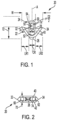
- FIG. 1 is a top view and Figure 2 is a front view of a distal end of one embodiment of a tissue anchor 20.
- the tissue anchor 20 includes a distal portion 22 and a proximal portion 24.
- the distal portion 22 provides a leading-most end 26 and the proximal portion 24 includes a shank 28 that terminates in a trailing-most end 30.
- a central longitudinal axis A is oriented from the leading-most end 26 to the trailing-most end 30.
- the leading-most end 26 is pointed and configured to penetrate tissue and the trailing-most end 30 is blunt.
- the tissue anchor 20 includes a front side 40 opposite of a backside 42.
- the front side 40 (top face) and the back side 40 (bottom face) can have different conformations.
- each of the front side 40 and the backside 42 is configured to be bi-laterally symmetric relative to the central longitudinal axis A.
- Bi-laterally symmetric means the left lateral side has the same conformation as the right lateral side, which is to say that the two lateral sides are mirror images of each other.
- the front side 40 and the backside 42 of the tissue anchor include a central region CR that is centered on the longitudinal axis A, a first lateral region LR1 extending from the central region CR to a first barb 32, and a second lateral region LR2 extending opposite from the first lateral region LR1 from the central region CR to a second barb 34.
- the leading-most end 26 is pointed in the form of a conical projection that is attached between the first lateral region LR1 and the second lateral region LR2, where the first lateral region LR1 and the second lateral region LR2 are arched in a parabola-shape and support the conical projection of the leading-most end 26.
- an opening 50 is formed entirely through the tissue anchor 20 from the front side 40 through the backside 42 in the central region CR.
- the opening 50 includes a first aperture 52 connected to a second aperture 54, with a diameter D 1 of the first aperture 52 sized to be larger than a diameter D to of the second aperture 54 by at least a factor of 2.
- Figure 1 illustrates one exemplary embodiment where a radius r of the second aperture 54 is equal to the diameter D2/2, although other ratios are possible.
- the opening 50 occupies more than 40% of a total area of the central region CR.
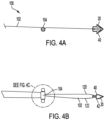
- Figure 2 is a front view of the tissue anchor 20.
- Fig. 2 shows the total frontal area of the anchor.
- a first slot 60 is formed longitudinally through an entirety of the first lateral region LR1 between the front side 40 and the backside 42.
- a second slot 62 is formed longitudinally through an entirety of the second lateral region LR2 between the front side 40 and the backside 42 of the tissue anchor 20.
- the first slot 60 is a first rectangular opening formed in the first lateral region LR1 between the central region CR and the first barb 32
- the second slot 62 is formed as a second rectangular opening formed in the second lateral region LR2 between the central region CR and the second barb 34.
- the first rectangular opening formed by the first slot 60 and the second rectangular opening formed by the second slot 62 combine to occupy about 20% of a total frontal area of the tissue anchor 20.
- a width W of the tissue anchor 20 measured from an end of the first barb 32 across the central region CR to an end of the second barb 34 is larger than a depth 70 of the tissue anchor measured from the front side 40 to the backside 42 by at least a factor of 3.
- the first aperture 52 is larger than the second aperture 54 and configured to allow the surgical staff to easily thread a length of suture into the opening 50.
- an entirety of the first aperture 52 is located between the leading-most end 26 and the end of the first barb 32.
- at least 50% of the first aperture 52 is located between the leading-most end 26 and the end of the first barb 32.
- a pointed end of the first barb 32 is located a longitudinal distance 72 from the leading-most end 26 of the tissue anchor 20, and an entirety of the first aperture 50 is formed within the longitudinal distance 72.
- the distal portion 22 of the tissue anchor 20 includes the leading-most end 26 and the first barb 32 and the second barb 34; and the proximal portion 24 of the tissue anchor 20 includes the shank 28 that is attached to the distal portion 22, and the second aperture 54 is formed in the shank 28 and an entirety of the first aperture 52 is formed in the distal portion 22.
- the proximal portion 24 provides the shank 28 and the distal portion 22 provides the tissue penetrating end 26, and the opening 50 is formed entirely through the front side 40 and the back side 42 and the central region CR of the tissue anchor 20, with the opening 50 including the first aperture 52 connected to the second aperture 54, with an entirety of the first aperture 52 formed within the distal portion 22 and the second aperture 54 formed in the shank 28.
- the first slot 60 is formed longitudinally through an entirety of the first lateral region LR1 between the front side 40 and the back side 42 of the tissue anchor 20, and the second slot 62 is formed longitudinally through an entirety of the second lateral region LR2 between the front side 40 and the back side 42 of the tissue anchor 20.
- the opening is separated from the first slot 60 and the second slot 62 by a wall 74.
- the shank 28 is connected to a tissue penetrating head defined by the distal portion 22, with the shank 28 providing the proximal most end 30 of the tissue anchor 20 and the tissue penetrating head providing the tissue penetrating leading end 26 of the tissue anchor 20.
- the tissue penetrating head extends in a longitudinal direction from the tissue penetrating leading end 26 to the shank 28.
- the opening 50 is formed in the tissue anchor 20 orthogonal to the longitudinal direction, with the opening 50 including the first aperture 52 connected to the second aperture 54, with an entirety of the first aperture 52 formed through a thickness of the tissue penetrating head and the second aperture 54 formed through a thickness of the shank 28.
- the tissue penetrating head includes the first lateral region LR1 extending from the first aperture 52 to the first barb 32 and the second lateral region LR2 extending opposite of the first lateral region LR1 from the first aperture 52 to a second barb 34.
- the first slot 60 is formed longitudinally through an entirety of the first lateral region LR1 of the tissue penetrating head and the second slot 62 is formed longitudinally through an entirety of the second lateral region LR2 of the tissue penetrating head.
- the first aperture 52 is separated from the first slot 60 and the second slot 62 by the wall 74.
- the opening 50 occupies from about 20% to 30% of the total planar area of the tissue anchor 20.
- the first and second slots occupy from about 6% to 10% of the frontal area of the tissue anchor 20.
- the tissue anchor 20 is suitably formed from a polymer that is not bioabsorbable, or a polymer that is bioabsorbable, or from a metal.
- the tissue anchor 20 is not bioabsorbable and is formed from one of polypropylene, polyethylene, or a polyether ether ketone.
- the tissue anchor 28 is resorbable after implantation into the tissue and is formed from, as examples, poly(L-lactic acid), poly(glycolic acid), poly(ortho ester), or poly(epsilon-caprolactone).
- the tissue anchor 20 is metal and is formed from, as examples, stainless steel or titanium.
- FIG 3 is a top view of one embodiment of the tissue anchor 20 coupled with a double-armed suture 80.
- the double-armed suture 80 includes a length of suture 82 having a first needle 84 connected to a first end of the suture 82 and a second needle 86 connected to a second end of the suture 82.
- the first needle 84 is fish-hook shaped, and the second needle 86 is not fish-hook shaped. Surgeons often have a strong preference for the type of suture and the size of the needles provided by the double-armed suture 80.
- the surgeon may desire to couple the double-armed suture 82 to an anchor for use in treating pelvic organ prolapse.
- the typical anchor includes a tissue penetrating portion at the front end and a shank at the proximal end, where the shank includes a small eyelet. Surgeons have expressed a level of frustration when passing one of the needles of the double-armed suture through the usual small eyelet of a typical anchor.
- the anchor 20 provides an opening 50 having the first aperture 52 sized to be significantly larger than the second aperture 54, such that the first aperture 52 provides a large target opening for passing one of the needles 84, 86 through the anchor 20.
- the diameter D1 of the first aperture 52 is in a range from 1-3 times larger than a diameter of the needle 84 or a diameter of the needle 86, and preferably in a range from 1-1.5 times larger than a diameter of the needle 84 or a diameter of the needle 86. Consequently, passage of the double-armed suture 80 through the opening 50 of the anchor 20 is substantially easier and more convenient than passing a double-armed suture through a conventional eyelet of a conventional anchor.
- the opening 50 extends most of the length of the tissue anchor 20. In one embodiment, the opening 50 extends in a range from 60% to 80% of the length of the anchor 20. The opening 50 extends substantially into the anchor head or distal region 22, which stands in stark contrast to the typical tissue anchor.
- the configuration of the relative diameters of the first aperture 52 compared to the second aperture 54 adapts the suture 82 to be transferred into the second aperture 54 when tension is applied to the suture.
- the opening 50 is a substantial portion of the length of the anchor 20, the anchor 20 is still stable when deployed due to the self-aligning nature of the second aperture 54 relative to the large target hole of the first aperture 52.
- the anchor 20 allows passage of the surgeon's choice of a prepackaged, double-armed suture.
- the first aperture 52 has a diameter D 1 of at least 1.0 mm. and preferably the diameter D1 of the first aperture 52 is at least 1.5 mm to accommodate a wide variety of needle sizes and shapes that are commercially available with USP Size 0 sutures.
- Anchors for securement of a suture in soft tissue have two features that influence its design: a barb feature that resists pull-out from tissue and an attachment feature (an eyelet) for retaining a suture.
- the distance or spacing from the wall of the anchor shank to the tip of the barb is related to pull-out strength, and the pull-out strength of the barb generally increases with the spacing.
- the anchor 20 allows passage of the surgeon's choice of pre-packaged, double-armed suture.
- the first aperture 52 is sized to accommodate the wide variety of needle sizes and shapes that are commercially available with USP Size 0 sutures. While it is possible to increase the size of the existing eyelet in a conventional anchor, this would leave a thin wall in the shank, resulting in a weakened part. Increasing the width of the shank is possible, but this approach results in enlargement of the head of the anchor to maintain the spacing to achieve the desired pull-out strength. Consequently, increasing the size of the existing eyelet in a conventional anchor would result in a larger anchor that is less desirable.
- the anchor 20 is a better solution since the eyelet (opening 50) is shaped to accommodate needles.
- the first aperture 52 has a relatively large diameter of, in one example, of 1.5 mm which is large enough for needles that are pre-attached to commercially available sutures.
- the first aperture 52 is distal to the barbs 32, 34 and is located within an area of the head of the anchor, so there is no increase in the size of the shaft 28 or the anchor 20. In fact, the overall size of the anchor 20 is significantly less than the currently available soft tissue anchors.
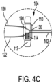
- FIG 4A is a side view
- Figure 4B as a top view
- Figure 4C is an expanded view of a tissue anchor assembly 100.
- the tissue anchor assembly 100 includes a suture 102 coupled between the tissue anchor 20 and a button 104.
- the tissue anchor 20 is provided for anchoring the tissue anchor assembly 100 into soft tissue
- the button 104 is provided to allow adjustment of the tension within the suture 102.
- Figure 4C is an expanded view of the button 104.
- the button 104 includes a sleeve 110 disposed over a central shaft 112, where one of the sleeve 110 or the shaft 112 is provided with locking splines 114.
- the suture 102 includes a first suture section 120 extending away from a front side 40 of the tissue anchor 20 and a second suture section 122 extending away from a backside 42 of the tissue anchor 20.
- the sleeve 110 includes a single proximal hole 130, a first distal hole 132, and a second distal hole 134, with the single proximal hole 130 located between opposing lateral edges of the sleeve 110 and placed laterally between the first distal hole 132 and the second distal hole 134.
- the locking splines 114 engage with the second suture section 122 to effectively connect the button 104 to the second suture section 122. Consequently, when tension is applied to the second suture section 122, the button 104 is engaged with the second suture section 122 and moves in the direction of the applied tension to loosen the tissue anchor assembly 100. In other words, tension applied to the second suture section 122 displaces the button 104 and increases a distance between the button 104 and the tissue anchor 20.
- tension applied to the first suture section 120 applies tension through the tissue anchor 20 and causes the button 104 to move in a direction towards a tissue anchor 20. Consequently, tension applied to the first suture section 120 reduces a distance between the button 104 and the tissue anchor 22 effectively "tighten” the tissue anchor assembly 100.
- the tissue anchor assembly includes the soft tissue anchor 20 and the button 104 which operates as an adjustable anchor provided to adjust tension in the suture 102.
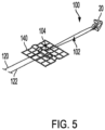
- Figure 5 is a perspective view of the tissue anchor assembly 100 coupled to a support 140.
- the button 104 has a relatively large aspect ratio where a length of the button is larger than a diameter of the button. The large aspect ratio of the button 104 allows one end of the button to be pushed through the support 140 to capture the button on a bottom side of the support while the suture 102 in the tissue anchor 20 remains on a top side of the support 140.
- the surgeon will place the soft tissue anchor 20 into soft tissue such as the sacrospinous ligament and then subsequently couple the button 104 to a support material 140.
- Tension applied to the first suture section 120 operates to tighten the tissue anchor assembly 100 and draw the support 140 closer to the tissue anchor 20.
- tension applied to the second suture section 122 will loosen the tissue anchor assembly 100 and move the support 140 away from the soft tissue anchor 20.
- the support 140 can be a synthetic support, a native tissue support, a human tissue support harvested from a cadaver, or a tissue support harvested from a transgenic animal such as a porcine animal.
- the support 140 is a Restorelle ® synthetic mesh material available from Coloplast Corp., Minneapolis Minnesota.
- a tissue anchor system 200 is provided that includes the tissue anchor 20, a length of suture 202, and a tool 204 to place the tissue anchor 20 into soft tissue.
- One embodiment of the tissue anchor system 200 is best illustrated in Figure 13A , which is described below.
- Figure 6 is a top view
- Figure 7 is a side view
- Figure 8 is a perspective view of one embodiment of the tool 204.
- the tool 204 includes a handle 210 on a proximal end, a clip 212 on a distal end, a shaft 214 coupled between the handle 210 and the clip 212, and a sleeve 216 that is provided to protect the clip 212 when it is engaged with the anchor 20.
- FIG 9 is exploded view of a portion of the tissue anchor system 200.
- the tissue anchor system 200 includes the tissue anchor 20, a length of suture 202 coupled to the tissue anchor 20, and the tool 204 provided with the clip 212 that is configured to be attached to the anchor 20, deliver the anchor 20, and be removed from the anchor 20.
- the tool 204 is provided with the clip 212 that is adapted to engage with the anchor 20.
- the clip 212 includes a first clip arm 220 and a second clip arm 222.
- the first clip arm 220 is insertable through the slot 60 ( Figure 2 ) and the second clip arm 222 is insertable into the slot 62. In this way, the clip arms 220, 222 of the clip 212 slide into and engage the entire longitudinal extent of the anchor 20.
- the sleeve 216 is retractable and slides relative to the shaft 214 of the tool 204.
- the sleeve 216 is assembled to the shaft 214 by sliding the proximal end 230 of the sleeve 216 over the clip 212 and inserting a pin 232 into a gate 234 of the sleeve 216.
- the pin 232 is permanently connected to the shaft 214 to ensure that both the pin 232 and the sleeve 216 remain coupled to the tool 204 throughout its life cycle.
- the pin 232 is provided with a ramp that inclines from the distal end to the proximal end of the pin 232.
- the ramped pin 232 allow the sleeve 216 to slide up the pin 232 when the sleeve 216 is pushed in a proximal direction to attach the sleeve 216 to the shaft 214.
- the ramped pin 232 prevents the sleeve 216 from sliding off the shaft 214 in the distal direction.
- the sleeve 216 is retractable relative to the clip 212 by a retraction distance that is equal to a length of the gate 234 formed in the top surface of the sleeve 216.
- the pin 232 and the gate 234 combine to provide the sleeve 216 with a stroke in a range of about 4-12 mm, preferably the stroke of the sleeve 216 along the shaft 214 is in a range of about 6-9 mm.
- the shaft 214 includes a flat 236 that engages with and prevents rotation of the sleeve 216 relative to the shaft 214.
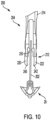
- Figure 10 is a top view of the clip 212 positioned for engagement with the anchor 20
- Figure 11 is a top view of the clip 212 coupled to the anchor 20.
- a back-table nurse or the surgeon will load the anchor 20 into the tool 204 by maintaining the suture 220 in a comfortable position along the shaft 214 of the tool.
- the first clip arm to 20 and the second clip arm 222 are inserted into the slots 60, 62, respectively, of the anchor 20.
- Each of the clip arms 220, 222 extend through an entire longitudinal length of the anchor 20.
- the first clip arm 220 includes a first pincher 240 and the second clip arm 222 includes a second pincher 242.
- the pinchers 240, 242 are flexible and move laterally to allow engagement of the pinchers with the anchor 20.
- Figure 11 illustrates the anchor 20 engaged with the clip 212 where the first pincher 240 and the second pincher 242 pinch inwardly to capture the anchor 20 within the clip 212.
- the shank 28 of the anchor 20 bottoms out and is in contact with a base 250 located between the first clip arm 220 and the second clip arm 222. This allows the tool 204 to push the anchor 20 into soft tissue.
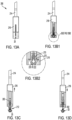
- Figure 12 is a perspective view of a cartridge 260 maintaining one or more anchors 20 in position for loading into the tool 204.
- the anchors 20 are small.
- the anchors 20 can be manually loaded into the tool 204.
- the cartridge 260 provides a convenient increased grasping area that allows easy handling of the small anchors 20.
- the cartridge 260 holds a plurality of the anchors 20 within individual garages 262.
- the sleeve 216 is retracted in a proximal direction to expose the clip 212.
- the clip 212 is inserted into the garage 262 and the first clip arm 220 is inserted into the first slot 60 and the second clip arm 222 is inserted into the second slot 62 of the anchor 20.
- the pinchers 240, 242 close upon the anchor 20.
- the sleeve 216 is moved in a distal direction to close the clip arms 220, 222 into engagement with the anchor 20.
- the sleeve 216 is disposed over both the clip arms 220, 222 and the anchor 22 protectively prevent snagging the anchor against tissue during the placement procedure of the anchor inside of the body.
- Figure 13A - Figure 13D illustrate delivery motions of the anchor from the tissue anchor system 200.
- Figure 13A is a top view and Figure 13B is a sectional view that illustrate the anchor 20 engaged by the clip 212 and protectively covered by the sleeve 216.
- the sleeve 216 When the sleeve 216 is in the distalmost position protectively covering the clip 212, the sleeve 216 operates to pinch the clip arms 220, 222 inward to capture the anchor 20.
- each of the pinch arms 220, 222 includes an indent 270 and the sleeve includes a detent 272 that pushes against the indent 270 to hold the clip arms 220, 222 against the anchor 20.
- Figure 13C illustrates the sleeve 216 retracted in a proximal direction and out of engagement with the clip arms 220, 222.
- the clip arms 220, 222 engaged to hold the anchor 20, but also allow the anchor 20 to slide relative to the clip 212.
- Figure 13C illustrates embodiment where the shaft 214 has been pushed in a distal direction to engage the anchor 20 with soft tissue.
- Figure 13D illustrates that the anchor 20 has been delivered out from the clip 212 and the sleeve 216 has been moved in the distal direction over the clip 212. In this configuration, the anchor 20 has been delivered and the tool 204 is in position for removal from the patient.
- the slideable sheath 216 encloses the clip 212 and the anchor 20 to ensure that these components do not drag or catch soft tissue as the anchor 20 is carried through a surgical dissection to the targeted anchor site.
- the clip 212 slides within the sheath 216, and the clip arms 220, 222 flex outward when they pass in the distal direction beyond the distal end of the sheath 216. This feature prevents unintentional release of the anchor 20 while the anchor 20 is retracted within the sheath 216.
- the sheath 216 has the internal detent bumps 270 that mate with indentations 272 on the clip 212, which prevents the sliding motion between the clip 212 and the sheath 216 until enough force is applied to the distal end of the sheath 216.
- the anchor 20 will only be exposed when the distal end of the sheath 216 is pressed with sufficient force against the target soft tissue, for example, through application of a thrust force on the clip 212.
- a biasing spring is employed in place of the detent 270 to achieve the same resistance to sliding movement.
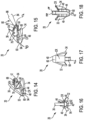
- FIG 14 is a perspective view of one embodiment of an anchor 20.
- the tissue anchor 20 includes a distal end 40 opposite of a proximal end 42.
- the distal end 40 of the anchor 20 is blunt, although the anchor tapers to the distal end to allow for tissue penetration.
- the anchor 20 includes a central region CR between the distal end 40 and the proximal end 42.
- the anchor 20 includes a first barb 32, a second barb 34, and a third barb 36 extending from the central region CR.
- the first barb 32 and the second barb 32 extend laterally from the central region CR.
- the third barb 36 extends from the central region CR substantially perpendicular to the first barb 32 and/or the second barb 34.
- the central region CR includes a top surface 44, and side surfaces 46, 48 with the first barb 32 and the second barb 34 extending in opposite directions from opposing side surfaces 46, 48 of the central region CR.
- the opposing side surfaces 46, 48 are laterally opposing surfaces, and the slot 60 is longitudinal relative to the laterally side surfaces 46, 48.
- the third barb 36 extends from the top surface 44 of the central region CR. In certain instances, the third barb 36 has a width less than a width of the central region CR.
- the anchor 20 also includes a slot 60 arranged through the central region CR from the distal end 40 to the proximal end 42 as is shown in further detail in Figures 15-16 .
- the slot 60 is configured to interface with a delivery mechanism as shown in Figures 19-20 .
- the slot 60 may be vertically offset from an aperture 54.
- the aperture 54 allows passage of a suture (e.g., a surgeon's choice of a prepackaged, double-armed suture) as shown in FIG. 15 .
- the anchor 20 includes a proximal portion 64 with the aperture 54 extending laterally through the proximal portion 64.
- the aperture 54 extends laterally through the anchor 20 and the slot 60 extends axially through the anchor 20.
- Figure 15 is a side view of the anchor 20 and Figure 16 is a front view of the anchor 20.
- the tissue anchor 20 may be coupled with a double-armed suture 80.
- the double-armed suture 80 includes a length of suture 82 having a first needle 84 connected to a first end of the suture 82 and a second needle 86 connected to a second end of the suture 82.
- the aperture 54 includes a first portion 68 and a second portion 76.
- the first portion 68 and the second portion 76 of the aperture 54 may be of different sizes.
- the first portion 68 of the aperture 54 may be smaller than the second portion 76 of the aperture 54.
- the aperture 54 increases in size toward the distal end 40 of the anchor 20.
- This arrangement of the aperture 54 facilitates arrangement of the suture 80 through the anchor 20.
- the anchor 20 provides a large target opening for passing one of the needles 84, 86 through the anchor 20. Consequently, passage of the double-armed suture 80 through the aperture 54 of the anchor 20 may be easier and more convenient than passing a double-armed suture through a conventional eyelet of a conventional anchor.
- the proximal portion 64 of the central region CR of the anchor 20 extends distal to a proximal end 88 of the slot 60.
- at least a portion of the aperture 54 is arranged proximal to the slot 60.
- the third barb 36 may extend from the opposing end 94 of the slot 60.
- the slot 60 is configured to interface with a delivery mechanism.
- the proximal end 88 of the slot 60 being longitudinally offset from the aperture 54 facilitates interaction with the delivery tool while allowing the surgeon to thread the suture 80 through the aperture 54.
- the aperture 54 by way of the proximal portion 64 of the anchor 20, extends longitudinally beyond the third barb 36.
- the first barb 32 and the second barb 34 extend laterally from the central region CR.
- the first barb 32 and the second barb 34 may extend at a downward angle relative to the opposing side surfaces 46, 48 of the central region CR. In certain instances, the opposing side surfaces 46, 48 do not extend vertically below the remaining portions of the central region CR
- the slot 60 includes an upper surface 90 and a lower surface 92.
- the upper surface 90 of the slot 60 extends across the central region CR.
- the upper surface 90 of the slot 60 is substantially flat.
- the lower surface 92 of the slot 60 may be curved. In certain instances, the lower surface 92 of the slot 60 is a semi-circle.
- the non-circular shape of the slot 60 facilitates interaction with a delivery tool.
- the proximal portion 64 of the anchor 20 may have a width greater than a width of the third barb 36.
- Figure 19 is a perspective view of a tool 204 for placing an anchor in a first configuration with the anchor 20 coupled to the tool 204 and Figure 20 is a perspective view of the tool 204 in a second configuration with the anchor 20 uncoupled from the tool 204.
- the tool 204 includes a shaft 218 that is configured to extend through the slot 60 in the anchor 20. Slot 60 and shaft 218 may be sized such that there is an interference fit that prevents anchor 20 from easily detaching from tool 204. In certain instances, and as shown in Figure 19 , the shaft 218 extends beyond the distal end 94 of the slot 60.
- the anchor 20 may rest within a portion of the tool 204.
- the tool 204 may include a cannula (or a tube) 214 supporting the shaft 218. As discussed in detail with reference to Figure 21 , the tool 204 may include a mechanism to retract the shaft 218 to cause the cannula 214 to force or push the anchor 20 from the shaft 218.
- the proximal portion 64 of the anchor 20 may nest within the cannula 214.
- the cannula 214 may include a groove 228 into which the proximal portion 64 of the anchor 20 may nest within when the anchor 20 is coupled to the tool 204. Actuation of the shaft 218 forces the proximal portion 64 of the anchor 20 from the groove 228 by pushing the anchor 20 from an end 238 of the tool 204.
- the tool 204 facilitates placement of the anchor 20 into soft tissue such as the sacrospinous ligament or the arcus tendineus ligament.
- the anchor 20 may include a suture 82.
- two anchors 20 may be embedded in the left and right sacrospinous ligament and two anchors 20 within the left and right arcus tendineus ligament or nearby muscle.
- the support material 140 may be guided through an incision (e.g ., a vaginal incision) and a physician can couple the support material 140 to each one of the sutures 82 that are arranged through the anchors 20.
- Sutures 82 extending from the anchors 20 may serve as guides for a support material 140 (discussed in detail above).
- the support material 140 may be slid along the sutures 82.
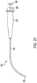
- Figure 21 is a side view of a tool 204 for placing an anchor.
- the tool 204 includes a handle 210 on a proximal end, a cannula 214 coupled to the handle 210, a cannula (shown in Figures 19 and 20 ), and a plunger button 246.
- the plunger button 246 is used to actuate the delivery mechanism, causing the shaft 218 and anchor 20 at the distal end 238 to extend into the target tissue.
- the plunger button 246 may be spring-loaded to minimize unintended actuation.
- the plunger button 246 also includes a locking mechanism that engages when the plunger button 246 is actuated beyond a certain point. This provides feedback such that actuation has been fully completed and keeps the shaft 218 extended for subsequent reloading with a subsequent anchor 20 if desired. This locking mechanism will be disengaged by pushing an option button 256, twisting the plunger button 246, or pulling back on the plunger button 246.
Landscapes
- Health & Medical Sciences (AREA)
- Life Sciences & Earth Sciences (AREA)
- Surgery (AREA)
- Heart & Thoracic Surgery (AREA)
- Engineering & Computer Science (AREA)
- Biomedical Technology (AREA)
- Nuclear Medicine, Radiotherapy & Molecular Imaging (AREA)
- Medical Informatics (AREA)
- Molecular Biology (AREA)
- Animal Behavior & Ethology (AREA)
- General Health & Medical Sciences (AREA)
- Public Health (AREA)
- Veterinary Medicine (AREA)
- Rheumatology (AREA)
- Surgical Instruments (AREA)
Applications Claiming Priority (2)
| Application Number | Priority Date | Filing Date | Title |
|---|---|---|---|
| US201862640577P | 2018-03-09 | 2018-03-09 | |
| EP19161488.2A EP3536249B1 (de) | 2018-03-09 | 2019-03-08 | Gewebeanker, gewebeankeranordnung und gewebeankersystem |
Related Parent Applications (1)
| Application Number | Title | Priority Date | Filing Date |
|---|---|---|---|
| EP19161488.2A Division EP3536249B1 (de) | 2018-03-09 | 2019-03-08 | Gewebeanker, gewebeankeranordnung und gewebeankersystem |
Publications (2)
| Publication Number | Publication Date |
|---|---|
| EP4406491A2 true EP4406491A2 (de) | 2024-07-31 |
| EP4406491A3 EP4406491A3 (de) | 2024-10-30 |
Family
ID=65729151
Family Applications (2)
| Application Number | Title | Priority Date | Filing Date |
|---|---|---|---|
| EP19161488.2A Active EP3536249B1 (de) | 2018-03-09 | 2019-03-08 | Gewebeanker, gewebeankeranordnung und gewebeankersystem |
| EP24176607.0A Pending EP4406491A3 (de) | 2018-03-09 | 2019-03-08 | Gewebeanker, gewebeankeranordnung und gewebeankersystem |
Family Applications Before (1)
| Application Number | Title | Priority Date | Filing Date |
|---|---|---|---|
| EP19161488.2A Active EP3536249B1 (de) | 2018-03-09 | 2019-03-08 | Gewebeanker, gewebeankeranordnung und gewebeankersystem |
Country Status (3)
| Country | Link |
|---|---|
| US (2) | US11045184B2 (de) |
| EP (2) | EP3536249B1 (de) |
| ES (1) | ES2985400T3 (de) |
Families Citing this family (4)
| Publication number | Priority date | Publication date | Assignee | Title |
|---|---|---|---|---|
| US11406525B2 (en) | 2017-11-09 | 2022-08-09 | 11 Health And Technologies Limited | Ostomy monitoring system and method |
| USD893514S1 (en) | 2018-11-08 | 2020-08-18 | 11 Health And Technologies Limited | Display screen or portion thereof with graphical user interface |
| FR3095586B1 (fr) * | 2019-05-05 | 2023-09-29 | Missana Marie Christine | Implant mammaire muni d’une attache de fixation |
| AU2021361238A1 (en) | 2020-10-15 | 2023-05-25 | Convatec Technologies Inc. | Ostomy systems and methods |
Family Cites Families (26)
| Publication number | Priority date | Publication date | Assignee | Title |
|---|---|---|---|---|
| US4506417A (en) * | 1983-05-06 | 1985-03-26 | Nifco Inc. | Fastener for string |
| US4991593A (en) * | 1989-06-13 | 1991-02-12 | Minnesota Scientific, Inc. | Flexible bag for storing body organs |
| US6015427A (en) * | 1997-07-07 | 2000-01-18 | Eclipse Surgical Technologies, Inc. | Heart stabilizer with controllable stay suture and cutting element |
| US5894639A (en) * | 1998-03-19 | 1999-04-20 | Robert O. Boden | Cord lock apparatus |
| AU737877B2 (en) | 1998-05-21 | 2001-09-06 | Christopher J. Walshe | A tissue anchor system |
| US6202443B1 (en) * | 1999-02-24 | 2001-03-20 | Jacquelin Annette Grosser-Samuels | Adjustable jewelry |
| JP4305693B2 (ja) * | 1999-04-26 | 2009-07-29 | 株式会社ニフコ | 紐留め用バックル |
| US7887551B2 (en) * | 1999-12-02 | 2011-02-15 | Smith & Nephew, Inc. | Soft tissue attachment and repair |
| US20050090827A1 (en) * | 2003-10-28 | 2005-04-28 | Tewodros Gedebou | Comprehensive tissue attachment system |
| US20090248071A1 (en) * | 2008-03-07 | 2009-10-01 | Alure Medical , Inc. | Minimally invasive tissue support |
| US8419769B2 (en) | 2007-11-07 | 2013-04-16 | Raymond Thal | Adjustable loop knotless anchor |
| US9907638B2 (en) | 2008-11-03 | 2018-03-06 | Ian L. Goldman | Atraumatic medical device anchoring and delivery system with enhanced anchoring |
| US8449573B2 (en) | 2008-12-05 | 2013-05-28 | Boston Scientific Scimed, Inc. | Insertion device and method for delivery of a mesh carrier |
| WO2010102131A1 (en) * | 2009-03-04 | 2010-09-10 | The United States Of America As Represented By The Secretary, Department Of Health And Human Services | Tensioning device and methods for use |
| US8460379B2 (en) * | 2009-03-31 | 2013-06-11 | Arthrex, Inc. | Adjustable suture button construct and methods of tissue reconstruction |
| US9328799B2 (en) * | 2010-07-08 | 2016-05-03 | Bed Band Store, LLC | Multi-purpose adjustable retaining device |
| US9414903B2 (en) | 2011-07-22 | 2016-08-16 | Astora Women's Health, Llc | Pelvic implant system and method |
| JP5956586B2 (ja) * | 2011-10-03 | 2016-07-27 | カイエン メディカル インコーポレイテッド | 縫合糸固定具およびその使用方法 |
| WO2013114347A1 (en) | 2012-02-05 | 2013-08-08 | Implament Pty Limited | Suture anchor with cleat formation to secure suture thread |
| US9439747B2 (en) | 2012-02-22 | 2016-09-13 | Boston Scientific Scimed, Inc. | Adjustable medical assembly for implant tension adjustment |
| FR2991159B1 (fr) * | 2012-06-05 | 2015-07-17 | In2Bones | Ancre medicale rotative et kit medical comprenant ladite ancre |
| WO2014146023A2 (en) | 2013-03-15 | 2014-09-18 | Ams Research Corporation | Surgical implant system and method |
| US20150359530A1 (en) * | 2014-06-16 | 2015-12-17 | Dauntless Innovations, LLC | Vector fixation device |
| US9693856B2 (en) | 2015-04-22 | 2017-07-04 | DePuy Synthes Products, LLC | Biceps repair device |
| WO2017011459A1 (en) | 2015-07-12 | 2017-01-19 | Astora Women's Health, Llc | Adjustable surgigal implant system and method |
| US10722343B2 (en) * | 2017-02-22 | 2020-07-28 | Stryker Corporation | Fixation member with separate eyelet and methods of use thereof |
-
2019
- 2019-03-08 ES ES19161488T patent/ES2985400T3/es active Active
- 2019-03-08 US US16/296,293 patent/US11045184B2/en active Active
- 2019-03-08 EP EP19161488.2A patent/EP3536249B1/de active Active
- 2019-03-08 EP EP24176607.0A patent/EP4406491A3/de active Pending
-
2021
- 2021-05-26 US US17/330,520 patent/US11849935B2/en active Active
Also Published As
| Publication number | Publication date |
|---|---|
| US11849935B2 (en) | 2023-12-26 |
| ES2985400T3 (es) | 2024-11-05 |
| EP3536249A1 (de) | 2019-09-11 |
| EP3536249C0 (de) | 2024-05-22 |
| EP4406491A3 (de) | 2024-10-30 |
| US11045184B2 (en) | 2021-06-29 |
| EP3536249B1 (de) | 2024-05-22 |
| US20190274672A1 (en) | 2019-09-12 |
| US20210275164A1 (en) | 2021-09-09 |
Similar Documents
| Publication | Publication Date | Title |
|---|---|---|
| US11849935B2 (en) | Tissue anchor assembly with an adjustment button | |
| US11446129B2 (en) | Surgical articles and methods | |
| US8876843B2 (en) | Apparatus for placing medical implants | |
| US10456230B2 (en) | Method of fixing surgical suture to tissue | |
| EP1455653B1 (de) | Chirurgisches befestigungselement mit anker und clip | |
| US9549810B2 (en) | Graft introducer | |
| US20150148820A1 (en) | Apparatus for delivering and anchoring implantable medical devices | |
| US20090216250A1 (en) | Device and Method for Carrying Material Through Tissue | |
| US9445881B2 (en) | Surgical articles and methods | |
| US12484892B2 (en) | Suture-based assembly for tissue repair, and associated devices and methods |
Legal Events
| Date | Code | Title | Description |
|---|---|---|---|
| PUAI | Public reference made under article 153(3) epc to a published international application that has entered the european phase |
Free format text: ORIGINAL CODE: 0009012 |
|
| STAA | Information on the status of an ep patent application or granted ep patent |
Free format text: STATUS: THE APPLICATION HAS BEEN PUBLISHED |
|
| AC | Divisional application: reference to earlier application |
Ref document number: 3536249 Country of ref document: EP Kind code of ref document: P |
|
| AK | Designated contracting states |
Kind code of ref document: A2 Designated state(s): AL AT BE BG CH CY CZ DE DK EE ES FI FR GB GR HR HU IE IS IT LI LT LU LV MC MK MT NL NO PL PT RO RS SE SI SK SM TR |
|
| PUAL | Search report despatched |
Free format text: ORIGINAL CODE: 0009013 |
|
| AK | Designated contracting states |
Kind code of ref document: A3 Designated state(s): AL AT BE BG CH CY CZ DE DK EE ES FI FR GB GR HR HU IE IS IT LI LT LU LV MC MK MT NL NO PL PT RO RS SE SI SK SM TR |
|
| RIC1 | Information provided on ipc code assigned before grant |
Ipc: A61B 17/04 20060101AFI20240920BHEP |
|
| STAA | Information on the status of an ep patent application or granted ep patent |
Free format text: STATUS: REQUEST FOR EXAMINATION WAS MADE |
|
| 17P | Request for examination filed |
Effective date: 20250430 |