EP4406460A2 - Brüheinheit - Google Patents
Brüheinheit Download PDFInfo
- Publication number
- EP4406460A2 EP4406460A2 EP24180106.7A EP24180106A EP4406460A2 EP 4406460 A2 EP4406460 A2 EP 4406460A2 EP 24180106 A EP24180106 A EP 24180106A EP 4406460 A2 EP4406460 A2 EP 4406460A2
- Authority
- EP
- European Patent Office
- Prior art keywords
- assembly part
- brewing
- unit according
- powdered product
- plunger
- Prior art date
- Legal status (The legal status is an assumption and is not a legal conclusion. Google has not performed a legal analysis and makes no representation as to the accuracy of the status listed.)
- Pending
Links
Images













Classifications
-
- A—HUMAN NECESSITIES
- A47—FURNITURE; DOMESTIC ARTICLES OR APPLIANCES; COFFEE MILLS; SPICE MILLS; SUCTION CLEANERS IN GENERAL
- A47J—KITCHEN EQUIPMENT; COFFEE MILLS; SPICE MILLS; APPARATUS FOR MAKING BEVERAGES
- A47J31/00—Apparatus for making beverages
- A47J31/44—Parts or details or accessories of beverage-making apparatus
- A47J31/4403—Constructional details
- A47J31/446—Filter holding means; Attachment of filters to beverage-making apparatus
- A47J31/4467—Filter holding means; Attachment of filters to beverage-making apparatus by means of linear guides, e.g. drawer-type engagement
-
- A—HUMAN NECESSITIES
- A47—FURNITURE; DOMESTIC ARTICLES OR APPLIANCES; COFFEE MILLS; SPICE MILLS; SUCTION CLEANERS IN GENERAL
- A47J—KITCHEN EQUIPMENT; COFFEE MILLS; SPICE MILLS; APPARATUS FOR MAKING BEVERAGES
- A47J31/00—Apparatus for making beverages
- A47J31/44—Parts or details or accessories of beverage-making apparatus
- A47J31/4492—Means to read code provided on ingredient pod or cartridge
-
- A—HUMAN NECESSITIES
- A47—FURNITURE; DOMESTIC ARTICLES OR APPLIANCES; COFFEE MILLS; SPICE MILLS; SUCTION CLEANERS IN GENERAL
- A47J—KITCHEN EQUIPMENT; COFFEE MILLS; SPICE MILLS; APPARATUS FOR MAKING BEVERAGES
- A47J31/00—Apparatus for making beverages
- A47J31/44—Parts or details or accessories of beverage-making apparatus
- A47J31/46—Dispensing spouts, pumps, drain valves or like liquid transporting devices
- A47J31/461—Valves, e.g. drain valves
-
- A—HUMAN NECESSITIES
- A47—FURNITURE; DOMESTIC ARTICLES OR APPLIANCES; COFFEE MILLS; SPICE MILLS; SUCTION CLEANERS IN GENERAL
- A47J—KITCHEN EQUIPMENT; COFFEE MILLS; SPICE MILLS; APPARATUS FOR MAKING BEVERAGES
- A47J31/00—Apparatus for making beverages
- A47J31/44—Parts or details or accessories of beverage-making apparatus
- A47J31/52—Alarm-clock-controlled mechanisms for coffee- or tea-making apparatus ; Timers for coffee- or tea-making apparatus; Electronic control devices for coffee- or tea-making apparatus
Definitions
- the present invention relates to a brewing unit for a machine for preparing beverages through the use of a powdered product containing one or more ingredients, in particular coffee.
- the object of the present invention is to provide an improved brewing unit.
- the invention further relates to a method for preparing a beverage as defined in the appended independent claim 11.
- the invention relates to a brewing unit for the preparation of beverages from a powdered product containing at least one ingredient in form of a compacted tablet, comprising
- the brewing head and filtering element act as protective elements, preventing any residue which may accumulate in the brewing chamber from entering the hydraulic lines of the first and second assembly parts, respectively.
- a brewing unit for a machine for preparing beverages, in particular coffee, from a compacted tablet containing one or more ingredients, in particular coffee powder is collectively denoted as 10.
- the term "powdered product” covers the powdered product compacted into tablet form.
- the brewing unit 10 basically comprises a dispensing assembly including a first assembly part 12 made as a drawer and a second movable assembly part 14 and a support structure 20 that supports the first assembly part 12 and the second assembly part 14 and defines an internal cavity 16.
- An insertion opening 16a formed on a front wall of the support structure 20, provides access to the cavity 16.
- the first assembly part 12 is insertable into or extractable from a lower part of the cavity 16 and has a receptacle 13 adapted to receive a powdered product P as a compacted tablet.
- Fig. 2 , 6 , and 11 show a condition wherein the first assembly part 12 is completely extracted from the cavity 16. In this condition the first assembly part 12 is released from the support structure 20 and may be used for inserting the powdered product P into the receptacle 13, or for cleaning operations.
- Fig. 8-9 and 14-15 show a condition in which the first assembly part 12 is in an insertion end position.
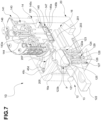
- Fig. 3 , 7 , and 12-13 represent intermediate positions of the first assembly part 12.
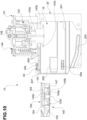
- the second assembly part 14 is mounted to slide vertically within an upper part of the cavity 16, between a raised end position depicted in Fig. 5-8 and 10-14 and a lowered end position depicted in Fig. 9 and 15 . In its raised end position, the second assembly part 14 allows insertion or extraction of the first assembly part 12 into or from the internal cavity 16. In the lowered end position, the second assembly part 14 and the first assembly part 12 are coupled to each other to jointly define a brewing chamber.
- the receptacle 13 is adapted to form, together with the second assembly part 14, the brewing chamber.
- the first assembly part 12 is made as a drawer and comprises a main portion 121 made as a sleeve and a handle 122 connected to the main portion 121, which allows manipulation of the first assembly part 12.
- the receptacle 13 In the upper end of the main portion 121 is obtained the receptacle 13. Lateral sides of the main portion 121 of the first assembly part 12 are adapted to be coupled to respective main guides 201 formed on opposite lateral sides of the support structure 20, to allow the first assembly part 12 to slide relative to the support structure 20 and thus the insertion/extraction of the first assembly part 12.
- a filtering element 123 is mounted to translate vertically through which a central dispensing duct 124 is formed for dispensing the beverage.
- the filtering element 123 is slidable between a raised end position, depicted in Fig. 6-7 and 11-12 , and a lowered end position, depicted in Fig. 9 and 15 , in which the filtering element abuts against a shoulder 121a formed on the main portion 121 of the first assembly part 12.
- the filtering element comprises a main body 123a and a filtering screen 123b attached to the main body 123a.
- the filtering screen 123b may be heat-locked, for example fixed to spindle pins 123c extending from the main body 123a.
- this arrangement provides planar surfaces which reduce possible dust accumulation.
- the filtering element 123 more specifically the filtering screen 123b, defines a bottom surface of the receptacle 13, and therefore also defines a bottom surface of the brewing chamber when the first assembly part 12 and the second assembly part 14 are coupled to each other.
- the filtering element 123 therefore provides a support surface for the powdered product P positioned in the receptacle 13.
- a peripheral gasket 125 Arranged around the filtering element 123 is a peripheral gasket 125 configured to exert a seal against a radially inner surface of the receptacle 13.
- the peripheral gasket 125 allows the radially inner surface of the receptacle 13 to be scraped clean of any residual powder when the filtering element 123 slides within the receptacle 13 from a lowered position to a raised end position.
- the filtering element 123 is associated with a driving element 126, which is mounted to translate vertically within the first assembly part 12, more specifically within the main portion 121 of the first assembly part 12.
- the filtering element 123 is connected to the driving element 126 through elastic means 127, in particular a coil spring.
- elastic means 127 in particular a coil spring.
- a central dispensing duct 128 is formed through the driving element 126, which is fluidically connected to the central dispensing duct 124 of the filtering element 123 through a pre-brewing valve 129 interposed between the filtering element 123 and the driving element 126.
- the pre-brewing valve 129 comprises a valve member cooperating with a seat formed on the dispensing duct 124 of the filtering element 123 with which elastic means, in particular a spring, are associated. The object of this valve will be described hereinafter.
- respective pins integral with the driving element 126 On opposite sides of a lower end of the driving element 126 are arranged respective pins integral with the driving element 126, one of which is visible in Fig. 2 and denoted as 131.
- the pins 131 are adapted to engage respective secondary guides 203 formed on opposite lateral walls of the support structure.
- the secondary guides 203 are inclined downward, unlike the primary guides 201 that guide the sliding of the first assembly part 12 into the cavity 16 of the support structure 20, such guides being oriented horizontally.
- Such an arrangement ensures that during the sliding of the first assembly part 12 within the cavity 16, the driving element 126 is induced to translate vertically with respect to the first assembly part 12 by the coupling between the pins 131 and the secondary guides 203, driving with it the filtering element 123 and the powdered product P possibly positioned in the receptacle 13.
- a hydraulic cylinder 141 Associated with the second assembly part 14 is a hydraulic cylinder 141, in which a vertically sliding plunger 143 is mounted.
- the plunger 143 is part of the second assembly part 14.
- An inlet 141a is shown in Fig. 1-4 , through which the hydraulic cylinder 141 may be supplied with a liquid, in particular water, through ducts not shown, to control the forward motion of the plunger 143 from its retracted position shown in Fig. 5-8 and 10-14 , at the raised end position of the second assembly part 14.
- the forward motion of the plunger 143 is counteracted by elastic means 144 which comprise in particular a coil spring and are interposed between the plunger 143 and the hydraulic cylinder 141.
- elastic means 144 are therefore arranged to bias the plunger 143 toward the retracted position thereof.
- a central duct 143a is formed through the plunger 143, which is connected to a water supply duct 146 obtained through the hydraulic cylinder 141.
- a flange 143b is obtained on a lower end of the plunger 143.
- a brewing head 145 integral with the plunger 143 is arranged on the lower end of the plunger 143 and is a part of the second assembly part 14. Ducts for injecting water into the brewing chamber are obtained through the brewing head 125, which are fluidically connected to the central duct 143a of the plunger 143.
- the brewing head 145 comprises a main body 145a and an interface element 145b fastened to the main body 145a.
- the interface element 145b may be heat-locked, for example fixed to spindle pins extending from the main body 145a.
- this arrangement provides planar surfaces which reduce possible dust accumulation.
- the brewing head 145, or more specifically the interface element 145b, defines a top surface of the brewing chamber.
- the interface element 145b is intended to come in contact with the powdered product P.
- the interface element 145b is constructed as a filter screen and will be denoted as an inlet filter hereinafter.
- the interface element could be constructed as an element provided with tips for piercing the capsule casing.
- a peripheral gasket 147 Arranged around the brewing head 145 is a peripheral gasket 147 configured to come in contact with a radially internal surface of the receptacle 13 in the lowered position of the second assembly part 14.
- the peripheral gasket 147 allows the radially internal surface of the receptacle 13 to be scraped clean of any residual powder when the brewing head 145 slides within the receptacle 13.
- the brewing head 145 is integral with an intermediate member 150 removably mounted on the lower end of the plunger 143.
- Fig. 1 , 5 and 10 show precisely the intermediate member 150 in a condition wherein the intermediate member 150 is detached from the lower end of the plunger 143. In this condition, the brewing head 145 may be cleaned. In the other figures, however, the intermediate member 150 is in a condition of being mounted on the lower end of the plunger 143.
- the intermediate member 150 is constructed as a drawer and comprises a main frame portion 151 carrying the brewing head 145 and a handle 152 connected to the main frame portion 151, which allows for the intermediate member 150 to be manipulated.
- Lateral sides of the main portion 151 of the intermediate member 150 are adapted to be coupled to respective auxiliary guides 205 formed on opposite lateral walls of the support structure 20 to allow the intermediate member 150 to slide relative to the support structure 20 and thus for the intermediate member 150 to be inserted/extracted.
- the intermediate member 150 is therefore selectively removable from or mountable on the lower end of the plunger 143 according to a sliding direction parallel to the sliding direction of the first assembly part 14.
- a slit 153 surrounding an upper end of the brewing head 145 is obtained in the main portion 151 of the intermediate member 150.
- Said slit 153 is adapted to receive the flange 143b formed on the lower end of the plunger 143 when the intermediate member 150 is mounted on the lower end of the plunger 143.
- an upper portion 145c of the main body 145b of the brewing head 145 is made of an elastomeric material, preferably molded.
- the part 145c made of elastomeric material materially connects the brewing head 145 to the main portion 151 of the intermediate member 150.
- the tooth 154 is configured to elastically engage a corresponding seat 143c formed on the lower end of the plunger 143. Such an arrangement allows for the intermediate member 150 to be snap-locked onto the lower end of the plunger 143.
- the brewing head 145 may be a component non-removably mounted on the plunger 123.
- the brewing unit 10 may further comprise an optical sensor 40, shown schematically only in Fig. 12 .
- This optical sensor 40 is arranged at a window 207 formed on an upper wall of the support structure 20.
- the optical sensor 40 is positioned whereby the receptacle 13 faces toward it when the first assembly part 12 passes the insertion opening 16a, entering the cavity 16. In the detection position, the interior of the receptacle 13, and thus the tablet P therein, falls within the field of view of the optical sensor 40.
- This optical sensor 40 is connected to a circuit 41, controlled by an electronic control unit ECU, and cooperates therewith to provide a digital image of the tablet P.
- the electronic control unit ECU is therefore programmed to perform a recognition of the product contained in the receptacle 13, for example by reading an identification code or drawing affixed to the product, or other surface features of the product.
- the readout may be taken dynamically, and thus with the first assembly part 12 being detected without stopping at the detection position. In an alternative embodiment, the readout may be taken statically, with the first assembly part 12 momentarily stopping in the detection position.
- the ECU is programmed to allow the first assembly part 12 to proceed and adjust the brewing parameters based on the recognized tablet. These parameters may be, for example, the amount of water to be injected into the brewing chamber.
- a movable closure element 45 is arranged at the window 207.
- This closure element 45 is normally in a closed position, in which it occludes the window 207.
- An opening mechanism comprising a lever 45a (visible, for example, in Fig. 5 and 6 ) which is rotatable about a vertical axis, is associated with this closure element 45.
- the lever 45a is rotationally integral with the closure element 45, via a shaft 45c.
- the first assembly part 12 During a stretch of sliding of the first assembly part 12 within the cavity 16, the first assembly part 12 remains engaged to the lever 45a, thus keeping the window 207 open. Once a given position within the cavity 16 is reached, the first assembly part 12 disengages the lever 45a. The closure element 45 may thus return to its closed position, which is biased by a coil spring 45d.
- the lever 45a is configured not to be engaged by the first assembly part 12 during extraction from the cavity 16, thereby preventing the opening of the window 207 and thus preventing vapors from entering the readout area.
- the working steps of the machine may be defined as follows:
- the first assembly part 12 reaches the readout and recognition position of the tablet P (step 2). This step allows the system to recognize the presence of the tablet P inside the receptacle 13 before completing the closure of the dispensing assembly and to recognize the type of tablet that has been inserted and adapt the timing of compacting and dispensing.
- the filtering element 123 is lowered preventing the tablet P from colliding with the intermediate member 150.
- the electronic control unit ECU controls the operation of the plunger 143 until the second assembly part 14 is coupled to the first assembly part 12. In this position, the brewing head 145 fits into the receptacle 13 until it comes in contact with the tablet P. The movement of the plunger 143 continues until it brings the filtering element 123 in contact with the shoulder 121a formed on the main portion 121 of the first assembly part 12 (compacting of the tablet P), where the peripheral gasket 125 of the filtering element 123 also exerts a frontal sealing function. Since the driving element 126 is vertically constrained by the secondary guides 203, the filtering element 123 moves relative to the driving element 126 against the action of the spring 127 interposed between the filtering element 123 and the driving element 126.
- the displacement of the plunger 143 may be determined by the electronic control unit ECU as a function of the height of the tablet P, which may be determined using the optical sensor 40. More generally, it is possible to use doses of powdered product in different sizes for different preparations (espresso, lungo, double, filter).
- the recognition system provided by the sensor 40 and the control unit ECU may be configured to set different extraction parameters depending on the dose size and possibly skip one or more of the steps in the extraction, as will be clarified below.
- the beverage is dispensed in two distinct sub-steps: pre-brewing and waiting and brewing of the tablet.
- an initial, small amount of hot water is sent into the brewing chamber through the central duct 143a of the plunger 143, an amount that is unable to open the pre-brewing valve 129. Injecting this small amount of water and waiting afterward serves to wet and prepare the tablet P for the brewing step.
- a second amount of hot water is sent to the tablet P, which is able to open the pre-brewing valve 129.
- the volume of hot water is much greater than in the previous step and is used to dispense the correct amount of beverage depending on the tablet that has been inserted into the receptacle 13.
- the pressure exerted by the plunger 143 of the hydraulic cylinder 141 is maintained throughout the pre-brewing and brewing steps.
- a compaction step may also be provided wherein the introduction of hot water into the central dispensing duct is closed and cold water is sent into the hydraulic cylinder 141 in order to compact the used tablet and drain the hot water remaining therein.
- the used tablet P must be removed to allow a new tablet to be inserted into the receptacle 13 for the next dispensing.
- the first assembly part 12 may then be extracted by grasping it by the handle 122 to allow the removal of the used tablet P and cleaning/washing of the receptacle 13 and of the filtering element 123, possibly by removing the filtering element 123 with the driving element 126 from above.
- the translation of the first assembly part 12 brings the previously compacted product P upward and releases it from the radial friction of the brewing chamber, allowing it to be ejected by means of only the tilting of the first assembly part 12 (by gravity).
- the intermediate member 150 may also be extracted by grasping it by the handle 152 to allow cleaning/washing of the filter head 145.
- control unit ECU may be configured to selectively enable or disable one or more of the steps described above based on recognition of the product type, carried out after processing of the digital image captured by the sensor 40.
- the pre-brewing valve member 129 is configured to abut elastically against the respective seat on the filtering element 123 only when the brewing head 145 presses the filtering element 123 containing the powdered product against the shoulder 121a. In the absence of such compression action, there is no engagement between the pre-brewing valve 129 and the respective seat on the filtering element 123. This makes it possible to dispense without operating the pre-brewing valve 129 (for example in the case of using a filter preparation) without performing the pre-brewing and compacting steps.
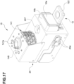
- Fig. 16 to 23 depict another embodiment of the invention. This embodiment is similar to the one described above, both in structure and operation. Elements corresponding to those of the foregoing embodiment have been assigned the same numerical references. These elements will not be further described.
- Fig. 16 and 19 show a condition in which the first assembly part 12 is fully extracted from the cavity 16.
- Fig. 18 and 21 show a condition in which the first assembly part 12 is in an insertion end position.
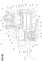
- Fig. 17 , 20 , 22 , and 23 show the first assembly part 12 in an intermediate position, more precisely in the detection position.
- the optical sensor is shown schematically only in Fig. 20 , while the related movable closure element is not shown in Fig. 16-23 . However, this movable closure element is positioned at the window 207, in a manner similar to the closure element 45 of the preceding embodiment.
- Fig. 16-23 Also shown in Fig. 16-23 is a part of the driving mechanism for the movable closure element, represented by sliders shown again with the reference 45a.
- the first assembly part 12 comprises a partition 12a formed between the main portion 121 and the handle 122 of the first assembly part 12 and extending upward from the first assembly part 12.
- a screen 16b is arranged at the insertion opening 16a of the support structure 20, this screen being formed so as to partially surround the insertion opening 16a, in particular an upper portion of the insertion opening 16a.
- the screen 16b may not be required.
- Such a closure interrupts the input of light that varies with ambient conditions during acquisition, resulting in controlled and repeatable lighting conditions, which may be provided by a lighting system (not shown) associated with the optical sensor 40 and controllable to light the interior to the cavity 16.
- a lighting system (not shown) associated with the optical sensor 40 and controllable to light the interior to the cavity 16.
Landscapes
- Engineering & Computer Science (AREA)
- Food Science & Technology (AREA)
- Apparatus For Making Beverages (AREA)
- External Artificial Organs (AREA)
- Infusion, Injection, And Reservoir Apparatuses (AREA)
- Medical Preparation Storing Or Oral Administration Devices (AREA)
- Soy Sauces And Products Related Thereto (AREA)
Applications Claiming Priority (3)
| Application Number | Priority Date | Filing Date | Title |
|---|---|---|---|
| IT102020000014434A IT202000014434A1 (it) | 2020-06-17 | 2020-06-17 | Unità d'infusione |
| PCT/IB2021/055321 WO2021255669A1 (en) | 2020-06-17 | 2021-06-16 | A brewing unit |
| EP21732993.7A EP4167808A1 (de) | 2020-06-17 | 2021-06-16 | Brüheinheit |
Related Parent Applications (1)
| Application Number | Title | Priority Date | Filing Date |
|---|---|---|---|
| EP21732993.7A Division EP4167808A1 (de) | 2020-06-17 | 2021-06-16 | Brüheinheit |
Publications (2)
| Publication Number | Publication Date |
|---|---|
| EP4406460A2 true EP4406460A2 (de) | 2024-07-31 |
| EP4406460A3 EP4406460A3 (de) | 2024-11-06 |
Family
ID=72644570
Family Applications (2)
| Application Number | Title | Priority Date | Filing Date |
|---|---|---|---|
| EP24180106.7A Pending EP4406460A3 (de) | 2020-06-17 | 2021-06-16 | Brüheinheit |
| EP21732993.7A Pending EP4167808A1 (de) | 2020-06-17 | 2021-06-16 | Brüheinheit |
Family Applications After (1)
| Application Number | Title | Priority Date | Filing Date |
|---|---|---|---|
| EP21732993.7A Pending EP4167808A1 (de) | 2020-06-17 | 2021-06-16 | Brüheinheit |
Country Status (10)
| Country | Link |
|---|---|
| US (1) | US20230165400A1 (de) |
| EP (2) | EP4406460A3 (de) |
| JP (2) | JP7682926B2 (de) |
| KR (1) | KR20230026990A (de) |
| CN (2) | CN121242393A (de) |
| AU (1) | AU2021294004A1 (de) |
| BR (1) | BR112022022217A2 (de) |
| CA (1) | CA3176377A1 (de) |
| IT (1) | IT202000014434A1 (de) |
| WO (1) | WO2021255669A1 (de) |
Family Cites Families (12)
| Publication number | Priority date | Publication date | Assignee | Title |
|---|---|---|---|---|
| DE4212288A1 (de) * | 1992-04-11 | 1993-10-14 | Braun Ag | Brüheinrichtung für eine Haushalts-Espressomaschine |
| FR2873011B1 (fr) * | 2004-07-16 | 2007-12-14 | Reneka Internat Sarl | Groupe de preparation d'au moins une tasse de cafe de type expresso ou autre boisson chaude a partir d'une dose individuelle preemballee appelee dosette |
| JP4898825B2 (ja) * | 2005-11-22 | 2012-03-21 | コーニンクレッカ フィリップス エレクトロニクス エヌ ヴィ | コーヒーの製造装置 |
| EP2244616B1 (de) * | 2008-02-05 | 2014-11-05 | Luigi Lavazza S.p.A. | Getränkemaschine mit vorrichtung zum laden und entladen von kartuschen |
| US8663724B1 (en) * | 2010-03-03 | 2014-03-04 | Food Equipment Technologies Company, Inc. | Automated beverage brewing method |
| ITMI20121081A1 (it) * | 2012-06-20 | 2013-12-21 | Fas International Spa | Gruppo erogatore di polveri per distributori automatici per la preparazione di bevande. |
| CA2964311A1 (en) * | 2014-10-14 | 2016-04-21 | Ides Development Company Limited | Infusion group for machines for the dispensing of beverages in the form of infusion |
| ITUA20162351A1 (it) * | 2016-04-06 | 2017-10-06 | Lavazza Luigi Spa | Gruppo di infusione, macchina e sistema per la preparazione di una bevanda con l'impiego di capsule preconfezionate. |
| IT201600126287A1 (it) * | 2016-12-14 | 2018-06-14 | Caffitaly System Spa | Apparecchiatura per la preparazione di una bevanda tramite infusione di una sostanza alimentare con acqua |
| EP3653087B1 (de) * | 2017-07-10 | 2023-05-24 | Guangdong Midea Consumer Electric Manufacturing Co., Ltd. | Verriegelungsbrühvorrichtung, getränkebrühvorrichtung und getränkeautomat |
| CN108478009A (zh) * | 2018-06-19 | 2018-09-04 | 深圳市三维远东科技有限公司 | 真空萃取冲泡系统 |
| EP3873304A1 (de) * | 2018-11-01 | 2021-09-08 | Société des Produits Nestlé S.A. | Kapselsystem mit erkennungsmittel und anpassbarem öffnungs- und injektionsmechanismus |
-
2020
- 2020-06-17 IT IT102020000014434A patent/IT202000014434A1/it unknown
-
2021
- 2021-06-16 CN CN202511722725.6A patent/CN121242393A/zh active Pending
- 2021-06-16 BR BR112022022217A patent/BR112022022217A2/pt unknown
- 2021-06-16 EP EP24180106.7A patent/EP4406460A3/de active Pending
- 2021-06-16 JP JP2022567290A patent/JP7682926B2/ja active Active
- 2021-06-16 AU AU2021294004A patent/AU2021294004A1/en active Pending
- 2021-06-16 US US17/997,987 patent/US20230165400A1/en active Pending
- 2021-06-16 EP EP21732993.7A patent/EP4167808A1/de active Pending
- 2021-06-16 CA CA3176377A patent/CA3176377A1/en active Pending
- 2021-06-16 WO PCT/IB2021/055321 patent/WO2021255669A1/en not_active Ceased
- 2021-06-16 KR KR1020227038820A patent/KR20230026990A/ko active Pending
- 2021-06-16 CN CN202180033021.1A patent/CN115551395B/zh active Active
-
2025
- 2025-05-14 JP JP2025081120A patent/JP2025122034A/ja active Pending
Also Published As
| Publication number | Publication date |
|---|---|
| WO2021255669A1 (en) | 2021-12-23 |
| CN115551395A (zh) | 2022-12-30 |
| AU2021294004A1 (en) | 2022-11-24 |
| KR20230026990A (ko) | 2023-02-27 |
| JP7682926B2 (ja) | 2025-05-26 |
| US20230165400A1 (en) | 2023-06-01 |
| CA3176377A1 (en) | 2021-12-23 |
| CN121242393A (zh) | 2026-01-02 |
| IT202000014434A1 (it) | 2021-12-17 |
| CN115551395B (zh) | 2025-12-12 |
| EP4167808A1 (de) | 2023-04-26 |
| JP2023530818A (ja) | 2023-07-20 |
| BR112022022217A2 (pt) | 2022-12-27 |
| EP4406460A3 (de) | 2024-11-06 |
| JP2025122034A (ja) | 2025-08-20 |
Similar Documents
| Publication | Publication Date | Title |
|---|---|---|
| CN100369570C (zh) | 物质榨取装置 | |
| EP2717749B1 (de) | Ausgabevorrichtung für maschinen zur erzeugung flüssiger produkte mittels patronen | |
| US8881643B2 (en) | Infusion unit for drinks with washing system | |
| EP2961296B1 (de) | Infusionsvorrichtung zur herstellung eines heissgetränks | |
| US12616331B2 (en) | Motorized brewing unit | |
| KR20090026811A (ko) | 음료수 조제 기계용 주입 조립체 | |
| EP2674081A1 (de) | Infusionsgruppe | |
| CN113993428A (zh) | 用于制备咖啡的机器 | |
| US20230165400A1 (en) | A brewing unit | |
| US20250344898A1 (en) | Coffee brewing apparatus | |
| IT202100024806A1 (it) | Apparecchiatura per la preparazione di una bevanda tramite infusione di una sostanza alimentare |
Legal Events
| Date | Code | Title | Description |
|---|---|---|---|
| PUAI | Public reference made under article 153(3) epc to a published international application that has entered the european phase |
Free format text: ORIGINAL CODE: 0009012 |
|
| STAA | Information on the status of an ep patent application or granted ep patent |
Free format text: STATUS: THE APPLICATION HAS BEEN PUBLISHED |
|
| AC | Divisional application: reference to earlier application |
Ref document number: 4167808 Country of ref document: EP Kind code of ref document: P |
|
| AK | Designated contracting states |
Kind code of ref document: A2 Designated state(s): AL AT BE BG CH CY CZ DE DK EE ES FI FR GB GR HR HU IE IS IT LI LT LU LV MC MK MT NL NO PL PT RO RS SE SI SK SM TR |
|
| PUAL | Search report despatched |
Free format text: ORIGINAL CODE: 0009013 |
|
| AK | Designated contracting states |
Kind code of ref document: A3 Designated state(s): AL AT BE BG CH CY CZ DE DK EE ES FI FR GB GR HR HU IE IS IT LI LT LU LV MC MK MT NL NO PL PT RO RS SE SI SK SM TR |
|
| RIC1 | Information provided on ipc code assigned before grant |
Ipc: A47J 31/44 20060101AFI20240927BHEP |
|
| STAA | Information on the status of an ep patent application or granted ep patent |
Free format text: STATUS: REQUEST FOR EXAMINATION WAS MADE |
|
| 17P | Request for examination filed |
Effective date: 20250430 |