EP4406450A2 - Kombinationshaarstylingvorrichtung mit positionierbaren heizplattenabdeckungen - Google Patents
Kombinationshaarstylingvorrichtung mit positionierbaren heizplattenabdeckungen Download PDFInfo
- Publication number
- EP4406450A2 EP4406450A2 EP24154436.0A EP24154436A EP4406450A2 EP 4406450 A2 EP4406450 A2 EP 4406450A2 EP 24154436 A EP24154436 A EP 24154436A EP 4406450 A2 EP4406450 A2 EP 4406450A2
- Authority
- EP
- European Patent Office
- Prior art keywords
- heating
- heating plate
- hair styling
- arms
- styling apparatus
- Prior art date
- Legal status (The legal status is an assumption and is not a legal conclusion. Google has not performed a legal analysis and makes no representation as to the accuracy of the status listed.)
- Pending
Links
Images







Classifications
-
- A—HUMAN NECESSITIES
- A45—HAND OR TRAVELLING ARTICLES
- A45D—HAIRDRESSING OR SHAVING EQUIPMENT; EQUIPMENT FOR COSMETICS OR COSMETIC TREATMENTS, e.g. FOR MANICURING OR PEDICURING
- A45D1/00—Curling-tongs, i.e. tongs for use when hot; Curling-irons, i.e. irons for use when hot; Accessories therefor
- A45D1/02—Curling-tongs, i.e. tongs for use when hot; Curling-irons, i.e. irons for use when hot; Accessories therefor with means for internal heating, e.g. by liquid fuel
- A45D1/04—Curling-tongs, i.e. tongs for use when hot; Curling-irons, i.e. irons for use when hot; Accessories therefor with means for internal heating, e.g. by liquid fuel by electricity
-
- A—HUMAN NECESSITIES
- A45—HAND OR TRAVELLING ARTICLES
- A45D—HAIRDRESSING OR SHAVING EQUIPMENT; EQUIPMENT FOR COSMETICS OR COSMETIC TREATMENTS, e.g. FOR MANICURING OR PEDICURING
- A45D1/00—Curling-tongs, i.e. tongs for use when hot; Curling-irons, i.e. irons for use when hot; Accessories therefor
- A45D1/06—Curling-tongs, i.e. tongs for use when hot; Curling-irons, i.e. irons for use when hot; Accessories therefor with two or more jaws
-
- A—HUMAN NECESSITIES
- A45—HAND OR TRAVELLING ARTICLES
- A45D—HAIRDRESSING OR SHAVING EQUIPMENT; EQUIPMENT FOR COSMETICS OR COSMETIC TREATMENTS, e.g. FOR MANICURING OR PEDICURING
- A45D2/00—Hair-curling or hair-waving appliances ; Appliances for hair dressing treatment not otherwise provided for
- A45D2/001—Hair straightening appliances
-
- A—HUMAN NECESSITIES
- A45—HAND OR TRAVELLING ARTICLES
- A45D—HAIRDRESSING OR SHAVING EQUIPMENT; EQUIPMENT FOR COSMETICS OR COSMETIC TREATMENTS, e.g. FOR MANICURING OR PEDICURING
- A45D6/00—Details of, or accessories for, hair-curling or hair-waving devices
-
- A—HUMAN NECESSITIES
- A45—HAND OR TRAVELLING ARTICLES
- A45D—HAIRDRESSING OR SHAVING EQUIPMENT; EQUIPMENT FOR COSMETICS OR COSMETIC TREATMENTS, e.g. FOR MANICURING OR PEDICURING
- A45D1/00—Curling-tongs, i.e. tongs for use when hot; Curling-irons, i.e. irons for use when hot; Accessories therefor
- A45D2001/002—Accessories therefor
Definitions
- the present disclosure relates generally to a hair styling apparatus and, more particularly, to a hair styling apparatus including positionable heating plate covers that facilitate the hair styling apparatus operating in a straightener mode and/or a curling wand mode.
- Traditional hair styling apparatuses have a pair of arms that are hingedly connected to permit manual opening and closing of the arms relative to one another for clamping hair between the arms and straightening or curling the hair.
- Each arm typically includes a hair heating surface that is heated during a styling operation. During use, hair is positioned between the hair heating surfaces and the hair is styled. Since traditional hair stylers perform either straightening or curling, a user must use two separate hair styling apparatuses to satisfy both their straightening and curling needs.
- the present disclosure describes a hair styling apparatus and, more particularly, a combination hair styling apparatus capable of selectively switching between a straightener mode and a curling wand mode.
- a hair styling apparatus in one embodiment, includes first and second arms each having first and second ends.
- the first and second arms may be pivotably coupled to each other at least at the first ends of the arms for selective, pivotal movement relative to each other to selectively configure the hair styling apparatus between an opened position and a closed position.
- the hair styling apparatus also includes a first pair of heating plates, and each of the first heating plates define a hair contact surface. Each of the first heating plates is connected to an inner portion of the first and second arms.
- the hair styling apparatus also includes a second pair of heating plates, and each of the second heating plates define a hair contact surface. Each of the second heating plates may be connected to an outer portion of the first and second arms.
- the hair styling apparatus may also include a pair of heating plate covers, and each of the heating plate covers may be connected to each of the second heating plates.
- Each of the heating plate covers is slidably movable between a first position and a second position. The first position covers a corresponding second heating plate and the second position exposes the corresponding second heating plate for use.
- Each of the first and second arms may include a heating element connected to the first and second heating plates and configured to heat the first and second heating plates.
- each of the first and second arms may include a first heating element connected to the first heating plates and a second heating element connected to the second heating plates.
- the hair styling apparatus may further include at least one switch.
- the at least one switch may activate/deactivate either the first pair of heating plates or the second pair of heating plates when at least one of the heating plate covers is in the first position, the second position, or moves between the first position and the second position.
- each of the first and second arms of the hair styling apparatus may define a slot.
- the slot may be configured to receive at least a portion of the corresponding heating plate cover such that the heating plate cover is slidable between the first position and the second position.
- a switch may be positioned in the slot of the first arm such that the heating plate cover connected to the first arm engages with the switch when sliding between the first position and the second position.
- each of the first and second arms may define a first slot and a second slot.
- the first and second slots may be oppositely positioned from each other.
- the first and second slots may be configured to each receive at least a portion of the corresponding heating plate cover such that the heating plate cover is slidable between the first position and the second position.
- a slot switch may be positioned in the first slot of the first arm such that the corresponding heat plate cover engages with the slot switch to activate/deactivate the pair of second heating plates when sliding between the first position and the second position.
- the hair styling apparatus may include an arm switch on an outer surface of either the first arm or the second arm.
- the corresponding heat plate cover may engage with the arm switch when sliding between the first position and the second position.
- activation of the first pair of heating plates and the second pair of heating plates is selectable based on at least the configuration of the first and second arms. For example, opening and closing the first and second arms activates and deactivates the first pair of heating plates. Then, closing the first and second arms and sliding the heating plate covers toward the second position activates the second pair of heating plates and sliding the heating plate covers toward the first position deactivates the second pair of heating plates.
- the heating plate covers may define flared ends that are flared outwardly from the first and second arms.
- the heating plate covers may also define heat mitigation slots configured to facilitate removal of heat from at least the second pair of heating plates.
- the hair styling apparatus may further include a locking mechanism connected to the first arm and a receiving mechanism connected to the second arm.
- the locking mechanism may removably engage with the receiving mechanism to secure the first and second arms in the closed position.
- a hair styling apparatus in yet another embodiment, includes a first arm having a first heating surface, a second heating surface, and a first grip and a second arm having a third heating surface, a fourth heating surface, and a second grip.
- the first and second arms may be pivotably coupled to each other for selective, pivotal movement relative to each other to selectively configure the hair styling apparatus between an opened position and a closed position.
- the first heating surface and the third heating surface may be configured to clamp hair therebetween when the first and second arms are in the closed position.
- the second heating surface and the fourth heating surface may be positioned to engage hair wrapped around an exterior of the hair styling apparatus.
- the hair styling apparatus may include a first heating plate cover which may be connected to the first arm and a second heating plate cover which may be connected to the second arm.
- Each of the first and second heating plate covers may be movable between a first position and a second position. In the first position, the first and second heating plate covers extend over the second and fourth heating surfaces. In the second position, the first and second heating plate covers extend over the first grip and the second grip and expose the second and fourth heating surfaces.
- each of the first and second arms may define a first slot and a second slot.
- the first and second slots may be oppositely positioned from each other.
- the first and second slots may be configured to each receive at least a portion of the corresponding heating plate cover such that the heating plate cover is slidable between the first position and the second position.
- a slot switch may be positioned relative to the first slot of the first arm. The corresponding heat plate cover may engage with the slot switch to activate/deactivate the pair of second heating plates when the heat plate cover slides between the first position and the second position.
- each of the first and second arms may include a first heating element connected to the first heating plates and a second heating element connected to the second heating plates.
- a hair styling apparatus in yet another embodiment, includes first and second arms each having first and second ends.
- the first and second arms may be pivotably coupled to each other at least at the first end of the arm for selective, pivotal movement relative to each other to selectively configure the hair styling apparatus between an opened position and a closed position.
- the first and second arms each may define a first slot and a second slot. The first and second slots may be oppositely positioned from each other.
- the hair styling apparatus may include a first pair of heating plates. Each of the first heating plates may have a hair contact surface. Each of the first heating plates may be connected to an inner portion of the first and second arms.
- the hair styling apparatus may include a second pair of heating plates. Each of the second heating plates may have a hair contact surface. Each of the second heating plates may be connected to an outer portion of the first and second arms.
- the hair styling apparatus may include a pair of heating plate covers. Each of the heating plate covers may be connected to each of the second heating plates. Each of the heating plate covers may be movable between a first position and a second position. In some instances, the first position may cover a corresponding second heating plate and the second position may expose the corresponding second heating plate for use. In some instances, the first and second slots may be configured to each receive at least a portion of the corresponding heating plate cover such that the heating plate cover is slidable between the first position and the second position.
- the hair styling apparatus may include a slot switch that may be positioned relative to the first slot. The corresponding heat plate cover may engage with the slot switch when sliding between the first position and the second position such that the slot switch activates/deactivates the pair of second heating plates.
- the hair styling apparatus may further include an arm switch connected to either the first arm or the second arm.
- the corresponding heat plate cover may engage with the slot switch and the arm switch when sliding between the first position and the second position.
- the slot switch and/or the arm switch may be a pressure switch.
- the hair styling apparatus may also include a user interface.
- the user interface may include at least one of a display, a temperature control, an ON/OFF switch, a heating plate indicator configured to indicate which of the first and second heating plates is activated, and combinations thereof.
- the hair styling apparatus may also include a locking mechanism connected to the first arm and a receiving mechanism connected to the second arm.
- the locking mechanism may removably engage with the receiving mechanism to open or close the first and second arms such that the locking mechanism is configured to override the function of the slot switches.
- the heating plate covers may be used to assist in the straightening hair mode by cooling the hair as it passes over the heating plate cover.
- hair styler and “hair styling apparatus” may be used interchangeably without departing from the spirit/scope of this disclosure.
- the term "about” refers to a measurable value such as a parameter, an amount, a temporal duration, and the like and is meant to include variations of +/- 15% or less, preferably variations of +/- 10% or less, more preferably variations of +/- 5% or less, even more preferably variations of +/- 1% or less, and still more preferably variations of +/- 0.1% or less of and from the particularly recited value, in so far as such variations are appropriate to perform in the invention described herein. Furthermore, it is also to be understood that the value to which the modifier "about” refers is itself specifically disclosed herein.
- spatially relative terms such as “beneath”, “below”, “lower”, “above”, “upper”, “front”, “back”, “side”, “left”, “right”, “rear”, and the like, are used for ease of description to describe one element or feature's relationship to another element(s) or feature(s). It is further understood that the terms “front”, “back”, “left”, “right”, “top”, and “bottom” are not intended to be limiting and are intended to be interchangeable, where appropriate. Further, it should be noted that the terms “first,” “second,” and the like herein do not denote any order, quantity, or relative importance, but rather are used to distinguish one element from another.
- configure(s) refer to the capability of a component and/or assembly, but do not preclude the presence or addition of other capabilities, features, components, elements, operations, and any combinations thereof.
- any combination or permutation of features, functions and/or embodiments as disclosed herein is envisioned.
- the hair styling apparatus according to any of the embodiments described above may contain any or all of the optional features of the hair styling apparatus described herein (at least to the extent they are not mutually incompatible).
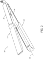
- a hair styling apparatus 10 includes a pair of arms (e.g., an upper arm 12 and a lower arm 14), a hinge 16 by which upper arm 12 and lower arm 14 are connected, and a power cord 18 (e.g., partially illustrated in the figures).
- Each arm 12, 14 includes a first end and a second end. Arms 12, 14 are pivotably coupled to each other at the first ends of the arms 12, 14 by hinge 16. Hinge 16 is configured to facilitate opening and closing of arms 12, 14 relative to one another.
- Hair styling apparatus 10 has a longitudinal axis 60 extending through hinge 16 (e.g., Fig. 3 ). Arms 12, 14 extend along longitudinal axis 60 when arms 12, 14 are in the closed position.
- Hinge 16 may include a locking mechanism to lock arms 12, 14 in a desired position (e.g., an open position, a closed position, and an intermediate position).
- the intermediate position may be a desired position between the closed position and open position.
- Hinge 16 may operate in combination with a biasing mechanism (e.g., a spring) to facilitate opening or closing of hair styling apparatus 10.
- hair styling apparatus 10 may include a power button (or “ON/OFF” switch), a temperature increase button (or “UP” switch), and a temperature decrease button (or “DOWN” switch).
- hair styling apparatus 10 may be configured in any manner that facilitates user operation of hair styling apparatus 10 as set forth herein (e.g., hair styling apparatus 10 may have any suitable number of buttons and displays arranged in any suitable manner).
- hair styling apparatus 10 may include a graphical user interface (e.g., an LCD display) 152 (see Fig. 6 ). Hair styling apparatus 10 may also include a temperature indicator to display the current and/or desired temperature.
- Hair styling apparatus 10 may also include a mode selector (e.g., selection of a straightening mode or a curling mode).
- the mode selector may also include a power selection (e.g., selection of an "OFF/ON" mode or a "High/Low” mode).
- Hair styling apparatus 10 may also include a mode indicator that displays which of the modes is selected.
- hair styling apparatus 10 may include a plurality of buttons 154 (or similar functioning elements, e.g., toggles, switches, IR), the plurality of buttons 154 may control temperature, mode, power, and combinations thereof (see Fig. 6 ).
- a user may first select which mode is desired (e.g., a straightening mode, a curling mode). Selection of the desired mode may be accomplished by a variety of ways including, adjusting a switch/selector, opening/closing arms 12, 14, exposing desired heating plates, and combinations thereof.
- upper arm 12 includes an upper grip 20 and an upper clamp head 22.
- Upper clamp head 22 defines inner upper heating area 24 and outer upper heating area 26. Inner upper heating area 24 is opposite from outer upper heating area 26.
- Upper clamp head 22 includes inner upper heating plate 28 positioned within inner upper heating area 24. Inner upper heating plate 28 further defines inner upper hair heating surface 30. Inner upper hair heating surface 30 may be planar, curved, twisted, and combinations thereof.
- Upper clamp head 22 includes upper heating plate cover 32 positioned within outer upper heating area 26.
- Upper clamp head 22 includes outer upper heating plate 29 positioned within outer upper heating area 26.
- Outer upper heating plate 29 further defines outer upper hair heating surface 31. In the example, outer upper hair heating surface 31 is curved. However, outer upper hair heating surface 31 may be planar, curved, twisted, and combinations thereof.
- Heating plate cover 32 is connected to outer upper heating plate 29. Heating plate cover 32 is movably connected to outer upper heating plate 29. Heating plate cover 32 may define an inner surface that is similar to the outer surface of at least hair heating surface. For example, heating plate cover 32 may define an inner curved surface. In some instances, heating plate cover 32 may define a lateral cross-section that is curved. However, it should be understood that heating plate cover 32 may define an inner surface that is a variety of shapes, without departing from the spirit/scope of this disclosure.
- Lower arm 14 includes a lower grip 34 and a lower clamp head 36.
- Lower clamp head 36 defines an inner lower heating area 38 and an outer lower heating area 40.
- Inner lower heating area 38 is opposite from outer lower heating area 40.
- Lower clamp head 36 includes an inner lower heating plate 42 positioned within inner lower heating area 38.
- Inner lower heating plate 42 further defines an inner lower hair heating surface 44.
- Inner lower hair heating surface 44 may be planar, curved, twisted, and combinations thereof.
- inner lower hair heating surface 44 is planar.
- Lower clamp head 36 includes a lower heating plate cover 46 positioned within outer lower heating area 40.
- Lower clamp head 36 includes an outer lower heating plate 43 positioned within outer lower heating area 40.
- Outer lower heating plate 43 further defines an outer lower hair heating surface 45.
- outer upper hair heating surface 31 is curved.
- outer lower hair heating surface 45 may be planar, curved, twisted, and combinations thereof.
- Heating plate cover 46 is connected to outer lower heating plate 43. Heating plate cover 46 is movably connected to outer lower heating plate 43. Heating plate cover 46 defines an inner surface that is similar to the outer surface of at least hair heating surface. For example, heating plate cover 46 defines an inner curved surface. In some instances, heating plate cover 46 defines a lateral cross-section that is curved. However, it should be understood that heating plate cover 46 may define an inner surface that is a variety of shapes, without departing from the spirit/scope of this disclosure.
- Upper clamp head 22 includes a tip 66.
- Lower clamp head 36 includes a tip 68.
- Tips 66, 68 are positioned at second ends of arms 12, 14 opposite from the first ends where power cord 18 extends outwardly from hair styling apparatus 10.
- Tips 66, 68 may be positioned on either side of longitudinal axis 60 such that longitudinal axis 60 extends between tips 66, 68.
- Tips 66, 68 are manufactured from a material that does not substantially increase in temperature when one or more heating plate 28, 29, 42, 43 is active.
- Tips 66, 68 are at least partially manufactured from a material with a low thermal conductivity (e.g., rubber, plastic).
- Tip 66, 68 are flared outwardly. For example, tips 66, 68 are flared in a direction away from longitudinal axis 60. A user may grip tips 66, 68 so as to maneuver and/or spin hair styling apparatus 10 without touching heating plates 28, 29, 42, 43.
- hair styling apparatus 10 includes upper arm 12 and lower arm 14, each arm defining at least two heating areas (e.g., inner heating area 24, 38 and outer heating area 26, 40).
- Inner heating area 24, 38 and outer heating area 26, 40 may be utilized to perform various hair styling tasks (e.g., straightening, curling, and combinations thereof).
- inner heating plates 28, 42 alone or in combination, may be utilized to perform various hair styling tasks (e.g., straightening, curling, and combinations thereof).
- outer heating plates 29, 43 alone or in combination, may be utilized to perform various hair styling tasks (e.g., straightening, curling, and combinations thereof).
- outer heating plates 29, 43 may be deactivated. In other instances, when inner heating plates 28, 42 are deactivated, outer heating plates 29, 43 may be activated. In other instances, when inner heating plates 28, 42 are activated, outer heating plates 29, 43 may be activated.
- heating plate cover 32, 46 at least partially covers outer heating plate 29, 43.
- upper heating plate cover 32 completely covers outer upper hair heating surface 31 of outer upper heating plate 29.
- upper heating plate cover 32 may cover outer upper hair heating surface 31 and at least partially cover tip 66.
- upper heating plate cover 32 may substantially cover outer upper hair heating surface 31 and tip 66.
- Lower heating plate cover 46 at least partially covers outer lower hair heating surface 45 of outer lower heating plate 43.
- lower heating plate cover 46 may cover outer lower hair heating surface 45 and at least partially cover tip 68.
- lower heating plate cover 46 may substantially cover outer lower hair heating surface 45 and tip 68.
- heating plate cover 32, 46 covers heating plate 29, 43 such that hair heating surface 31, 45 of outer heating plate 29, 43 is "shielded".
- shielding refers to inhibiting contact, either directly or indirectly, with a surface.
- shielding of hair heating surface 31, 45 of outer heating plate 29, 43 may ensure a user does not inadvertently burn themselves, in the event the outer heating plate 29, 43 are hot but not intended for use.
- Heating plate cover 32, 46 may be configured to limit heat conduction.
- heating plate cover 32, 46 may be at least partially manufactured from a material with a low thermal conductivity (e.g., rubber, plastic). Heating plate covers 32, 46 may be manufactured from a material that does not substantially increase in temperature when one or more heating plate 28, 29, 42, 43 is active,
- Heating plate covers 32, 46 are movably positioned relative to outer heating plates 29, 43.
- heating plate covers 32, 46 are slidably engaged with arms 12, 14 such that each heating plate cover 32, 46 moves between a first position and a second position.
- Heating plate cover 32, 46 may slide between the first position and the second position to at least partially expose hair heating surface 31, 45 of outer heating plate 29, 43 or at least partially conceal outer hair heating surface 31, 45 of heating plate 29, 43.
- Heating plate covers 32, 46 may slide between the first position and the second position to expose hair heating surface 31, 45 of outer heating plate 29, 43 or conceal hair heating surface 31, 45 of outer heating plate 29, 43.
- heating plate covers 32, 46 in the second position may lock arms 12, 14 in the closed position such that arms 12, 14 cannot be opened when heating plate 29, 43 are exposed.
- Heating plate covers 32, 46 may slide between the first position and the second position along longitudinal axis 60.
- heating plate covers 32, 46 may include a protrusion to engage directly or indirectly with arms 12, 14 to facilitate movement between the first position and the second position.
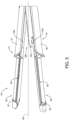
- Upper heating plate cover 32 includes upper heating plate cover protrusion 52 and is movably (e.g., slidably) engaged with an upper slot 48 of arm 12.
- Upper slot 48 extends between upper tip 66 and the first end of arm 12.
- power cord 18 extends outwardly from the first end of arm 12.
- Upper slot 48 extends along longitudinal axis 60.
- Upper slot 48 may extend parallel to longitudinal axis 60 between upper tip 66 and first end of arm 12.
- Lower heating plate cover 46 includes lower heating plate cover protrusion 54 and is movably (e.g., slidably) engaged with a lower slot 50 of arm 14.
- Lower slot 50 may extend between lower tip 68 and first end of arm 14.
- Lower slot 50 may extend along longitudinal axis 60.
- lower slot 50 may extend parallel to longitudinal axis 60 between lower tip 68 and the first end of arm 14.
- arm 12 may define at least two upper slots 48 and arm 14 may define at least two lower slots 50.
- the two upper slots 48 may extend between upper tip 66 and the first end of arm 12 along longitudinal axis 60.
- the two lower slots 50 may extend between lower tip 68 and the first end of arm 14 along longitudinal axis 60.
- the two upper slots 48 may be defined oppositely from each other along arm 12. For example, if one of the two upper slots 48 is positioned at 0 degrees, the second of the two upper slots 48 may be positioned at 180 degrees relative to the other upper slot 48.
- the two upper slots 48 may be positioned in a variety of locations around arm 12 and along longitudinal axis 60 so as to guide heating plate cover protrusion 52 of heating plate cover 32 between the first position and the second position.
- the two lower slots 50 may be defined oppositely from each along arm 14. For example, if one of the two lower slots 50 is positioned at 0 degrees, the second of the two lower slots 50 may be positioned at 180 degrees relative to the other lower slot 50. However, it should be understood that the two lower slots 50 may be positioned in a variety of locations around arm 14 and along longitudinal axis 60 so as to guide heating plate cover protrusion 54 of heating plate cover 46 between the first position and the second position.
- upper heating plate cover 32 may be positioned near upper tip 66 and may slide in a direction parallel to the longitudinal axis and toward/away from the first end of arm 12(e.g., the end of hair styling apparatus 10 where power cord 18 extends from). In some examples, upper heating plate cover 32 may be positioned to substantially cover upper tip 66 and may slide in a direction parallel to the longitudinal axis and toward/away from the first end of arm 12(e.g., the end of hair styling apparatus 10 where power cord 18 extends from).
- lower heating plate cover 46 may be positioned near lower tip 68 and may slide in a direction parallel to the longitudinal axis and toward/away from the first end of arm 14(e.g., the end of hair styling apparatus 10 where power cord 18 extends from). In some examples, lower heating plate cover 46 may substantially cover lower tip 68 and may slide in a direction parallel to the longitudinal axis and toward/away from the first end of arm 14(e.g., the end of hair styling apparatus 10 where power cord 18 extends from). Upper heating plate cover 32 and lower heating plate cover 46 move independently of one another. In other examples, upper heating plate cover 32 and lower heating plate cover 46 may move in combination with one another.
- Heating plate cover 32 includes upper flared end 33 and lower flared end 47.
- Heating plate cover 46 includes upper flared end 35 and lower flared end 49. In some embodiments, heating plate cover 32 and/or heating plate cover 46 may only include one flared end.
- Upper heating plate cover flared end 33 flares outwardly and, when in the closed position, is positioned near upper tip 66.
- Upper heating plate cover flared end 35 flares outwardly and is positioned opposite upper heating plate cover flared end 33.
- Lower heating plate cover flared end 47 flares outwardly and, when in the closed position, is positioned near lower tip 68.
- Lower heating plate cover flared end 49 flares outwardly and is positioned opposite lower heating plate cover flared end 47.
- Upper flared end 33, 35 and lower flared end 47, 49 facilitate a user grasping heating plate covers 32, 46 and allow a user to easily move heating plate covers 32, 46 between the first position and the second position.
- Upper flared ends 33, 35 and lower flared ends 47, 49 may include other features to assist a user with gripping heating plate cover 32, 46.
- Heating plate covers 32, 46 are permanently attached to arms 12, 14 such that heating plate cover 32, 46 may not be removable. Accordingly, hair styling apparatus 10 is switched between modes without removing heating plate covers 32, 46. As a result, heating plate covers 32, 46 remain attached to the hair styling apparatus 10 at all times and will not be misplaced or lost. In addition, the heating plate covers 32, 46 are simpler to switch between modes than shields that are removed and reattached in different modes. In other instances, heating plate covers 32, 46 may be removably attached to arms 12, 14eating plate cover. In either configuration, heating plate cover 32, 46 may be movable relative to arms 12, 14. For example, heating plate cover 32, 46 may be slidable between a first position and a second position relative to arms 12, 14.
- Hair styling apparatus 10 further includes at least one switch, button, touchscreen, and/or user interface configured to activate/deactivate at least one heating plate.
- hair styling apparatus 10 includes a switch configured to activate/deactivate inner upper heating plate 28 and inner lower heating plate 42.
- hair styling apparatus 10 may include a first switch configured to activate/deactivate inner upper heating plate 28 and a second switch configured to activate/deactivate inner lower heating plate 42. The switch or plurality of switches may be configured to activate heating plate 28, 42 when arms 12, 14 are opened and deactivate heating plate 28, 42 when arms 12, 14 are closed.
- Hair styling apparatus 10 includes a switch, button, touchscreen, and/or user interface configured to activate/deactivate at least one outer heating plate 29, 43.
- hair styling apparatus 10 includes a switch configured to activate/deactivate outer upper heating plate 29 and outer lower heating plate 43.
- hair styling apparatus 10 may include a first switch configured to activate/deactivate outer upper heating plate 29 and a second switch configured to activate/deactivate outer lower heating plate 43.
- the switch or plurality of switches may be configured to activate heating plate 29, 43 when heating plate cover 32, 46 are moved (e.g., slid) in a first direction and deactivate heating plate 29, 43 when heating plate cover 32, 46 are moved (e.g., slid) in a second direction.
- hair styling apparatus 10 may include a plurality of switches configured to activate/deactivate, alone or in combination, outer upper heating plate 29 and outer lower heating plate 43.
- hair styling apparatus 10 includes at least one slot switch 62 mounted within upper slot 48 and at least one slot switch 62 mounted within lower slot 50. Slot switches 62 are positioned along the path of heating plate covers 32, 46 within slots 48, 50 such that heating plate covers 32, 46 contact slot switches 62 when heating plate covers 32, 46 are moved between the first position and the second position.
- Hair styling apparatus 10 may further include at least one arm switch 64 configured to activate/deactivate, alone or in combination with slot switch 62, outer upper heating plate 29 and outer lower heating plate 43. Arm switch 64 may prevent accidental activation of heating plate 29, 43.
- hair styling apparatus 10 may include at least two slot switches 62 mounted within upper slot 48 and at least two slot switches mounted within lower slot 50.
- the at least two switches 62 mounted within upper slot 48 may be oppositely positioned.
- first slot switch 62 may be positioned near upper tip 66 and second slot switch 62 may be positioned near the first end of arm 12.
- the at least two switches 62 connected to lower slot 50 may be oppositely positioned.
- first slot switch 62 may be positioned near lower tip 68 and second slot switch 62 may be positioned near the first end of arm 14.
- Slot switch 62 may be activated/deactivated directly, indirectly, or combinations thereof.
- slot switch 62 may be activated/deactivated by engaging directly with the switch (e.g., clicking, pressing, hovering) or by indirectly engaging with the switch (e.g., using another object to activate/deactivate).
- heating plate covers 32, 46 are configured to slide along slot 48, 50 and engage/disengage with slot switch 62 and/or arm switch 64 when heating plate covers 32, 46 are moved between the first and second positions.
- upper heating plate cover 32 slides along upper slot 48 and engages/disengages with slot switch 62 and arm switch 64.
- lower heating plate cover 46 slides along lower slot 50 and engages/disengages with slot switch 62 and arm switch 64.
- upper heating plate cover 32 slides along upper slot 48 and engages/disengages with at least one slot switch 62 and at least one arm switch 64 and lower heating plate cover 46 slides along lower slot 50 and engages/disengages with at least one slot switch 62.
- lower heating plate cover 46 slides along lower slot 50 and engages/disengages with at least one slot switch 62 and at least one arm switch 64 and upper heating plate cover 32 slides along upper slot 48 and engages/disengages with at least one slot switch 62.
- slot switch 62 positioned within upper slot 48 and slot switch 62 positioned within lower slot 50 are engaged/disengaged to activate/deactivate heating plate 29, 43.
- Slot switch 62 may be a mechanical switch (e.g., pressure switch/sensor, toggle, push button), an electronic switch (e.g., IR switch), and combinations thereof.
- a mechanical switch e.g., pressure switch/sensor, toggle, push button
- an electronic switch e.g., IR switch
- Arm switch 64 may be a mechanical switch (e.g., pressure switch/sensor, toggle, push button), an electronic switch (e.g., IR switch), and combinations thereof. In some embodiments, at least one slot switch 62 and at least one arm switch 64 are utilized.
- Hair styling apparatus 10 includes at least one heating element to heat inner upper heating plate 28 and outer upper heating plate 29 and at least one heating element to heat inner lower heating plate 42 and outer lower heating plate 43.
- the at least one heating element may be connected to upper heating plate 28, 29 of arm 12 and the at least one heating element may be connected to lower heating plate 42, 43.
- hair styling apparatus 10 may include a plurality of heating elements to heat upper heating plate 28, 29 and a plurality of heating elements to heat lower heating plate 42, 43.
- hair styling apparatus 10 may include at least one heating element 56 to heat inner upper heating plate 28 and outer upper heating plate 29 and at least one heating element 58 to heat inner lower heating plate 42 and outer lower heating plate 43.
- hair styling apparatus 10 may include heating element 56 to heat inner upper heating plate 28 and outer upper heating plate 29 and heating element 58 to heat inner lower heating plate 42 and outer lower heating plate 43.
- Fig. 7A depicts heating element 56, 58 positioned in proximity to inner heating plate 28, 42, it should be understood that heating element 56, 58 may be positioned anywhere within clamp head 22, 36 of arm 12, 14 without departing from some aspects of the disclosure.
- hair styling apparatus 10 may include a first heating element 56 to heat inner upper heating plate 28 and a second heating element 56 to heat outer upper heating plate 29 and a first heating element 58 to heat inner lower heating plate 42 and a second heating element 58 to heat outer lower heating plate 43.
- Fig. 7B depicts heating elements 56 positioned in proximity to upper heating plates 28, 29 and heating elements 58 positioned in proximity to lower heating plates 42, 43, it should be understood that each of the heating elements 56, 58 may be positioned anywhere within clamp head 22, 36 of arm 12, 14 without departing from some aspects of the disclosure.
- Heating elements 56, 58 may be operated at various temperature profiles. In one instance, heating element 56 may be operated at a higher temperature than heating element 58. For example, heating element 56 may be operated at a higher temperature when arms 12, 14 are in the open position. In another instance, heating element 58 may be operated at a higher temperature than heating element 56. For example, heating element 58 may be operated at a higher temperature when arms 12, 14 are in the closed position and heating plate covers 32, 46 are in the second position. In another instance, heating element 56 and heating element 58 may be operated at a similar temperature.
- inner heating plates 28, 42 may be operated at a first temperature profile and outer heating plates 29, 43 may be operated at a second temperature profile. Inner heating plates 28, 42 may be operated at a higher temperature than outer heating plates 29, 43. In some examples, inner heating plates 28, 42 may be operated at a temperature between about 100 degrees Fahrenheit and about 270 degrees Fahrenheit. Specifically, inner heating plates 28, 42 may be operated at a temperature between about 150 degrees Fahrenheit to about 230 degrees Fahrenheit. Outer heating plates 29, 43 may be operated at a higher temperature than inner heating plates 28, 42. In some examples, outer heating plates 29, 43 may be operated at a temperature between about 100 degrees Fahrenheit and about 270 degrees Fahrenheit.
- outer heating plates 29, 43 may be operated at a temperature between about 150 degrees Fahrenheit to about 230 degrees Fahrenheit. Heating elements 56, 58 may be activated/deactivated at different temperature set points to maintain the heating plates 28, 29, 42, 43 at different operating temperatures. In some instances, inner heating plates 28, 42 and outer heating plates 29, 43 may be operated at similar temperatures. Heating elements 56, 58 may be activated/deactivated at similar temperature set points to maintain the heating plates 28, 29, 42, 43 at similar operating temperatures.
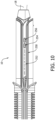
- Fig. 8 depicts a latch assembly 100 of hair styling apparatus 10.
- Latch assembly 100 may be mounted to at least one of arms 12, 14.
- latch assembly 100 is mounted to both upper arm 12 and lower arm 14.
- Latch assembly 100 may be connected to arms 12, 14 in proximity to the end where the power cord 18 extends from.
- latch assembly 100 includes a latch receiver 106, a latch mechanism 102, and a latch toggle 104.
- Latch mechanism 102 is configured to extend into and engage latch receiver 106.
- Latch receiver 106 may include features designed to interact with latch mechanism 102.
- Latch toggle 104 is directly or indirectly connected to latch mechanism 102 and is configured to position latch mechanism 102 between a locked position and an unlocked position.
- Latch toggle 104 may engage and/or disengage latch mechanism 102 from latch receiver 106, thereby facilitating opening and/or closing of upper arm 12 relative to lower arm 14.
- Latch toggle 104 may lock and/or unlock latch mechanism 102 relative to latch receiver 106, thereby locking and/or unlocking upper arm 12 relative to lower arm 14.
- Latch toggle 104 may lock arms 12, 14 in a closed position.
- Latch toggle 104 may override one or more switches 62, 64 such that if a switch is activated, latch toggle 104 can override that action to deactivate/activate a respective heating assembly.
- Latch toggle 104 may be a toggle switch, slide switch (see Fig. 9 ), push button, and combinations thereof.
- hair styling apparatus 10 may include a user interface that is configured to control heating element 56, 58. Specifically, heating element 56, 58 controls to heat inner heating plates 28, 42 and outer heating plates 29, 43.
- user interface 200 includes switch 202 and display 204.
- Switch 202 may turn heating elements 56, 58 "ON/OFF" as well as select which heating element 56, 58 is utilized. For example, switch 202 may select between activating outer heating plates 29, 43 inner heating plates 28, 42; or both outer heating plates 29, 43 and inner heating plates 28, 42. Switch 202 may also be capable of turning all heating plates 28, 29, 42, 43 "ON/OFF”.
- Display 204 may indicate which, if any, heating plate is activated.
- display 204 may illuminate both symbols, as referenced by "206". If only outer heating plate 29, 43 is activated, display 204 may illuminate only the outer symbol, as referenced by "208”. If only inner heating plate 28, 42 is activated, display 204 may illuminate only the inner symbol, as referenced by "210”. If no symbols are illuminated, heating plates 28, 29, 42, 43 may be OFF.
- hair styling apparatus 10 may include heating controls 250.
- Heating controls 250 may include indicator 252 and adjustment buttons 254, 256.
- Indicator 252 may depict heating plate temperature, which heating plate is active (e.g., inner heating plate, outer heating plate, both), and combinations thereof. The heating plate temperature may be adjusted by adjustment buttons 254, 256.
- Indicator 252 may depict the heating plate temperature by illuminating the temperature, lighting an area alongside the temperature (e.g., LED light), and/or by a mechanical indicator (e.g., flag, tab) that moves between the temperatures.
- Indicator 252 may depict a heating plate temperature range of about 100 degrees Fahrenheit to about 270 degrees Fahrenheit.
- Indicator 252 may depict a heating plate temperature range of about 150 degrees Fahrenheit to about 230 degrees Fahrenheit.
- Indicator 252 may depict which heating plate is active. Indicator 252 may depict which heating plate is active by illuminating the name (e.g., "barrel", “plates"), lighting an area alongside the name (e.g., LED light), and/or by a mechanical indicator (e.g., flag, tab) that moves between heating plate names.
- “Barrel” may refer to outer heating plates 29, 43 and “plates” may refer to inner heating plates 28, 42.
- the selection of the heating plates may be accomplished by mechanical selection (e.g., button, switch, toggle) to select inner heating plates 28, 42 or outer heating plates 29, 43. In other instances, the selection of the heating plates may be accomplished automatically.
- outer heating plates 29, 43 automatically activate when arms 12, 14 are moved to the closed position and heating plate covers 32, 46 slide towards the first ends of arms 12, 14 into the second position. Opening arms 12, 14 may automatically activate inner heating plates 28, 42. In some instances, heating plate covers 32, 46 do not have to cover outer heating plates 29, 43 to activate inner heating plates 28, 42 when arms 12, 14 are in an open position. Thus, a user can switch between open and closed positions without having to move heating plate covers 32, 46 towards tips 66, 68.
- hair styling apparatus 10 may be configured to deliver heat to hair positioned in proximity to (e.g., near, touching, partially touching) at least one arm 12, 14 for the desired styling operation. Hair styling apparatus 10 may be configured to deliver heat to hair positioned between arms 12, 14 for the desired styling operation.
- inner upper hair heating surface 30 and/or inner lower hair heating surface 44 may be a heating surface connected to a user interface (e.g., 200, 250).
- Hair styling apparatus 10 may be configured to deliver heat to hair positioned in proximity to an outside of arms 12, 14.
- outer upper hair heating surface 31 and/or outer lower hair heating surface 45 may be a heating surface connected to a user interface (e.g., 200, 250)
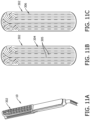
- Figs. 11A-11C depict hair styling apparatus 10 including a heating plate cover 302.
- Heating plate cover 302 includes ridges 304 and grooves 305 defined between ridges 304. Ridges 304 facilitate heat dissipation away from the heating plates.
- ridges 304 extend longitudinally along heating plate cover 302 and include curved portions at an end of heating plate cover 302.
- Fig. 11C illustrates openings 306 located in grooves 305 between ridges 304. Openings 306 are elongate and extend in the longitudinal direction. Openings 306 are uniformly spaced apart from each other with grooves 305.
- Heating plate cover 302 may be functionally similar, unless stated otherwise, to heating plate cover 32, 46. Heating plate cover 32, 46 may be substituted with heating plate cover 302, unless stated otherwise, without departing from the spirit/scope of this disclosure.
- Figs. 12A-12C depict hair styling apparatus 10 including a heating plate cover 402.
- Heating plate cover 402 includes ridges 404 and grooves 405 defined between ridges 404. Ridges 404 facilitate heat dissipation away from the heating plates.
- ridges 404 are linear and extend transversely across heating plate cover 402. Ridges 404 are parallel to each other and perpendicular to a longitudinal axis of heating plate cover 402.
- Fig. 12C illustrates openings 406 within grooves 405. Openings 406 are arranged in uniformly spaced rows within grooves 405 and between ridges 404.
- Heating plate cover 402 may be functionally similar, unless stated otherwise, to heating plate cover 32, 46. Heating plate cover 32, 46 may be substituted with heating plate cover 402, unless stated otherwise, without departing from the spirit/scope of this disclosure.
- Figs. 13A-13B depict a heating plate cover 502 for use with hair styling apparatus 10 (shown in Fig. 1 ).
- Heating plate cover 502 includes openings 504 and ridges 506. Ridges 506 may extend outward from a surface of heating plate cover 502 and along a transverse axis.
- the ridges 506 may include thinner sections 508 and thicker sections. Thinner sections 508 between openings 504 may reduce (or prevent) heat from spreading across heating plate cover 502. Ridges 506 may function as a heat sink to aid in cooling of heating plate cover 502.
- Heating plate cover 502 may be functionally similar, unless stated otherwise, to heating plate cover 32, 46. Heating plate cover 32, 46 may be substituted with heating plate cover 502, unless stated otherwise, without departing from the spirit/scope of this disclosure.
- FIGs. 14A-14B depict a heating plate cover 602 for use with hair styling apparatus 10 (shown in Fig. 1 ).
- Heating plate cover 602 includes diamond-shaped features 604 and vertical ridges 606.
- diamond-shaped features 604 are openings.
- Vertical ridges 606 may function as a heat sink to aid in cooling of heating plate cover 602.
- Thicker sections 608 of heating plate cover 602, defined between diamond-shaped features 604, may conduct heat central to the heating plate cover 602.
- Heating plate cover 602 may be functionally similar, unless stated otherwise, to heating plate cover 32, 46. Heating plate cover 32, 46 may be substituted with heating plate cover 602, unless stated otherwise, without departing from the spirit/scope of this disclosure.
- FIGs. 15A-15B depict heating plate cover 702 for use with hair styling apparatus 10 (shown in Fig. 1 ).
- Heating plate cover 702 may include horizontal features 704 and flared ends 706.
- Horizontal features 704 may facilitate airflow therethrough.
- Horizontal features 704 may also "shield" a user from engaging with the heating plates. Horizontal features 704 may aid in the cooling of heating plates through heating plate cover 702.
- horizontal features 704 are elongate openings. Flared ends 706 may include features 708 (e.g., raised features) for ease of grip (e.g., ribs).
- Heating plate cover 702 may include a flat surface 710 for displaying information or branding. Heating plate cover 702 may be functionally similar, unless stated otherwise, to heating plate cover 32, 46. Heating plate cover 32, 46 may be substituted with heating plate cover 702, unless stated otherwise, without departing from the spirit/scope of this disclosure.
- Figs. 16A-16B depict heating plate cover 802 for use with hair styling apparatus 10 (shown in Fig. 1 ).
- Heating plate cover 802 may include rib 804 and flared ends 806. Ribs 804 extend transversely across heating plate cover 802 and define openings therebetween to facilitate airflow therethrough. Ribs 804 may also "shield" a user from engaging with the heating plates. Ribs 804 may aid in the cooling of heating plates through heating plate cover 802. Flared ends 806 may provide a surface to assist with sliding heating plate cover 802 relative to arms 12/14.
- Heating plate cover 802 may include three columns of openings defined between ribs 804. Heating plate cover 802 may include flat feature 808 for displaying information or branding.
- Heating plate cover 802 may be functionally similar, unless stated otherwise, to heating plate cover 32, 46. Heating plate cover 32, 46 may be substituted with heating plate cover 802, unless stated otherwise, without departing from the spirit/scope of this disclosure.
- Figs. 17A-17B depict heating plate cover 902 for use with hair styling apparatus 10 (shown in Fig. 1 ).
- Heating plate cover 902 may include ribs 904 and flared ends 906. Ribs 904 extend transversely across heating plate cover 902 and define openings to facilitate airflow therethrough. Ribs 904 also "shield" a user from engaging with the heating plates. Ribs 904 may aid in the cooling of heating plates through heating plate cover 902. Flared ends 906 may include features 908 (e.g., raised features) for ease of grip (e.g., ribs).
- Heating plate cover 902 includes two columns of openings defined between ribs 904.
- Heating plate cover shield 902 may include flat feature 910 for displaying information or branding.
- Heating plate cover 902 may be functionally similar, unless stated otherwise, to heating plate cover 32, 46. Heating plate cover 32, 46 may be substituted with heating plate cover 902, unless stated otherwise, without departing from the spirit/scope of this disclosure.
- the features described herein may be horizontal (i.e., transverse), vertical (i.e., longitudinal) features, diagonal features, and the like (i.e., heat mitigation features).
- the heat mitigation features may aid in removing heat from the outer heating plate 29, 43 when the heating plate cover are positioned thereby.
- a user opens hair styling apparatus 10 and positions hair between arms 12, 14.
- the hair extends across and contacts inner hair heating surfaces 30, 44 of inner heating plates 28, 42.
- the user moves arms 12, 14 to the closed position and clamps hair between arms 12, 14.
- Heat may be delivered to the hair through at least one of inner hair heating surfaces 30, 44.
- a user can then move hair styling apparatus 10 along the hair to perform one or more styling operations such as straightening, curling, and combinations thereof.
- a user can comfortably and safely grab grips 20, 34 to perform a range of styling operations.
- Grips 20, 34 keep a user's fingers away from inner hair heating surfaces 30, 44 of inner heating plates 28, 42.
- a user may open hair styling apparatus 10 and remove the hair.
- a user may then position another section of hair between arms 12, 14 and clamp hair styling apparatus 10 onto the hair. This process may be repeated as desired.
- a user may close arms 12, 14 of hair styling apparatus 10 and positions hair relative to outer heating areas 26, 40.
- Heating plate covers 32, 46 may be covering outer hair heating surfaces 31, 45 of outer heating plates 29, 43. In some examples, heating plate covers 32, 46 may substantially cover outer hair heating surfaces 31, 45 of outer heating plates 29, 43 and tips 66, 68.
- a user slides heating plate covers 32, 46 towards the first ends of arms 12, 14 to expose at least a portion of outer hair heating surface 31, 45. In doing so, heating plate covers 32, 46 may engage with one or more switches (e.g., slot switch 62, arm switch 64) so as to activate heating element 56, 58, thereby heating outer hair heating surface 31, 45.
- switches e.g., slot switch 62, arm switch 64
- heating plate covers 32, 46 may define grips (not shown) for ease of control.
- the hair may extend around and/or in contact with one or more of outer hair heating surfaces 31, 45 of outer heating plates 29, 43.
- a user may, for example, curl their hair using heating plates 29, 43.
- Heating plate covers 32, 46 may lock arms 12, 14 in a closed position when heating plate covers 32, 46 are slid towards the first ends of arms 12, 14.
- upper heating plate cover 32 may slide within upper slot 48 and engage with slot switch 62.
- Lower heating plate cover 46 may slide within lower slot 50 and engage with slot switch 62.
- both upper and lower slot switches 62 may need to be activated to turn on outer heating plates 29, 43.
- upper heating plate cover 32 may slide within upper slot 48 and engage with slot switch 62 and lower heating plate cover 46 may slide within lower slot 50 and engage with slot switch 62 and either heating plate cover 32, 46 also engages with arm switch 64.
- engagement of the one or more switches 62, 64 by heating plate cover 32, 46 automatically switches usage between inner heating plate 28, 42 to outer heating plate 29, 43.
- Heating plate covers 32, 46 may lock arms 12, 14 in a closed position when heating plate covers 32, 46 are slid towards the first ends of arms 12, 14.
Landscapes
- Hair Curling (AREA)
- Shaping Of Tube Ends By Bending Or Straightening (AREA)
- Lining Or Joining Of Plastics Or The Like (AREA)
Applications Claiming Priority (1)
| Application Number | Priority Date | Filing Date | Title |
|---|---|---|---|
| US18/161,412 US20240251923A1 (en) | 2023-01-30 | 2023-01-30 | Combination hair styling apparatus with positionable heating plate covers |
Publications (2)
| Publication Number | Publication Date |
|---|---|
| EP4406450A2 true EP4406450A2 (de) | 2024-07-31 |
| EP4406450A3 EP4406450A3 (de) | 2024-11-13 |
Family
ID=88251655
Family Applications (1)
| Application Number | Title | Priority Date | Filing Date |
|---|---|---|---|
| EP24154436.0A Pending EP4406450A3 (de) | 2023-01-30 | 2024-01-29 | Kombinationshaarstylingvorrichtung mit positionierbaren heizplattenabdeckungen |
Country Status (6)
| Country | Link |
|---|---|
| US (1) | US20240251923A1 (de) |
| EP (1) | EP4406450A3 (de) |
| CN (2) | CN219813404U (de) |
| AU (1) | AU2024200252A1 (de) |
| CA (1) | CA3227027A1 (de) |
| GB (1) | GB2628700A (de) |
Families Citing this family (1)
| Publication number | Priority date | Publication date | Assignee | Title |
|---|---|---|---|---|
| US20240251923A1 (en) * | 2023-01-30 | 2024-08-01 | Spectrum Brands, Inc. | Combination hair styling apparatus with positionable heating plate covers |
Family Cites Families (14)
| Publication number | Priority date | Publication date | Assignee | Title |
|---|---|---|---|---|
| KR200246302Y1 (ko) * | 2001-04-30 | 2001-10-12 | 정재욱 | 미용용 고데기 |
| KR100905499B1 (ko) * | 2004-01-19 | 2009-07-01 | 이대범 | 스트레이트퍼머용 헤어아이론 |
| KR200358502Y1 (ko) * | 2004-04-09 | 2004-08-11 | 최영만 | 휴대용 전기 머리 인두 |
| KR200398545Y1 (ko) * | 2005-08-04 | 2005-10-12 | 노태형 | 헤어 아이론 |
| KR101145679B1 (ko) * | 2009-07-14 | 2012-05-29 | 이대범 | 젖은모발퍼머시술이 가능한 헤어아이론 |
| US8132573B1 (en) * | 2010-01-13 | 2012-03-13 | Barbara Jones | Curling iron with retractable heat shield |
| GB2505171A (en) * | 2012-08-20 | 2014-02-26 | Jemella Ltd | A hair styling apparatus with a resiliently flexible portion |
| CN203676383U (zh) * | 2014-01-10 | 2014-07-02 | 温州市拉博电器有限公司 | 一种多功能烫发器 |
| WO2015161134A1 (en) * | 2014-04-16 | 2015-10-22 | Spectrum Brands, Inc. | Heated appliance |
| CN106073106A (zh) * | 2016-06-02 | 2016-11-09 | 温州市顺怡科技有限公司 | 一种烫发器 |
| CN210726976U (zh) * | 2019-10-21 | 2020-06-12 | 张义 | 直卷发器 |
| CN211323410U (zh) * | 2019-12-10 | 2020-08-25 | 华煌电业制品(龙川)有限公司 | 一种旋钮式可调温度直卷发器 |
| FR3134693B1 (fr) * | 2022-04-21 | 2024-04-12 | Oreal | Dispositif de traitement de la chevelure |
| US20240251923A1 (en) * | 2023-01-30 | 2024-08-01 | Spectrum Brands, Inc. | Combination hair styling apparatus with positionable heating plate covers |
-
2023
- 2023-01-30 US US18/161,412 patent/US20240251923A1/en active Pending
- 2023-02-07 CN CN202320357224.2U patent/CN219813404U/zh active Active
-
2024
- 2024-01-15 AU AU2024200252A patent/AU2024200252A1/en active Pending
- 2024-01-24 CA CA3227027A patent/CA3227027A1/en active Pending
- 2024-01-29 GB GB2401120.7A patent/GB2628700A/en active Pending
- 2024-01-29 EP EP24154436.0A patent/EP4406450A3/de active Pending
- 2024-01-30 CN CN202410126113.XA patent/CN118402673A/zh active Pending
Also Published As
| Publication number | Publication date |
|---|---|
| CN219813404U (zh) | 2023-10-13 |
| AU2024200252A1 (en) | 2024-08-15 |
| GB202401120D0 (en) | 2024-03-13 |
| EP4406450A3 (de) | 2024-11-13 |
| CN118402673A (zh) | 2024-07-30 |
| CA3227027A1 (en) | 2025-04-09 |
| GB2628700A (en) | 2024-10-02 |
| US20240251923A1 (en) | 2024-08-01 |
Similar Documents
| Publication | Publication Date | Title |
|---|---|---|
| EP4406450A2 (de) | Kombinationshaarstylingvorrichtung mit positionierbaren heizplattenabdeckungen | |
| CN102711549B (zh) | 头发造型装置和方法 | |
| CN207168088U (zh) | 手持器具 | |
| US20180042352A1 (en) | Hair styling apparatus having dual switch and lock actuator | |
| US20130263881A1 (en) | Hair straightener | |
| US20050224091A1 (en) | Ion curling iron and straightener | |
| WO2006044570A2 (en) | Split-barrel locking mechanism for hair appliance | |
| US8857447B2 (en) | Hair treatment apparatus with cover for control elements | |
| JP2019079821A (ja) | 手持ち式電気器具 | |
| CN207492284U (zh) | 卷发器 | |
| CN201422539Y (zh) | 电发夹 | |
| JP7364155B2 (ja) | ヘアスタイリング装置 | |
| KR101842932B1 (ko) | 다용도 헤어 미용 기구 | |
| KR102837237B1 (ko) | 후면발열 그랩형 모발고데기 | |
| DE102004036203A1 (de) | Handluftdusche | |
| JP2012085922A (ja) | ヘアーアイロン装置 | |
| KR102837226B1 (ko) | 두피보호형 모발고데기 | |
| KR102837232B1 (ko) | 측면발열 그랩형 모발고데기 | |
| JP2008543392A (ja) | ヘアスタイリング装置 | |
| EP1874150B1 (de) | Haarformgerät | |
| AU2011202604A1 (en) | Ion curling iron and straightener | |
| HK1169287A (en) | A hair styling apparatus and method |
Legal Events
| Date | Code | Title | Description |
|---|---|---|---|
| PUAI | Public reference made under article 153(3) epc to a published international application that has entered the european phase |
Free format text: ORIGINAL CODE: 0009012 |
|
| STAA | Information on the status of an ep patent application or granted ep patent |
Free format text: STATUS: THE APPLICATION HAS BEEN PUBLISHED |
|
| AK | Designated contracting states |
Kind code of ref document: A2 Designated state(s): AL AT BE BG CH CY CZ DE DK EE ES FI FR GB GR HR HU IE IS IT LI LT LU LV MC ME MK MT NL NO PL PT RO RS SE SI SK SM TR |
|
| PUAL | Search report despatched |
Free format text: ORIGINAL CODE: 0009013 |
|
| AK | Designated contracting states |
Kind code of ref document: A3 Designated state(s): AL AT BE BG CH CY CZ DE DK EE ES FI FR GB GR HR HU IE IS IT LI LT LU LV MC ME MK MT NL NO PL PT RO RS SE SI SK SM TR |
|
| RIC1 | Information provided on ipc code assigned before grant |
Ipc: A45D 2/00 20060101ALN20241008BHEP Ipc: A45D 1/06 20060101ALN20241008BHEP Ipc: A45D 1/00 20060101ALN20241008BHEP Ipc: A45D 1/04 20060101AFI20241008BHEP |
|
| STAA | Information on the status of an ep patent application or granted ep patent |
Free format text: STATUS: REQUEST FOR EXAMINATION WAS MADE |
|
| 17P | Request for examination filed |
Effective date: 20250513 |