EP4406108B1 - Motor control system for determining an operating point for controlling an electric motor - Google Patents
Motor control system for determining an operating point for controlling an electric motor Download PDFInfo
- Publication number
- EP4406108B1 EP4406108B1 EP21782916.7A EP21782916A EP4406108B1 EP 4406108 B1 EP4406108 B1 EP 4406108B1 EP 21782916 A EP21782916 A EP 21782916A EP 4406108 B1 EP4406108 B1 EP 4406108B1
- Authority
- EP
- European Patent Office
- Prior art keywords
- motor
- control system
- operating point
- electronic
- speed
- Prior art date
- Legal status (The legal status is an assumption and is not a legal conclusion. Google has not performed a legal analysis and makes no representation as to the accuracy of the status listed.)
- Active
Links
Images





Classifications
-
- H—ELECTRICITY
- H02—GENERATION; CONVERSION OR DISTRIBUTION OF ELECTRIC POWER
- H02P—CONTROL OR REGULATION OF ELECTRIC MOTORS, ELECTRIC GENERATORS OR DYNAMO-ELECTRIC CONVERTERS; CONTROLLING TRANSFORMERS, REACTORS OR CHOKE COILS
- H02P21/00—Arrangements or methods for the control of electric machines by vector control, e.g. by control of field orientation
- H02P21/22—Current control, e.g. using a current control loop
-
- H—ELECTRICITY
- H02—GENERATION; CONVERSION OR DISTRIBUTION OF ELECTRIC POWER
- H02P—CONTROL OR REGULATION OF ELECTRIC MOTORS, ELECTRIC GENERATORS OR DYNAMO-ELECTRIC CONVERTERS; CONTROLLING TRANSFORMERS, REACTORS OR CHOKE COILS
- H02P23/00—Arrangements or methods for the control of AC motors characterised by a control method other than vector control
- H02P23/14—Estimation or adaptation of motor parameters, e.g. rotor time constant, flux, speed, current or voltage
-
- B—PERFORMING OPERATIONS; TRANSPORTING
- B62—LAND VEHICLES FOR TRAVELLING OTHERWISE THAN ON RAILS
- B62D—MOTOR VEHICLES; TRAILERS
- B62D5/00—Power-assisted or power-driven steering
- B62D5/04—Power-assisted or power-driven steering electrical, e.g. using an electric servo-motor connected to, or forming part of, the steering gear
- B62D5/0457—Power-assisted or power-driven steering electrical, e.g. using an electric servo-motor connected to, or forming part of, the steering gear characterised by control features of the drive means as such
- B62D5/0481—Power-assisted or power-driven steering electrical, e.g. using an electric servo-motor connected to, or forming part of, the steering gear characterised by control features of the drive means as such monitoring the steering system, e.g. failures
-
- H—ELECTRICITY
- H02—GENERATION; CONVERSION OR DISTRIBUTION OF ELECTRIC POWER
- H02J—ELECTRIC POWER NETWORKS; CIRCUIT ARRANGEMENTS OR SYSTEMS FOR SUPPLYING OR DISTRIBUTING ELECTRIC POWER; SYSTEMS FOR STORING ELECTRIC ENERGY
- H02J7/00—Circuit arrangements for charging or discharging batteries or for supplying loads from batteries
- H02J7/855—Circuit arrangements for charging or discharging batteries or for supplying loads from batteries with circuits adapted for supplying loads from the battery
-
- H—ELECTRICITY
- H02—GENERATION; CONVERSION OR DISTRIBUTION OF ELECTRIC POWER
- H02P—CONTROL OR REGULATION OF ELECTRIC MOTORS, ELECTRIC GENERATORS OR DYNAMO-ELECTRIC CONVERTERS; CONTROLLING TRANSFORMERS, REACTORS OR CHOKE COILS
- H02P21/00—Arrangements or methods for the control of electric machines by vector control, e.g. by control of field orientation
- H02P21/14—Estimation or adaptation of machine parameters, e.g. flux, current or voltage
-
- H—ELECTRICITY
- H02—GENERATION; CONVERSION OR DISTRIBUTION OF ELECTRIC POWER
- H02P—CONTROL OR REGULATION OF ELECTRIC MOTORS, ELECTRIC GENERATORS OR DYNAMO-ELECTRIC CONVERTERS; CONTROLLING TRANSFORMERS, REACTORS OR CHOKE COILS
- H02P25/00—Arrangements or methods for the control of AC motors characterised by the kind of AC motor or by structural details
- H02P25/02—Arrangements or methods for the control of AC motors characterised by the kind of AC motor or by structural details characterised by the kind of motor
- H02P25/022—Synchronous motors
- H02P25/03—Synchronous motors with brushless excitation
-
- B—PERFORMING OPERATIONS; TRANSPORTING
- B62—LAND VEHICLES FOR TRAVELLING OTHERWISE THAN ON RAILS
- B62D—MOTOR VEHICLES; TRAILERS
- B62D5/00—Power-assisted or power-driven steering
- B62D5/04—Power-assisted or power-driven steering electrical, e.g. using an electric servo-motor connected to, or forming part of, the steering gear
- B62D5/0457—Power-assisted or power-driven steering electrical, e.g. using an electric servo-motor connected to, or forming part of, the steering gear characterised by control features of the drive means as such
- B62D5/046—Controlling the motor
-
- B—PERFORMING OPERATIONS; TRANSPORTING
- B62—LAND VEHICLES FOR TRAVELLING OTHERWISE THAN ON RAILS
- B62D—MOTOR VEHICLES; TRAILERS
- B62D5/00—Power-assisted or power-driven steering
- B62D5/04—Power-assisted or power-driven steering electrical, e.g. using an electric servo-motor connected to, or forming part of, the steering gear
- B62D5/0457—Power-assisted or power-driven steering electrical, e.g. using an electric servo-motor connected to, or forming part of, the steering gear characterised by control features of the drive means as such
- B62D5/0481—Power-assisted or power-driven steering electrical, e.g. using an electric servo-motor connected to, or forming part of, the steering gear characterised by control features of the drive means as such monitoring the steering system, e.g. failures
- B62D5/0484—Power-assisted or power-driven steering electrical, e.g. using an electric servo-motor connected to, or forming part of, the steering gear characterised by control features of the drive means as such monitoring the steering system, e.g. failures for reaction to failures, e.g. limp home
-
- H—ELECTRICITY
- H02—GENERATION; CONVERSION OR DISTRIBUTION OF ELECTRIC POWER
- H02P—CONTROL OR REGULATION OF ELECTRIC MOTORS, ELECTRIC GENERATORS OR DYNAMO-ELECTRIC CONVERTERS; CONTROLLING TRANSFORMERS, REACTORS OR CHOKE COILS
- H02P2101/00—Special adaptation of control arrangements for generators
- H02P2101/45—Special adaptation of control arrangements for generators for motor vehicles, e.g. car alternators
Definitions
- the invention relates to a motor control system for determining an operating point for controlling an electric motor, a control system having the motor control system, an electronic system having the control system, a vehicle having the electronic system, a method for determining an operating point for controlling an electric motor, a computer program and a computer-readable data carrier.
- the motor control system further comprises an operating point controller having an input for receiving a fixed battery voltage reference, the modified speed and the requested torque, the operating point controller being configured for determining the operating point for controlling the electric motor based on the received fixed battery voltage reference, the modified speed and the requested torque.
- the invention now proposes to include a calibrator in a motor control system to change the operating point controller's inputs.
- the calibrator just as the operating point controller, may be understood as modules of the motor control system, which may be implemented as computer codes, in particular algorithms, to be executed on a computer and/or as electric circuits executing their function.
- the equations of the operating point controller are simplified but the calibrator will variate the inputs to oblige the operating point controller to provide the most efficient operating points.
- a modification of the raw equations by means of performing variables with constants and (more or less) complex functions allows to decompose the different calculations to make the whole process faster to compute.
- the motor control system allows more flexibility, which could permit to choose a balance between different CPU constraints and motor control performances. All operating points can be optimized without having to upgrade the CPU.
- the motor control system further comprises a control loop configured for receiving the determined operating point, comparing the determined operating point to a measured current and output a voltage request.
- the electric motor is a brushless alternating current motor.
- the power stage control system is configured to transform a voltage request received from the motor control system into duty cycles to command switches of a power stage of the electronic control unit.
- the above object is solved by means of an electronic system comprising a mechanical system and an electric system, the electric system having the control system according to the second aspect of the invention.
- the electronic system is an electronic vehicle system.
- the electronic system may be from an automotive application.
- the electronic system is an electronic power steering system.
- other applications in vehicles such as vehicle electric traction systems, can be implemented as well.
- the above object is solved by means of a vehicle comprising the electronic system according to the third aspect of the invention.
- the method further comprises the steps of comparing the determined operating point to a measured current and outputting a voltage request.
- Fig. 1 depicts an electronic (vehicle) system 1 in the form of an electronic power steering (EPS) system 1 for a vehicle 15 (see Fig. 2 ).
- the electronic power steering system 1 comprises a mechanical system 14 and an electric system 13.
- the mechanical system 14 includes a torque sensor 7, a steering wheel 8, a column 9, a pinion 10, a rack 11 and wheels 12.
- the electric system 13 includes an electric motor 4, which in this case is a brushless alternating current motor (BLAC motor), a battery 2, an electronic control unit (ECU) 3 and at least one sensor, such as the depicted motor position sensor 6, thereby forming the so-called powerpack 13.
- a gearbox 5 of the EPS system 1 makes the junction between both systems 13, 14.
- the motor 4 operates in the so-called "normal operating mode".
- the power depicted as second curve 21 increases linearly, up to a certain speed. From this certain speed in the right area 23, the motor 4 operates in the so-called “flux weakening operating mode", which permits to control the motor 4 in higher speed, for the same power (against losing torque availability).
- a third objective of the motor control is to keep as much assistance availability as possible (i.e., not limit the assistance too much). OEMs expect to have certain amount of assistance in certain circumstances which requires the motor control to be able to provide as much torque as the motor 4 can do, otherwise it will result in overdesigning the powerpack 13 to be able to comply with the OEM torque-vs-speed requirements.
- the first objective of the motor control is to apply the right voltage across the motor phases (for the right torque) while avoiding to have phase-to-phase voltage greater than the battery voltage.
- the voltage induced by the rotation of the motor (so-called "Back-EMF”; referred to as E in Fig. 5 ) increases linearly with the motor speed, which makes the phase-to-phase voltage increase.
- the motor control has the role to induce a phase-shift between the phase current and the phase back-EMF when required (in high speed).
- the electrical components may be represented in a Park plan, which may be obtained after a Clarke and Park transformation.
- These are constant and rotor angle dependent matrices that are multiplied by the three phase components. They are generally known in the art and to the person skilled in the art.
- the Park plan permits to represent the three phases sinusoidal current into two constant components I q and I d .
- the transition from three-phase (temporal) plan to a Clarke/Park plan permits to represent parameters from stator to rotor point of view.
- the component I q can be associated with how much torque T is provided and the component I d with how much phase-shift is induced.
- the motor 4 can operate anywhere in the area of the graph of Fig. 9 . But if the motor 4 operates outside of it, the current will be higher than what the hardware has been designed for, and this might risk reducing the life of the ECU 3, cause the ECU 3 to dysfunction or even endanger the driver.
- the motor control would fulfill its third and fourth objective, which are to be able to provide as much assistance as possible when needed and be as efficient as possible in terms of current consumption for the same result/assistance.
- Batteries 2 are never charged at the same level throughout the life of the vehicle 15. Sometimes, the headlamps are on, as well as the radio and other electrical modules which reduce the battery voltage. Other times, the battery 2 is completely charged and the motor 4 together with the alternator recharge the battery 2 which makes its voltage very high. The weather also affects the temperature of the battery 2, which also affects its voltage. All of this has to be considered.
- Fig. 13 gives a closer look to the effect of the battery voltage on the operating area of the motor control (for the same speed, here at medium speed). It can be seen that the operating area shrinks when the battery voltage decreases, which gives completely new optimal operating points.
- a calibrator 45 is added upstream of the OPC 43 to adjust its input speed in function of the real motor control inputs, so that it will shift the operating points when the battery voltage is higher or lower than the reference one.
Landscapes
- Engineering & Computer Science (AREA)
- Power Engineering (AREA)
- Chemical & Material Sciences (AREA)
- Combustion & Propulsion (AREA)
- Transportation (AREA)
- Mechanical Engineering (AREA)
- Control Of Ac Motors In General (AREA)
Description
- The invention relates to a motor control system for determining an operating point for controlling an electric motor, a control system having the motor control system, an electronic system having the control system, a vehicle having the electronic system, a method for determining an operating point for controlling an electric motor, a computer program and a computer-readable data carrier.
-
US 2006/055363 A1 discloses a motor system comprising d-axis and q-axis look-up tables for providing d-axis and q-axis command currents for any given speed, desired torque and DC link bus voltage. - It is an object of the invention to provide a way by means of which the most optimal operating points for an electric motor operating at different speeds, torques, voltages, temperatures, etc. may be determined while still satisfying CPU load (calculation time) and memory (size of variables) constraints.
- This object is solved by the subject-matter of the claims. In particular, this object is solved by a motor control system according to claim 1, a control system according to
claim 5, an electronic system according toclaim 7, a vehicle according toclaim 10, a method according toclaim 11, a computer program according toclaim 14 and a computer-readable data carrier according toclaim 15. Further details of the invention unfold from the other claims as well as the description and the drawings. Thereby, the features and details described in connection with the motor control system of the invention apply in connection with the control system of the invention, the electronic system of the invention, the vehicle of the invention, the method of the invention, the computer program of the invention and the computer-readable data carrier of the invention, so that regarding the disclosure of the individual aspects of the invention it is or can be referred to one another. - According to a first aspect of the invention, the above object is solved by means of a motor control system for determining an operating point for controlling an electric motor in an electric system comprising a battery and an electronic control unit.
- The motor control system comprises a calibrator having an input for receiving a battery voltage of the battery and a motor (or rotor) speed and a requested torque of the electric motor, the calibrator being configured to calculate a modified speed based on the received battery voltage, motor speed and the requested torque.
- The motor control system further comprises an operating point controller having an input for receiving a fixed battery voltage reference, the modified speed and the requested torque, the operating point controller being configured for determining the operating point for controlling the electric motor based on the received fixed battery voltage reference, the modified speed and the requested torque.
- The identified disadvantage in the prior art is that equations are simplified in a way that all operating points are not optimum. However, using raw equations requires a computer's processor which is not reasonable for many applications, in particular automotive applications.
- The invention now proposes to include a calibrator in a motor control system to change the operating point controller's inputs. The calibrator, just as the operating point controller, may be understood as modules of the motor control system, which may be implemented as computer codes, in particular algorithms, to be executed on a computer and/or as electric circuits executing their function.
- The equations of the operating point controller are simplified but the calibrator will variate the inputs to oblige the operating point controller to provide the most efficient operating points. A modification of the raw equations by means of performing variables with constants and (more or less) complex functions allows to decompose the different calculations to make the whole process faster to compute.
- Despite requiring (reasonable) additional CPU load (few micro-seconds) and memory (few kilo-bytes), the motor control system allows more flexibility, which could permit to choose a balance between different CPU constraints and motor control performances. All operating points can be optimized without having to upgrade the CPU.
- In particular, the operating point is defined by a current to be applied through each of the phases of the electric motor.
- Moreover, in particular, the motor control system further comprises a control loop configured for receiving the determined operating point, comparing the determined operating point to a measured current and output a voltage request.
- Further, in particular, the electric motor is a brushless alternating current motor.
- According to a second aspect of the invention, the above object is solved by means of a control system comprising the motor control system according to the first aspect of the invention, whereby the control system further comprises a power stage control system connected to the motor control system.
- In particular, the power stage control system is configured to transform a voltage request received from the motor control system into duty cycles to command switches of a power stage of the electronic control unit.
- According to a third aspect of the invention, the above object is solved by means of an electronic system comprising a mechanical system and an electric system, the electric system having the control system according to the second aspect of the invention.
- In particular, the electronic system is an electronic vehicle system. In other words, the electronic system may be from an automotive application.
- Moreover, in particular, the electronic system is an electronic power steering system. However, other applications in vehicles, such as vehicle electric traction systems, can be implemented as well.
- According to a fourth aspect of the invention, the above object is solved by means of a vehicle comprising the electronic system according to the third aspect of the invention.
- According to a fifth aspect of the invention, the above object is solved by means of a method for determining an operating point for controlling an electric motor in an electric system comprising a battery and an electronic control unit, the method comprising the steps of:
- receiving a battery voltage of the battery, a motor speed and a requested torque of the electric motor,
- calculating a modified speed based on the received battery voltage, motor speed and requested torque,
- receiving a fixed battery voltage reference, the modified speed and a requested torque, and
- determining the operating point for controlling the electric motor based on the received fixed battery voltage reference, the modified speed and the requested torque.
- In particular, the method further comprises the steps of comparing the determined operating point to a measured current and outputting a voltage request.
- Moreover, in particular, the method further comprises the steps of transforming a voltage request into duty cycles and correspondingly commanding switches of a power stage of the electronic control unit.
- According to a sixth aspect of the invention, the above object is solved by means of a computer program comprising instructions which, when the program is executed by a computer, cause the computer to carry out the method according to the fifth aspect of the invention.
- According to a seventh aspect of the invention, the above object is solved by means of a computer-readable data carrier having stored thereon the computer program according to the sixth aspect of the invention.
- Further advantages, features and details of the invention unfold from the following description, in which by reference to drawings
Figs. 1 - 16 , embodiments of the present invention are described in detail. Thereby, the features from the claims as well as the features mentioned in the description can be essential for the invention as taken alone or in an arbitrary combination. In the drawings, there is schematically shown: - Fig. 1
- an electronic power steering system;
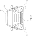
- Fig. 2
- a vehicle having the electronic power steering system of
Fig. 1 ; - Fig. 3
- a torque-speed-graph for the electronic power steering system of
Fig. 1 ; - Fig. 4
- a further torque-speed-graph similar to
Fig. 3 ; - Fig. 5
- an electric system of the electronic power steering system of
Fig. 1 ; - Fig. 6
- a power stage of the ECU of the electronic power steering system of
Fig. 1 ; - Fig. 7
- a control system of the electronic power steering system of
Fig. 1 ; - Fig. 8
- a graph corresponding to the motor control system in the control system of
Fig. 7 ; - Fig. 9
- a further graph similar to
Fig. 8 ; - Fig. 10
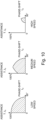
- graphs of operating areas for different speeds;
- Fig. 11
- graphs of operating areas for different current consumptions;
- Fig. 12
- the graphs of
Fig. 10 with optimal operating points included; - Fig. 13
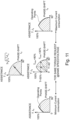
- graphs of operating areas with optimal operating points included and for different charge levels of the battery;
- Fig. 14
- a motor control system for the control system of
Fig. 7 ; - Fig. 15
- a further motor control system for the control system of
Fig. 7 ; and - Fig. 16
- further graphs of operating areas for different charge levels of the battery.
- Throughout
Figs. 1 - 16 , alike elements are referred to with the same reference number. -
Fig. 1 depicts an electronic (vehicle) system 1 in the form of an electronic power steering (EPS) system 1 for a vehicle 15 (seeFig. 2 ). The electronic power steering system 1 comprises amechanical system 14 and anelectric system 13. Themechanical system 14 includes atorque sensor 7, asteering wheel 8, acolumn 9, apinion 10, arack 11 andwheels 12. Theelectric system 13 includes anelectric motor 4, which in this case is a brushless alternating current motor (BLAC motor), abattery 2, an electronic control unit (ECU) 3 and at least one sensor, such as the depictedmotor position sensor 6, thereby forming the so-calledpowerpack 13. Agearbox 5 of the EPS system 1 makes the junction between bothsystems - When the
steering wheel 8 is rotated, the requested torque is measured by thetorque sensor 7, and thepowerpack 13 accordingly provides torque in the same direction which helps the driver to steer the vehicle 15 (schematically depicted inFig. 2 withsystems - The torque provided by the
powerpack 13 is multiplied by thegearbox 5 and is applied on thecolumn 9 or therack 11 according to the type of vehicle (truck or small city car). The speed of the steering wheel 8 (imposed by the driver) is multiplied by thegearbox 5 on the powerpack'smotor 4. Therefore,EPS motors 4 are used in a big range of speed and of torque as well. -
Fig. 3 depicts the typical shape of thefirst curve 20 representing how much torque (assistance) is available depending on the speed of thesteering wheel 8. - Most of the time, the
steering wheel 8 is rotated quite slowly which makes the EPS system 1 operate mostly in theleft area 22 ofFig. 4 including thefirst curve 20. However, during quick maneuvers or during abnormal driving circumstances (such as hitting the side road), the EPS system 1 operates in theright area 23 of thefirst curve 20. For safety reasons, the EPS system 1 must be able to operate in the motor's complete operating range. For car emission efficiency, themotor 4 must be controlled in the most efficient way, no matter the operating area (even though the EPS system 1 might not be used in the high-speed area that often). Also, the hardware (electric) part of theECU 3 is designed on the assumption that the EPS system 1 is controlled perfectly (another reason to control themotor 4 as well as possible). - In the
left area 22 ofFig. 4 , themotor 4 operates in the so-called "normal operating mode". The power depicted assecond curve 21 increases linearly, up to a certain speed. From this certain speed in theright area 23, themotor 4 operates in the so-called "flux weakening operating mode", which permits to control themotor 4 in higher speed, for the same power (against losing torque availability). - In
Fig. 5 , thepower stage 30, in this case a 3-phase-inverter, of theECU 3 having sixswitches 31 is shown in more detail. Thepower stage 30 allows to shape the DC voltage from thebattery 2 into AC sine shapes to apply on each phase of themotor 4. Each phase of themotor 4 can be represented as a RL circuit in series with a voltage source E. This voltage source E has a sine shape at constant motor speed, and its amplitude increases with the motor speed. - A first objective of the motor control is to apply the right voltage across each phase of the
motor 4, making sure the phase-to-phase voltage of themotor 4 does not exceed the voltage of thebattery 2. Otherwise, the EPS system 1 would not operate in motor mode but rather in generator mode, which would brake themotor 4 and violate safety goals. - Since the hardware designers consider perfect motor control and certain current during certain amount of time in order to choose the right components and thermal dissipation parameters, it is required to not exceed the maximum current allowed in each phase, which is the second objective.
- A third objective of the motor control is to keep as much assistance availability as possible (i.e., not limit the assistance too much). OEMs expect to have certain amount of assistance in certain circumstances which requires the motor control to be able to provide as much torque as the
motor 4 can do, otherwise it will result in overdesigning thepowerpack 13 to be able to comply with the OEM torque-vs-speed requirements. - A fourth objective is to make the control as efficient as possible (i.e., less current for same power provided).
- Basically, the motor control is responsible to control the
motor 4 in the most efficient way while adapting to its environment (battery voltage, hardware maximum current), but also to follow the driver assistance expectations and avoid making thevehicle 15 consume more fuel to recharge thebattery 2 because of the EPS system 1 excess current consumption. - As explained earlier, the first objective of the motor control is to apply the right voltage across the motor phases (for the right torque) while avoiding to have phase-to-phase voltage greater than the battery voltage. However, the voltage induced by the rotation of the motor (so-called "Back-EMF"; referred to as E in
Fig. 5 ) increases linearly with the motor speed, which makes the phase-to-phase voltage increase. - Therefore, as shown in
Fig. 6 , to avoid an overvoltage, the motor control has the role to induce a phase-shift between the phase current and the phase back-EMF when required (in high speed). - In
Fig. 7 , thecontrol system 40 for thepowerpack 13 is depicted in a simplified way. It may be seen that for a certain torque request and a certain motor speed, amotor control system 41 of thecontrol system 40 will provide voltage (Vd, Vq) request to have more or less current (for torque T) with more or less phase-shift ϕ (for phase-to-phase limitation). Then the powerstage control system 42 of thecontrol system 40 transforms the voltage request into duty cycles to command the sixswitches 31 correctly. - Now, as shown in
Fig. 8 , themotor control system 41 can be represented as a graph with two axes: how much assistance (Y-axis) can be provided in function of the phase-shift (X-axis) induced between the current and the Back-EMF. The assistance is equivalent to how much torque the motor provides [0 : 100 %]. The phase-shift ϕ will never exceed 90 degrees. - To control the
motor 4 in a simpler way (less CPU load and better system understanding), the electrical components (voltage, current, phases resistance and inductance) may be represented in a Park plan, which may be obtained after a Clarke and Park transformation. These are constant and rotor angle dependent matrices that are multiplied by the three phase components. They are generally known in the art and to the person skilled in the art. The Park plan permits to represent the three phases sinusoidal current into two constant components Iq and Id. The transition from three-phase (temporal) plan to a Clarke/Park plan permits to represent parameters from stator to rotor point of view. - Using the representation of
Fig. 8 of thesystem 40 showing assistance vs phase-shift as explained before, the component Iq can be associated with how much torque T is provided and the component Id with how much phase-shift is induced. - Coming back to the initial issue of handling the phase-to-phase voltage equal or lower than the battery voltage, there also comes the necessity to limit the current flow to what has been expected by the hardware design. The current that flows through each phase of the
motor 4 has an amplitude | I | that is equal to the root square of Id 2 + Iq 2, as shown inFig. 9 . This is the reason why when applying some phase-shift, the maximum torque/assistance that can be provided is reduced (with this quarter circle shape). - The
motor 4 can operate anywhere in the area of the graph ofFig. 9 . But if themotor 4 operates outside of it, the current will be higher than what the hardware has been designed for, and this might risk reducing the life of theECU 3, cause theECU 3 to dysfunction or even endanger the driver. - Therefore, operating in this area fulfills the second criteria of the motor control's objectives, which is the hardware limitation.
- Once again, when increasing the motor speed ωe, the Back-EMF's "E" amplitude increases, which increases the phase voltage, which increases the phase-to-phase voltage. Now, increasing the current to Back-EMF phase-shift reduces the phase voltage which reduces the phase-to-phase voltage. By combining both effects, a proper motor control can be created.
- Looking at the operating area, depending on the motor speed ωe as depicted in
Fig. 10 , it can be seen that the operating area shrinks when themotor 4 runs faster. That is explained by the fact that when the speed is so high that the phase-to-phase voltage is greater than the battery voltage, there is no choice but to apply a phase-shift to avoid going in generator mode (phase-to-phase voltage greater than battery voltage). - Now, from a strategic point of view, it would be possible to provide 80 % of the assistance by applying 40 ° of phase-shift when the driver needs the most assistance, and to increase the phase-shift along with reducing the torque T applied when the driver does not need much assistance. This is depicted on the right graph of
Fig. 11 and would make the motor operate 100 % of the time at maximum current consumption, which would be the least efficient option in terms of motor control. - However, if we were closer to the operation according to the graph on the left of
Fig. 12 and provide the point where I = sqrt(Id 2 + Iq 2) is the minimum, that would be the most efficient way to control themotor 4. - Therefore, by not only operating in the area of the graphs of
Fig. 10 for the different speeds, but by operating on the thick lines added toFig. 10 and represented inFig. 12 , which is the limit where the phase-to-phase peak voltage is equal to the battery voltage, the motor control would fulfill its third and fourth objective, which are to be able to provide as much assistance as possible when needed and be as efficient as possible in terms of current consumption for the same result/assistance. - Now, adding a last difficulty in the motor control:
Batteries 2 are never charged at the same level throughout the life of thevehicle 15. Sometimes, the headlamps are on, as well as the radio and other electrical modules which reduce the battery voltage. Other times, thebattery 2 is completely charged and themotor 4 together with the alternator recharge thebattery 2 which makes its voltage very high. The weather also affects the temperature of thebattery 2, which also affects its voltage. All of this has to be considered. -
Fig. 13 gives a closer look to the effect of the battery voltage on the operating area of the motor control (for the same speed, here at medium speed). It can be seen that the operating area shrinks when the battery voltage decreases, which gives completely new optimal operating points. -
Fig. 14 now gives a detailed schematic illustration of amotor control system 41, which may be used in thecontrol system 40 ofFig. 7 . It can be seen that the operating point controller (OPC) 43 in fact depends on three inputs: the torque T request (for the assistance), the rotor speed ωe and the battery voltage measured (for the right phase-shift). TheOPC 43 provides requests of current ID, IQ to be applied through each phase, and a regulator/control loop 44 will compare it to the measured current and give voltage requests in the output (for thepower stage control 42, seeFig. 7 ). - Focusing on the
OPC 43, the equations for "perfect" motor control require four dimensional/parameters (current, voltage, speed, torque) equations. Now taking into consideration the automotive industry application, the central processing unit (CPU) of theECU 3, which contains all the numeric motor systems, does not have much memory and does not have a very high operating frequency (much less than a computer processor). Therefore, it is required to simplify algorithms and to find balance between memory and CPU load. - According to the invention, the
OPC 43 is now designed for only one reference battery voltage (e.g., 13 V since it is the typical battery voltage when it is charged) to make the OPC 43 a 3-dimensional equations algorithm instead of a 4-dimensional one. - In addition to that, a
calibrator 45 is added upstream of theOPC 43 to adjust its input speed in function of the real motor control inputs, so that it will shift the operating points when the battery voltage is higher or lower than the reference one. - To have an example, it is referred to
Fig. 16 . It is assumed that speed is constant (in the medium range in the example ofFig. 16 ). The operating area for several battery voltages is represented. It can be seen that it shrinks when the voltage is lower (as already mentioned before). - But the most important part is that the optimal operating points are completely different (thick lines as before). Representing them on the same figure (as above), the objective of the
calibrator 45 is to make the operating point B closer to the operating point A and C when the battery voltage is respectively higher or lower than the reference battery (13 V in this example) because theOPC 43 was designed for only this reference B. - It can be said that
Fig. 16 corresponds to theOPC 43 operating area for thereference voltage 13 V. When the voltage is higher, thecalibrator 45 has to make the OPC's 43 input speed lower so that its operating area will increase and the point B will be closer to A (which is the optimum). Same principle applies for lower battery voltage. - The OPC's 43 input speed ωe * is calculated by the
calibrator 45 by making a ratio between the reference voltage Uref and the battery voltage Ubat and doing a linearization in function of the actual speed and this ratio. - The typical equations to control a
motor 4 are the following ones:Voltage Vd = id .r - iq.Lq.ωe 

Current Limit 
Torque 
- The state of the art is to make a Clarke/Park transformation of the electrical circuit of the motor phases to represent it in a two-component d and q plan. Adding all the voltage and current limitations, in addition to the torque/currents relation, these equations are obtained.
- The
calibrator 45 principle proposed herein consists in modifying these equations by making a variable change of the speed ωe (replaced by the more complex equation for ωe *) and by fixing the battery voltage to a constant Uref. Accordingly, make a variable change of ωe and set Ubat to a reference voltage Uref:Voltage Vd = id.r - iq.Lq.ωe * 
ωe * = f(ωe.Ubat ) 
- Other motor control methods consist in neglecting the phases resistance and controlling the motor in flux instead of voltages.
Flux ϕd = iq.Lq ϕq = id.Ld + ϕm 
- It is proposed to make a variable change of ωe and set Ubat to the reference voltage Uref:

- The
calibrator 45 operates exactly the same way since the flux is calculated in the input of theOPC 43 by dividing the voltage by the speed. Therefore, calibrating the speed also calibrates the flux. -
- 1
- electronic (vehicle) system, electronic power steering system
- 2
- battery
- 3
- electronic control unit
- 4
- electric motor
- 5
- gearbox
- 6
- motor position sensor
- 7
- torque sensor
- 8
- steering wheel
- 9
- column
- 10
- pinion
- 11
- rack
- 12
- wheel
- 13
- electric system, powerpack
- 14
- mechanical system
- 15
- vehicle
- 20
- first curve
- 21
- second curve
- 22
- left area
- 23
- right area
- 30
- power stage
- 31
- switch
- 40
- control system
- 41
- motor control system
- 42
- power stage control system
- 43
- operating point controller, OPC
- 44
- regulator/control loop
- 45
- calibrator
- 100
- Method
Claims (15)
- Motor control system (41) for determining an operating point for controlling an electric motor (4) in an electric system (13) comprising a battery (2) and an electronic control unit (3), characterized in that the motor control system (41) comprises:- a calibrator (45) having an input for receiving a battery voltage (Ubat) of the battery (2), a motor speed (ωe) and a requested torque (T) of the electric motor (4), the calibrator (45) being configured to calculate a modified speed (ωe *) based on the received battery voltage (Ubat), the motor speed (ωe) and the requested torque (T), and- an operating point controller (43) having an input for receiving a fixed battery voltage reference (Uref), the modified speed (ωe *) and the requested torque (T), the operating point controller (43) being configured for determining the operating point for controlling the electric motor (4) based on the received fixed battery voltage reference (Uref), the modified speed (ωe *) and the requested torque (T).
- Motor control system (41) according to claim 1, whereby the operating point is defined by a current (ID, IQ) to be applied through each of the phases of the electric motor (4).
- Motor control system (41) according to claim 2, whereby the motor control system (41) further comprises a control loop (44) configured for receiving the determined operating point, comparing the determined operating point to a measured current and output a voltage (VD, VQ) request.
- Motor control system (41) according to any of the previous claims, whereby the electric motor (4) is a brushless alternating current motor.
- Control system (40) comprising the motor control system (41) according to any of the previous claims, whereby the control system (40) further comprises a power stage control system (42) connected to the motor control system (41).
- Control system (40) according to claim 5, whereby the power stage control system (42) is configured to transform a voltage (VD, VQ) request received from the motor control system (41) into duty cycles (α) to command switches (31) of a power stage (30) of the electronic control unit (3).
- Electronic system (1) comprising a mechanical system (14) and an electric system (13), the electric system (13) having the control system (40) according to claim 5 or 6.
- Electronic system (1) according to claim 7, whereby the electronic system (1) is an electronic vehicle system (1).
- Electronic system (1) according to claim 7 or 8, whereby the electronic system (1) is an electronic power steering system (1).
- Vehicle (15) comprising the electronic system (1) according to any of claims 7 - 9.
- Method for determining an operating point for controlling an electric motor (4) in an electric system (13) comprising a battery (2) and an electronic control unit (3), the method (100) comprising the steps of:- receiving a battery voltage (Ubat) of the battery (2), a motor speed (ωe) and a requested torque (T) of the electric motor (4), the method characterized by:- calculating a modified speed (ωe *) based on the received battery voltage (Ubat), motor speed (ωe) and requested torque (T),- receiving a fixed battery voltage reference (Uref), the modified speed (ωe *) and a requested torque (T), and- determining the operating point for controlling the electric motor (4) based on the received fixed battery voltage reference (Uref), the modified speed (ωe *) and the requested torque (T).
- Method according to claim 11, whereby the method further comprises the steps of comparing the determined operating point to a measured current and outputting a voltage (VD, VQ) request.
- Method according to claim 11 or 12, whereby the method further comprises the steps of transforming a voltage (VD, VQ) request into duty cycles (α) and correspondingly commanding switches (31) of a power stage (30) of the electronic control unit (3).
- A computer program comprising instructions which, when the program is executed by a control system according to any of claims 5-6, cause the control system to carry out the method of any of claims 11 - 13.
- A computer-readable data carrier having stored thereon the computer program of claim 14.
Applications Claiming Priority (1)
| Application Number | Priority Date | Filing Date | Title |
|---|---|---|---|
| PCT/EP2021/075999 WO2023046266A1 (en) | 2021-09-22 | 2021-09-22 | Motor control system for determining an operating point for controlling an electric motor |
Publications (2)
| Publication Number | Publication Date |
|---|---|
| EP4406108A1 EP4406108A1 (en) | 2024-07-31 |
| EP4406108B1 true EP4406108B1 (en) | 2025-04-16 |
Family
ID=78000678
Family Applications (1)
| Application Number | Title | Priority Date | Filing Date |
|---|---|---|---|
| EP21782916.7A Active EP4406108B1 (en) | 2021-09-22 | 2021-09-22 | Motor control system for determining an operating point for controlling an electric motor |
Country Status (4)
| Country | Link |
|---|---|
| US (1) | US20240235447A1 (en) |
| EP (1) | EP4406108B1 (en) |
| CN (1) | CN117981208A (en) |
| WO (1) | WO2023046266A1 (en) |
Family Cites Families (5)
| Publication number | Priority date | Publication date | Assignee | Title |
|---|---|---|---|---|
| US7023168B1 (en) * | 2004-09-13 | 2006-04-04 | General Motors Corporation | Field weakening motor control system and method |
| WO2010086974A1 (en) * | 2009-01-29 | 2010-08-05 | トヨタ自動車株式会社 | Controller for ac motor |
| AT517251A2 (en) * | 2015-06-10 | 2016-12-15 | Avl List Gmbh | Method for creating maps |
| DE102015224586A1 (en) * | 2015-12-08 | 2017-06-08 | Zf Friedrichshafen Ag | Operating point determination of a synchronous machine |
| WO2018036637A1 (en) * | 2016-08-26 | 2018-03-01 | Thyssenkrupp Presta Ag | Mosfet dead time optimization for an electric motor of a steering mechanism of a motor vehicle |
-
2021
- 2021-09-22 WO PCT/EP2021/075999 patent/WO2023046266A1/en not_active Ceased
- 2021-09-22 EP EP21782916.7A patent/EP4406108B1/en active Active
- 2021-09-22 CN CN202180102652.4A patent/CN117981208A/en active Pending
-
2024
- 2024-03-21 US US18/612,045 patent/US20240235447A1/en active Pending
Also Published As
| Publication number | Publication date |
|---|---|
| CN117981208A (en) | 2024-05-03 |
| WO2023046266A1 (en) | 2023-03-30 |
| US20240235447A1 (en) | 2024-07-11 |
| EP4406108A1 (en) | 2024-07-31 |
Similar Documents
| Publication | Publication Date | Title |
|---|---|---|
| EP3460991B1 (en) | Electric power steering device | |
| EP2131489B1 (en) | Drive controller and drive control method of motor | |
| US9473058B2 (en) | Motor control device | |
| EP2489575B1 (en) | Electric power steering system | |
| CN107792165B (en) | Steering control device | |
| US20140368150A1 (en) | Control device and method for ac rotating machine, and electrical power steering device | |
| EP2262097A1 (en) | Motor control device and electric power steering device | |
| EP3683956B1 (en) | Motor control device, electric actuator product and electric power steering device | |
| US20110127934A1 (en) | Motor control device and electric power steering device | |
| US10103656B2 (en) | Vehicle with controller for performing pulse width modulation control | |
| EP3597508A2 (en) | Motor controller | |
| EP3186883B1 (en) | Variable magnetization machine controller | |
| US10081256B2 (en) | Vehicle comprising electronic control unit configured to control inverter by switching PWM control | |
| US7560886B2 (en) | Motor controlling device for mounting on vehicle | |
| US10972033B2 (en) | Motor control device, electrically driven actuator product, and electrically driven power steering device | |
| EP4406108B1 (en) | Motor control system for determining an operating point for controlling an electric motor | |
| US7843160B2 (en) | Motor driving control method and motor driving control apparatus | |
| JP2007074766A (en) | Inverter device, motor device, transmission ratio variable device, and steering assist device | |
| WO2017018335A1 (en) | Motor drive device | |
| EP3822150B1 (en) | Electric power steering control device | |
| EP3667900B1 (en) | Motor control device, electric actuator product, and electric power steering device | |
| EP2955053A1 (en) | Rotary electrical machine control device | |
| EP3396853B1 (en) | Drive system, automobile, and method of controlling drive system | |
| EP4135189B1 (en) | Inverter control device and electric vehicle system | |
| JP6772501B2 (en) | Automobile |
Legal Events
| Date | Code | Title | Description |
|---|---|---|---|
| STAA | Information on the status of an ep patent application or granted ep patent |
Free format text: STATUS: UNKNOWN |
|
| STAA | Information on the status of an ep patent application or granted ep patent |
Free format text: STATUS: THE INTERNATIONAL PUBLICATION HAS BEEN MADE |
|
| PUAI | Public reference made under article 153(3) epc to a published international application that has entered the european phase |
Free format text: ORIGINAL CODE: 0009012 |
|
| STAA | Information on the status of an ep patent application or granted ep patent |
Free format text: STATUS: REQUEST FOR EXAMINATION WAS MADE |
|
| 17P | Request for examination filed |
Effective date: 20240408 |
|
| AK | Designated contracting states |
Kind code of ref document: A1 Designated state(s): AL AT BE BG CH CY CZ DE DK EE ES FI FR GB GR HR HU IE IS IT LI LT LU LV MC MK MT NL NO PL PT RO RS SE SI SK SM TR |
|
| DAV | Request for validation of the european patent (deleted) | ||
| DAX | Request for extension of the european patent (deleted) | ||
| GRAP | Despatch of communication of intention to grant a patent |
Free format text: ORIGINAL CODE: EPIDOSNIGR1 |
|
| STAA | Information on the status of an ep patent application or granted ep patent |
Free format text: STATUS: GRANT OF PATENT IS INTENDED |
|
| RIC1 | Information provided on ipc code assigned before grant |
Ipc: H02P 101/45 20160101ALN20241216BHEP Ipc: H02P 21/14 20160101ALI20241216BHEP Ipc: B62D 5/04 20060101ALI20241216BHEP Ipc: H02P 21/22 20160101AFI20241216BHEP |
|
| INTG | Intention to grant announced |
Effective date: 20250109 |
|
| GRAS | Grant fee paid |
Free format text: ORIGINAL CODE: EPIDOSNIGR3 |
|
| GRAA | (expected) grant |
Free format text: ORIGINAL CODE: 0009210 |
|
| STAA | Information on the status of an ep patent application or granted ep patent |
Free format text: STATUS: THE PATENT HAS BEEN GRANTED |
|
| AK | Designated contracting states |
Kind code of ref document: B1 Designated state(s): AL AT BE BG CH CY CZ DE DK EE ES FI FR GB GR HR HU IE IS IT LI LT LU LV MC MK MT NL NO PL PT RO RS SE SI SK SM TR |
|
| REG | Reference to a national code |
Ref country code: GB Ref legal event code: FG4D |
|
| REG | Reference to a national code |
Ref country code: CH Ref legal event code: EP Ref country code: DE Ref legal event code: R096 Ref document number: 602021029304 Country of ref document: DE |
|
| REG | Reference to a national code |
Ref country code: IE Ref legal event code: FG4D |
|
| REG | Reference to a national code |
Ref country code: NL Ref legal event code: MP Effective date: 20250416 |
|
| PG25 | Lapsed in a contracting state [announced via postgrant information from national office to epo] |
Ref country code: NL Free format text: LAPSE BECAUSE OF FAILURE TO SUBMIT A TRANSLATION OF THE DESCRIPTION OR TO PAY THE FEE WITHIN THE PRESCRIBED TIME-LIMIT Effective date: 20250416 |
|
| REG | Reference to a national code |
Ref country code: AT Ref legal event code: MK05 Ref document number: 1786505 Country of ref document: AT Kind code of ref document: T Effective date: 20250416 |
|
| RAP4 | Party data changed (patent owner data changed or rights of a patent transferred) |
Owner name: HELLA GMBH & CO. KGAA |
|
| PG25 | Lapsed in a contracting state [announced via postgrant information from national office to epo] |
Ref country code: FI Free format text: LAPSE BECAUSE OF FAILURE TO SUBMIT A TRANSLATION OF THE DESCRIPTION OR TO PAY THE FEE WITHIN THE PRESCRIBED TIME-LIMIT Effective date: 20250416 Ref country code: ES Free format text: LAPSE BECAUSE OF FAILURE TO SUBMIT A TRANSLATION OF THE DESCRIPTION OR TO PAY THE FEE WITHIN THE PRESCRIBED TIME-LIMIT Effective date: 20250416 Ref country code: PT Free format text: LAPSE BECAUSE OF FAILURE TO SUBMIT A TRANSLATION OF THE DESCRIPTION OR TO PAY THE FEE WITHIN THE PRESCRIBED TIME-LIMIT Effective date: 20250818 |
|
| PGFP | Annual fee paid to national office [announced via postgrant information from national office to epo] |
Ref country code: DE Payment date: 20250702 Year of fee payment: 5 |
|
| REG | Reference to a national code |
Ref country code: LT Ref legal event code: MG9D |
|
| PG25 | Lapsed in a contracting state [announced via postgrant information from national office to epo] |
Ref country code: NO Free format text: LAPSE BECAUSE OF FAILURE TO SUBMIT A TRANSLATION OF THE DESCRIPTION OR TO PAY THE FEE WITHIN THE PRESCRIBED TIME-LIMIT Effective date: 20250716 Ref country code: GR Free format text: LAPSE BECAUSE OF FAILURE TO SUBMIT A TRANSLATION OF THE DESCRIPTION OR TO PAY THE FEE WITHIN THE PRESCRIBED TIME-LIMIT Effective date: 20250717 |
|
| PG25 | Lapsed in a contracting state [announced via postgrant information from national office to epo] |
Ref country code: PL Free format text: LAPSE BECAUSE OF FAILURE TO SUBMIT A TRANSLATION OF THE DESCRIPTION OR TO PAY THE FEE WITHIN THE PRESCRIBED TIME-LIMIT Effective date: 20250416 |
|
| PG25 | Lapsed in a contracting state [announced via postgrant information from national office to epo] |
Ref country code: BG Free format text: LAPSE BECAUSE OF FAILURE TO SUBMIT A TRANSLATION OF THE DESCRIPTION OR TO PAY THE FEE WITHIN THE PRESCRIBED TIME-LIMIT Effective date: 20250416 |
|
| PG25 | Lapsed in a contracting state [announced via postgrant information from national office to epo] |
Ref country code: HR Free format text: LAPSE BECAUSE OF FAILURE TO SUBMIT A TRANSLATION OF THE DESCRIPTION OR TO PAY THE FEE WITHIN THE PRESCRIBED TIME-LIMIT Effective date: 20250416 |
|
| PG25 | Lapsed in a contracting state [announced via postgrant information from national office to epo] |
Ref country code: AT Free format text: LAPSE BECAUSE OF FAILURE TO SUBMIT A TRANSLATION OF THE DESCRIPTION OR TO PAY THE FEE WITHIN THE PRESCRIBED TIME-LIMIT Effective date: 20250416 |
|
| PGFP | Annual fee paid to national office [announced via postgrant information from national office to epo] |
Ref country code: FR Payment date: 20250808 Year of fee payment: 5 |
|
| PG25 | Lapsed in a contracting state [announced via postgrant information from national office to epo] |
Ref country code: RS Free format text: LAPSE BECAUSE OF FAILURE TO SUBMIT A TRANSLATION OF THE DESCRIPTION OR TO PAY THE FEE WITHIN THE PRESCRIBED TIME-LIMIT Effective date: 20250716 |
|
| PG25 | Lapsed in a contracting state [announced via postgrant information from national office to epo] |
Ref country code: IS Free format text: LAPSE BECAUSE OF FAILURE TO SUBMIT A TRANSLATION OF THE DESCRIPTION OR TO PAY THE FEE WITHIN THE PRESCRIBED TIME-LIMIT Effective date: 20250816 |
|
| PG25 | Lapsed in a contracting state [announced via postgrant information from national office to epo] |
Ref country code: LV Free format text: LAPSE BECAUSE OF FAILURE TO SUBMIT A TRANSLATION OF THE DESCRIPTION OR TO PAY THE FEE WITHIN THE PRESCRIBED TIME-LIMIT Effective date: 20250416 |
|
| PG25 | Lapsed in a contracting state [announced via postgrant information from national office to epo] |
Ref country code: SM Free format text: LAPSE BECAUSE OF FAILURE TO SUBMIT A TRANSLATION OF THE DESCRIPTION OR TO PAY THE FEE WITHIN THE PRESCRIBED TIME-LIMIT Effective date: 20250416 Ref country code: DK Free format text: LAPSE BECAUSE OF FAILURE TO SUBMIT A TRANSLATION OF THE DESCRIPTION OR TO PAY THE FEE WITHIN THE PRESCRIBED TIME-LIMIT Effective date: 20250416 |
|
| REG | Reference to a national code |
Ref country code: DE Ref legal event code: R097 Ref document number: 602021029304 Country of ref document: DE |
|
| PG25 | Lapsed in a contracting state [announced via postgrant information from national office to epo] |
Ref country code: CZ Free format text: LAPSE BECAUSE OF FAILURE TO SUBMIT A TRANSLATION OF THE DESCRIPTION OR TO PAY THE FEE WITHIN THE PRESCRIBED TIME-LIMIT Effective date: 20250416 |
|
| PG25 | Lapsed in a contracting state [announced via postgrant information from national office to epo] |
Ref country code: EE Free format text: LAPSE BECAUSE OF FAILURE TO SUBMIT A TRANSLATION OF THE DESCRIPTION OR TO PAY THE FEE WITHIN THE PRESCRIBED TIME-LIMIT Effective date: 20250416 |
|
| PG25 | Lapsed in a contracting state [announced via postgrant information from national office to epo] |
Ref country code: SK Free format text: LAPSE BECAUSE OF FAILURE TO SUBMIT A TRANSLATION OF THE DESCRIPTION OR TO PAY THE FEE WITHIN THE PRESCRIBED TIME-LIMIT Effective date: 20250416 |
|
| PG25 | Lapsed in a contracting state [announced via postgrant information from national office to epo] |
Ref country code: IT Free format text: LAPSE BECAUSE OF FAILURE TO SUBMIT A TRANSLATION OF THE DESCRIPTION OR TO PAY THE FEE WITHIN THE PRESCRIBED TIME-LIMIT Effective date: 20250416 |
|
| PLBE | No opposition filed within time limit |
Free format text: ORIGINAL CODE: 0009261 |
|
| STAA | Information on the status of an ep patent application or granted ep patent |
Free format text: STATUS: NO OPPOSITION FILED WITHIN TIME LIMIT |
|
| REG | Reference to a national code |
Ref country code: CH Ref legal event code: L10 Free format text: ST27 STATUS EVENT CODE: U-0-0-L10-L00 (AS PROVIDED BY THE NATIONAL OFFICE) Effective date: 20260225 |
|
| PG25 | Lapsed in a contracting state [announced via postgrant information from national office to epo] |
Ref country code: RO Free format text: LAPSE BECAUSE OF FAILURE TO SUBMIT A TRANSLATION OF THE DESCRIPTION OR TO PAY THE FEE WITHIN THE PRESCRIBED TIME-LIMIT Effective date: 20250416 |
|
| 26N | No opposition filed |
Effective date: 20260119 |