EP4404879B1 - Nichtinvasive zungebasierte schnittstelle - Google Patents
Nichtinvasive zungebasierte schnittstelle Download PDFInfo
- Publication number
- EP4404879B1 EP4404879B1 EP22785919.6A EP22785919A EP4404879B1 EP 4404879 B1 EP4404879 B1 EP 4404879B1 EP 22785919 A EP22785919 A EP 22785919A EP 4404879 B1 EP4404879 B1 EP 4404879B1
- Authority
- EP
- European Patent Office
- Prior art keywords
- activation
- tongue
- based interface
- user
- activation unit
- Prior art date
- Legal status (The legal status is an assumption and is not a legal conclusion. Google has not performed a legal analysis and makes no representation as to the accuracy of the status listed.)
- Active
Links
Images



Classifications
-
- A—HUMAN NECESSITIES
- A61—MEDICAL OR VETERINARY SCIENCE; HYGIENE
- A61F—FILTERS IMPLANTABLE INTO BLOOD VESSELS; PROSTHESES; DEVICES PROVIDING PATENCY TO, OR PREVENTING COLLAPSING OF, TUBULAR STRUCTURES OF THE BODY, e.g. STENTS; ORTHOPAEDIC, NURSING OR CONTRACEPTIVE DEVICES; FOMENTATION; TREATMENT OR PROTECTION OF EYES OR EARS; BANDAGES, DRESSINGS OR ABSORBENT PADS; FIRST-AID KITS
- A61F4/00—Methods or devices enabling patients or disabled persons to operate an apparatus or a device not forming part of the body
-
- G—PHYSICS
- G06—COMPUTING OR CALCULATING; COUNTING
- G06F—ELECTRIC DIGITAL DATA PROCESSING
- G06F3/00—Input arrangements for transferring data to be processed into a form capable of being handled by the computer; Output arrangements for transferring data from processing unit to output unit, e.g. interface arrangements
- G06F3/01—Input arrangements or combined input and output arrangements for interaction between user and computer
- G06F3/011—Arrangements for interaction with the human body, e.g. for user immersion in virtual reality
-
- A—HUMAN NECESSITIES
- A61—MEDICAL OR VETERINARY SCIENCE; HYGIENE
- A61B—DIAGNOSIS; SURGERY; IDENTIFICATION
- A61B5/00—Measuring for diagnostic purposes; Identification of persons
- A61B5/103—Measuring devices for testing the shape, pattern, colour, size or movement of the body or parts thereof, for diagnostic purposes
- A61B5/11—Measuring movement of the entire body or parts thereof, e.g. head or hand tremor or mobility of a limb
- A61B5/1126—Measuring movement of the entire body or parts thereof, e.g. head or hand tremor or mobility of a limb using a particular sensing technique
-
- A—HUMAN NECESSITIES
- A61—MEDICAL OR VETERINARY SCIENCE; HYGIENE
- A61B—DIAGNOSIS; SURGERY; IDENTIFICATION
- A61B5/00—Measuring for diagnostic purposes; Identification of persons
- A61B5/68—Arrangements of detecting, measuring or recording means, e.g. sensors, in relation to patient
- A61B5/6801—Arrangements of detecting, measuring or recording means, e.g. sensors, in relation to patient specially adapted to be attached to or worn on the body surface
- A61B5/6813—Specially adapted to be attached to a specific body part
- A61B5/6814—Head
- A61B5/682—Mouth, e.g., oral cavity; tongue; Lips; Teeth
Definitions
- the present invention relates to the field of human-machine interfaces. Especially, the invention relates to the field of tongue based interfaces.
- a tongue based sensor or tongue manipulated human-machine interfaces are known and may be preferred, e.g. to allow disabled persons to control a computer or other device, e.g. a motorized wheelchair.
- a tongue controlled machine interface has potentially also a variety of alternative applications for both abled and disabled individuals, where the tongue control can be used to supplement or replace traditional hand or finger controlled interfaces, e.g. for controlling a computer game, for controlling of various critical devices requiring the user's arms or hands to be used for other purposes, for controlling drones etc.
- An inductive tongue sensor panel is known e.g. from WO2009/138089 .
- a panel with several electric coils at various positions is placed in the oral cavity, especially the palate, and the electric coils can be activated by a metallic activation unit, especially a tongue piercing.
- a metallic activation unit especially a tongue piercing.
- By inductive interaction between an electric coil and the activation unit it is possible to activate a number of different activation zones by means of moving the tongue and thus the tongue piercing. This allows the user to control the inductive tongue sensor panel, thereby allowing the user to control a computer or other electrically controllable device, in principle like a keyboard for sensing pressure by a finger.
- a tongue piercing is required, or at least the activation unit (e.g. a metal sphere) should be glued onto the user's tongue.
- Gluing is inconvenient and lasts for less than a day, and both gluing and piercing may involve a health risk - the user may swallow the activation unit in case the glue fails, and the invasive piercing process involves an infection risk.
- a tongue piercing is generally unacceptable for many potential users. This may especially be seen as a problem for potential users for applications where the user is supposed to use the tongue control interface only in short periods of time.
- the invention provides a tongue based interface according to the subject-matter of claim 1.
- tongue based interface is advantageous, since it eliminates the need for the user to have a metallic activator pierced or glued to the tongue.
- a non-invasive tongue based interface is provided.
- the activation unit e.g. a metal sphere, can via the guide structure be manufactured as an integral part of the sensor panel.
- An integrated unit for mounting on the user's palate with inductive sensor panel and electronic circuit with wireless communication is already a known product.
- a one-unit tongue sensor device is provided which can be mounted easily in the oral cavity, and it can be easily removed as well. Thus, this opens up for a variety of alternative applications of tongue interfaces.
- the guide structure can be implemented as a simple metal frame structure which is hygienic and easy to implement and to mount fixed to the sensor panel, e.g. in combination with an activation unit in the form of e.g. a metal sphere or ball or half sphere or the like, such as made of titanium, a ferromagnetic material or other metals.
- an activation unit in the form of e.g. a metal sphere or ball or half sphere or the like, such as made of titanium, a ferromagnetic material or other metals.
- tongue based interface is as already known to allow disabled persons, e.g. persons with spinal cord injuries, to control a wheelchair, a robotic manipulator such as an exoskeleton or the like, or simply to allow disabled person to interface a computer as an alternative to a keyboard and/or mouse.
- ICI inductive tongue-computer interface
- the guide structure may comprise an element which is mounted fixed in relation to the sensor panel, e.g. to allow the guide structure and thereby also the activation unit to be integrated with the sensor panel.
- the guide structure carries the activation unit, e.g. a metal sphere or ball, which thereby preferably forms a one-unit structure together with the sensor panel and the electronic circuit.
- the guide structure comprises a frame with a plurality of elements, and wherein the activation unit is carried by a first element of the frame.
- the activation unit is arranged to move along said first element of the frame, such as the first element of the frame penetrating through a through-going hole in the activation unit.
- the first element may be movably arranged in at least one dimension in relation to at least one further element of the frame.
- the frame comprises two bars or a rectangle, and wherein the first element is arranged to slide along said bars or two sides of the rectangle, such as the two bars being parallel, and wherein the first and second ends of the first element are connected to respective ones of the two bars.
- the first element comprises a curved element and connected to the two bars so as to allow the activation unit to move in a direction out of said plane.
- Such embodiments allow a simple metal frame structure to function as guide structure for the activation unit.
- the first element is connected to pivot in relation to the two parallel bars, e.g. the first element may comprise a straight central portion and end portions, wherein the end portions form a pivot axis around which the first element can pivot in relation the two parallel bars.
- the first element is shaped and or connected to the two parallel bars to allow the activation unit to be moved in a plane extended by the two parallel bars, while in other embodiments, the first element may be shaped so that the activation unit to move in a plane parallel with the plane extended by the two parallel bars.
- the frame structure allows free 2D movement of the activation unit in a plane parallel with the activation zones of the sensor panel, as well as movement perpendicular to that plane, to allow activation of a selected activation zone.
- This movement of the activation zone out of the 2D plane may be implemented by utilizing gravity.
- a frame structure may allow the activation unit to have an initial lower position caused by gravity, and wherein the frame structure allows the activation unit to be pushed upwards towards the sensor panel for activation of an activation zone, by the user's tongue. This may be implemented by a part of the frame that allow bending and/or an element hinged and/or shaped to allow the activation unit to move in a direction out of the 2D plane.
- the frame may be formed by metal elements, such as metal wire or metals bars, with a thickness of 0.5-2.0 mm, such as having a thickness about 1.0 mm. Titanium may be used as a metal, however other metals may be used as well.
- the guide structure or frame elements may be formed by a polymer.
- the guide structure comprises a telescopic element connected to the activation unit in one end.
- the activation unit may be fixed to one end of the telescopic element, and where the opposite end of the telescopic element has a hinge, e.g. a spherical hinge, which is mounted fixed in relation to the sensor panel.
- a hinge e.g. a spherical hinge
- the guide structure is configured for placing the activation unit in a rest or parking position away from the sensor panel, preferably the guide structure is configured for the user's tongue to manipulate the activation unit into the rest or parking position.
- This may be achieved by structural means of the guide structure, e.g. one or more bends of a frame structure which hinders the activation unit to move when positioned away from the sensor panel, e.g. outside an area of the activation zones, however preferably still the activation unit can be brought back into normal operating position for activation of the activation zones by manipulation of the user's tongue.
- the tongue sensor device comprises a fastening element arranged to fasten the sensor panel on a position in the user's upper oral cavity.
- the fastening element may be arranged to fasten the tongue sensor device to the user's palate or fasten the tongue sensor device to two or more of the user's teeth.
- the tongue sensor device may be fastened to the user's palate by means of a putty for short term use, and/or by means of a dedicated individually shaped element known from the construction of dental prostheses etc., which may allow the user to wear the tongue sensor device for a longer period of time.
- the activation unit is preferably a spherical or half spherical ferrous or metallic element, such as a titanium element.
- the spherical element has a diameter of such as 1-8 mm, such as 2-5 mm.
- the sensor panel preferably has at least 5 different activation zones, such as 5-10, such as 10-20, such as 10-30 different activation zones.
- a special sensor panel embodiment can have two sections: one section with 10 activation zones serving as a keypad, and a second section with 8 activation zones serving as a mouse area, i.e. allowing the user to provide a control function known from a computer mouse, e.g. for controlling position of a cursor on a computer display or to steer a physical device.
- a sensor panel could also have a single zone with at least 5 different activation zones, such as 5-10, such as 10-20, such as 10-30 or a touchpad like function with many different activation zones dedicated to joystick like and button like functions
- Some embodiments may have one electric coil for each activation zone.
- the electronic circuit preferably comprises a wireless transmitter arranged to transmit a Radio Frequency (RF) signal indicative of activation of the activation zones of the sensor panel.
- RF Radio Frequency
- Such sensor panel and electronic circuit with a wireless RF signal output exists as a commercial product, i.e. a device including a battery and encapsulated to fit to a safe and hygienic operation in the mouth of a user.
- the invention provides a method for tongue based control of the tongue based interface
- the invention provides a system comprising
- the device may be arranged to receive a wireless Radio Frequency output from the tongue based interface.
- said device may be a standalone device or a part of another device.
- the device may be a general purpose device such as a computer or a smartphone.
- the device may be configured to control an assistive device, such as a robotic manipulator, an exoskeleton, a wheelchair or the like.
- the device may be alternatively or additionally configured for control of a game on a computer or a game console, or the device may be arranged as an additional or alternative computer interface, i.e. with the ability to control various devices, such as vehicles (e.g. a drone) or a dedicated devices (e.g. fire fighter equipment).
- the device comprises an actuator with a function being controlled in response to the output from the tongue based interface.
- the device may be such as: an assistive device, a vehicle, a game console, a building part, a door or a port, a ventilation system, a tool, a medical device or part of a medical device, or a robotic device. More specifically, the device may be such as: a wheelchair, an exoskeleton, or an unmanned aerial vehicle, e.g. a drone.
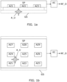
- FIG. 1a illustrates a side view of a block diagram form of a tongue based interface embodiment.
- FIG. 1b illustrates a top view a block diagram from of a tongue based interface of the same embodiment as FIG. 1a.
- FIG. 1a and 1b illustrate the elements of a tongue sensor device embodiment which is arranged to be fastened on the upper cavity of the user's mouth, so as to allow the user to manipulate the activation unit A_U, preferably a metallic halfsphere, by the user's tongue to activate the desired one of the activation zones AZ1-AZ9 of the sensor panel SP.
- the tongue sensor device has a sensor panel SP, guide structure GS, activation unit A_U and electronic circuit EC which are all integrated to form one single unit or one single mouth piece to enter the user's mouth.
- the user does not need any invasively tongue mounted activation unit to user the tongue based interface.
- a tongue based interface with a mouth piece with an inductive sensor panel and electronic circuit with a wireless communication interface is commercially available, and the sensor panel SP and electronic circuit EC according to the invention may be implemented by these already available parts.
- the novel feature of the invention is the guide structure GS, preferably mounted to the structure of the sensor panel SP, wherein the guide structure GS carries the activation unit A_U movably in a plane upon manipulation by the user's tongue, preferably a plane parallel with a plane where the activation zones AZ1-AZ9 of the sensor panel SP located, and to allow the activation unit A_U to be moved at a distance from the activation zones AZ1-AZ9. This movability is indicated by the double arrows on the activation unit A_U.
- the guide structure GS allows the activation unit A_U to move in a direction towards the activation zone AZ1-AZ9 by manipulation of the user's tongue, thereby bringing the activation unit A_U so close to one or more coils related to the activation zone AZ1-AZ9 that the electronic circuit EC will detect activation of the activation zone AZ-AZ9.
- the guide structure GS will allow 2D movement of the activation unit A_U without activation, and by the user's tongue pressing the activation unit A_U upwards towards the sensor panel, the resulting activation of the electrical coil(s) can be detected by the electronic circuit EC.
- the electronic circuit EC comprises a Radio Frequency (RF) transmitter arranged to transmit an output in the form of a wireless RF signal RF_O with a representation of data indicating activation of any one of the activation zones AZ1-AZ9 and also indication of which one of the activation zones AZ1-AZ9 which has been activated.
- RF Radio Frequency
- the free 2D movement of the activation unit A_U can be provided by a guide structure GS which carries the activation unit A_U hanging by gravity, i.e. away from the sensor panel SP, and wherein the guide structure GS allows free up and down movement, to allow the user's tongue to lift the activation unit A_U up towards the sensor panel SP for activation of the desired activation zone AZ1-AZ9.
Landscapes
- Engineering & Computer Science (AREA)
- Theoretical Computer Science (AREA)
- General Engineering & Computer Science (AREA)
- Human Computer Interaction (AREA)
- Health & Medical Sciences (AREA)
- Heart & Thoracic Surgery (AREA)
- General Physics & Mathematics (AREA)
- Biomedical Technology (AREA)
- Physics & Mathematics (AREA)
- Vascular Medicine (AREA)
- Life Sciences & Earth Sciences (AREA)
- Animal Behavior & Ethology (AREA)
- General Health & Medical Sciences (AREA)
- Public Health (AREA)
- Veterinary Medicine (AREA)
- Prostheses (AREA)
Claims (15)
- Zungenbasierte Schnittstelle (T_I), die angeordnet ist, um eine Eingabe von einem Benutzer mittels Aktivierung durch die Zunge des Benutzers zu empfangen, wobei die zungenbasierte Schnittstelle Folgendes umfasst:- Zungensensorvorrichtung, die zur Position in der Mundhöhle des Benutzers angeordnet ist, wobei die Zungensensorvorrichtung Folgendes umfasst:- eine Sensorplatte (SP), umfassend eine 2D-Anordnung einer Vielzahl von Aktivierungszonen (AZ1, AZ2, AZ3) und zugehörigen elektrischen Spulen, wobei die Sensorplatte (SP) angeordnet ist, um in einem oberen Teil der Mundhöhle des Benutzers positioniert zu werden,dadurch gekennzeichnet, dassdie zungenbasierte Schnittstelle (T_I) ferner Folgendes umfasst:- eine Führungsstruktur (GS), die angeordnet ist, um eine eisenhaltige oder metallische Aktivierungseinheit (A_U), die in einer Ebene beweglich ist, bei einer Betätigung durch die Zunge des Benutzers zu tragen, um es dem Benutzer zu ermöglichen, die Aktivierungseinheit (A_U) in Bezug auf die 2D-Anordnung der Vielzahl von Aktivierungszonen (AZ1, AZ2, AZ3) zu positionieren, und wobei die Führungsstruktur (GS) es der Aktivierungseinheit (A_U) ermöglicht, sich in einer Richtung aus der Ebene heraus zu bewegen, um es der Zunge des Benutzers zu ermöglichen, die Aktivierungseinheit (A_U) nahe einer der Aktivierungszonen (AZ1, AZ2, AZ3) zur Aktivierung der einen Aktivierungszone (AZ1, AZ2, AZ3) zu betätigen, und- eine elektronische Schaltung (EC), die mit den elektrischen Spulen der Sensorplatte (SP) verbunden und angeordnet ist, um eine Aktivierung von einer oder mehreren der Aktivierungszonen (AZ1, AZ2, AZ3) zu erfassen, die durch die Aktivierungseinheit (A_U) mittels der zugehörigen elektrischen Spulen verursacht werden, und wobei die elektronische Schaltung (EC) angeordnet ist, um einen drahtlosen oder drahtgebundenen Ausgang (RF_O) entsprechend zu erzeugen.
- Zungenbasierte Schnittstelle (T_I) nach Anspruch 1, wobei die Führungsstruktur (GS) ein Element umfasst, das in Bezug auf die Sensorplatte (SP) befestigt montiert ist.
- Zungenbasierte Schnittstelle (T_I) nach Anspruch 1 oder 2, wobei die Führungsstruktur (GS) einen Rahmen mit einer Vielzahl von Elementen umfasst und wobei die Aktivierungseinheit (A_U) durch ein erstes Element des Rahmens getragen wird.
- Zungenbasierte Schnittstelle (T_I) nach Anspruch 3, wobei die Aktivierungseinheit (A_U) angeordnet ist, um sich entlang des ersten Elements des Rahmens zu bewegen.
- Zungenbasierte Schnittstelle (T_I) nach Anspruch 3 oder 4, wobei das erste Element in Bezug auf mindestens ein weiteres Element des Rahmens in mindestens einer Dimension beweglich angeordnet ist.
- Zungenbasierte Schnittstelle (T_I) nach Anspruch 5, wobei der Rahmen zwei Stäbe umfasst und wobei das erste Element angeordnet ist, um entlang der Stäbe zu gleiten.
- Zungenbasierte Schnittstelle (T_I) nach Anspruch 6, wobei das erste Element ein gebogenes Element umfasst und mit den zwei Stangen verbunden ist, um zu ermöglichen, dass sich die Aktivierungseinheit (A_U) in eine Richtung aus der Ebene heraus bewegt.
- Zungenbasierte Schnittstelle (T_I) nach einem der Ansprüche 1 oder 2, wobei die Führungsstruktur (GS) ein oder mehrere teleskopische Elemente umfasst, die an einem Ende mit der Aktivierungseinheit (A_U) verbunden sind.
- Zungenbasierte Schnittstelle (T_I) nach einem der vorhergehenden Ansprüche, wobei die Führungsstruktur (GS) zum Platzieren der Aktivierungseinheit (A_U) in einer Ruhe- oder Parkposition weg von der Sensorplatte (SP) konfiguriert ist.
- Zungenbasierte Schnittstelle (T_I) nach einem der vorhergehenden Ansprüche, wobei die Zungensensorvorrichtung ein Befestigungselement umfasst, das angeordnet ist, um die Sensorplatte (SP) an einer Position in der oberen Mundhöhle des Benutzers zu befestigen.
- Zungenbasierte Schnittstelle (T_I) nach einem der vorhergehenden Ansprüche, wobei die Aktivierungseinheit (A_U) ein kugelförmiges, halbkugelförmiges oder zylindrisches eisenhaltiges oder metallisches Element ist.
- Zungenbasierte Schnittstelle (T_I) nach einem der vorhergehenden Ansprüche, wobei die elektronische Schaltung (EC) einen drahtlosen Sender umfasst, der angeordnet ist, um ein Hochfrequenzsignal (RF_O) zu übertragen, das eine Aktivierung der Aktivierungszonen (AZ1, AZ2, AZ3) der Sensorplatte (SP) angibt.
- Verfahren zur zungenbasierten Steuerung einer zungenbasierten Schnittstelle nach Anspruch 1,- Bereitstellen einer Zungensensorvorrichtung in der Mundhöhle des Benutzers, wobei die Zungensensorvorrichtung eine Sensorplatte (SP) umfasst, die eine 2D-Anordnung einer Vielzahl von Aktivierungszonen (AZ1, AZ2, AZ3) und zugehörigen elektrischen Spulen umfasst,dadurch gekennzeichnet, dass
das Verfahren ferner Folgendes umfasst:- Tragen, mittels einer Führungsstruktur (GS), einer eisenhaltigen oder metallischen Aktivierungseinheit (A_U), die beweglich ist, um der Zunge des Benutzers zu ermöglichen, die Aktivierungseinheit (A_U) nahe einer Aktivierungszone (AZ1, AZ2, AZ3) zur Aktivierung der einen Aktivierungszone (AZ1, AZ2, AZ3) zu betätigen, und- Erfassen der Aktivierung der einen Aktivierungszone (AZ1, AZ2, AZ3) unter Verwendung einer oder mehrerer der elektrischen Spulen und dementsprechend Generieren einer drahtgebundenen oder drahtlosen Ausgabe (RF_O). - System, umfassend:- eine zungenbasierte Schnittstelle (T_I) nach einem der Ansprüche 1-12 und- eine Vorrichtung (EXD), die angeordnet ist, um die drahtgebundene oder drahtlose Ausgabe von der zungenbasierten Schnittstelle (T_I) zu empfangen und eine oder mehrere Funktionen als Reaktion auf die drahtgebundene oder drahtlose Ausgabe zu steuern.
- System nach Anspruch 14, wobei die Vorrichtung (EXD) eines der Folgenden ist:
eine unterstützende Vorrichtung, ein Fahrzeug, eine Spielkonsole, ein Gebäudeteil, eine Tür oder ein Tor, ein Lüftungssystem, ein Werkzeug, eine medizinische Vorrichtung oder ein Teil einer medizinischen Vorrichtung oder eine Robotervorrichtung.
Applications Claiming Priority (2)
| Application Number | Priority Date | Filing Date | Title |
|---|---|---|---|
| DKPA202170463 | 2021-09-24 | ||
| PCT/DK2022/050196 WO2023046252A1 (en) | 2021-09-24 | 2022-09-23 | Non-invasive tongue based interface |
Publications (3)
| Publication Number | Publication Date |
|---|---|
| EP4404879A1 EP4404879A1 (de) | 2024-07-31 |
| EP4404879B1 true EP4404879B1 (de) | 2025-07-09 |
| EP4404879C0 EP4404879C0 (de) | 2025-07-09 |
Family
ID=83598507
Family Applications (1)
| Application Number | Title | Priority Date | Filing Date |
|---|---|---|---|
| EP22785919.6A Active EP4404879B1 (de) | 2021-09-24 | 2022-09-23 | Nichtinvasive zungebasierte schnittstelle |
Country Status (2)
| Country | Link |
|---|---|
| EP (1) | EP4404879B1 (de) |
| WO (1) | WO2023046252A1 (de) |
Family Cites Families (3)
| Publication number | Priority date | Publication date | Assignee | Title |
|---|---|---|---|---|
| AU4806890A (en) * | 1988-12-16 | 1990-07-10 | Zofcom, Inc. | Tongue activated communications controller |
| DE69616623T2 (de) * | 1995-03-31 | 2002-08-01 | International Business Machines Corp., Armonk | Intraorales Kommunkationssystem |
| WO2009138089A1 (en) | 2008-05-13 | 2009-11-19 | Aalborg Universitet | Inductive input device |
-
2022
- 2022-09-23 WO PCT/DK2022/050196 patent/WO2023046252A1/en not_active Ceased
- 2022-09-23 EP EP22785919.6A patent/EP4404879B1/de active Active
Also Published As
| Publication number | Publication date |
|---|---|
| WO2023046252A1 (en) | 2023-03-30 |
| EP4404879A1 (de) | 2024-07-31 |
| EP4404879C0 (de) | 2025-07-09 |
Similar Documents
| Publication | Publication Date | Title |
|---|---|---|
| US9827061B2 (en) | Touch-free catheter user interface controller | |
| KR101548156B1 (ko) | 촉감과 관절 저항감을 동시에 전달하는 무선 외골격 햅틱 인터페이스 장치 및 그 구성 방법 | |
| JP5725603B2 (ja) | 側面設置型力覚提示インターフェイス | |
| Ubeda et al. | Wireless and portable EOG-based interface for assisting disabled people | |
| KR101383421B1 (ko) | 식사보조를 위한 상지 재활 로봇 | |
| CN107019527A (zh) | 用于经直肠探头的机器人辅助控制的系统 | |
| JP2011516915A (ja) | モーションコンテンツベースの学習装置及び方法 | |
| US20160120664A1 (en) | Breath and head tilt controlled prosthetic limb | |
| JP2001282448A (ja) | 三次元入力装置 | |
| US11687073B2 (en) | Specialist control for a wheelchair | |
| EP3860815B1 (de) | Körperpflegevorrichtung | |
| KR101831602B1 (ko) | 영상 처리를 통해 정밀 제어하는 상지 재활 로봇 모듈 및 재활 로봇 시스템 | |
| AU2016210013B2 (en) | A force measurement mechanism | |
| WO2023046252A1 (en) | Non-invasive tongue based interface | |
| KR101383450B1 (ko) | 식사보조를 위한 상지 재활로봇 제어방법 | |
| CN107877501A (zh) | 机械手臂 | |
| US11672716B2 (en) | Overhead lift systems and methods | |
| EP4459425A1 (de) | Betriebsvorrichtung und betriebssystem | |
| EP3136969B1 (de) | Röntgensystem | |
| KR102177158B1 (ko) | 로봇 제어 시스템 | |
| KR102429231B1 (ko) | 웨어러블 장치를 이용한 식사 보조 방법 및 장치 | |
| KR101348940B1 (ko) | 로봇의 원격조작시 발생하는 물리적 상호작용 전달을 위한 감각 재현 시스템 | |
| Khan et al. | Tongue-supported human-computer interaction systems: a review | |
| KR101745860B1 (ko) | 능동형 상지 운동 보조장치 | |
| Al-Okby et al. | Low-cost Hybrid Wheelchair Controller for Quadriplegias and Paralysis Patients |
Legal Events
| Date | Code | Title | Description |
|---|---|---|---|
| STAA | Information on the status of an ep patent application or granted ep patent |
Free format text: STATUS: UNKNOWN |
|
| STAA | Information on the status of an ep patent application or granted ep patent |
Free format text: STATUS: THE INTERNATIONAL PUBLICATION HAS BEEN MADE |
|
| PUAI | Public reference made under article 153(3) epc to a published international application that has entered the european phase |
Free format text: ORIGINAL CODE: 0009012 |
|
| STAA | Information on the status of an ep patent application or granted ep patent |
Free format text: STATUS: REQUEST FOR EXAMINATION WAS MADE |
|
| 17P | Request for examination filed |
Effective date: 20240417 |
|
| AK | Designated contracting states |
Kind code of ref document: A1 Designated state(s): AL AT BE BG CH CY CZ DE DK EE ES FI FR GB GR HR HU IE IS IT LI LT LU LV MC MK MT NL NO PL PT RO RS SE SI SK SM TR |
|
| DAV | Request for validation of the european patent (deleted) | ||
| DAX | Request for extension of the european patent (deleted) | ||
| GRAP | Despatch of communication of intention to grant a patent |
Free format text: ORIGINAL CODE: EPIDOSNIGR1 |
|
| STAA | Information on the status of an ep patent application or granted ep patent |
Free format text: STATUS: GRANT OF PATENT IS INTENDED |
|
| INTG | Intention to grant announced |
Effective date: 20250204 |
|
| GRAS | Grant fee paid |
Free format text: ORIGINAL CODE: EPIDOSNIGR3 |
|
| GRAA | (expected) grant |
Free format text: ORIGINAL CODE: 0009210 |
|
| STAA | Information on the status of an ep patent application or granted ep patent |
Free format text: STATUS: THE PATENT HAS BEEN GRANTED |
|
| AK | Designated contracting states |
Kind code of ref document: B1 Designated state(s): AL AT BE BG CH CY CZ DE DK EE ES FI FR GB GR HR HU IE IS IT LI LT LU LV MC MK MT NL NO PL PT RO RS SE SI SK SM TR |
|
| REG | Reference to a national code |
Ref country code: GB Ref legal event code: FG4D |
|
| REG | Reference to a national code |
Ref country code: CH Ref legal event code: EP |
|
| REG | Reference to a national code |
Ref country code: IE Ref legal event code: FG4D |
|
| REG | Reference to a national code |
Ref country code: DE Ref legal event code: R096 Ref document number: 602022017425 Country of ref document: DE |
|
| U01 | Request for unitary effect filed |
Effective date: 20250807 |
|
| U07 | Unitary effect registered |
Designated state(s): AT BE BG DE DK EE FI FR IT LT LU LV MT NL PT RO SE SI Effective date: 20250819 |
|
| U20 | Renewal fee for the european patent with unitary effect paid |
Year of fee payment: 4 Effective date: 20250924 |
|
| PG25 | Lapsed in a contracting state [announced via postgrant information from national office to epo] |
Ref country code: IS Free format text: LAPSE BECAUSE OF FAILURE TO SUBMIT A TRANSLATION OF THE DESCRIPTION OR TO PAY THE FEE WITHIN THE PRESCRIBED TIME-LIMIT Effective date: 20251109 |
|
| PG25 | Lapsed in a contracting state [announced via postgrant information from national office to epo] |
Ref country code: NO Free format text: LAPSE BECAUSE OF FAILURE TO SUBMIT A TRANSLATION OF THE DESCRIPTION OR TO PAY THE FEE WITHIN THE PRESCRIBED TIME-LIMIT Effective date: 20251009 |
|
| PG25 | Lapsed in a contracting state [announced via postgrant information from national office to epo] |
Ref country code: HR Free format text: LAPSE BECAUSE OF FAILURE TO SUBMIT A TRANSLATION OF THE DESCRIPTION OR TO PAY THE FEE WITHIN THE PRESCRIBED TIME-LIMIT Effective date: 20250709 |
|
| PG25 | Lapsed in a contracting state [announced via postgrant information from national office to epo] |
Ref country code: GR Free format text: LAPSE BECAUSE OF FAILURE TO SUBMIT A TRANSLATION OF THE DESCRIPTION OR TO PAY THE FEE WITHIN THE PRESCRIBED TIME-LIMIT Effective date: 20251010 |
|
| PG25 | Lapsed in a contracting state [announced via postgrant information from national office to epo] |
Ref country code: PL Free format text: LAPSE BECAUSE OF FAILURE TO SUBMIT A TRANSLATION OF THE DESCRIPTION OR TO PAY THE FEE WITHIN THE PRESCRIBED TIME-LIMIT Effective date: 20250709 |
|
| PG25 | Lapsed in a contracting state [announced via postgrant information from national office to epo] |
Ref country code: RS Free format text: LAPSE BECAUSE OF FAILURE TO SUBMIT A TRANSLATION OF THE DESCRIPTION OR TO PAY THE FEE WITHIN THE PRESCRIBED TIME-LIMIT Effective date: 20251009 |
|
| PG25 | Lapsed in a contracting state [announced via postgrant information from national office to epo] |
Ref country code: ES Free format text: LAPSE BECAUSE OF FAILURE TO SUBMIT A TRANSLATION OF THE DESCRIPTION OR TO PAY THE FEE WITHIN THE PRESCRIBED TIME-LIMIT Effective date: 20250709 |
|
| PG25 | Lapsed in a contracting state [announced via postgrant information from national office to epo] |
Ref country code: SM Free format text: LAPSE BECAUSE OF FAILURE TO SUBMIT A TRANSLATION OF THE DESCRIPTION OR TO PAY THE FEE WITHIN THE PRESCRIBED TIME-LIMIT Effective date: 20250709 |
|
| PG25 | Lapsed in a contracting state [announced via postgrant information from national office to epo] |
Ref country code: CZ Free format text: LAPSE BECAUSE OF FAILURE TO SUBMIT A TRANSLATION OF THE DESCRIPTION OR TO PAY THE FEE WITHIN THE PRESCRIBED TIME-LIMIT Effective date: 20250709 |
|
| PG25 | Lapsed in a contracting state [announced via postgrant information from national office to epo] |
Ref country code: SK Free format text: LAPSE BECAUSE OF FAILURE TO SUBMIT A TRANSLATION OF THE DESCRIPTION OR TO PAY THE FEE WITHIN THE PRESCRIBED TIME-LIMIT Effective date: 20250709 |
|
| REG | Reference to a national code |
Ref country code: CH Ref legal event code: H13 Free format text: ST27 STATUS EVENT CODE: U-0-0-H10-H13 (AS PROVIDED BY THE NATIONAL OFFICE) Effective date: 20260504 |
|
| PLBE | No opposition filed within time limit |
Free format text: ORIGINAL CODE: 0009261 |
|
| STAA | Information on the status of an ep patent application or granted ep patent |
Free format text: STATUS: NO OPPOSITION FILED WITHIN TIME LIMIT |