EP4404844B1 - Tomosyntheseverstärkungskalibrierung und bildkorrektur - Google Patents
Tomosyntheseverstärkungskalibrierung und bildkorrektur Download PDFInfo
- Publication number
- EP4404844B1 EP4404844B1 EP22794000.4A EP22794000A EP4404844B1 EP 4404844 B1 EP4404844 B1 EP 4404844B1 EP 22794000 A EP22794000 A EP 22794000A EP 4404844 B1 EP4404844 B1 EP 4404844B1
- Authority
- EP
- European Patent Office
- Prior art keywords
- dose
- gain
- low
- image
- tomosynthesis
- Prior art date
- Legal status (The legal status is an assumption and is not a legal conclusion. Google has not performed a legal analysis and makes no representation as to the accuracy of the status listed.)
- Active
Links
Images




Classifications
-
- A—HUMAN NECESSITIES
- A61—MEDICAL OR VETERINARY SCIENCE; HYGIENE
- A61B—DIAGNOSIS; SURGERY; IDENTIFICATION
- A61B6/00—Apparatus or devices for radiation diagnosis; Apparatus or devices for radiation diagnosis combined with radiation therapy equipment
- A61B6/58—Testing, adjusting or calibrating thereof
- A61B6/582—Calibration
- A61B6/585—Calibration of detector units
-
- G—PHYSICS
- G06—COMPUTING OR CALCULATING; COUNTING
- G06T—IMAGE DATA PROCESSING OR GENERATION, IN GENERAL
- G06T5/00—Image enhancement or restoration
- G06T5/50—Image enhancement or restoration using two or more images, e.g. averaging or subtraction
-
- A—HUMAN NECESSITIES
- A61—MEDICAL OR VETERINARY SCIENCE; HYGIENE
- A61B—DIAGNOSIS; SURGERY; IDENTIFICATION
- A61B6/00—Apparatus or devices for radiation diagnosis; Apparatus or devices for radiation diagnosis combined with radiation therapy equipment
- A61B6/02—Arrangements for diagnosis sequentially in different planes; Stereoscopic radiation diagnosis
- A61B6/025—Tomosynthesis
-
- A—HUMAN NECESSITIES
- A61—MEDICAL OR VETERINARY SCIENCE; HYGIENE
- A61B—DIAGNOSIS; SURGERY; IDENTIFICATION
- A61B6/00—Apparatus or devices for radiation diagnosis; Apparatus or devices for radiation diagnosis combined with radiation therapy equipment
- A61B6/50—Apparatus or devices for radiation diagnosis; Apparatus or devices for radiation diagnosis combined with radiation therapy equipment specially adapted for specific body parts; specially adapted for specific clinical applications
- A61B6/502—Apparatus or devices for radiation diagnosis; Apparatus or devices for radiation diagnosis combined with radiation therapy equipment specially adapted for specific body parts; specially adapted for specific clinical applications for diagnosis of breast, i.e. mammography
-
- A—HUMAN NECESSITIES
- A61—MEDICAL OR VETERINARY SCIENCE; HYGIENE
- A61B—DIAGNOSIS; SURGERY; IDENTIFICATION
- A61B6/00—Apparatus or devices for radiation diagnosis; Apparatus or devices for radiation diagnosis combined with radiation therapy equipment
- A61B6/58—Testing, adjusting or calibrating thereof
- A61B6/582—Calibration
-
- A—HUMAN NECESSITIES
- A61—MEDICAL OR VETERINARY SCIENCE; HYGIENE
- A61B—DIAGNOSIS; SURGERY; IDENTIFICATION
- A61B8/00—Diagnosis using ultrasonic, sonic or infrasonic waves
- A61B8/08—Clinical applications
- A61B8/0825—Clinical applications for diagnosis of the breast, e.g. mammography
-
- G—PHYSICS
- G06—COMPUTING OR CALCULATING; COUNTING
- G06T—IMAGE DATA PROCESSING OR GENERATION, IN GENERAL
- G06T2207/00—Indexing scheme for image analysis or image enhancement
- G06T2207/10—Image acquisition modality
- G06T2207/10116—X-ray image
-
- G—PHYSICS
- G06—COMPUTING OR CALCULATING; COUNTING
- G06T—IMAGE DATA PROCESSING OR GENERATION, IN GENERAL
- G06T2207/00—Indexing scheme for image analysis or image enhancement
- G06T2207/20—Special algorithmic details
- G06T2207/20016—Hierarchical, coarse-to-fine, multiscale or multiresolution image processing; Pyramid transform
-
- G—PHYSICS
- G06—COMPUTING OR CALCULATING; COUNTING
- G06T—IMAGE DATA PROCESSING OR GENERATION, IN GENERAL
- G06T2207/00—Indexing scheme for image analysis or image enhancement
- G06T2207/20—Special algorithmic details
- G06T2207/20212—Image combination
- G06T2207/20216—Image averaging
-
- G—PHYSICS
- G06—COMPUTING OR CALCULATING; COUNTING
- G06T—IMAGE DATA PROCESSING OR GENERATION, IN GENERAL
- G06T2207/00—Indexing scheme for image analysis or image enhancement
- G06T2207/30—Subject of image; Context of image processing
- G06T2207/30004—Biomedical image processing
- G06T2207/30068—Mammography; Breast
Definitions
- Breast cancer and other breast lesions continue to be a significant threat to women's health.
- X-ray mammography and breast tomosynthesis are the most widely used tools for early detection, screening, and diagnosis.
- Breast tomosynthesis is a technique that allows physicians to view multiple images of the breast rather than a single image available from a conventional mammogram.
- Embodiments of the disclosure are directed to a tomosynthesis methods and systems for gain calibration and correction of breast images in association with breast tomosynthesis methods.
- a method for gain calibration at a plurality of imaging parameters for a tomosynthesis sweep includes: performing one or more tomosynthesis sweeps to acquire a plurality of tomosynthesis projection x-ray images, each of the plurality of tomosynthesis projection x-ray images associated with one of the plurality of imaging parameters; generating a high-dose x-ray image by averaging the plurality of tomosynthesis projection x-ray images; generating a high-dose gain map associated with the high-dose x-ray image; generating a plurality of low-dose gain maps, each of the plurality of low-dose gain maps associated with one of the plurality of tomosynthesis projection x-ray images associated with one of the plurality of imaging parameters; decomposing each of the plurality of low-dose gain maps into a plurality of component levels; extracting low-resolution components from the plurality of component levels for each of the plurality of low-dose gain maps; and for each of the plurality of imaging parameters,
- a tomosynthesis system for gain calibration at a plurality of projection angles.
- the system includes: an image acquisition unit comprising an x-ray source and an x-ray image receptor, wherein the image acquisition unit acquires projection x-ray images of an object at the plurality of projection angles; a processor; memory including instructions that when executed by the processor cause the processor to: perform one or more tomosynthesis sweeps to acquire a plurality of tomosynthesis projection x-ray images, each of the plurality of tomosynthesis projection x-ray images associated with one of the plurality of projection angles; generate a high-dose x-ray image by averaging the plurality of tomosynthesis projection x-ray images; generate a high-dose gain map associated with the high-dose x-ray image; decompose the high-dose gain map into a first plurality of component levels; extract a high-resolution component from the first plurality of component levels; generate a plurality of low-dose gain maps, each of the plurality of
- a method for gain calibration at a plurality of projection angles for a tomosynthesis sweep includes: performing one or more tomosynthesis sweeps to acquire a plurality of tomosynthesis projection x-ray images, each of the plurality of tomosynthesis projection x-ray images associated with one of the plurality of projection angles; generating a high-dose x-ray image by averaging the plurality of tomosynthesis projection x-ray images; generating a high-dose gain map associated with the high-dose x-ray image; decomposing the high-dose gain map into a first plurality of component levels; extracting a high-resolution component from the first plurality of component levels; generating a plurality of low-dose gain maps, each of the plurality of low-dose gain maps associated with one of the plurality of tomosynthesis projection x-ray images associated with one of the plurality of projection angles; decomposing each of the plurality of low-dose gain maps into a second plurality of component levels; extract
- Digital tomosynthesis is a "three-dimensional" process in which several two-dimensional projection views are acquired at respective different angles but at lower x-ray dose each compared to a conventional mammogram, and are reconstructed into tomosynthesis slice views that can be along any desired plane in the breast and can represent any thickness of breast tissue.
- the combined reconstructed tomosynthesis image set represents the entire thickness of the breast, in a stack of two-dimensional images.
- the breast is immobilized or compressed to the same or lesser extent than in conventional mammography.
- the imaging receptor may comprise a two-dimensional array of millions of imaging pixels, and there may be inherent differences in the response of different imaging pixels to impinging x-rays. When all imaging pixels receive the same x-ray exposure, ideally each should provide the same electrical output signal (pixel value).
- the flat panel imager is exposed to an x-ray field through a phantom that simulates a patient's breast and has a generally uniform thickness and is made of a uniform material, the differences between pixel values are recorded, and a gain correction map is generated that accounts for such differences. This can be done periodically during the service life of the flat panel x-ray receptor.
- the gain map is stored in the imaging system and, when x-ray images of a patient's breast are taken during actual imaging procedures, software in the system corrects the acquired pixel values according to the gain map to bring them closer to the pixel values that would have been produced if all the imaging pixels had the same response to uniform exposure to x-ray energy.
- Gain calibration For conventional mammography, usually one gain map is acquired for each viewing mode or x-ray filter mode. Gain calibration thus can be used to compensate for sensitivity differences between detector pixels and non-uniform x-ray field intensity given a particular physical relationship between the x-ray source and imaging detector.
- tomosynthesis imaging is characterized by a much greater number of changes in x-ray source projection angle during x-ray exposure, much lower x-ray exposure of the breast at any one of the projection angles, and other significant differences from conventional mammography imaging.
- gain maps typical for conventional mammography cannot be expected to work well in tomosynthesis image acquisition and image correction, particularly if the tomosynthesis projection angles may change depending on imaging protocol or decisions or preferences of the health professional (e.g., an imaging technologist) in charge.
- One solution for gain correcting images obtained during the tomosynthesis process includes obtaining gain map images at each view angle in order to make gain-corrected images flat at all angles.
- tomosynthesis methods may include obtaining images at 15 or sometimes even 60 individual angles. In such a case, a gain map for each of these angles is required in order to perform the appropriate gain correction.
- Each gain map requires high x-ray dose exposures to maintain good photon statistics to reduce image noise, which makes gain calibration a very high tube loading procedure. Therefore, there is a need for a better and more efficient gain mapping method.
- Gain mapping consists of contributions from different sources in a system, e.g., detector pixel to pixel variation effect, tube heel effect, view angle effect, filter, anti-scatter grid, kilovoltage peak (KVp), phantom thickness, etc.
- detector pixel-to-pixel variations are the most dose-demanding task and require high-dose exposures to reliably measure them.
- Other components of the final gain map carry low frequency information and do not require high dose exposures for measurements.
- a multi-scale decomposition can be performed to analyze gain maps at different scales and layers.
- a gain map may be the product of high-resolution and low-resolution component maps.
- the high-resolution detailed images can look flat and may not contain any information on image tilt related to factors like the heel effect and view angle effect.
- the high-resolution layers may mainly contain detector pixel-to-pixel variation information.
- low-resolution residue images may clearly show heel effect, view angle effect and other low frequency factors.
- the low-resolution residue images may be obtained using low dose exposures.
- the low-resolution layers may contain tube heel effect, view angle effect, filter effect, anti-scatter grid effect, KVp effect, and phantom thickness effect.
- the component maps of a tomosynthesis gain map at two different angles may typically look identical except for the angle map.
- the components maps associated with the detector pixel-to-pixel variation, tube heel effect, filter, anti-scatter grid, KVp, and phantom thickness effects are almost identical at different angles.
- the main difference between tomosynthesis gain maps at two different angles is the angle map.
- the disclosed system and method may combine all components other than the angle map together and treat it as a common reference map.
- the common reference map may then be combined with each angle map associated with each of the angles of the tomosynthesis process.
- the disclosed system and method helps avoid high x-ray dose exposures at each view angle while still maintaining good photon statistics to reduce image noise.
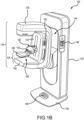
- FIG. 1A is a schematic view of an exemplary imaging system 100 and FIG. 1B is a perspective view of the imaging system 100. Referring concurrently to FIGS. 1A and 1B , not every element described below is depicted in both figures.
- the imaging system 100 immobilizes a patient's breast 102 for x-ray imaging (either or both of mammography, tomosynthesis, or other imaging modalities) via a breast compression immobilizer unit 104 that includes a static breast support platform 106 and a moveable paddle 108.
- Different paddles, each having different purposes, are known in the art. Certain examples paddles are also described herein for context.
- the breast support platform 106 and the paddle 108 each have a compression surface 110 and 112, respectively, that move towards each other to compress, immobilize, stabilize, or otherwise hold and secure the breast 102 during imaging procedures.
- the compression surface 110, 112 is exposed so as to directly contact the breast 102.
- Either or both of these compression surfaces 110, 112 may be rigid plastic, a flexible plastic, a resilient foam, a mesh or screen, and so on.
- the platform 106 also houses an image receptor 116 and, optionally, a tilting mechanism 118, and optionally an anti-scatter grid (not depicted, but disposed above the image receptor 116).
- the immobilizer unit 104 is in a path of an imaging beam 120 emanating from x-ray source 122, such that the beam 120 impinges on the image receptor 116.
- the immobilizer unit 104 is supported on a first support arm 124 via a compression arm 134, which is configured to be raised and lowered along the support arm 124.
- the x-ray source 122 is supported on a second support arm, also referred to as a tube head 126.
- support arms 124 and 126 can rotate as a unit about an axis 128 between different imaging orientations such as CC and MLO, so that the system 100 can take a mammogram projection image at each orientation.
- the image receptor 116 remains in place relative to the platform 106 while an image is taken.
- the immobilizer unit 104 releases the breast 102 for movement of arms 124, 126 to a different imaging orientation.
- the support arm 124 stays in place, with the breast 102 immobilized and remaining in place, while at least the second support arm 126 rotates the x-ray source 122 relative to the immobilizer unit 104 and the compressed breast 102 about the axis 128.
- the system 100 takes plural tomosynthesis projection images of the breast 102 at respective angles of the beam 120 relative to the breast 102.
- the image receptor 116 may be tilted relative to the breast support platform 106 and in sync with the rotation of the second support arm 126.
- the tilting can be through the same angle as the rotation of the x-ray source 122, but may also be through a different angle selected such that the beam 120 remains substantially in the same position on the image receptor 116 for each of the plural images.
- the tilting can be about an axis 130, which can but need not be in the image plane of the image receptor 116.
- the tilting mechanism 118 that is coupled to the image receptor 116 can drive the image receptor 116 in a tilting motion.
- the breast support platform 106 can be horizontal or can be at an angle to the horizontal, e.g., at an orientation similar to that for conventional MLO imaging in mammography.
- the system 100 can be solely a mammography system, a CT system, or solely a tomosynthesis system, other modalities such as ultrasound, or a "combo" system that can perform multiple forms of imaging.
- An example of a system has been offered by the assignee hereof under the trade name Selenia Dimensions.
- the image receptor 116 When the system is operated, the image receptor 116 produces imaging information in response to illumination by the imaging beam 120, and supplies it to an image processor 132 for processing and generating breast x-ray images.
- a system control and work station unit 138 including software controls the operation of the system and interacts with the operator to receive commands and deliver information including processed-ray images.
- the system control and work station unit 138 may include an image correction engine that may be configured to generate gain correction maps and gain correct breast x-ray images based on the generated gain correction maps. The configuration of the image correction engine is described in greater detail in relation to FIG. 2 .
- the imaging system 100 includes a floor mount or base 140 for supporting the imaging system 100 on a floor.
- a gantry 142 extends upwards from the floor mount 140 and rotatably supports both the tube head 208 and a support arm 210.
- the tube head 126 and support arm 124 are configured to rotate discretely from each other and may also be raised and lowered along a face 144 of the gantry 142 so as to accommodate patients of different heights.
- the x-ray source 122 is disposed within the tube head 208. Together, the tube head 126 and support arm 124 may be referred to as a C-arm 144.
- a number of interfaces and display screens are disposed on the imaging system 100. These include a foot display screen 146, a gantry interface 148, a support arm interface 150, and a compression arm interface 152.
- the various interfaces 148, 150, and 152 may include one or more tactile buttons, knobs, switches, as well as one or more display screens, including capacitive touch screens with graphic user interfaces (GUIs) so as to enable user interaction with and control of the imaging system 100.
- GUIs graphic user interfaces
- the foot display screen 146 is primarily a display screen, though a capacitive touch screen might be utilized if required or desired.
- FIG. 2 illustrates an example configuration 200 of an image correction engine 202 of the system of FIG. 1A .
- the image correction engine 202 may be configured within the workstation 138 of the imaging system 100.
- the description of FIG. 2 refers to components depicted in FIGS. 1A and 1B and are numbered accordingly.
- the image correction engine 202 may be configured to include an image acquisition module 204, a high-dose image generation module 206 and a gain map generation module 208. Other types of modules are also possible.
- the image acquisition module 204 may be configured to cause the imaging system 100 to acquire x-ray images of a phantom or a patient's breast at a plurality of imaging parameters as required for a tomosynthesis process.
- the example configuration 200 is largely described in association with gain calibration at imaging parameters that primarily includes the projection angle, other types of imaging parameters can also be used in the methods for gain calibration.
- the imaging parameter can be one of: kVp, filter material type, breast thickness, and grid position. Other types of imaging parameters are also possible.
- the image acquisition module 204 may cause the imaging system 100 to perform tomosynthesis data acquisition at a plurality of projection angles.
- the image receptor 116 may move relative to the immobilizer unit 104 during tomosynthesis data acquisition.
- the image receptor 115 may move differently or not at all.
- the motion may be motorized.
- the motion of the x-ray source 122 can be continuous or the x-ray source can stop and emit imaging x-rays at one projection angle before moving to another projection angle.
- Image receptor 116 may provide projection image data in the form of an array of pixel values related to incident x-ray energy.
- a calibration phantom can be secured in the immobilizer unit 104, in a position similar to that of a patient's breast when x-rays of a patient's breast are taken.
- the image acquisition module 204 may then cause the imaging system to perform the tomosynthesis data acquisition associated with the phantom at a plurality of projection angles.
- the patient's breast may be secured in the immobilizer unit 104.
- the image acquisition module 204 may then cause the imaging system 100 to perform the tomosynthesis data acquisition associated with the patient's breast at a plurality of projection angles.
- the high-dose image generation module 206 may be configured to generate a high-dose x-ray image from the plurality of tomosynthesis x-ray projection images of the phantom that were acquired by the image acquisition module 204 at the plurality of projection angles.
- the generated high-dose x-ray image may be used by the gain map generation module 208 in generating a gain correction map.
- the imaging system 100 may be configured to perform the tomosynthesis imaging of a phantom at 15 projection angles.
- the imaging system 100 performing the tomosynthesis imaging will generate 15 x-ray images of the phantom.
- each of the 15 images may appear "noisy" since the number of photons per pixel is relatively low due to the low-dose nature of the scans.
- the x-ray exposure for each view is 8mAs and the photon number for each pixel in a detector pixel array of 0.07mm x 0.07mm may only be about 2000 photons. This may cause the resulting x-ray images to appear noisy.
- the resulting gain map from the noisy images may include errors due to the low photon numbers.
- One solution to the above described problem related to noisy images may be solved by repeating the scans several times. If the tomosynthesis scans using 32kV and 120mAs were repeated 5 times and a three-neighbor view average were to be used, the photon number for each pixel in the gain map at each view angle may be 30k photons (2000 x 3 x 5). However, such a solution would require 5 tomosynthesis scans, which takes a considerable amount of time and negatively impacts the life of the x-ray tube.
- the disclosed high-dose image generation module 206 provides a solution for acquiring a high-dose image using only one tomosynthesis scan by using all the low-dose images together to create a new high-dose image.
- the high-dose image generation module 206 may combine and average images from each of the projection angles of a single tomosynthesis scan to create a high-dose image that does not include the noise seen in the low-dose images.
- a new high-dose image may be created by combining and averaging the 15 images.
- the newly created high-dose image would have a photon number per pixel of 30k photons (2000 x 15).
- the high-dose image generation module 206 may produce a high-dose image that can be used to generate a gain map that minimizes noise caused due to the low photon count.
- the Gain map generation module 208 is configured to create a gain correction map that may be used to gain correct patient breast images.
- the plurality of x-ray projection images of the phantom acquired by the image acquisition module 204 and the associated high-dose image generated by the high-dose image generation module 206 may be used to generate a gain correction map.
- a high-dose gain map derived from the high-dose image generated by combining the plurality of low-dose images acquired at the plurality of projection angles by the high-dose image generation module 206 may be less noisy, any gain corrections made using the high-dose gain map may look tilted or cupped. In other words, any image that is gain corrected by the high-dose gain map may not look flat since the high-dose gain map does not include the corrected angle information.
- each of the low-dose gain maps derived from the low-dose images, each acquired at each of the plurality of projection angles by the image acquisition module 204 may look flat due to the correct and accurate angle information, any gain corrections made using the low-dose gain maps may look noisy due to the low photon count of the image.
- the gain map generation module 208 may be configured to generate a low-dose gain map from each of the low-dose images corresponding to each of the projection angles of the tomosynthesis scan.
- the gain map generation module 208 may be configured to generate a high-dose gain map from the high-dose image that was generated by combining the plurality of low-dose images, as described above in relation to the high-dose image generation module 206. The final gain map may then be generated by combining components from the high-dose gain map with components from the low-dose gain maps.
- the image correction module 210 may be configured to receive the x-ray images of a patient's breast at each of the plurality of projection angles from the image acquisition module 204 and gain correct the received x-ray images of the patient's breast using the final gain map from the gain map generation module 208.
- the phantom is removed and a patient's breast is secured to the immobilizer unit 104.
- the image acquisition module 204 is then configured to x-ray the patient's breast using tomosynthesis imaging sequences.
- the tomosynthesis imaging sequence of a patient's breast generates projection x-ray images taken at a plurality of projection angles.
- the image correction module 210 receives the projection x-ray images of the patient's breast taken at a plurality of projection angles and final gain map from the gain map generation module 208. For each of the projection angles, the image correction module 210 may then use the final gain map to make adjustments to the gain values associated with each pixel of the projection x-ray images to create a gain-corrected set of projection x-ray images.
- FIG. 3 illustrates an example schematic representation of the components of a gain map.
- a gain map consists of contributions from different sources in a system.
- gain map 302 may be a product of individual components including detector pixel-to-pixel variation map 304, filter map 306, view angle map 308, kV map 310, grid map 312 and thickness map 314.
- gain map 302 may be a product of more, fewer or different individual components.
- a detector map may contain only the detector's pixel-to-pixel gain variations.
- the raw x-ray image may not look uniform in signal counts among all pixels. Since the x-ray to electrical signal conversion power are not exactly same among different pixels, each pixel generates electrical signals that may be different to other pixels in the detector. In other words, the detector gain at each pixel may be different.
- the map of the inverse of detector gain at each pixel may be referred as detector gain map, or detector map.
- the beam intensity from x-ray tube may not have uniform spatial distribution on detector surface, which is referred as heel effect.
- the heel effect may be affected by a few factors, including, kVp, filter, thickness, and grid.
- the factors that affect the heel effect ultimately also affect the system gain map.
- a perfect gain map compensates for the heel effects contributed by the factors including but not limited to, kVp, filter, thickness, and grid. Therefore, a gain map may include components related to each of these factors, and the gain map can be decomposed into a product of components that related to each of these factors.
- x-ray filter of different materials and thicknesses can modify the x-ray signal profile differently.
- a system gain map measured with a 0.05 mm thick rhodium filter may be different from the gain map measured with a 0.7 mm aluminum filter.
- X-ray tube kVp may also affect heel effect.
- x-ray intensity along chestwall to nipple direction drops more quickly at low kVp than at high kVp.
- Phantom thickness, and the presence of x-ray anti-scatter grid can also modify the intensity profile of x-ray beam on detector that affects the system gain map.
- the detector pixel-to-pixel gain variations 304 can be the most dose-demanding task.
- the detector pixel-to-pixel gain component is a high-resolution component that requires high-dose exposures to reliably measure.
- Other individual components 306-314 may only include low-resolution components and therefore do not require high-dose exposures to measure. Rather, individual components 306-314 can be reliably measured using low-dose exposures.
- the gain map 302 at each of the plurality of projection angles can be decomposed into a plurality of components, including high-resolution components and low-resolution components.
- the plurality of gain maps, each corresponding to a projection angle share common components.
- the detector pixel-to-pixel variation map 304, filter map 306, kV map 310, grid map 312 and thickness map 314 have very minimal variation at the different projection angles. Only the view angle 308 includes significant variations based on the projection angle. As a result, in some examples, the detector pixel-to-pixel variation map 304, filter map 306, kV map 310, grid map 312 and thickness map 314 may be extracted once and shared between the different gain maps. However, since the view angle map 308 varies as the projection angle changes, the view angle map 308 may be extracted for each of the projection angles.
- the final gain map may thus include a product of commonly shared angle-independent reference map, which includes the detector pixel-to-pixel variation map 304, filter map 306, kV map 310, grid map 312 and thickness map 314, and view angle map 308.
- a product of commonly shared angle-independent reference map which includes the detector pixel-to-pixel variation map 304, filter map 306, kV map 310, grid map 312 and thickness map 314, and view angle map 308.
- a desirable commercial implementation may include a common reference map that includes high and low resolution components with the exception of the angle map, but in other implementations, the common reference map may include a combination of high and low resolution components with the exception one of: the filter map, kV map, grid map and thickness map.
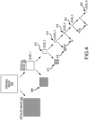
- FIG. 4 illustrates an example schematic representation of decomposition of a gain map into multi-scale components.
- a gain map may be viewed as a product of high-resolution and low-resolution component maps.
- a multi-scale decomposition process may be performed on an image to decompose the image into a detailed image and a residual image. The multi-scale decomposition process may be repeated several times on the resulting residual image to further extract the high-resolution components out of the image. At each level, the high-resolution components are extracted out to form the detailed image and leftover components of the image are used as the residual image from which the next level of decomposition is performed.
- the detailed images that are extracted out at the first few levels of decomposition are more sensitive to the high-dose components such as the detector pixel-to-pixel gain variation and less sensitive to low-dose components such as kV, filter, angle, grid and thickness.
- the detailed images that include the high-resolution components may be used to generate a high-dose gain map that includes the detector pixel-to-pixel variation data.
- the residual images of the last few levels of decomposition are less sensitive to dose and includes data regarding the low-resolution components, such as kV, filter, angle, grid and thickness.
- the residual images that include the low-resolution components may be used to generate a low-resolution gain map that includes the filter data, view angle data, kV data, grid data and thickness data.
- An original image 402 may include an x-ray projection image of a phantom at one of the plurality of projection angles.
- the original image 402 may be decomposed into a detailed image 404 and a residual image 406.
- the process of decomposition may be done using a multi-scale pyramidal decomposition process, a wavelet decomposition process, an FFT decomposition process. Other types of decomposition processes are also possible.
- the original image 402 may be decomposed into a first level detailed image 404 and a first level residual image 406 at a first level or level 1 of the decomposition process.
- the process may be repeated by decomposing the first level residual image 406 into a second level detailed image 408 and a second level residual image 410 for level 2 of the decomposition process.
- the decomposition process may continue as the second level residual image 410 is decomposed into a third level detailed image 412 and a third level residual image 414, the third level residual image 414 is decomposed into a fourth level detailed image 416 and a fourth level residual image 418 and the fourth level residual image 418 decomposed into a fifth level detailed image 420 and a fifth level residual image 422.
- the decomposition process may continue until the image can no longer be decomposed or until sufficient number of decomposition cycles have been achieved to extract the high-resolution and low-resolution components. For example, the decomposition process may continue until a N-th level detailed image 424 and N-th residual image 426 are generated.
- the low-dose x-ray projection images of the phantom acquired at the plurality of projection angles by the image acquisition module 204 is decomposed into multiple levels.
- the residual image from the last few levels of decomposition include low-resolution components that may be extracted for use in generating a final gain map as described in relation to gain map generation 208 of FIG. 2 .
- the level of the decomposed residual image from which a low-dose gain map is generated and low-resolution components are extracted may be selected based on an evaluation of whether enough of the high-resolution component of the residual image have been filtered out and whether the residual image includes enough resolution for extracting the low-resolution components.
- the most desirable level may be the third level to sixth level or last level of decomposition.
- the exact level of decomposition from which the low-resolution components are extracted may differ from image to image and between tomosynthesis processes.
- the high-dose x-ray projection image that is constructed by combining the plurality of low-dose x-ray projection images of the phantom by the image acquisition module 204 is decomposed into multiple levels.
- the detailed images from the first few levels of decomposition include high-resolution components that may be extracted for use in generating a final gain map as described in relation to gain map generation 208 of FIG. 2 .
- the high-resolution components may be extracted from a gain map generated from the first level detailed image 404. In other examples, the high-resolution components may be extracted from a gain map generated from a detailed image from another level other than the first level.
- the ideal level may be selected based on the level that provides the best high-resolution components.
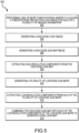
- FIG. 5 illustrates an example method 500 for gain calibration at a plurality of projection angles for a tomosynthesis sweep.
- the method 500 begins with operation 502.
- the imaging system 100 is used to perform one or more tomosynthesis sweeps to acquire a plurality of tomosynthesis projection x-ray images of a phantom.
- the acquired plurality of images are low-dose x-ray projection images.
- the image acquisition module 204 of the image correction engine 202 may be used to configure the acquisition of the plurality of images by the imaging system 100.
- a calibration phantom may be made of a uniform material with a substantially uniform thickness to simulate a patient's compressed breast.
- the phantom may be secured in the immobilizer unit 104 of the imaging system 100, in a position similar to that of a patient's breast when x-rays of a patient's breast are taken.
- the system 100 is operated in a tomosynthesis mode and an x-ray projection image of the phantom is taken at each of the plurality of imaging parameters.
- the imaging parameters may include projection angles.
- each projection x-ray image is represented by of pixel values related to the x-rays received at respective pixel positions of an array of imaging pixels in receptor 116.
- Operation 504 includes generating a high-dose x-ray image.
- the high-dose image generation module 206 of the image correction engine 202 may generate the high-dose x-ray image by combining and averaging the plurality of low-dose x-ray projection images that were acquired in operation 502. As further described in relation to FIG. 2 , combining and averaging the low-dose images results in a high-dose image that reduces noise caused due the low photon counts.
- Operation 506 includes generating a high-dose gain map from the high-dose x-ray image generated in operation 504.
- generating a high-dose gain map may include determining a mean signal count for an array of pixels associated with the high-dose x-ray image.
- the generating a high-dose gain map includes determining a raw signal count for each of the pixels from the array of pixels associated with the high dose x-ray image.
- the gain map may be generated by calculating the gain correction coefficient for each of the pixels in the array of pixels associated with the high-dose x-ray image and assembling the gain correction coefficient for each of the pixels in the array of pixels into the high-dose gain map.
- the gain correction coefficient may be a product of the mean signal count and an inverse of the raw signal count for a particular pixel. In other examples, the gain correction coefficients may be calculated in a different way.
- Operation 508 includes extracting high-resolution components from the high-dose gain map that was generated in operation 506.
- the gain map generation module 208 of the image correction engine 202 may use the decomposition process described in relation to FIG. 2 to decompose a high-dose gain map generated in operation 506 into multi-levels of components and extract the high-resolution components from the detailed image of the first or one of the first few levels of the decomposition process.
- the high-resolution component may only include the detector pixel-to-pixel variation data.
- the high-dose gain map may also include other types of both high-resolution and low-resolution data.
- High-resolution components may not be extracted from a high-dose gain map generated from the high-dose projection image at all and operation 508 may be skipped.
- the high-dose gain map itself may be used instead of extracting individual components of the gain map.
- the step of extracting the high-resolution components from the high-dose gain map may be unnecessary and the high-dose gain map itself may be used in the calculation of the final gain map. As such, the high-dose gain map may not need to be extracted and operation 508 may be skipped and operation 510 may be performed upon completion of operation 506.
- Operation 510 includes generating a plurality of low-dose gain maps, where each of the plurality of low-dose gain maps is associated with one of the plurality of projection x-ray images corresponding to one of the plurality of imaging parameters.
- the gain map generation module 208 of the image correction engine 202 may generate a gain map for each of the plurality of imaging parameters of the tomosynthesis scan based on the corresponding x-ray projection image acquired for that imaging parameter from operation 502.
- the process of generating a low-dose gain map may be the same or similar to the process used in generating the high-dose gain map in operation 506.
- One difference in the process may be that the gain map is generated from a low-dose x-ray projection image acquired in operation 502 rather than the high-dose projection image generated in operation 504.
- Operation 512 includes extracting low-resolution components from each of the plurality of low-dose gain maps generated in operation 510.
- the gain map generation module 208 of the image correction engine 202 may use the decomposition process described in relation to FIG. 2 to decompose a low-dose gain map generated in operation 510 into multi-levels of components and extract the low-resolution components from the detailed image of the last or one of the last few levels of the decomposition process.
- the low-resolution components may include a filter data, view angle data, kV data, grid data and thickness data.
- the low-dose gain map may also include other types of low-resolution data.
- high-resolution components of low dose gain map are not used at all in any step of final gain map generation since only the low-resolution components of low dose gain map are included and combined with high dose gain map or its high-resolution components. Therefore the decomposition process for low dose gain is frequently simplified as to skipping a full decomposition process to convert low dose gain map into each of its high- and low- resolution level components, and going directly to the N-th level low resolution residual component image. In such cases, more efficient processing algorithm other than full multi-scale deposition process can be selected to perform the calculation. For example, a 2x2, 4x4, 8x8, (and so on) pixel binning method may be used to derive the low-resolution component of low dose gain map.
- Operation 514 includes combining the high-resolution component of the high-dose gain map with each of the plurality of low-resolution components extracted from each of the low-dose gain maps to generate a final gain map for each of the plurality of imaging parameters.
- the gain map generation module 208 of the image correction engine 202 may generate a final gain map by combining the high-dose gain map or the high-resolution component of the high-dose gain map with the low-resolution components of the low-dose gain map acquired and generated in operations 502-512.
- the high-dose gain map or the high-resolution component of the high-dose gain map comprises the detector pixel-to-pixel variations.
- the imaging parameter includes the projection angle
- the detector pixel-to-pixel variations do not change at different projection angles.
- Most of the low-resolution components of the low-dose gain maps also do not change at different projection angles except for the angle component.
- the high-resolution components and low-resolution components that do not change between the different imaging parameters may be extracted out and a common reference gain map is generated.
- the remaining component or components of the low-dose gain map that differs between each of the imaging parameters may then be separately combined with the common reference gain map at each of the imaging parameters to generate a final gain map at each of the imaging parameters.
- the imaging parameter dependent component may be the view angle map.
- the imaging parameter dependent component may be the filter map, kV map, grid map or thickness map. Other options are also possible.
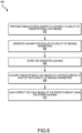
- FIG. 6 illustrates an example method 600 for image correction to compensate for gain offsets in a tomosynthesis process.
- the method 600 begins with operation 602.
- the imaging system 100 is used to perform one or more tomosynthesis sweeps to acquire a plurality of tomosynthesis projection x-ray images of a phantom, as described in relation to operation 502 of FIG. 5 .
- a gain map for each of the plurality of imaging parameters is generated from the x-ray projection images of the phantom that were acquired in operation 602.
- the process to normalize the image detector output among different pixels is called "gain correction.”
- the gain map is a map of gain correction coefficients associated with each pixel in the array of imaging pixels of the image receptor 116. The process of generating the gain map is described in greater detail in relation to FIGS. 2-5 .
- the generated gain map from operation 604 is stored.
- the generated gain map may be stored in the imaging system 100 itself.
- the generated gain map may be stored in a remote location accessible via a network and may be retrieved as required.
- tomosynthesis x-ray images of a patient's breast at each of the plurality of imaging parameters is acquired.
- the phantom may be removed, and a patient's breast may be secured in immobilizer unit 104 is x-rayed using tomosynthesis imaging sequences.
- the tomosynthesis imaging sequence of a patient's breast may generate projection x-ray images taken at a plurality of projection angles that may or may not be the same in number and angle values as the projection angles used in acquiring phantom images.
- the x-ray images of the patient's breast are gain corrected using the stored gain map from operation 606.
- the system control and workstation unit 138 of the imaging system 100 may comprise processing equipment that receives from the image receptor 116, the projection images of the phantom and the projection images of the patient's breast from operations 602 and 608. The workstation unit 138 may then carry out gain-correcting processes on the breast images using the gain maps that were generated and stored in operations 604 and 606.
- the workstation unit 138 may also cause the displaying of the resulting gain-corrected images, storing of the images and other information, providing system control to control aspects of the gain-corrected images.
- the workstation unit 138 may also be used to identify suspected abnormalities or select other characteristics, prepare or control images for display, prepare images for storage such as DICOM-compliant storage, provide an interface for an x-ray technologist or other health professional, and provide other control functions associated with the images.
- FIG. 7 illustrates one example of a suitable operating environment 700 in which one or more of the present examples can be implemented.
- This operating environment may be incorporated directly into the visualization systems disclosed herein, or may be incorporated into a computer system discrete from, but used to control the breast imaging systems described herein, such as computer system may be, e.g., the workstation depicted in FIG. 1A .
- operating environment 700 typically includes at least one processing unit 702 and memory 704.
- memory 704 storing, among other things, instructions 706 (to read from data storage devices or sensors, or perform other methods disclosed herein) can be volatile 708 (such as RAM), non-volatile 710 (such as ROM, flash memory, etc.), or some combination of the two.
- the instructions 706 may include image correction engine instructions that when executed by the processing unit 702 cause the processing unit 702 to cause the image correction engine 202 to perform the operations described in further in relation to FIG. 2 .
- This most basic configuration is illustrated in FIG. 7 by dashed line 712.
- environment 700 can also include storage devices (removable, 714, and/or non-removable, 716) including, but not limited to, magnetic or optical disks or tape.
- environment 700 can also have input device(s) 720 such as touch screens, keyboard, mouse, pen, voice input, etc., and/or output device(s) 722 such as a display, speakers, printer, etc.
- input device(s) 720 such as touch screens, keyboard, mouse, pen, voice input, etc.
- output device(s) 722 such as a display, speakers, printer, etc.
- Also included in the environment can be one or more communication connections 718, such as LAN, WAN, point to point, Bluetooth, RF, etc.
- Operating environment 700 typically includes at least some form of computer readable media.
- Computer readable media can be any available media that can be accessed by processing unit 702 or other devices having the operating environment.
- Computer readable media can include computer storage media and communication media.
- Computer storage media includes volatile and nonvolatile, removable and non-removable media implemented in any method or technology for storage of information such as computer readable instructions, data structures, program modules or other data.
- Computer storage media includes, RAM, ROM, EEPROM, flash memory or other memory technology, CD-ROM, digital versatile disks (DVD) or other optical storage, magnetic cassettes, magnetic tape, magnetic disk storage or other magnetic storage devices, solid state storage, or any other tangible medium which can be used to store the desired information.
- Communication media embodies computer readable instructions, data structures, program modules, or other data in a modulated data signal such as a carrier wave or other transport mechanism and includes any information delivery media.
- modulated data signal means a signal that has one or more of its characteristics set or changed in such a manner as to encode information in the signal.
- communication media includes wired media such as a wired network or direct-wired connection, and wireless media such as acoustic, RF, infrared and other wireless media. Combinations of the any of the above should also be included within the scope of computer readable media.
- a computer-readable device is a hardware device incorporating computer storage media.
- the operating environment 700 can be a single computer operating in a networked environment using logical connections to one or more remote computers.
- the remote computer can be a personal computer, a server, a router, a network PC, a peer device or other common network node, and typically includes many or all of the elements described above as well as others not so mentioned.
- the logical connections can include any method supported by available communications media.
- Such networking environments are commonplace in offices, enterprise-wide computer networks, intranets and the Internet.
- the components described herein include such modules or instructions executable by computer system 700 that can be stored on computer storage medium and other tangible mediums and transmitted in communication media.
- Computer storage media includes volatile and non-volatile, removable and non-removable media implemented in any method or technology for storage of information such as computer readable instructions, data structures, program modules, or other data. Combinations of any of the above should also be included within the scope of readable media.
- computer system 700 is part of a network that stores data in remote storage media for use by the computer system 700.
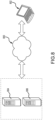
- FIG. 8 is an embodiment of a network 800 in which the various systems and methods disclosed herein may operate.
- a client device such as client device 802 may communicate with one or more servers, such as servers 804 and 806, via a network 800.
- a client device may be a standalone imaging system (e.g., imaging system 100 depicted in FIG. 1A ) that includes all the functionality described herein.
- the client device may also include or incorporate a laptop, a personal computer, a smart phone, a PDA, a netbook, or any other type of computing device, such as the computing device in FIG. 7 .
- such a client device may be connected to an imaging system.
- servers 804 and 806 may also be any type of computing device, such as the computing device illustrated in FIG. 7 .
- Network 800 may be any type of network capable of facilitating communications between the client device and one or more servers 804 and 806.
- the surface image data and the internal image data may be acquired locally via the imaging systems and communicated to another computing device(s) for further processing, such as an image acquisition workstation or a cloud-based service.
- Examples of such networks include, but are not limited to, LANs, WANs, cellular networks, and/or the Internet.
- the various systems and methods disclosed herein may be performed by one or more server devices.
- a single server such as server 804 may be employed to perform the systems and methods disclosed herein, such as the methods for imaging discussed herein.
- Client device 802 may interact with server 804 via network 800.
- the client device 802 may also perform functionality disclosed herein, such as scanning and image processing, which can then be provided to servers 804 and/or 806.
Landscapes
- Health & Medical Sciences (AREA)
- Life Sciences & Earth Sciences (AREA)
- Engineering & Computer Science (AREA)
- Medical Informatics (AREA)
- Physics & Mathematics (AREA)
- Heart & Thoracic Surgery (AREA)
- Surgery (AREA)
- Nuclear Medicine, Radiotherapy & Molecular Imaging (AREA)
- Veterinary Medicine (AREA)
- Pathology (AREA)
- Radiology & Medical Imaging (AREA)
- Biomedical Technology (AREA)
- Biophysics (AREA)
- Molecular Biology (AREA)
- Public Health (AREA)
- Animal Behavior & Ethology (AREA)
- General Health & Medical Sciences (AREA)
- High Energy & Nuclear Physics (AREA)
- Optics & Photonics (AREA)
- Dentistry (AREA)
- Oral & Maxillofacial Surgery (AREA)
- General Physics & Mathematics (AREA)
- Theoretical Computer Science (AREA)
- Apparatus For Radiation Diagnosis (AREA)
Claims (15)
- Verfahren für eine Verstärkungskalibrierung bei einer Vielzahl von Bildgebungsparametern für eine Tomosyntheseabtastung, das Verfahren umfassend:Durchführen (502,602) einer oder mehrerer Tomosyntheseabtastungen, um eine Vielzahl von Tomosyntheseprojektionsröntgenbildern zu erfassen, wobei jedes der Vielzahl von Tomosyntheseprojektionsröntgenbildern mit einem der Vielzahl von Bildgebungsparametern verknüpft ist;Erzeugen (504) eines Hochdosisröntgenbilds durch Mitteln der Vielzahl von Tomosyntheseproj ektionsröntgenbildern;Erzeugen (506) einer Hochdosisverstärkungskarte, die mit dem Hochdosisröntgenbild verknüpft ist;Erzeugen (510) einer Vielzahl von Niedrigdosisverstärkungskarten, wobei jede der Vielzahl von Niedrigdosisverstärkungskarten mit einem der Vielzahl von Tomosyntheseprojektionsröntgenbildern verknüpft ist, die mit einem der Vielzahl von Bildgebungsparametern verknüpft ist;Zerlegen jeder der Vielzahl von Niedrigdosisverstärkungskarten in eine Vielzahl von Komponentenstufen;Extrahieren (512) von Komponenten mit niedriger Auflösung aus der Vielzahl von Komponentenstufen für jede der Vielzahl von Niedrigdosisverstärkungskarten; undfür jeden der Vielzahl von Bildgebungsparametern, Kombinieren (514) der Hochdosisverstärkungskarte mit jeder der Komponenten mit niedriger Auflösung der Niedrigdosisverstärkungskarten, um eine endgültige Verstärkungskarte für jeden der Vielzahl von Bildgebungsparametern zu erzeugen.
- Verfahren nach Anspruch 1, ferner umfassend:Speichern der endgültigen Verstärkungskarte für jeden der Vielzahl von Bildgebungsparametern;Aufnehmen von Tomosyntheseröntgenbildern einer Brust eines Patienten bei jedem der Vielzahl von Bildgebungsparametern; undVerstärkungskorregieren der Tomosyntheseröntgenbilder der Brust des Patienten unter Verwendung der gespeicherten endgültigen Verstärkungskarte für jeden der Vielzahl von Bildgebungsparametern, um verstärkungskorrigierte Brustbilder zu produzieren.
- Verfahren nach einem der Ansprüche 1 bis 2, wobei die Bildgebungsparameter eines einschließen von: Projektionswinkel, kVp, Filtermaterialtyp, Brustdicke und Gitterposition.
- Verfahren nach einem der Ansprüche 1 bis 3, wobei die eine oder die mehreren Tomosyntheseabtastungen durch eine Bilderfassungseinheit durchgeführt werden, umfassend eine Röntgenquelle und einen Röntgenbildempfänger, wobei die Bilderfassungseinheit Projektionsröntgenbilder eines Objekts bei der Vielzahl von Bildgebungsparametern erfasst.
- Verfahren nach einem der Ansprüche 1 bis 4, wobei das Erzeugen der Hochdosisverstärkungskarte umfasst:Bestimmen einer mittleren Signalanzahl für eine Pixelanordnung, die mit dem Hochdosisröntgenbild verknüpft ist;Bestimmen einer Rohsignalanzahl für jedes der Pixel aus der Pixelanordnung, die mit dem Hochdosisröntgenbild verknüpft ist;Berechnen des Verstärkungskorrekturkoeffizienten für jedes der Pixel in der Pixelanordnung, die mit dem Hochdosisröntgenbild verknüpft ist, wobei der Verstärkungskorrekturkoeffizient ein Produkt aus der mittleren Signalanzahl und einem Kehrwert der Rohsignalanzahl für das festgelegte Pixel ist; undZusammensetzen des Verstärkungskorrekturkoeffizienten für jedes der Pixel in der Pixelanordnung in der Hochdosisverstärkungskarte.
- Verfahren nach einem der Ansprüche 1 bis 5, wobei das Zerlegen jeder der Vielzahl von Niedrigdosisverstärkungskarten das Zerlegen in eine Vielzahl von Auflösungsstufen einschließt, wobei jede Stufe der Vielzahl von Auflösungsstufen ein Detailbild und ein Restbild einschließt, vorzugsweise wobei das Zerlegen jeder der Vielzahl von Niedrigdosisverstärkungskarten unter Verwendung eines mehrskaligen Zerlegungsprozesses durchgeführt wird, mehr bevorzugt wobei das Extrahieren der Komponenten mit niedriger Auflösung das Extrahieren der Komponenten mit niedriger Auflösung aus dem Restbild einer letzten Stufe der Vielzahl von Auflösungsstufen einschließt.
- Verfahren nach einem der Ansprüche 1 bis 6, wobei die Hochdosisverstärkungskarte Daten für eine Verstärkungsvariation des Röntgendetektors von Pixel zu Pixel umfasst.
- Verfahren nach einem der Ansprüche 1 bis 7, wobei die Komponenten mit niedriger Auflösung eines umfassen von: Winkeldaten, kV-Daten, Filterdaten, Gitterdaten und Dickendaten.
- Tomosynthesebildgebungssystem (100) für die Verstärkungskalibrierung bei einer Vielzahl von Projektionswinkeln, das System umfassend:eine Bilderfassungseinheit (204), umfassend eine Röntgenquelle (122) und einen Röntgenbildempfänger (116), wobei die Bilderfassungseinheit Projektionsröntgenbilder eines Objekts bei der Vielzahl von Projektionswinkeln erfasst;einen Prozessor;Speicher, der Anweisungen einschließt, die, wenn sie durch den Prozessor ausgeführt werden, den Prozessorveranlassen zum:- Durchführen (502, 602) einer oder mehrerer Tomosyntheseabtastungen, um eine Vielzahl von Tomosyntheseprojektionsröntgenbildern zu erfassen, wobei jedes der Vielzahl von Tomosyntheseprojektionsröntgenbildern einem der Vielzahl von Projektionswinkeln zugeordnet ist;- Erzeugen (504) eines Hochdosisröntgenbilds durch Mitteln der Vielzahl von Tomosyntheseproj ektionsröntgenbildem;- Erzeugen (506) einer Hochdosisverstärkungskarte, die mit dem Hochdosisröntgenbild verknüpft ist;- Zerlegen der Hochdosisverstärkungskarte in eine erste Vielzahl von Komponentenstufen;- Extrahieren (508) einer Komponente mit hoher Auflösung aus der ersten Vielzahl von Komponentenstufen;- Erzeugen (510) einer Vielzahl von Niedrigdosisverstärkungskarten, wobei jede der Vielzahl von Niedrigdosisverstärkungskarten mit einem der Vielzahl von Tomosyntheseprojektionsröntgenbildern verknüpft ist, die mit einem der Vielzahl von Projektionswinkeln verknüpft ist;- Zerlegen jeder der Vielzahl von Niedrigdosisverstärkungskarten in eine zweite Vielzahl von Komponentenstufen;- Extrahieren (512) von Komponenten mit niedriger Auflösung aus j eder der Vielzahl von Niedrigdosisverstärkungskarten, wobei die Komponenten mit niedriger Auflösung eine Winkelkarte umfassen; und- für jeden der Vielzahl von Projektionswinkeln, Kombinieren (514) der Komponente mit hoher Auflösung der Hochdosisverstärkungskarte mit jeder der Komponenten mit niedriger Auflösung der Niedrigdosisverstärkungskarten, um eine endgültige Verstärkungskarte für jeden der Vielzahl von Proj ektionswinkeln zu erzeugen.
- System nach Anspruch 9, wobei die Anweisungen, wenn sie durch den Prozessor ausgeführt werden, den Prozessor ferner veranlassen zum:Speichern der endgültigen Verstärkungskarte für jeden der Vielzahl von Proj ektionswinkeln;Erfassen der Tomosyntheseröntgenbilder einer Brust des Patienten aus jedem der Vielzahl von Projektionswinkeln; undVerstärkungskorrigieren der Tomosyntheseröntgenbilder der Brust des Patienten unter Verwendung der gespeicherten endgültigen Verstärkungskarte für jeden der Vielzahl von Projektionswinkeln, um verstärkungskorrigierte Brustbilder zu produzieren.
- System nach einem der Ansprüche 9 bis 10, wobei die eine oder die mehreren Tomosyntheseabtastungen durchgeführt werden, um eine Vielzahl von Tomosyntheseprojektionsröntgenbildern eines Phantoms zu erfassen.
- System nach einem der Ansprüche 9 bis 11, wobei die Anweisungen, wenn sie durch den Prozessor ausgeführt werden, um die Hochdosisverstärkungskarte zu erzeugen, den Prozessor veranlassen zum:Bestimmen einer mittleren Signalanzahl für eine Pixelanordnung, die mit dem Hochdosisröntgenbild verknüpft ist;Bestimmen einer Rohsignalanzahl für jedes der Pixel aus der Pixelanordnung, die mit dem Hochdosisröntgenbild verknüpft ist;Berechnen des Verstärkungskorrekturkoeffizienten für jedes der Pixel in der Pixelanordnung, die mit dem Hochdosisröntgenbild verknüpft ist, wobei der Verstärkungskorrekturkoeffizient ein Produkt aus der mittleren Signalanzahl und einem Kehrwert der Rohsignalanzahl für das festgelegte Pixel ist; undZusammenfügen des Verstärkungskorrekturkoeffizienten für jedes der Pixel in der Pixelanordnung für die Hochdosisverstärkungskarte.
- System nach einem der Ansprüche 9 bis 12, wobei das Zerlegen der Hochdosisverstärkungskarte und das Zerlegen jeder der Vielzahl von Niedrigdosisverstärkungskarten das Zerlegen in eine Vielzahl von Auflösungsstufen einschließt, wobei jede Stufe der Vielzahl von Auflösungsstufen ein Detailbild und ein Restbild einschließt, vorzugsweise wobei das Zerlegen der Hochdosisverstärkungskarte und das Zerlegen jeder der Vielzahl von Niedrigdosisverstärkungskarten unter Verwendung eines mehrskaligen Zerlegungsprozesses durchgeführt wird, mehr bevorzugt wobei das Extrahieren der Komponente mit hoher Auflösung das Extrahieren einer Komponente mit hoher Auflösung aus dem Detailbild einer Stufe über einer letzten Stufe der Vielzahl von Auflösungsstufen einschließt und das Extrahieren der Komponenten mit niedriger Auflösung das Extrahieren von Komponenten mit niedriger Auflösung aus dem Restbild einer letzten Stufe der Vielzahl von Auflösungsstufen einschließt.
- System nach einem der Ansprüche 9 bis 13, wobei die Komponente mit hoher Auflösung Daten für die Verstärkungsvariation des Röntgendetektors von Pixel zu Pixel umfasst.
- System nach einem der Ansprüche 9 bis 14, wobei die Komponenten mit niedriger Auflösung ferner Winkeldaten, kV-Daten, Filterdaten, Gitterdaten und Dickendaten umfassen.
Applications Claiming Priority (2)
| Application Number | Priority Date | Filing Date | Title |
|---|---|---|---|
| US202163247503P | 2021-09-23 | 2021-09-23 | |
| PCT/US2022/076831 WO2023049782A1 (en) | 2021-09-23 | 2022-09-22 | Tomosynthesis gain calibration and image correction |
Publications (2)
| Publication Number | Publication Date |
|---|---|
| EP4404844A1 EP4404844A1 (de) | 2024-07-31 |
| EP4404844B1 true EP4404844B1 (de) | 2025-01-15 |
Family
ID=83995550
Family Applications (1)
| Application Number | Title | Priority Date | Filing Date |
|---|---|---|---|
| EP22794000.4A Active EP4404844B1 (de) | 2021-09-23 | 2022-09-22 | Tomosyntheseverstärkungskalibrierung und bildkorrektur |
Country Status (8)
| Country | Link |
|---|---|
| US (2) | US12159375B2 (de) |
| EP (1) | EP4404844B1 (de) |
| JP (1) | JP7597982B2 (de) |
| KR (1) | KR102800643B1 (de) |
| CN (1) | CN117999032A (de) |
| AU (1) | AU2022349635B2 (de) |
| ES (1) | ES3019532T3 (de) |
| WO (1) | WO2023049782A1 (de) |
Families Citing this family (2)
| Publication number | Priority date | Publication date | Assignee | Title |
|---|---|---|---|---|
| EP4217765A1 (de) | 2020-09-25 | 2023-08-02 | Hologic, Inc. | Photonenflussmodulation zur verbesserung des dynamikbereichs in photonenzähldetektoren |
| KR102790748B1 (ko) * | 2024-10-25 | 2025-04-07 | 테크밸리 주식회사 | Ct 영상품질 개선방법 및 이를 위한 시스템 |
Family Cites Families (14)
| Publication number | Priority date | Publication date | Assignee | Title |
|---|---|---|---|---|
| US7212604B2 (en) | 2005-06-29 | 2007-05-01 | General Electric Company | Multi-layer direct conversion computed tomography detector module |
| US7949174B2 (en) | 2006-10-19 | 2011-05-24 | General Electric Company | System and method for calibrating an X-ray detector |
| JP2009011639A (ja) | 2007-07-06 | 2009-01-22 | Konica Minolta Holdings Inc | 情報処理装置、およびプログラム |
| JP2009171990A (ja) | 2007-08-16 | 2009-08-06 | General Electric Co <Ge> | X線検出器を較正するシステム及び方法 |
| US7991106B2 (en) | 2008-08-29 | 2011-08-02 | Hologic, Inc. | Multi-mode tomosynthesis/mammography gain calibration and image correction using gain map information from selected projection angles |
| US20130156163A1 (en) | 2011-12-19 | 2013-06-20 | General Electric Company | Method and apparatus for reconstructing an image of an object |
| RU2014143053A (ru) | 2012-03-27 | 2016-05-20 | Конинклейке Филипс Н.В. | Обычная визуализация посредством системы визуализации, содержащей детекторы для счета фотонов |
| JP6141995B2 (ja) | 2013-09-27 | 2017-06-07 | 富士フイルム株式会社 | マンモグラフィ装置、放射線画像撮影方法およびプログラム |
| JP6437345B2 (ja) | 2015-02-25 | 2018-12-12 | キヤノンメディカルシステムズ株式会社 | 光子計数型x線検出器及び光子計数型x線ct装置 |
| AU2016222642B2 (en) | 2015-02-26 | 2021-07-15 | Hologic, Inc. | Methods for physiological state determination in body scans |
| KR20170088681A (ko) * | 2016-01-25 | 2017-08-02 | 삼성전자주식회사 | 단층 촬영 장치 및 그에 따른 단층 영상 복원 방법 |
| US9851460B1 (en) | 2016-09-07 | 2017-12-26 | Toshiba Medical Systmes Corporation | Apparatus and method for a high-flux photon-counting spectral application-specific integrated circuit (ASIC) having a charge summing mode |
| US11147522B2 (en) | 2018-08-31 | 2021-10-19 | Canon Medical Systems Corporation | Photon counting detector and x-ray computed tomography apparatus |
| EP4217765A1 (de) | 2020-09-25 | 2023-08-02 | Hologic, Inc. | Photonenflussmodulation zur verbesserung des dynamikbereichs in photonenzähldetektoren |
-
2022
- 2022-09-22 KR KR1020247009285A patent/KR102800643B1/ko active Active
- 2022-09-22 WO PCT/US2022/076831 patent/WO2023049782A1/en not_active Ceased
- 2022-09-22 JP JP2024518150A patent/JP7597982B2/ja active Active
- 2022-09-22 US US18/692,989 patent/US12159375B2/en active Active
- 2022-09-22 AU AU2022349635A patent/AU2022349635B2/en active Active
- 2022-09-22 ES ES22794000T patent/ES3019532T3/es active Active
- 2022-09-22 EP EP22794000.4A patent/EP4404844B1/de active Active
- 2022-09-22 CN CN202280064262.7A patent/CN117999032A/zh active Pending
-
2024
- 2024-10-28 US US18/928,531 patent/US20250157001A1/en active Pending
Also Published As
| Publication number | Publication date |
|---|---|
| AU2022349635B2 (en) | 2025-01-09 |
| CN117999032A (zh) | 2024-05-07 |
| KR102800643B1 (ko) | 2025-04-28 |
| WO2023049782A1 (en) | 2023-03-30 |
| ES3019532T3 (en) | 2025-05-20 |
| KR20240042194A (ko) | 2024-04-01 |
| AU2022349635A1 (en) | 2024-03-21 |
| JP7597982B2 (ja) | 2024-12-10 |
| JP2024534548A (ja) | 2024-09-20 |
| EP4404844A1 (de) | 2024-07-31 |
| US20240331101A1 (en) | 2024-10-03 |
| US20250157001A1 (en) | 2025-05-15 |
| US12159375B2 (en) | 2024-12-03 |
Similar Documents
| Publication | Publication Date | Title |
|---|---|---|
| US20250157001A1 (en) | Tomosynthesis gain calibration and image correction | |
| US10602998B2 (en) | Methods and systems for dynamically modifying acquisition parameter during image acquisition | |
| US9636079B2 (en) | Motion layer decomposition calibration of x-ray CT imagers | |
| US6980624B2 (en) | Non-uniform view weighting tomosynthesis method and apparatus | |
| US9613440B2 (en) | Digital breast Tomosynthesis reconstruction using adaptive voxel grid | |
| JP2024094379A (ja) | 湾曲した圧迫要素を用いた撮像 | |
| US8411923B2 (en) | Tomographic image reconstruction method and apparatus using filtered back projection | |
| US20050123215A1 (en) | Method and apparatus for the reduction of artifacts in computed tomography images | |
| US10825210B2 (en) | Method and apparatus for projection domain truncation correction in computed-tomography (CT) | |
| US20070133747A1 (en) | System and method for imaging using distributed X-ray sources | |
| JP2021102050A (ja) | 焦点の動き検出および補正のためのシステムおよび方法 | |
| US20260020827A1 (en) | Wide angle automatic exposure control in tomosynthesis | |
| JP7309381B2 (ja) | 医用画像診断装置および医用寝台装置 |
Legal Events
| Date | Code | Title | Description |
|---|---|---|---|
| STAA | Information on the status of an ep patent application or granted ep patent |
Free format text: STATUS: UNKNOWN |
|
| STAA | Information on the status of an ep patent application or granted ep patent |
Free format text: STATUS: THE INTERNATIONAL PUBLICATION HAS BEEN MADE |
|
| PUAI | Public reference made under article 153(3) epc to a published international application that has entered the european phase |
Free format text: ORIGINAL CODE: 0009012 |
|
| STAA | Information on the status of an ep patent application or granted ep patent |
Free format text: STATUS: REQUEST FOR EXAMINATION WAS MADE |
|
| 17P | Request for examination filed |
Effective date: 20240419 |
|
| AK | Designated contracting states |
Kind code of ref document: A1 Designated state(s): AL AT BE BG CH CY CZ DE DK EE ES FI FR GB GR HR HU IE IS IT LI LT LU LV MC MK MT NL NO PL PT RO RS SE SI SK SM TR |
|
| GRAP | Despatch of communication of intention to grant a patent |
Free format text: ORIGINAL CODE: EPIDOSNIGR1 |
|
| STAA | Information on the status of an ep patent application or granted ep patent |
Free format text: STATUS: GRANT OF PATENT IS INTENDED |
|
| DAV | Request for validation of the european patent (deleted) | ||
| DAX | Request for extension of the european patent (deleted) | ||
| INTG | Intention to grant announced |
Effective date: 20240916 |
|
| GRAS | Grant fee paid |
Free format text: ORIGINAL CODE: EPIDOSNIGR3 |
|
| GRAA | (expected) grant |
Free format text: ORIGINAL CODE: 0009210 |
|
| STAA | Information on the status of an ep patent application or granted ep patent |
Free format text: STATUS: THE PATENT HAS BEEN GRANTED |
|
| P01 | Opt-out of the competence of the unified patent court (upc) registered |
Free format text: CASE NUMBER: APP_63667/2024 Effective date: 20241129 |
|
| AK | Designated contracting states |
Kind code of ref document: B1 Designated state(s): AL AT BE BG CH CY CZ DE DK EE ES FI FR GB GR HR HU IE IS IT LI LT LU LV MC MK MT NL NO PL PT RO RS SE SI SK SM TR |
|
| REG | Reference to a national code |
Ref country code: CH Ref legal event code: EP Ref country code: GB Ref legal event code: FG4D |
|
| REG | Reference to a national code |
Ref country code: DE Ref legal event code: R096 Ref document number: 602022009652 Country of ref document: DE |
|
| REG | Reference to a national code |
Ref country code: IE Ref legal event code: FG4D |
|
| REG | Reference to a national code |
Ref country code: NL Ref legal event code: FP |
|
| REG | Reference to a national code |
Ref country code: ES Ref legal event code: FG2A Ref document number: 3019532 Country of ref document: ES Kind code of ref document: T3 Effective date: 20250520 |
|
| PG25 | Lapsed in a contracting state [announced via postgrant information from national office to epo] |
Ref country code: RS Free format text: LAPSE BECAUSE OF FAILURE TO SUBMIT A TRANSLATION OF THE DESCRIPTION OR TO PAY THE FEE WITHIN THE PRESCRIBED TIME-LIMIT Effective date: 20250415 |
|
| PG25 | Lapsed in a contracting state [announced via postgrant information from national office to epo] |
Ref country code: FI Free format text: LAPSE BECAUSE OF FAILURE TO SUBMIT A TRANSLATION OF THE DESCRIPTION OR TO PAY THE FEE WITHIN THE PRESCRIBED TIME-LIMIT Effective date: 20250115 |
|
| PG25 | Lapsed in a contracting state [announced via postgrant information from national office to epo] |
Ref country code: PL Free format text: LAPSE BECAUSE OF FAILURE TO SUBMIT A TRANSLATION OF THE DESCRIPTION OR TO PAY THE FEE WITHIN THE PRESCRIBED TIME-LIMIT Effective date: 20250115 |
|
| REG | Reference to a national code |
Ref country code: LT Ref legal event code: MG9D |
|
| PG25 | Lapsed in a contracting state [announced via postgrant information from national office to epo] |
Ref country code: IS Free format text: LAPSE BECAUSE OF FAILURE TO SUBMIT A TRANSLATION OF THE DESCRIPTION OR TO PAY THE FEE WITHIN THE PRESCRIBED TIME-LIMIT Effective date: 20250515 Ref country code: NO Free format text: LAPSE BECAUSE OF FAILURE TO SUBMIT A TRANSLATION OF THE DESCRIPTION OR TO PAY THE FEE WITHIN THE PRESCRIBED TIME-LIMIT Effective date: 20250415 |
|
| REG | Reference to a national code |
Ref country code: AT Ref legal event code: MK05 Ref document number: 1759301 Country of ref document: AT Kind code of ref document: T Effective date: 20250115 |
|
| PG25 | Lapsed in a contracting state [announced via postgrant information from national office to epo] |
Ref country code: HR Free format text: LAPSE BECAUSE OF FAILURE TO SUBMIT A TRANSLATION OF THE DESCRIPTION OR TO PAY THE FEE WITHIN THE PRESCRIBED TIME-LIMIT Effective date: 20250115 |
|
| PG25 | Lapsed in a contracting state [announced via postgrant information from national office to epo] |
Ref country code: LV Free format text: LAPSE BECAUSE OF FAILURE TO SUBMIT A TRANSLATION OF THE DESCRIPTION OR TO PAY THE FEE WITHIN THE PRESCRIBED TIME-LIMIT Effective date: 20250115 Ref country code: PT Free format text: LAPSE BECAUSE OF FAILURE TO SUBMIT A TRANSLATION OF THE DESCRIPTION OR TO PAY THE FEE WITHIN THE PRESCRIBED TIME-LIMIT Effective date: 20250515 |
|
| PG25 | Lapsed in a contracting state [announced via postgrant information from national office to epo] |
Ref country code: BG Free format text: LAPSE BECAUSE OF FAILURE TO SUBMIT A TRANSLATION OF THE DESCRIPTION OR TO PAY THE FEE WITHIN THE PRESCRIBED TIME-LIMIT Effective date: 20250115 Ref country code: GR Free format text: LAPSE BECAUSE OF FAILURE TO SUBMIT A TRANSLATION OF THE DESCRIPTION OR TO PAY THE FEE WITHIN THE PRESCRIBED TIME-LIMIT Effective date: 20250416 |
|
| PG25 | Lapsed in a contracting state [announced via postgrant information from national office to epo] |
Ref country code: AT Free format text: LAPSE BECAUSE OF FAILURE TO SUBMIT A TRANSLATION OF THE DESCRIPTION OR TO PAY THE FEE WITHIN THE PRESCRIBED TIME-LIMIT Effective date: 20250115 |
|
| PG25 | Lapsed in a contracting state [announced via postgrant information from national office to epo] |
Ref country code: SE Free format text: LAPSE BECAUSE OF FAILURE TO SUBMIT A TRANSLATION OF THE DESCRIPTION OR TO PAY THE FEE WITHIN THE PRESCRIBED TIME-LIMIT Effective date: 20250115 |
|
| PG25 | Lapsed in a contracting state [announced via postgrant information from national office to epo] |
Ref country code: SM Free format text: LAPSE BECAUSE OF FAILURE TO SUBMIT A TRANSLATION OF THE DESCRIPTION OR TO PAY THE FEE WITHIN THE PRESCRIBED TIME-LIMIT Effective date: 20250115 |
|
| PG25 | Lapsed in a contracting state [announced via postgrant information from national office to epo] |
Ref country code: DK Free format text: LAPSE BECAUSE OF FAILURE TO SUBMIT A TRANSLATION OF THE DESCRIPTION OR TO PAY THE FEE WITHIN THE PRESCRIBED TIME-LIMIT Effective date: 20250115 |
|
| PGFP | Annual fee paid to national office [announced via postgrant information from national office to epo] |
Ref country code: DE Payment date: 20250929 Year of fee payment: 4 |
|
| PGFP | Annual fee paid to national office [announced via postgrant information from national office to epo] |
Ref country code: NL Payment date: 20250926 Year of fee payment: 4 |
|
| REG | Reference to a national code |
Ref country code: DE Ref legal event code: R097 Ref document number: 602022009652 Country of ref document: DE |
|
| PGFP | Annual fee paid to national office [announced via postgrant information from national office to epo] |
Ref country code: FR Payment date: 20250925 Year of fee payment: 4 |
|
| PG25 | Lapsed in a contracting state [announced via postgrant information from national office to epo] |
Ref country code: EE Free format text: LAPSE BECAUSE OF FAILURE TO SUBMIT A TRANSLATION OF THE DESCRIPTION OR TO PAY THE FEE WITHIN THE PRESCRIBED TIME-LIMIT Effective date: 20250115 Ref country code: CZ Free format text: LAPSE BECAUSE OF FAILURE TO SUBMIT A TRANSLATION OF THE DESCRIPTION OR TO PAY THE FEE WITHIN THE PRESCRIBED TIME-LIMIT Effective date: 20250115 |
|
| PG25 | Lapsed in a contracting state [announced via postgrant information from national office to epo] |
Ref country code: RO Free format text: LAPSE BECAUSE OF FAILURE TO SUBMIT A TRANSLATION OF THE DESCRIPTION OR TO PAY THE FEE WITHIN THE PRESCRIBED TIME-LIMIT Effective date: 20250115 |
|
| PG25 | Lapsed in a contracting state [announced via postgrant information from national office to epo] |
Ref country code: SK Free format text: LAPSE BECAUSE OF FAILURE TO SUBMIT A TRANSLATION OF THE DESCRIPTION OR TO PAY THE FEE WITHIN THE PRESCRIBED TIME-LIMIT Effective date: 20250115 |
|
| PLBE | No opposition filed within time limit |
Free format text: ORIGINAL CODE: 0009261 |
|
| STAA | Information on the status of an ep patent application or granted ep patent |
Free format text: STATUS: NO OPPOSITION FILED WITHIN TIME LIMIT |
|
| 26N | No opposition filed |
Effective date: 20251016 |
|
| PGFP | Annual fee paid to national office [announced via postgrant information from national office to epo] |
Ref country code: IT Payment date: 20250930 Year of fee payment: 4 |
|
| PGFP | Annual fee paid to national office [announced via postgrant information from national office to epo] |
Ref country code: ES Payment date: 20251001 Year of fee payment: 4 |