EP4404603A1 - Kommunikationsverfahren, -vorrichtung und -system - Google Patents
Kommunikationsverfahren, -vorrichtung und -system Download PDFInfo
- Publication number
- EP4404603A1 EP4404603A1 EP22882774.7A EP22882774A EP4404603A1 EP 4404603 A1 EP4404603 A1 EP 4404603A1 EP 22882774 A EP22882774 A EP 22882774A EP 4404603 A1 EP4404603 A1 EP 4404603A1
- Authority
- EP
- European Patent Office
- Prior art keywords
- node
- information
- pdu session
- identifier
- mapping relationship
- Prior art date
- Legal status (The legal status is an assumption and is not a legal conclusion. Google has not performed a legal analysis and makes no representation as to the accuracy of the status listed.)
- Pending
Links
Images


Classifications
-
- H—ELECTRICITY
- H04—ELECTRIC COMMUNICATION TECHNIQUE
- H04W—WIRELESS COMMUNICATION NETWORKS
- H04W8/00—Network data management
- H04W8/18—Processing of user or subscriber data, e.g. subscribed services, user preferences or user profiles; Transfer of user or subscriber data
- H04W8/20—Transfer of user or subscriber data
-
- H—ELECTRICITY
- H04—ELECTRIC COMMUNICATION TECHNIQUE
- H04L—TRANSMISSION OF DIGITAL INFORMATION, e.g. TELEGRAPHIC COMMUNICATION
- H04L47/00—Traffic control in data switching networks
- H04L47/10—Flow control; Congestion control
- H04L47/24—Traffic characterised by specific attributes, e.g. priority or QoS
- H04L47/2483—Traffic characterised by specific attributes, e.g. priority or QoS involving identification of individual flows
-
- H—ELECTRICITY
- H04—ELECTRIC COMMUNICATION TECHNIQUE
- H04L—TRANSMISSION OF DIGITAL INFORMATION, e.g. TELEGRAPHIC COMMUNICATION
- H04L61/00—Network arrangements, protocols or services for addressing or naming
- H04L61/09—Mapping addresses
- H04L61/25—Mapping addresses of the same type
- H04L61/2503—Translation of Internet protocol [IP] addresses
- H04L61/2517—Translation of Internet protocol [IP] addresses using port numbers
-
- H—ELECTRICITY
- H04—ELECTRIC COMMUNICATION TECHNIQUE
- H04L—TRANSMISSION OF DIGITAL INFORMATION, e.g. TELEGRAPHIC COMMUNICATION
- H04L67/00—Network arrangements or protocols for supporting network services or applications
- H04L67/14—Session management
- H04L67/141—Setup of application sessions
-
- H—ELECTRICITY
- H04—ELECTRIC COMMUNICATION TECHNIQUE
- H04L—TRANSMISSION OF DIGITAL INFORMATION, e.g. TELEGRAPHIC COMMUNICATION
- H04L67/00—Network arrangements or protocols for supporting network services or applications
- H04L67/14—Session management
- H04L67/146—Markers for unambiguous identification of a particular session, e.g. session cookie or URL-encoding
-
- H—ELECTRICITY
- H04—ELECTRIC COMMUNICATION TECHNIQUE
- H04L—TRANSMISSION OF DIGITAL INFORMATION, e.g. TELEGRAPHIC COMMUNICATION
- H04L69/00—Network arrangements, protocols or services independent of the application payload and not provided for in the other groups of this subclass
- H04L69/08—Protocols for interworking; Protocol conversion
- H04L69/085—Protocols for interworking; Protocol conversion specially adapted for interworking of IP-based networks with other networks
-
- H—ELECTRICITY
- H04—ELECTRIC COMMUNICATION TECHNIQUE
- H04L—TRANSMISSION OF DIGITAL INFORMATION, e.g. TELEGRAPHIC COMMUNICATION
- H04L2101/00—Indexing scheme associated with group H04L61/00
- H04L2101/60—Types of network addresses
- H04L2101/618—Details of network addresses
- H04L2101/622—Layer-2 addresses, e.g. medium access control [MAC] addresses
-
- Y—GENERAL TAGGING OF NEW TECHNOLOGICAL DEVELOPMENTS; GENERAL TAGGING OF CROSS-SECTIONAL TECHNOLOGIES SPANNING OVER SEVERAL SECTIONS OF THE IPC; TECHNICAL SUBJECTS COVERED BY FORMER USPC CROSS-REFERENCE ART COLLECTIONS [XRACs] AND DIGESTS
- Y02—TECHNOLOGIES OR APPLICATIONS FOR MITIGATION OR ADAPTATION AGAINST CLIMATE CHANGE
- Y02D—CLIMATE CHANGE MITIGATION TECHNOLOGIES IN INFORMATION AND COMMUNICATION TECHNOLOGIES [ICT], I.E. INFORMATION AND COMMUNICATION TECHNOLOGIES AIMING AT THE REDUCTION OF THEIR OWN ENERGY USE
- Y02D30/00—Reducing energy consumption in communication networks
- Y02D30/70—Reducing energy consumption in communication networks in wireless communication networks
Definitions
- Embodiments of this application relate to the field of communication technologies, and in particular, to a communication method, apparatus, and system.
- a 5th generation (5th generation, 5G) cellular network communication system may provide macro coverage, and a communication range is wide, but power consumption of the terminal and costs are relatively high. Based on this, the short-range communication system and the 5G cellular network communication system may be converged, so that the converged communication system can implement long-range transmission with low power consumption and low costs.
- a node for example, a management node
- PDU protocol data unit
- Embodiments of this application provide a communication method, apparatus, and system, so that a 5G core network perceives a terminal device that does not support NAS signaling transmission, and manages the terminal device that does not support NAS signaling transmission.
- an embodiment of this application provides a communication method, which may be applied to a first node.
- the method includes: obtaining first information, where the first information indicates a mapping relationship between a second node and the first node; and sending the first information to a third node, where the first information identifies the second node associated with a protocol data unit PDU session.
- the first node may send the mapping relationship between the second node (that is, a terminal node that does not support NAS signaling transmission) and the first node to the third node (a core network), so that the core network may identify (that is, perceive or manage) the terminal node that does not support NAS signaling transmission, thereby managing a service provided by the terminal node that does not support NAS signaling transmission, to better meet a requirement of the terminal device that does not support NAS signaling transmission.
- the second node that is, a terminal node that does not support NAS signaling transmission
- the third node a core network
- the first information indicates a mapping relationship between a second node and the first node includes: The first information indicates a first mapping relationship between an identifier of the second node and a first IP address of the first node, or a second mapping relationship between an identifier of the second node and a first port number of the first node, or a third mapping relationship between an identifier of the second node and a first media access control MAC address of the first node, or a mapping relationship between an identifier of the second node and a first identifier of the first node.
- the first node is a management node of the second node, and the first node may be configured to manage or maintain information of the second node.
- the mapping relationship between the first node and the second node means that the first node establishes a mapping relationship based on information (for example, an identifier) of the second node managed by the first node and specific information of the first node, and sends the mapping relationship to the core network, so that the core network can perceive the first node and the information of the second node managed by the first node.
- a plurality of implementations of the mapping relationship between the first node and the second node are provided, so that the third node can flexibly identify the second node in a plurality of manners.
- the first IP address is one of a plurality of public IP addresses allocated to the first node in the PDU session.
- the first port number is one of a plurality of port numbers allocated to the first node in the PDU session.
- the first MAC address is one of a plurality of MAC addresses derived by the first node based on a unique MAC address of the first node.
- the first identifier may be one of a plurality of identifiers temporarily allocated by the first node. The first identifier is used to establish a mapping relationship with the identifier of the second node.
- the mapping relationship between the second node and the first node is the first mapping relationship between the identifier of the second node and the first IP address of the first node.
- the mapping relationship between the second node and the first node is the second mapping relationship between the identifier of the second node and the first port number of the first node.
- the first information is carried in a non-access stratum NAS message
- the NAS message is any one of NAS messages in a PDU session establishment procedure, a PDU session modification procedure, and a registration procedure.
- the NAS message may include but is not limited to any one of a registration request message, an access session request message, a PDU session establishment request message, and a PDU session modification request message.
- the first node may send the first information to the third node in a plurality of cases.
- the second node in the PDU session is associated with a packet filter, and the packet filter is used to determine a quality of service QoS flow corresponding to the second node in the PDU session.
- one PDU session is associated with one or more packet filters (also referred to as a packet filter set), the packet filter includes an IP address and a port number of the first node, and a mapping relationship is established between the second node and the IP address or the port number of the first node. Therefore, the packet filter associated with the PDU session may be associated with the second node.
- packet filters also referred to as a packet filter set
- the third node may identify the second node from the PUD session based on the IP address and the port number of the first node, or the MAC address of the first node, or the identifier of the first node, and the mapping relationship between the first node and the second node, which is included in the packet filter, so that the third node can adjust a QoS policy of the second node.
- that the first node obtains the first information may include: receiving access-side session request information or access-side session modification request information from the second node; determining that the second node is associated with the PDU session; and establishing the first mapping relationship based on the identifier of the second node and the first IP address associated with the PDU session; or establishing the second mapping relationship based on the identifier of the second node and the first port number associated with the PDU session; or establishing the third mapping relationship based on the identifier of the second node and the first MAC address; or establishing the mapping relationship between the identifier of the second node and the first identifier of the first node based on the identifier of the second node and the first identifier.
- the access-side session request information indicates that the second node requests the first node to allocate a PDU session
- the access-side session modification request information indicates that the second node requests the first node to modify a PDU session.
- the first node after receiving information related to the PDU session from the second node, the first node associates the corresponding PDU session with the second node, and the first node may establish the mapping relationship between the second node and the first node.
- the PDU session is allocated by the first node to the second node based on a requirement of the second node, but the PDU session is directly associated (established between the first node and the core network) with the first node. Therefore, the third node may determine, based on the mapping relationship, a correspondence between the PDU session or data in the PDU session and the second node, so as to identify the second node associated with the PDU session.
- the first node may further: receive second information from the second node, where the second information includes link status information and/or node status information; add the identifier of the second node to the second information, to obtain third information; and send the third information to the third node.
- the link status information includes at least one of a short-range measurement amount (short-range air interface status information) and a link status measurement amount between a short-range node and a 5G core network.
- the first node may add the identifier of the second node to the control information, and send the control information to the third node.
- the third node may identify, based on the first information, data (for example, the QoS flow) associated with the second node, so that the third node accordingly adjusts configuration information (a QoS flow-related parameter) of the second node.
- the first node may further: receive configuration information from the third node, where the configuration information includes at least one of running status management information, node parameter update information, a link status detection policy, and a QoS configuration policy of the second node; and send the configuration information to the second node.
- the configuration information includes at least one of running status management information, node parameter update information, a link status detection policy, and a QoS configuration policy of the second node.
- the first node may forward, to the second node, the configuration information formulated by the third node for the second node.
- the third node may configure the second node, so that a service provided by the third node for the second node better adapts to a requirement of the second node.
- the link status detection policy includes at least one of a measurement object, a reporting object, a reporting threshold, a reporting period, and an event parameter.
- the running status management information includes any one of a power-on state, a power-off state, and a sleep state of the second node.
- the node status update information includes update information corresponding to any one of version information, power information, hardware information, and software information of the second node.
- Anode status reporting policy includes at least one of a reporting object, a reporting period, and a reporting event.
- the first node may further: send a fourth mapping relationship between the identifier of the second node and an IP address of the second node to a fourth node.
- the first node sends the fourth mapping relationship between the identifier of the second node and the IP address of the second node to the fourth node, so that the fourth node may identify the second node, thereby providing a service for the second node.
- the first node communicates with the second node based on a first communication technology, and communicates with the third node based on a second communication technology.
- an embodiment of this application provides a communication method, which may be applied to a third node.
- the method includes: receiving first information, where the first information indicates a mapping relationship between a second node and a first node; and identifying, based on the first information, the second node associated with a protocol data unit PDU session.
- the third node may maintain or manage the mapping relationship between the second node (that is, a terminal node that does not support NAS signaling transmission) and the first node, and may identify (that is, perceive or manage) the terminal node that does not support NAS signaling transmission, thereby managing a service provided by the terminal node that does not support NAS signaling transmission, to better meet a requirement of the terminal device that does not support NAS signaling transmission.
- the first information indicates a mapping relationship between a second node and a first node includes: The first information indicates a first mapping relationship between an identifier of the second node and a first IP address of the first node, or a second mapping relationship between an identifier of the second node and a first port number of the first node, or a third mapping relationship between an identifier of the second node and a first media access control MAC address of the first node, or a mapping relationship between an identifier of the second node and a first identifier of the first node.
- the first IP address is one of a plurality of public IP addresses allocated to the first node in the PDU session.
- the first port number is one of a plurality of port numbers allocated to the first node in the PDU session.
- the PDU session includes one public IP address of the first node.
- the first MAC address is one of a plurality of MAC addresses derived by the first node based on a unique MAC address of the first node.
- the first identifier may be one of a plurality of identifiers temporarily allocated by the first node.
- the first information is carried in a non-access stratum NAS message
- the NAS message is any one of NAS messages in a PDU session establishment procedure, a PDU session modification procedure, and a registration procedure.
- the NAS message may include but is not limited to any one of a registration request message, an access session request message, a PDU session establishment request message, and a PDU session modification request message.
- the second node in the PDU session is associated with a packet filter
- the packet filter is used to determine a quality of service QoS flow corresponding to the second node in the PDU session
- the QoS flow is used to transmit data associated with the second node
- the identifying, based on the first information, the second node associated with a protocol data unit PDU session includes: identifying, based on the public IP address of the first node in the packet filter and the first mapping relationship, the second node associated with the PDU session; or identifying, based on the port number of the first node in the packet filter and the second mapping relationship, the second node associated with the PDU session; or identifying, based on the MAC address of the first node in the packet filter and the third mapping relationship, the second node associated with the PDU session; or, identifying, based on the identifier of the first node in the packet filter and the mapping relationship between the identifier of the second node and the first identifier of the first node, the second node associated with the PDU session.
- the third node may further: receive third information, where the third information includes the identifier of the second node, link status information, and/or node status information; and identify, based on the identifier of the second node and the first mapping relationship, the second node associated with the third information; or identify, based on the identifier of the second node and the second mapping relationship, the second node associated with the third information; or identify, based on the identifier of the second node and the third mapping relationship, the second node associated with the third information; or identify, based on the identifier of the second node and the mapping relationship between the identifier of the second node and the first identifier of the first node, the second node associated with the third information.
- the link status information includes at least one of a short-range measurement amount (short-range air interface status information) and a link status measurement amount between a short-range node and a 5G core network.
- the third node may further: determine configuration information based on the first information, where the configuration information includes at least one of running status management information, node parameter update information, a link status detection policy, and a QoS configuration policy of the second node; and send the configuration information to the first node.
- the third node may further: communicate with the first node based on a second communication technology; and provide, based on the second communication technology, a service for the second node that is based on a first communication technology.
- an embodiment of this application provides a communication method, which may be applied to a second node.
- the method includes: receiving configuration information from a first node, where the configuration information includes at least one of running status management information, node parameter update information, a link status detection policy, and a quality of service QoS configuration policy of the second node; and configuring the second node based on the configuration information.
- the second node receives the configuration information forwarded by the first node, and may perform corresponding configuration on the second node based on the configuration information.
- the link status detection policy includes at least one of a measurement object, a reporting object, a reporting threshold, a reporting period, and an event parameter.
- the running status management information includes any one of a power-on state, a power-off state, and a sleep state of the second node.
- the node status update information includes update information corresponding to any one of version information, power information, hardware information, and software information of the second node.
- Anode status reporting policy includes at least one of a reporting object, a reporting period, and a reporting event.
- the second node may further send access-side session request information or access-side session modification request information to the first node. It may be understood that the access-side session request information indicates that the second node requests the first node to allocate a PDU session, and the access-side session modification request information indicates that the second node requests the first node to modify a PDU session.
- the second node may further send second information to the first node.
- the second information includes link status information and/or node status information.
- the second node may further communicate with the first node based on a first communication technology, and obtain a service provided based on a second communication technology from the third node.
- an embodiment of this application provides a communication method, which may be applied to a fourth node.
- the method includes: receiving a fourth mapping relationship between an identifier of a second node and an IP address of the second node from a first node; and determining the second node based on the fourth mapping relationship and the IP address of the second node.
- the fourth node may determine the second node based on the IP address of the second node and the fourth mapping relationship between the identifier of the second node and the IP address of the second node, so that the fourth node may identify (that is, perceive or manage) the second node, thereby better providing a service for the second node.
- an embodiment of this application provides a communication apparatus.
- the apparatus is configured to implement the method in any one of the first aspect or any possible design of the first aspect, and includes corresponding functional modules or units, which are separately configured to implement steps in the method in the first aspect.
- a function may be implemented by hardware, or may be implemented by hardware by executing corresponding software.
- the hardware or software includes one or more modules corresponding to the function.
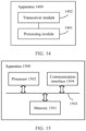
- the communication apparatus may include: a processing module, configured to obtain first information, where the first information indicates a mapping relationship between a second node and a first node; and a transceiver module, configured to send the first information to a third node, where the first information identifies the second node associated with a protocol data unit PDU session.
- a processing module configured to obtain first information, where the first information indicates a mapping relationship between a second node and a first node
- a transceiver module configured to send the first information to a third node, where the first information identifies the second node associated with a protocol data unit PDU session.
- the first information indicates a mapping relationship between a second node and a first node includes: The first information indicates a first mapping relationship between an identifier of the second node and a first IP address of the first node, or a second mapping relationship between an identifier of the second node and a first port number of the first node, or a third mapping relationship between an identifier of the second node and a first media access control MAC address of the first node, or a mapping relationship between an identifier of the second node and a first identifier of the first node.
- the first IP address is one of a plurality of public IP addresses allocated to the first node in the PDU session.
- the first port number is one of a plurality of port numbers allocated to the first node in the PDU session, and the PDU session includes one public IP address of the first node.
- the first identifier may be one of a plurality of identifiers temporarily allocated by the first node.
- the first information is carried in a non-access stratum NAS message
- the NAS message is any one of NAS messages in a PDU session establishment procedure, a PDU session modification procedure, and a registration procedure.
- the NAS message may include but is not limited to any one of a registration request message, an access session request message, a PDU session establishment request message, and a PDU session modification request message.
- the second node in the PDU session is associated with a packet filter, and the packet filter is used to determine a quality of service QoS flow corresponding to the second node in the PDU session.
- the transceiver module is further configured to receive access-side session request information or access-side session modification request information from the second node.
- the processing module is further configured to: determine that the second node is associated with the PDU session; and establish the first mapping relationship based on the identifier of the second node and the first IP address associated with the PDU session; or establish the second mapping relationship based on the identifier of the second node and the first port number associated with the PDU session; or establish the third mapping relationship based on the identifier of the second node and the first MAC address; or establish the mapping relationship between the identifier of the second node and the first identifier of the first node based on the identifier of the second node and the first identifier.
- the access-side session request information indicates that the second node requests the first node to allocate a PDU session
- the access-side session modification request information indicates that the second node requests the first node to modify a PDU session.
- the transceiver module may further receive second information from the second node.
- the second information includes link status information and/or node status information.
- the processing module may further add the identifier of the second node to the second information, to obtain third information.
- the transceiver module may send the third information to the third node.
- the link status information includes at least one of a short-range measurement amount (short-range air interface status information) and a link status measurement amount between a short-range node and a 5G core network.
- the transceiver module may further: receive configuration information from the third node, where the configuration information includes at least one of running status management information, node parameter update information, a link status detection policy, and a QoS configuration policy of the second node; and send the configuration information to the second node.
- the link status detection policy includes at least one of a measurement object, a reporting object, a reporting threshold, a reporting period, and an event parameter.
- the running status management information includes any one of a power-on state, a power-off state, and a sleep state of the second node.
- the node status update information includes update information corresponding to any one of version information, power information, hardware information, and software information of the second node.
- a node status reporting policy includes at least one of a reporting object, a reporting period, and a reporting event.
- the transceiver module may further send a fourth mapping relationship between the identifier of the second node and an IP address of the second node to a fourth node.
- the transceiver module may communicate with the second node based on a first communication technology, and communicate with the third node based on a second communication technology.
- an embodiment of this application provides a communication apparatus.
- the apparatus is configured to implement any one of the second aspect or the method in the second aspect, and includes corresponding functional modules or units, which are separately configured to implement steps in the method in the second aspect.
- a function may be implemented by hardware, or may be implemented by hardware by executing corresponding software.
- the hardware or software includes one or more modules corresponding to the function.
- the communication apparatus may include: a transceiver module, configured to receive first information, where the first information indicates a mapping relationship between a second node and a first node; and a processing module, configured to identify, based on the first information, the second node associated with a protocol data unit PDU session.
- a transceiver module configured to receive first information, where the first information indicates a mapping relationship between a second node and a first node
- a processing module configured to identify, based on the first information, the second node associated with a protocol data unit PDU session.
- the first information indicates a mapping relationship between a second node and a first node includes: The first information indicates a first mapping relationship between an identifier of the second node and a first IP address of the first node, or a second mapping relationship between an identifier of the second node and a first port number of the first node, or a third mapping relationship between an identifier of the second node and a first media access control MAC address of the first node, or a mapping relationship between an identifier of the second node and a first identifier of the first node.
- the first IP address is any one of a plurality of public IP addresses allocated to the first node in the PDU session.
- the first port number is any one of a plurality of port numbers allocated to the first node in the PDU session, and the PDU session includes one public IP address of the first node.
- the first MAC address is one of a plurality of MAC addresses derived by the first node based on a unique MAC address of the first node.
- the first identifier may be one of a plurality of identifiers temporarily allocated by the first node.
- the first information is carried in a non-access stratum NAS message
- the NAS message is any one of NAS messages in a PDU session establishment procedure, a PDU session modification procedure, and a registration procedure.
- the NAS message may include but is not limited to any one of a registration request message, an access session request message, a PDU session establishment request message, and a PDU session modification request message.
- the second node in the PDU session is associated with a packet filter
- the packet filter is used to determine a quality of service QoS flow corresponding to the second node in the PDU session
- the QoS flow is used to transmit data associated with the second node
- the processing module may: identify, based on the public IP address of the first node in the packet filter and the first mapping relationship, the second node associated with the PDU session; or identify, based on the port number of the first node in the packet filter and the second mapping relationship, the second node associated with the PDU session; or identify, based on the MAC address of the first node in the packet filter and the third mapping relationship, the second node associated with the PDU session; or identify, based on the identifier of the first node in the packet filter and the mapping relationship between the identifier of the second node and the first identifier of the first node, the second node associated with the PDU session.
- the transceiver module may further receive third information.
- the third information includes the identifier of the second node, link status information, and/or node status information.
- the processing module 1201 may further: identify, based on the identifier of the second node and the first mapping relationship, the second node associated with the third information; or identify, based on the identifier of the second node and the second mapping relationship, the second node associated with the third information; or identify, based on the identifier of the second node and the third mapping relationship, the second node associated with the third information; or identify, based on the identifier of the second node and the mapping relationship between the identifier of the second node and the first identifier of the first node, the second node associated with the third information.
- the processing module may further: determine configuration information based on the first information, where the configuration information includes at least one of running status management information, node parameter update information, a link status detection policy, and a QoS configuration policy of the second node; and send the configuration information to the first node.
- the link status detection policy includes at least one of a measurement object, a reporting object, a reporting threshold, a reporting period, and an event parameter.
- the running status management information includes any one of a power-on state, a power-off state, and a sleep state of the second node.
- the node status update information includes update information corresponding to any one of version information, power information, hardware information, and software information of the second node.
- Anode status reporting policy includes at least one of a reporting object, a reporting period, and a reporting event.
- the transceiver module may communicate with the first node based on a second communication technology; and provide, based on the second communication technology, a service for the second node that is based on a first communication technology.
- an embodiment of this application provides a communication apparatus.
- the apparatus is configured to implement any one of the third aspect or the method in the third aspect, and includes corresponding functional modules or units, which are separately configured to implement steps in the method in the third aspect.
- a function may be implemented by hardware, or may be implemented by hardware by executing corresponding software.
- the hardware or software includes one or more modules corresponding to the function.
- the communication apparatus may include: a transceiver module, configured to receive configuration information from a first node, where the configuration information includes at least one of running status management information, node parameter update information, a link status detection policy, and a quality of service QoS configuration policy of a second node; and a processing module, configured to configure the second node based on the configuration information.
- a transceiver module configured to receive configuration information from a first node, where the configuration information includes at least one of running status management information, node parameter update information, a link status detection policy, and a quality of service QoS configuration policy of a second node
- a processing module configured to configure the second node based on the configuration information.
- the link status detection policy includes at least one of a measurement object, a reporting object, a reporting threshold, a reporting period, and an event parameter.
- the running status management information includes any one of a power-on state, a power-off state, and a sleep state of the second node.
- the node status update information includes update information corresponding to any one of version information, power information, hardware information, and software information of the second node.
- Anode status reporting policy includes at least one of a reporting object, a reporting period, and a reporting event.
- the transceiver module may further send access-side session request information or access-side session modification request information to the first node. It may be understood that the access-side session request information indicates that the second node requests the first node to allocate a PDU session, and the access-side session modification request information indicates that the second node requests the first node to modify a PDU session.
- the transceiver module may further send second information to the first node.
- the second information includes link status information and/or node status information.
- the link status information includes at least one of a short-range measurement amount (short-range air interface status information) and a link status measurement amount between a short-range node and a 5G core network.
- the transceiver module communicates with the first node based on a first communication technology, and obtains a service provided based on a second communication technology from the third node.
- an embodiment of this application provides a communication apparatus.
- the apparatus is configured to implement any one of the fourth aspect or the method in the fourth aspect, and includes corresponding functional modules or units, which are separately configured to implement steps in the method in the fourth aspect.
- a function may be implemented by hardware, or may be implemented by hardware by executing corresponding software.
- the hardware or software includes one or more modules corresponding to the function.
- the communication apparatus may include: a transceiver module, configured to receive a fourth mapping relationship between an identifier of a second node and an IP address of the second node from a first node; and a processing module, configured to determine the second node based on a third mapping relationship and the IP address of the second node.
- a communication apparatus includes a processor and a memory.
- the memory is configured to store a computing program or instructions, and the processor is coupled to the memory.
- the apparatus executes the computer program or the instructions, the apparatus is enabled to perform any one of the first aspect or the method in the first aspect, or the apparatus is enabled to perform any one of the second aspect or the method in the second aspect, or the apparatus is enabled to perform any one of the third aspect or the method in the third aspect, or the apparatus is enabled to perform any one of the fourth aspect or the method in the fourth aspect.
- the communication apparatus may be a terminal device or some components (for example, a chip) in the terminal device.
- the terminal device may be, for example, a smart mobile terminal, a smart home device, a smart car, or a smart wearable device.
- the smart mobile terminal is, for example, a mobile phone, a tablet computer, a notebook computer, an ultra-mobile personal computer (ultra-mobile personal computer, UMPC), a netbook, or a personal digital assistant (personal digital assistant, PDA).
- the smart home device is, for example, a smart refrigerator, a smart washing machine, a smart television, and or a sound box.
- the smart wearable device is, for example, a smart headset, smart glasses, smart clothes, or shoes.
- this application provides a chip.
- the chip is connected to a memory, and is configured to read and execute a computer program or instructions stored in the memory, to implement the method in any one of the first aspect or any possible design of the first aspect; or implement the method in any one of the second aspect or any possible design of the second aspect; or implement the method in any one of the third aspect or any possible design of the third aspect; or implement the method in any one of the fourth aspect or any possible design of the fourth aspect.
- a computer-readable storage medium stores a computer program or instructions.
- the apparatus is enabled to perform the method in any one of the first aspect or any possible design of the first aspect; or the apparatus is enabled to perform the method in any one of the second aspect or any possible design of the second aspect; or the apparatus is enabled to perform the method in any one of the third aspect or any possible design of the third aspect; or the apparatus is enabled to implement the method in any one of the fourth aspect or any possible design of the fourth aspect.
- this application provides a computer program product.
- the computer program product includes a computer program or instructions.
- the apparatus is enabled to perform the method in any one of the first aspect or any possible design of the first aspect; or the apparatus is enabled to perform the method in any one of the second aspect or any possible design of the second aspect; or the apparatus is enabled to perform the method in any one of the third aspect or any possible design of the third aspect; or the apparatus is enabled to implement the method in any one of the fourth aspect or any possible design of the fourth aspect.
- this application provides a communication system.
- the communication system includes the communication apparatus according to the fourth aspect to the eighth aspect.
- first and second below in the description of embodiments of this application are only used for a description purpose, and shall not be understood as an indication or implication of relative importance or implicit indication of a quantity of indicated technical features. Therefore, a feature defined with “first” or “second” may explicitly or implicitly include one or more features.
- Embodiments of this application provide a communication method and apparatus, so that a core network may identify a terminal node that does not support NAS signaling, thereby managing a service provided by the core network for the terminal node that does not support NAS signaling.
- the communication method provided in embodiments of this application may be applied to a 5G communication system, for example, 5G new radio (new radio, NR), or may be applied to various future communication systems, for example, a 6th generation (6th generation, 6G) communication system. This is not limited herein.
- 5G new radio new radio, NR
- 6th generation 6th generation
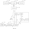
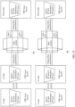
- FIG. 1 shows an architecture of a communication system to which the communication method is applicable according to an embodiment of this application.
- the communication system may include a first node 110, a second node 120, and a third node 130.
- the second node 120 may be a terminal node.
- the first node 110 may be an authorized node of the second node 120. Both the second node 120 and the first node 110 may support a first communication technology.
- the second node 120 and the first node 110 may form a first communication system.
- the two parties may communicate with each other by using the first communication technology.
- Both the first node 110 and the third node 130 may support a second communication technology.
- the first node 110 and the third node 130 may form a second communication system.
- the two parties may communicate with each other by using the second communication technology.
- the first communication technology is different from the second communication technology.
- a communication connection may be established between the first communication system and the second communication system, to form a heterogeneous communication system.
- the first node 110, the second node 120, and the third node 130 may execute a corresponding communication service and/or transmit communication service data in the heterogeneous communication system.
- the communication system may further include a fourth node 140.
- the fourth node 140 may directly communicate with the second node 120, or may indirectly communicate with the second node 120 via the first node 110, so as to provide a service for the second node 120.
- the first communication technology and the second communication technology may be different technologies. Accordingly, the communication system in this application may be a communication system obtained after different communication systems are converged.
- a wireless short-range communication technology is used as an example of the first communication technology
- a 5G cellular network communication technology is used as an example of the second communication technology.
- a communication system applicable to embodiments of this application may be obtained.
- the wireless short-range communication system described in this application may be any possible short-range communication system, such as Bluetooth, wireless fidelity (wireless fidelity, Wi-Fi), an in-vehicle general-purpose short-range communication system, or a short-range communication system that is present or may appear in the future.
- the short-range communication system has a relatively small coverage range and a relatively short communication distance.
- This application does not specifically limit a communication distance or a coverage range of the short-range communication system, and is subject to a shorter communication distance than that of the 5G communication system.
- the first communication technology is the short-range communication technology and the second communication technology is the 5G cellular network communication technology.
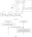
- the third node 130 may include at least one of function entities, such as a core network device including an AMF, an SMF, and a UPF, and a data network (data network, DN).
- Each node or functional entity in FIG. 2A may be connected to each other through interfaces.
- a sequence number or a name of an interface is not limited in this embodiment of this application.
- An interface defined in a 3GPP-related standard protocol of a 5G system may be used, or an interface in a future communication system may be used.
- the second node 120 may communicate with the first node 110 through a Yt interface, the first node 110 may communicate with a next generation radio access network (next generation radio access network, NG-RAN) through a Ta interface, and the second node 120 may communicate with the NG-RAN through an NWt interface.
- NG-RAN next generation radio access network
- the second node 120 and the first node 110 may communicate with the AMF through a next generation (next generation, N) 1 interface (N1 for short), the NG-RAN communicates with the AMF through an N2 interface (N2 for short), the NG-RAN communicates with the local UPF through an N3 interface (N3 for short), and the UPF communicates with the DN through an N6 interface (N6 for short).
- the AMF communicates with the SMF through an N11 interface (N11 for short), and the SMF communicates with the UPF through an N4 interface (N4 for short).
- the 5G network can perceive key information of the second node 120 such as a device status, a network status, and a service status via the first node 110, so as to remotely achieve reachability, perception, and manageability of an onsite network and a service of an industry.
- the communication system in FIG. 2B may further include a fourth node 140, and the fourth node 140 may be, for example, a TNGF node.
- the second node 120 may communicate with the first node 110 through the Yt interface, the first node 110 may communicate with the fourth node 140 through the Ta interface, and the second node 120 may communicate with the fourth node 140 through the NWt interface.
- the fourth node 140 can perceive key information of the second node 120 such as a device status, a network status, and a service status via the first node 110, so as to remotely achieve reachability, perception, and manageability of an onsite network and a service of an industry.
- the heterogeneous communication system may include the first node 110, the second node 120, the third node 130, and the fourth node 140, and to indicate a communication manner between each node and functional modules of each node, and does not limit a quantity of nodes and a sequence number or a name of an interface.
- quantities of the first node 110, the second node 120, the third node 130, and the fourth node 140 each may not be limited to 1.
- a terminal device in embodiments of this application may be a device configured to implement a wireless communication function, for example, a terminal or a chip that may be used in the terminal.
- the terminal device may include a handheld device having a wireless connection function, or a processing device connected to a wireless modem.
- the terminal device may communicate with a core network through a radio access network (radio access network, RAN), and exchange a voice and/or data with the RAN.
- radio access network radio access network
- the terminal device may include user equipment (user equipment, UE), a wireless terminal device, a mobile terminal device, a subscriber unit (subscriber unit), a subscriber station (subscriber station), a mobile station (mobile station), a mobile (mobile) console, a remote station (remote station), an access point (access point, AP), a remote terminal device (remote terminal), an access terminal device (access terminal), a user terminal device (user terminal), a user agent (user agent), a user device (user device), or the like.
- user equipment user equipment
- UE wireless terminal device
- mobile terminal device a subscriber unit (subscriber unit), a subscriber station (subscriber station), a mobile station (mobile station), a mobile (mobile) console, a remote station (remote station), an access point (access point, AP), a remote terminal device (remote terminal), an access terminal device (access terminal), a user terminal device (user terminal), a user agent (user agent), a user device (user device), or the
- the terminal device may include a mobile phone (or referred to as a "cellular" phone), a computer with a mobile terminal device, a portable, pocket-sized, handheld, computer built-in, or vehicle-mounted mobile apparatus, or a smart wearable device.
- the terminal device may be a device such as a personal communication service (personal communication service, PCS) phone, a cordless phone, a session initiation protocol (session initiation protocol, SIP) phone, a wireless local loop (wireless local loop, WLL) station, or a personal digital assistant (personal digital assistant, PDA).
- the terminal device further includes a limited device, for example, a device with low power consumption, a device with a limited storage capacity, or a device with a limited computing capability.
- the terminal device includes an information sensing device such as a barcode, radio frequency identification (radio frequency identification, RFID), a sensor, a global positioning system (global positioning system, GPS), or a laser scanner.
- the terminal device in embodiments of this application may alternatively be a wearable device.
- the wearable device may also be referred to as a wearable smart device, which is a generic term for wearable devices that are developed through intelligent design on daily wearables by using wearable technologies, such as glasses, gloves, watches, clothing, and shoes.
- the wearable device is a portable device that is worn directly on a body or integrated into a user's clothing or accessories.
- the wearable device is not only a hardware device, but also implements a powerful function through software support, data exchange, and cloud interaction.
- the wearable smart device includes a full-featured and large-sized device that can implement all or some of functions without relying on a smartphone, for example, a smart watch or smart glasses, and includes a device that focuses only on a specific type of application function and needs to be used together with another device such as a smartphone, for example, various types of smart bands, smart helmets, and smart jewelry for monitoring physical signs.
- a network device in embodiments of this application may include an access network (access network, AN) device and a radio access network (radio access network, RAN) device.
- the access network device such as a base station (for example, an access point) may be a device that communicates with a wireless terminal device through an air interface on an access network by using one or more cells.
- the base station may be configured to perform mutual conversion between a received over-the-air frame and an internet protocol (IP) packet, and is used as a router between the terminal device and a remaining part of the access network.
- IP internet protocol
- the remaining part of the access network may include an IP network.
- a network side device may further coordinate attribute management of the air interface.
- the network device may include an evolved NodeB (NodeB, eNB, or e-NodeB, evolved NodeB) in a long term evolution (long term evolution, LTE) system or a long term evolution-advanced (long term evolution-advanced, LTE-A) system; may include a next generation NodeB (next generation NodeB, gNB), a next generation evolved NodeB (next generation evolved NodeB, ng-eNB), or an en-gNB (enhanced next generation NodeB, gNB): enhanced next generation NodeB in a 5th generation (5th generation, 5G) mobile communication technology new radio (new radio, NR) system; may include a central unit (central unit, CU) and a distributed unit (distributed unit, DU) on a cloud radio access network (cloud radio access network, Cloud RAN) system; or may further include a relay device.
- NodeB evolved NodeB
- LTE long term evolution
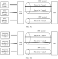
- FIG. 3 shows a first communication method according to an embodiment of this application. The method includes the following steps.
- S301 A first node obtains first information.
- the first information indicates a mapping relationship between a second node and the first node.
- the mapping relationship between the second node and the first node is a mapping relationship between an identifier of the second node and specific information of the first node.
- the identifier of the second node may be a subscription permanent identifier (subscription permanent identifier, SUPI) or a subscription concealed identifier (subscription concealed identifier, SUCI).
- the SUPI may be an international mobile subscriber identity (international mobile subscriber identity, IMSI) or a network access identifier (network access identifier, NAI) uniformly allocated by a unified data storage (unified data repository, UDR) device or a unified data management (unified data management, UDM) device in a 5G communication system.
- the SUCI may be obtained by encrypting the SUPI.
- the SUCI may be understood as an encryption form of the SUPI, and can effectively improve communication security of the second node.
- the identifier of the second node may be temporarily allocated by the first node to the second node.
- the identifier of the second node may be uniquely identified in a management domain of the first node.
- a specific form of the unique identifier allocated by the first node to the second node is not specifically limited in this embodiment of this application.
- second nodes managed by the first node are a T node 1 and a T node 2, an identifier allocated by the first node to the T node 1 may be 001, and an identifier allocated by the first node to the T node 1 may be 002.
- second nodes managed by the first node are a T node 1 and a T node 2
- an identifier allocated by the first node to the T node 1 may be A
- an identifier allocated by the first node to the T node 1 may be B.
- the specific information of the first node may be, for example, any one of a first IP address, a first port number, a first MAC address, or an identifier of the first node.
- the mapping relationship may be, for example, a first mapping relationship between the identifier of the second node and the first IP address of the first node, or a second mapping relationship between the identifier of the second node and the first port number of the first node, or a third mapping relationship between the identifier of the second node and the first MAC address of the first node, or a mapping relationship between the identifier of the second node and a first identifier of the first node.
- the first IP address is one of a plurality of public IP addresses allocated by the third node to the first node in a PDU session.
- the first port number is one of a plurality of port numbers allocated by the third node to the first node in the PDU session.
- the first MAC address is one of a plurality of MAC addresses derived by the first node based on a unique MAC address of the first node.
- the first identifier may be one of a plurality of identifiers temporarily allocated by the first node.
- the first information indicates a mapping relationship between a second node and the first node includes the following cases.
- the first information indicates the first mapping relationship between the identifier of the second node and the first IP address of the first node.
- the first information indicates the second mapping relationship between the identifier of the second node and the first port number of the first node.
- the first information indicates the third mapping relationship between the identifier of the second node and the first media access control MAC address of the first node.
- the first information indicates the mapping relationship between the identifier of the second node and the first identifier of the first node.
- the first node determines, by interacting with the second node, a PDU session associated with the second node, and obtains the first information based on the PDU session and the identifier of the second node.
- the first node obtains the first information based on the PDU session and the identifier of the second node. That is, the first node determines the mapping relationship between the first node and the second node based on the PDU session and the identifier of the second node.
- the first node may receive access-side session request information or access-side session modification request information from the second node, to determine the PDU session associated with the second node. It may be understood that the access-side session request information indicates that the second node requests the first node to allocate a PDU session, and the access-side session modification request information indicates that the second node requests the first node to modify a PDU session. Accordingly, for example, the first node determines, based on the access-side session request information or the access-side session modification request information, whether there is a PDU session that meets a current service requirement of the second node.
- the first node may determine not to establish a new PDU session for the second node, and directly allocate the PDU session to the second node. If there is no PDU session that meets the current service requirement of the second node, the first node may determine to establish a new PDU session for the first node. Optionally, after determining the PDU session for the second node, the first node may further send related information (for example, an identifier and a type of the PDU session) of the PDU session to the second node.
- related information for example, an identifier and a type of the PDU session
- a design of the provided mapping relationship between the first node and the second node in this embodiment of this application includes but is not limited to the following manners.
- Design 1 The first node establishes the first mapping relationship between the identifier of the second node and the first IP address of the first node based on the identifier of the second node and the first IP address associated with the PDU session.
- the PDU session associated with the second node includes the plurality of public IP addresses of the first node. That is, the third node allocates the plurality of public IP addresses to the first node in the PDU session, so that the first node may allocate a corresponding public IP address (that is, the first IP address) to the second node managed by the first node, and the first node establishes the first mapping relationship between the identifier of the second node and the first IP address of the first node based on the identifier of the second node and the first IP address associated with the PDU session.
- the third node allocates the plurality of public IP addresses to the first node in the PDU session, so that the first node may allocate a corresponding public IP address (that is, the first IP address) to the second node managed by the first node, and the first node establishes the first mapping relationship between the identifier of the second node and the first IP address of the first node based on the identifier of the second node and the first IP address
- Table 1 shows an example of the first mapping relationship.
- second nodes are a T node 1, a T node 2, and a T node 3.
- the third node allocates three public IP addresses to the first node in one PDU session: an IP1, an IP2, and an IP3.
- the first node may allocate a corresponding public IP address to a second node managed by the first node. For example, the first node allocates the IP1 to the T node 1, the first node allocates the IP2 to the T node 2, and the first node allocates the IP3 to the T node 3. Therefore, the first node may establish the first mapping relationship shown in Table 1.
- Table 1 Identifier of the second node First IP address of the first node Identifier of the T node 1 IP1 Identifier of the T node 2 IP2 Identifier of the T node 3 IP3
- Design 2 The first node establishes the second mapping relationship between the identifier of the second node and the first port number of the first node based on the identifier of the second node and the first port number associated with the PDU session.
- the PDU session associated with the second node includes not only one public IP address of the first node, but also includes the plurality of port numbers of the first node. That is, the third node allocates the plurality of port numbers to the first node in the PDU session, and the first node may allocate a port number to the second node managed by the first node, so that the first node may establish the second mapping relationship between the identifier of the second node and the first port number of the first node.
- Table 2 shows an example of the second mapping relationship.
- second nodes are a T node 1, a T node 2, and a T node 3.
- the third node allocates three port numbers: a P1, a P2, and a P3 to the first node in one PDU session.
- the first node may allocate a corresponding port number to a second node managed by the first node. For example, the first node allocates the P1 to the T node 1, the first node allocates the P2 to the T node 2, and the first node allocates the P3 to the T node 3. Therefore, the first node may establish the second mapping relationship shown in Table 2.
- Table 2 Identifier of the second node Port number of the first node Identifier of the T node 1 P1 Identifier of the T node 2 P2 Identifier of the T node 3 P3
- Design 3 The first node establishes the third mapping relationship between the identifier of the second node and the first MAC address of the first node based on the identifier of the second node and the first MAC address.
- the first MAC address is one of the plurality of MAC addresses derived by the first node based on the unique MAC address of the first node, and the first node may allocate a MAC address to the second node managed by the first node, so that the first node may establish the third mapping relationship between the identifier of the second node and the first MAC address of the first node.
- Table 3 shows an example of the third mapping relationship.
- second nodes are a T node 1, a T node 2, and a T node 3.
- the first node derives three MAC addresses based on the unique MAC address of the first node: a MAC address A, a MAC address B, and a MAC address C.
- the first node may allocate a corresponding MAC address to a second node managed by the first node. For example, the first node allocates the MAC address A to the T node 1, the first node allocates the MAC address B to the T node 2, and the first node allocates the MAC address C to the T node 3. Therefore, the first node may establish the third mapping relationship shown in Table 3. Table 3 Identifier of the second node MAC address of the first node Identifier of the T node 1 MAC address A Identifier of the T node 2 MAC address B Identifier of the T node 3 MAC address C
- Design 4 The first node establishes the third mapping relationship between the identifier of the second node and the first identifier of the first node based on the identifier of the second node and the first identifier.
- the first identifier is one of the plurality of identifiers that are temporarily allocated, and the first node may allocate a temporary identifier to the second node managed by the first node, so that the first node may establish the mapping relationship between the identifier of the second node and the first identifier of the first node.
- Table 4 shows an example of the mapping relationship.
- second nodes are a T node 1, a T node 2, and a T node 3.
- the first node temporarily allocates three identifiers: 01, 02, and 03.
- the first node may allocate a corresponding temporary identifier to a second node managed by the first node.
- the first node allocates the identifier 01 to the T node 1, the first node allocates the identifier 02 to the T node 2, and the first node allocates the identifier 03 to the T node 3. Therefore, the first node may establish the mapping relationship shown in Table 4.
- Table 4 Identifier of the second node Temporary identifier of the first node Identifier of the T node 1 01 Identifier of the T node 2 02 Identifier of the T node 3 03
- the first node exchanges information with the second node to obtain the first information, so that the first information may be updated in a timely manner, thereby better adapting to a requirement of the second node.
- Implementation 2 The first node has in advance managed or maintained a PDU session associated with the second node, and the first node may directly obtain the first information based on the PDU session and the identifier of the second node.
- a corresponding example of "the first node may directly obtain the first information based on the PDU session and the identifier of the second node" is similar to that in Implementation 1. For details, refer to the foregoing related descriptions. Details are not described herein again.
- S302 The first node sends the first information to the third node. Accordingly, the third node receives the first information.
- the first information when the first information indicates the first mapping relationship between the identifier of the second node and the first IP address of the first node, or the second mapping relationship between the identifier of the second node and the first port number of the first node, the first information may be carried in the PDU session update information.
- the first information when the first information indicates the third mapping relationship between the identifier of the second node and the first MAC address of the first node, or the mapping relationship between the identifier of the second node and the first identifier of the first node, the first information may be carried in any NAS information obtained after the first node is successfully registered.
- the third node identifies, based on the first information, the second node associated with the PDU session.
- the third node identifies the second node associated with the PDU session. That is, the third node identifies the second node associated with user-plane data.
- the third node may directly identify, based on the mapping relationship indicated by the first information, the second node associated with the PDU session. For example, the third node may identify, based on the first mapping relationship, the second node associated with the PDU session. For another example, the third node may identify, based on the second mapping relationship, the second node associated with the PDU session. For another example, the third node may identify, based on the third mapping relationship, the second node associated with the PDU session.
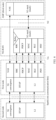
- FIG. 4 shows a user-plane protocol architecture to which the first communication method is applicable according to an embodiment of this application.
- the third node is a UPF.
- the user-plane protocol architecture includes, from top to bottom, a service data adaptation protocol (service data adaptation protocol, SDAP) layer, a packet data convergence protocol (packet data convergence protocol, PDCP) layer, a radio link control (Radio link control, RLC) layer, a media access control (medium access control, MAC) layer, a physical layer (physical layer, PHY), and the like.
- SDAP service data adaptation protocol
- PDCP packet data convergence protocol
- RLC Radio link control
- media access control medium access control
- MAC media access control
- PHY physical layer
- An N9 stack is an N9 protocol stack, and an N9 interface is an interface between 5G core network elements.
- a user datagram protocol (user datagram protocol, UDP)/internet protocol (internet protocol, IP) is a data transmission protocol.
- the UDP indicates unreliable data transmission (different from a TCP, the TCP is reliable transmission).
- the IP provides an addressing manner for data transmission, and data routing and addressing are performed based on the IP.
- a GPRS tunnelling protocol on a user plane (GPRS tunnelling protocol-user, GTP-U) provides a data encapsulation manner.
- a GTP-U frame structure may include tunnelling information, a message type, a sequence number, and the like.
- An L1 layer refers to a physical layer, is a lowest layer in a computer network model, and provides mechanical, electronic, functional, and standard features for creating, maintaining, and removing physical links required for data transmission. In brief, the physical layer ensures that original data may be transmitted over a variety of physical media.
- An L2 layer refers to a data link layer, is a second layer in a computer network reference model, and is between a physical layer and a network layer.
- the data link layer provides a service for the network layer based on a service provided by the physical layer.
- a basic service of the data link layer is to reliably transmit data from the network layer to a network layer of a target machine of an adjacent node.
- the L1 and the L2 may be configured to receive and send data at a link layer.
- the relay may relay received information.
- the first node may encapsulate the public IP address of the first node in a data packet of the PDU layer.
- the UPF may identify, based on the public IP address of the first node in the IP data packet and the first mapping relationship between the identifier of the second node and the first IP address of the first node, the second node associated with the PDU session.
- second nodes are a T node 1, a T node 2, and a T node 3.
- a plurality of PDU sessions may be established between the UPF and the first node.
- a PDU session 1 and a PDU session 2 may exist.
- the PDU session 1 is used to transmit data of the T node 1 and the T node 2
- the PDU session 2 is used to transmit data of the T node 3. That is, the PDU session 1 is associated with the T node 1 and the T node 2, and the PDU session 2 is associated with the T node 3.
- the PDU session 1 includes IP addresses of the first node: an IP1 and an IP2, and the PDU session 2 includes an IP address of the first node: an IP3.
- the first node allocates the IP1 to the T node 1, the first node allocates the IP2 to the T node 2, and the first node allocates the IP3 to the T node 3.
- the UPF may determine, based on the first mapping relationship between the identifier of the second node and the first IP address of the first node, that the second node associated with the PDU session 1 is the T node 1. For another example, if the public IP address of the first node in the IP data packet that is of the PDU session 1 and that is received by the UPF is the IP2, the UPF may determine, based on the first mapping relationship between the identifier of the second node and the first IP address of the first node, that the second node associated with the PDU session 1 is the T node 2.
- the UPF may determine, based on the first mapping relationship between the identifier of the second node and the first IP address of the first node, that the second node associated with the PDU session 2 is the T node 3.
- the first node may encapsulate the port number of the first node in a data packet of the PDU layer.
- the UPF may identify, based on the port number of the first node in the IP data packet and the second mapping relationship between the identifier of the second node and the first port number of the first node, the second node associated with the PDU session.
- the PDU session 1 includes port numbers of the first node: a P1 and a P2.
- the PDU session 2 includes a port number of the first node: a P3.
- the first node allocates the P1 to the T node 1, the first node allocates the P2 to the T node 2, and the first node allocates the P3 to the T node 3.
- the UPF may determine, based on the second mapping relationship between the identifier of the second node and the first port number of the first node, that the second node associated with the PDU session 1 is the T node 1. For another example, if the port number of the first node in the IP data packet that is of the PDU session 1 and that is received by the UPF is the P2, the UPF may determine, based on the second mapping relationship between the identifier of the second node and the first port number of the first node, that the second node associated with the PDU session 1 is the T node 2.
- the UPF may determine, based on the second mapping relationship between the identifier of the second node and the first port number of the first node, that the second node associated with the PDU session 2 is the T node 3.
- the first node may encapsulate the MAC address of the first node in a data packet of the PDU layer.
- the UPF may identify, based on the MAC address of the first node in the IP data packet and the third mapping relationship between the identifier of the second node and the first MAC address of the first node, the second node associated with the PDU session.
- second nodes are a T node 1, a T node 2, and a T node 3.
- a plurality of sessions may be established between the UPF and the first node.
- a PDU session 1 and a PDU session 2 may exist.
- the PDU session 1 is used to transmit data of the T node 1 and the T node 2
- the PDU session 2 is used to transmit data of the T node 3. That is, the PDU session 1 is associated with the T node 1 and the T node 2, and the PDU session 2 is associated with the T node 3.
- the PDU session 1 and the PDU session 2 include a same IP address of the first node: an IP1.
- Temporary MAC addresses derived by the first node based on the unique MAC address of the first node include a MAC address A, a MAC address B, and a MAC address C.
- the first node allocates the MAC address A to the T node 1, the first node allocates the MAC address B to the T node 2, and the first node allocates the MAC address C to the T node 3.
- the PDU session 1 is used to transmit data of the T node 1 and the T node 2
- the PDU session 2 is used to transmit data of the T node 3. That is, the PDU session 1 is associated with the T node 1 and the T node 2, and the PDU session 2 is associated with the T node 3.
- the UPF may determine, based on the third mapping relationship between the identifier of the second node and the first MAC address of the first node, that the second node associated with the PDU session 1 is the T node 1. For another example, if the MAC address of the first node in the IP data packet that is of the PDU session 1 and that is received by the UPF is B, the UPF may determine, based on the third mapping relationship between the identifier of the second node and the first MAC address of the first node, that the second node associated with the PDU session 1 is the T node 2.
- the UPF may determine, based on the third mapping relationship between the identifier of the second node and the first MAC address of the first node, that the second node associated with the PDU session 2 is the T node 3.
- the first node may encapsulate the identifier of the first node in a data packet of the PDU layer.
- the UPF may identify, based on the identifier of the first node in the IP data packet and the mapping relationship between the identifier of the second node and the first identifier of the first node, the second node associated with the PDU session.
- second nodes are a T node 1, a T node 2, and a T node 3.
- a plurality of sessions may be established between the UPF and the first node.
- a PDU session 1 and a PDU session 2 may exist.
- the PDU session 1 is used to transmit data of the T node 1 and the T node 2
- the PDU session 2 is used to transmit data of the T node 3. That is, the PDU session 1 is associated with the T node 1 and the T node 2, and the PDU session 2 is associated with the T node 3.
- the PDU session 1 and the PDU session 2 include a same IP address of the first node: an IP1.
- the first node has temporary identifiers: 01, 02, and 03.
- the first node allocates the temporary identifier 01 to the T node 1, the first node allocates the temporary identifier 02 to the T node 2, and the first node allocates the temporary identifier 03 to the T node 3.
- the UPF may determine, based on the mapping relationship between the identifier of the second node and the first identifier of the first node, that the second node associated with the PDU session 1 is the T node 1. For another example, if the temporary identifier of the first node in the IP data packet that is of the PDU session 1 and that is received by the UPF is 02, the UPF may determine, based on the mapping relationship between the identifier of the second node and the first identifier of the first node, that the second node associated with the PDU session 1 is the T node 2.
- the UPF may determine, based on the mapping relationship between the identifier of the second node and the first identifier of the first node, that the second node associated with the PDU session 2 is the T node 3.
- the first node When allocating the PDU session to the second node (for example, in the PDU session establishment or PDU session modification procedure), the first node further configures a packet filter packetfilter(s) (which may also be referred to as a filtering policy) for the second node, so that the second node in the PDU session is associated with the packet filter.
- the packet filter may be used to screen or determine a QoS flow corresponding to the second node in the PDU session, and the QoS flow is used to transmit data associated with the second node.
- the third node may identify, based on the packet filter and the mapping relationship between the first node and the second node, the second node associated with the PDU session.
- QoS flows corresponding to the second node in the PDU session are a QoS flow 1 and a QoS flow 2.
- the first node sends, to the third node, a packet filter configured by the first node for the second node.
- the third node may screen the QoS flow 1 and the QoS flow 2 based on the packet filter, so that the third node determines that a service flow corresponding to the second node is placed in the QoS flow 1 and the QoS flow 2 for transmission.
- the third node may identify, based on the public IP address of the first node in the packet filter and the first mapping relationship between the identifier of the second node and the first IP address of the first node, the second node associated with the PDU session; or if the packet filter includes the port number (port) of the first node, the third node may identify, based on the port number (port) of the first node in the packet filter and the second mapping relationship between the identifier of the second node and the first port number of the first node, the second node associated with the PDU session; or if the packet filter includes the MAC address of the first node, the third node may identify, based on the MAC address of the first node in the packet filter and the third mapping relationship between the identifier of the second node and the first MAC address of the first node, the second node associated with the PDU session; or if the packet filter includes the temporary identifier of the first node
- the third node may identify, based on the packet filter and the mapping relationship between the first node and the second node, the second node associated with the PDU session, thereby effectively improving accuracy of identifying the second node by the third node.
- the first node may send the mapping relationship between the second node and the first node to a core network, so that the third node may identify (that is, perceive or manage) the second node, thereby managing a service provided by the second node, to better meet a requirement of the second node.
- the second node needs to include the identifier of the second node in control information to be reported to the third node.
- the third node may also identify, based on the mapping relationship and the identifier of the second node, data associated with the second node, so that the third node may accordingly adjust configuration information (for example, a QoS flow related parameter) of the second node.
- FIG. 6 shows a control-plane protocol architecture to which the first communication method is applicable according to an embodiment of this application.
- the third node is an AMF.
- the control-plane protocol architecture includes, from top to bottom, a radio resource control (radio resource control, RRC) layer, a PDCP layer, an RLC layer, a MAC layer, a PHY layer, and the like.
- RRC radio resource control
- An N2stack is an N2 protocol stack
- an N2 interface is an interface between a 5G core network element and an NG-RAN
- the first node and the second node may communicate with each other by using any one of a communication link (sparkLinkL2) protocol, a direct transfer application part (direct transfer application part, DTAP) protocol, and 5G convergence.
- sparkLinkL2 a communication link
- DTAP direct transfer application part
- the first node may communicate with the NG-RAN at the RRC layer, the PDCP layer, the RLC layer, the MAC layer, and the physical layer.
- the NG-RAN communicates with the AMF (the third node) through the N2stack interface. Therefore, the second node may indirectly obtain, via the first node, a service provided by the third node.
- the second node does not support NAS signaling, and the first node and the AMF support NAS signaling. Therefore, the second node may send to-be-reported control information of the AMF to the first node, and the first node sends both the control information and the identifier of the second node to the AMF based on NAS information. In this way, the AMF may identify, based on the identifier of the second node and the mapping relationship between the second node and the first node, data (for example, a QoS flow) associated with the second node.
- data for example, a QoS flow
- FIG. 7A further provides a corresponding schematic diagram of a scenario.
- second nodes are a T node 1 to a T node N.
- the first node may send an identifier of a T node and control information corresponding to the T node to the AMF at the same time, so that the AMF may identify, based on the identifier of the second node and the mapping relationship between the first node and the identifier of the second node, data associated with the second node.
- FIG. 7B shows a communication procedure between the second node and the third node when there is no PDU session.
- S701 The second node sends second information to the first node. Accordingly, the first node receives the second information.
- the second information includes link status information and/or node status information.
- the link status information includes at least one of a short-range measurement amount (short-range air interface status information) and a link status measurement amount between a short-range node and a 5G core network.
- the short-range measurement amount includes at least one of a reference signal received power (reference signal received power, RSRP), a reference signal received quality (reference signal received quality, RSRQ), a signal to interference plus noise ratio (signal to interference plus noise ratio, SINR), a channel quality indicator (channel quality indicator, CQI), a precoding matrix indicator (precoding matrix indicator, PMI), a rank indication (rank indication, RI), and a timestamp.
- the link status measurement amount between the short-range node and the 5G core network includes at least one of a round-trip delay (round-trip time, RTT), a packet loss rate, a jitter, and a timestamp.
- the second node may send the second information to the first node by using a Bluetooth technology or a Wi-Fi technology.
- S702 The first node adds the identifier of the second node to the second information, to obtain third information.
- the first node may add the identifier of the second node to a header or a tail of a data packet corresponding to the second information, to obtain the third information.
- S703 The first node sends the third information to the third node. Accordingly, the third node receives the third information.
- the third information may be carried in a NAS message.
- the first node may send the third information to the third node through the NAS message.
- the third node identifies, based on the mapping relationship between the first node and the second node, the second node associated with the third information.
- mapping relationship between the first node and the second node is determined by the third node based on the pre-received first information.
- the first information indicates a mapping relationship between a second node and a first node includes: The first information indicates a first mapping relationship between an identifier of the second node and a first IP address of the first node; or the first information indicates a second mapping relationship between an identifier of the second node and a first port number of the first node; or the first information indicates a third mapping relationship between an identifier of the second node and a first media access control MAC address of the first node; or the first information indicates a mapping relationship between an identifier of the second node and a first identifier of the first node.
- the third node may identify, based on the identifier of the second node and the first mapping relationship, the second node associated with the third information; or identify, based on the identifier of the second node and the second mapping relationship, the second node associated with the third information; or identify, based on the identifier of the second node and the third mapping relationship, the second node associated with the third information; or identify, based on the identifier of the second node and the mapping relationship between the identifier of the second node and the first identifier of the first node, the second node associated with the third information.
- the first node may add the identifier of the second node to the control information of the second node, and send the identifier and control information to the third node.
- the third node may identify, based on the first information, data associated with the second node, so that the third node accordingly adjusts the configuration information of the second node.
- the first communication method provided in this embodiment of this application may further include the following steps.
- S304 The third node determines configuration information based on the first information.
- the configuration information includes at least one of running status management information, node parameter update information, a link status detection policy, a node status reporting policy, and a QoS configuration policy of the second node.
- running status management information node parameter update information
- link status detection policy node parameter update information
- node status reporting policy a QoS configuration policy of the second node.
- the running status management information includes any one of a power-on state, a power-off state, and a sleep state of the second node.
- the node status update information includes update information corresponding to any one of version information, power information, hardware information, and software information of the second node.
- the link status detection policy includes at least one of a measurement object, a reporting object, a reporting threshold, a reporting period, and an event parameter.
- the node status reporting policy includes at least one of a reporting object, a reporting period, and a reporting event.
- the QoS configuration policy includes a correspondence between the second node and the QoS flow in the PDU session.
- S305 The third node sends the configuration information to the first node. Accordingly, the first node receives the configuration information.
- S306 The first node sends the configuration information to the second node. Accordingly, the second node receives the configuration information.
- the first node may send the configuration information to the second node in a Bluetooth manner.
- the second node configures the second node based on the configuration information.
- Example 1 When the configuration information includes the running status management information of the second node, the second node may configure a running status of the second node based on the running status management information.
- Example 2 When the configuration information includes the node parameter update information of the second node, the second node may configure a node parameter (for example, version information, power information, hardware information, and software information) of the second node based on the running status management information.
- a node parameter for example, version information, power information, hardware information, and software information
- Example 3 When the configuration information includes the link status detection policy of the second node, the second node may configure a link status monitoring mechanism of the second node based on the link status detection policy, for example, configure at least one of the measurement object, the reporting object, the reporting threshold, the reporting period, and the event parameter.
- the second node may configure a node status reporting mechanism of the second node based on the node status reporting policy, for example, configure at least one of the reporting object, the reporting period, and the reporting event.
- Example 5 When the configuration information includes the QoS configuration policy of the second node, the second node may configure, based on the QoS configuration policy, a transmission channel used for data associated with the second node, or adjust the transmission channel used for data associated with the second node.
- Example 6 When the configuration information includes the running status management information and the node parameter update information of the second node, the second node may configure a running status of the second node based on the running status management information, and the second node may configure a node parameter (for example, version information, power information, hardware information, and software information) of the second node based on the running status management information.
- a node parameter for example, version information, power information, hardware information, and software information
- Example 7 When the configuration information includes the link status detection policy and the node status reporting policy of the second node, the second node may configure a link status monitoring mechanism of the second node based on the link status detection policy, for example, configure at least one of the measurement object, the reporting object, the reporting threshold, the reporting period, and the event parameter. In addition, the second node may configure a node status reporting mechanism of the second node based on the node status reporting policy, for example, configure at least one of the reporting object, the reporting period, and the reporting event.
- Example 8 When the configuration information includes the link status detection policy, the node status reporting policy, and the QoS configuration policy of the second node, the second node may configure a link status monitoring mechanism of the second node based on the link status detection policy, for example, configure at least one of the measurement object, the reporting object, the reporting threshold, the reporting period, and the event parameter. In addition, the second node may configure a node status reporting mechanism of the second node based on the node status reporting policy, for example, configure at least one of the reporting object, the reporting period, and the reporting event. In addition, the second node may configure, based on the QoS configuration policy, a transmission channel used for data associated with the second node, or adjust the transmission channel used for data associated with the second node.
- Example 9 When the configuration information includes the running status management information, the node parameter update information, the link status detection policy, the node status reporting policy, and the QoS configuration policy of the second node, the second node may configure a running status of the second node based on the running status management information. In addition, the second node may configure a node parameter of the second node based on the running status management information. In addition, the second node may configure a link status monitoring mechanism of the second node based on the link status detection policy. In addition, the second node may configure a node status reporting mechanism of the second node based on the node status reporting policy. In addition, the second node may configure, based on the QoS configuration policy, a transmission channel of data associated with the second node.
- the configuration information may further include another parameter. This is not specifically limited in this embodiment of this application.
- the third node may manage and control at least one of the running status management information, the node parameter update information, the link status detection policy, the node status reporting policy, and the QoS configuration policy of the second node, so that the third node may provide the second node with a service that is more adaptive to the second node.
- FIG. 9 shows a second communication method according to an embodiment of this application.
- the method is performed by a first node and a fourth node.
- the method includes the following steps.
- the first node may obtain a fourth mapping relationship between an identifier of a second node and an IP address of the second node.
- Table 5 shows an example of the fourth mapping relationship.
- second nodes are a T node 1, a T node 2, and a T node 3.
- a private IP address corresponding to the T node 1 is an IP4
- a private IP address corresponding to the T node 2 is an IP5
- a private IP address corresponding to the T node 3 is an IP6.
- the first node may establish the mapping relationship shown in Table 1.
- Table 5 Identifier of the second node Private IP address of the second node Identifier of the T node 1 IP4 Identifier of the T node 2 IP5 Identifier of the T node 3 IP6
- S902 The first node sends the fourth mapping relationship to the fourth node. Accordingly, the fourth node receives the fourth mapping relationship.
- the fourth node determines the second node based on the fourth mapping relationship.
- the fourth node may identify the second node based on the private IP address included in the data packet of the second node and the fourth mapping relationship.
- the fourth node may determine the second node based on the IP address of the second node and the fourth mapping relationship between the identifier of the second node and the IP address of the second node, so that the fourth node may identify (that is, perceive or manage) the second node, thereby better providing a service for the second node.
- a third node allocates only one public IP address to the first node in a PDU session, and the first node may allocate a private IP address to a second node managed by the first node. In this way, the first node may establish a fifth mapping relationship between the identifier of the second node and the private IP address of the second node, and send the fifth mapping relationship to the third node.
- the third node maintains or manages a first correspondence between the PDU session and the public IP address of the first node, and maintains or manages a second correspondence between the public IP address of the first node and the private IP address of the second node.
- the third node may maintain a third correspondence between a PDU session identifier and the private IP address of the second node based on the first correspondence, the first correspondence, and the fifth mapping relationship. Therefore, when receiving a packet filter associated with the PDU session, the third node may identify the second node based on the third correspondence and the private IP address that is of the second node and that is included in the packet filter.
- QoS flows corresponding to the second node (that is, a T node) in the PDU session are a QoS flow 1 and a QoS flow 2.
- the first node sends, to the third node, a packet filter configured by the first node for the T node, and the packet filter may include a private IP address IP(T) of the T node.
- the third node may screen, based on the packet filter, the QoS flow 1 and the QoS flow 2 corresponding to the T node, and the third node may place a service flow corresponding to the T node in the QoS flow 1 and the QoS flow 2 for transmission.
- second nodes are a T node 1, a T node 2, and a T node 3.
- a private IP address corresponding to the T node 1 is an IP7
- a private IP address corresponding to the T node 2 is an IP8,
- a private IP address corresponding to the T node 3 is an IP9.
- the private IP addresses are the IP7, the IP8, and the IP9. All the private IP addresses are associated with a public IP address IP1 of the first node, and the public IP address IP1 is associated with a PDU session 1.
- the private IP address of the second node that is included in a filtered data packet associated with the PDU session 1 and that is received by the third node is the IP7, and the third node may identify the second node as the T node 1.
- the private IP address of the second node that is included in a filtered data packet associated with the PDU session 1 and that is received by the third node is the IP8, and the third node may identify the second node as the T node 2.
- the private IP address of the second node that is included in a filtered data packet associated with the PDU session 1 and that is received by the third node is the IP9, and the third node may identify the second node as the T node 3.
- FIG. 11 is a schematic block diagram of an apparatus 1100 according to an embodiment of this application.
- the apparatus 1100 is configured to implement a function of the first node in the foregoing method embodiments.
- the apparatus may be a software module or a chip system.
- the chip may include a chip, or may include a chip and another discrete device.
- the apparatus 1100 includes a processing module 1101 and a transceiver module 1102.
- the processing module 1101 is configured to obtain first information.
- the first information indicates a mapping relationship between a second node and the first node.
- the transceiver module 1102 is configured to send the first information to a third node.
- the first information identifies the second node associated with a protocol data unit PDU session.
- the transceiver module 1102 may also be referred to as a communication interface, a communication unit, an input/output interface, or the like.
- the first information indicates the mapping relationship between the second node and the first node includes: The first information indicates a first mapping relationship between an identifier of the second node and a first IP address of the first node, or a second mapping relationship between an identifier of the second node and a first port number of the first node, or a third mapping relationship between an identifier of the second node and a first media access control MAC address of the first node, or a mapping relationship between an identifier of the second node and a first identifier of the first node.
- the first IP address is one of a plurality of public IP addresses allocated to the first node in the PDU session.
- the first port number is one of a plurality of port numbers allocated to the first node in the PDU session, and the PDU session includes one public IP address of the first node.
- the first identifier may be one of a plurality of identifiers temporarily allocated by the first node.
- the first information is carried in a non-access stratum NAS message
- the NAS message is any one of NAS messages in a PDU session establishment procedure, a PDU session modification procedure, and a registration procedure.
- the NAS message may include but is not limited to any one of a registration request message, an access session request message, a PDU session establishment request message, and a PDU session modification request message.
- the first information when the first information indicates the first mapping relationship between the identifier of the second node and the first IP address of the first node, or the second mapping relationship between the identifier of the second node and the first port number of the first node, the first information may be carried in PDU session update information.
- the first information when the first information indicates the third mapping relationship between the identifier of the second node and the first MAC address of the first node, or the mapping relationship between the identifier of the second node and the first identifier of the first node, the first information may be carried in any NAS information obtained after the first node is successfully registered.
- the second node in the PDU session is associated with a packet filter, and the packet filter is used to determine a quality of service QoS flow corresponding to the second node in the PDU session.
- the transceiver module 1102 is further configured to receive access-side session request information or access-side session modification request information from the second node.
- the processing module 1101 may further: determine that the second node is associated with the PDU session; and establish the first mapping relationship based on the identifier of the second node and the first IP address associated with the PDU session; or establish the second mapping relationship based on the identifier of the second node and the first port number associated with the PDU session; or establish the third mapping relationship based on the identifier of the second node and the first MAC address; or establish the mapping relationship between the identifier of the second node and the first identifier of the first node based on the identifier of the second node and the first identifier.
- the access-side session request information indicates that the second node requests the first node to allocate a PDU session
- the access-side session modification request information indicates that the second node requests the first node to modify a PDU session.
- the transceiver module 1102 may further receive second information from the second node.
- the second information includes link status information and/or node status information.
- the processing module 1101 may further add the identifier of the second node to the second information, to obtain third information.
- the transceiver module 1102 may send the third information to the third node.
- the link status information includes at least one of a short-range measurement amount (short-range air interface status information) and a link status measurement amount between a short-range node and a 5G core network.
- the transceiver module 1102 may further: receive configuration information from the third node, where the configuration information includes at least one of running status management information, node parameter update information, a link status detection policy, and a QoS configuration policy of the second node; and send the configuration information to the second node.
- the link status detection policy includes at least one of a measurement object, a reporting object, a reporting threshold, a reporting period, and an event parameter.
- the running status management information includes any one of a power-on state, a power-off state, and a sleep state of the second node.
- the node status update information includes update information corresponding to any one of version information, power information, hardware information, and software information of the second node.
- a node status reporting policy includes at least one of a reporting object, a reporting period, and a reporting event.
- the transceiver module 1102 may further send a fourth mapping relationship between the identifier of the second node and an IP address of the second node to a fourth node.
- the transceiver module 1102 communicates with the second node based on a first communication technology, and communicates with the third node based on a second communication technology.
- FIG. 12 is a schematic block diagram of an apparatus 1200 according to an embodiment of this application.
- the apparatus 1200 is configured to implement a function of the first node in the foregoing method embodiments.
- the apparatus may be a software module or a chip system.
- the chip may include a chip, or may include a chip and another discrete device.
- the apparatus 1200 includes a processing module 1201 and a transceiver module 1202.
- the processing module 1201 is configured to receive first information.
- the first information indicates a mapping relationship between a second node and the first node.
- the transceiver module 1202 is configured to identify, based on the first information, the second node associated with a protocol data unit PDU session.
- that the first information indicates the mapping relationship between the second node and the first node includes: The first information indicates a first mapping relationship between an identifier of the second node and a first IP address of the first node, or a second mapping relationship between an identifier of the second node and a first port number of the first node, or a third mapping relationship between an identifier of the second node and a first media access control MAC address of the first node, or a mapping relationship between an identifier of the second node and a first identifier of the first node.
- the first IP address is any one of a plurality of public IP addresses allocated to the first node in the PDU session.
- the first port number is any one of a plurality of port numbers allocated to the first node in the PDU session, and the PDU session includes one public IP address of the first node.
- the first MAC address is one of a plurality of MAC addresses derived by the first node based on a unique MAC address of the first node.
- the first identifier may be one of a plurality of identifiers temporarily allocated by the first node.
- the first information is carried in a non-access stratum NAS message
- the NAS message is any one of NAS messages in a PDU session establishment procedure, a PDU session modification procedure, and a registration procedure.
- the NAS message may include but is not limited to any one of a registration request message, an access session request message, a PDU session establishment request message, and a PDU session modification request message.
- the first information when the first information indicates the first mapping relationship between the identifier of the second node and the first IP address of the first node, or the second mapping relationship between the identifier of the second node and the first port number of the first node, the first information may be carried in PDU session update information.
- the first information when the first information indicates the third mapping relationship between the identifier of the second node and the first MAC address of the first node, or the mapping relationship between the identifier of the second node and the first identifier of the first node, the first information may be carried in any NAS information obtained after the first node is successfully registered.
- the second node in the PDU session is associated with a packet filter
- the packet filter is used to determine a quality of service QoS flow corresponding to the second node in the PDU session
- the QoS flow is used to transmit data associated with the second node
- the processing module 1201 may: identify, based on the public IP address of the first node in the packet filter and the first mapping relationship, the second node associated with the PDU session; or identify, based on the port number of the first node in the packet filter and the second mapping relationship, the second node associated with the PDU session; or identify, based on the MAC address of the first node in the packet filter and the third mapping relationship, the second node associated with the PDU session; or identify, based on the identifier of the first node in the packet filter and the mapping relationship between the identifier of the second node and the first identifier of the first node, the second node associated with the PDU session.
- the transceiver module 1202 may further receive third information.
- the third information includes the identifier of the second node, link status information, and/or node status information.
- the processing module 1201 may further: identify, based on the identifier of the second node and the first mapping relationship, the second node associated with the third information; or identify, based on the identifier of the second node and the second mapping relationship, the second node associated with the third information; or identify, based on the identifier of the second node and the third mapping relationship, the second node associated with the third information; or identify, based on the identifier of the second node and the mapping relationship between the identifier of the second node and the first identifier of the first node, the second node associated with the third information.
- the processing module 1201 may further: determine configuration information based on the first information, where the configuration information includes at least one of running status management information, node parameter update information, a link status detection policy, and a QoS configuration policy of the second node; and send the configuration information to the first node.
- the link status detection policy includes at least one of a measurement object, a reporting object, a reporting threshold, a reporting period, and an event parameter.
- the running status management information includes any one of a power-on state, a power-off state, and a sleep state of the second node.
- the node status update information includes update information corresponding to any one of version information, power information, hardware information, and software information of the second node.
- Anode status reporting policy includes at least one of a reporting object, a reporting period, and a reporting event.
- the transceiver module 1202 communicates with the first node based on a second communication technology; and provides, based on the second communication technology, a service for the second node that is based on a first communication technology.
- FIG. 13 is a schematic block diagram of an apparatus 1300 according to an embodiment of this application.
- the apparatus 1300 is configured to implement a function of the first node in the foregoing method embodiments.
- the apparatus may be a software module or a chip system.
- the chip may include a chip, or may include a chip and another discrete device.
- the apparatus 1300 includes a processing module 1301 and a transceiver module 1302.
- the transceiver module 1302 is configured to receive configuration information from the first node.
- the configuration information includes at least one of running status management information, node parameter update information, a link status detection policy, and a quality of service QoS configuration policy of a second node.
- the processing module 1301 is configured to configure the second node based on the configuration information.
- the link status detection policy includes at least one of a measurement object, a reporting object, a reporting threshold, a reporting period, and an event parameter.
- the running status management information includes any one of a power-on state, a power-off state, and a sleep state of the second node.
- the node status update information includes update information corresponding to any one of version information, power information, hardware information, and software information of the second node.
- a node status reporting policy includes at least one of a reporting object, a reporting period, and a reporting event.
- the transceiver module 1302 may further send access-side session request information or access-side session modification request information to the first node. It may be understood that the access-side session request information indicates that the second node requests the first node to allocate a PDU session, and the access-side session modification request information indicates that the second node requests the first node to modify a PDU session.
- the transceiver module 1302 may further send second information to the first node.
- the second information includes link status information and/or node status information.
- the link status information includes at least one of a short-range measurement amount (short-range air interface status information) and a link status measurement amount between a short-range node and a 5G core network.
- the transceiver module 1302 communicates with the first node based on a first communication technology, and obtains a service provided based on a second communication technology from a third node.
- FIG. 14 is a schematic block diagram of an apparatus 1400 according to an embodiment of this application.
- the apparatus 1400 is configured to implement a function of the fourth node in the foregoing method embodiments.
- the apparatus may be a software module or a chip system.
- the chip may include a chip, or may include a chip and another discrete device.
- the apparatus 1400 includes a processing module 1401 and a transceiver module 1402.
- the transceiver module 1402 is configured to receive a fourth mapping relationship between an identifier of a second node and an IP address of the second node from a first node.
- the processing module 1401 is configured to determine the second node based on a third mapping relationship and the IP address of the second node.
- Module division in embodiments of this application is an example, is only logical function division, and may be other division during actual implementation.
- functional modules in embodiments of this application may be integrated into one processor, or may exist alone physically, or two or more modules may be integrated into one module.
- the integrated module may be implemented in a form of hardware, or may be implemented in a form of a software functional module.
- FIG. 15 is a schematic diagram of an apparatus 1500 according to an embodiment of this application.
- the apparatus 1500 may be a node, or a component in a node, for example, a chip or an integrated circuit.
- the apparatus 1500 may include at least one processor 1502 and a communication interface 1504. Further, optionally, the apparatus may further include at least one memory 1501. Further, optionally, a bus 1503 may be further included.
- the memory 1501, the processor 1502, and the communication interface 1504 are connected through the bus 1503.
- the memory 1501 is configured to provide storage space, and the storage space may store data such as an operating system and a computer program.
- the memory 1501 mentioned in this embodiment of this application may be a volatile memory or a non-volatile memory, or may include both a volatile memory and a non-volatile memory.
- the non-volatile memory may be a read-only memory (read-only memory, ROM), a programmable read-only memory (programmable ROM, PROM), an erasable programmable read-only memory (erasable PROM, EPROM), an electrically erasable programmable read-only memory (electrically EPROM, EEPROM), or a flash memory.
- the volatile memory may be a random-access memory (random access-memory, RAM), and is used as an external cache.
- RAM random access-memory
- many forms of RAMs may be used, for example, a static random-access memory (static RAM, SRAM), a dynamic random-access memory (dynamic RAM, DRAM), a synchronous dynamic random-access memory (synchronous DRAM, SDRAM), a double data rate synchronous dynamic random-access memory (double data rate SDRAM, DDR SDRAM), an enhanced synchronous dynamic random-access memory (enhanced SDRAM, ESDRAM), a synchlink dynamic random-access memory (synchlink DRAM, SLDRAM), and a direct rambus random-access memory (direct rambus RAM, DR RAM).
- static random-access memory static random-access memory
- DRAM dynamic random-access memory
- DRAM synchronous dynamic random-access memory
- double data rate SDRAM double data rate SDRAM
- DDR SDRAM double data rate SDRAM
- ESDRAM enhanced synchronous dynamic random-access
- the processor 1502 is a module for performing an arithmetic operation and/or a logical operation, and may be specifically one or a combination of processing modules such as a central processing unit (central processing unit, CPU), a graphics processing unit (graphics processing unit, GPU), a microprocessor unit (microprocessor unit, MPU), an application-specific integrated circuit (application-specific integrated circuit, ASIC), a field programmable logic gate array (field programmable gate array, FPGA), a complex programmable logic device (complex programmable logic device, CPLD), a coprocessor (assisting the central processing unit to complete corresponding processing and application), and a microcontroller unit (microcontroller unit, MCU).
- processing modules such as a central processing unit (central processing unit, CPU), a graphics processing unit (graphics processing unit, GPU), a microprocessor unit (microprocessor unit, MPU), an application-specific integrated circuit (application-specific integrated circuit, ASIC), a field programmable logic gate array (field programmable gate array, FPGA),
- the processor when the processor is a general-purpose processor, an ASIC, an FPGA or another programmable logic device, a discrete gate or transistor logic device, or a discrete hardware component, the memory (storage module) may be integrated into the processor.
- the communication interface 1504 may be configured to provide an information input or output for the at least one processor; and/or the communication interface may be configured to receive data sent from an external environment and/or send data to an external environment.
- the communication interface may be an interface of a wired link, including an Ethernet cable or the like; or may be an interface of a wireless link (Wi-Fi, Bluetooth, universal wireless transmission, an in-vehicle short-range communication technology, or the like).
- the communication interface 1504 may further include a transmitter (for example, a radio frequency transmitter or an antenna), a receiver, or the like that is coupled to the interface.
- the apparatus 1500 may be the first node or a component in the first node in the foregoing method embodiments, for example, a chip or an integrated circuit.
- the apparatus 1500 may be the third node or a component in the third node in the foregoing method embodiments, for example, a chip or an integrated circuit.
- the apparatus 1500 may be the second node or a component in the second node in the foregoing method embodiments, for example, a chip or an integrated circuit.
- the apparatus 1500 may be the fourth node or a component in the fourth node in the foregoing method embodiments, for example, a chip or an integrated circuit.
- the terminal may be a smart terminal such as a smartphone, a notebook computer, or a tablet computer that has a short-range communication function, a mouse, a keyboard, a headset, a sound box, an in-vehicle playback device, or the like.
- the terminal includes a first apparatus and/or a second apparatus.
- the first apparatus and the second apparatus may be respectively the first node and the second node in the embodiment shown in FIG. 3 .
- the first apparatus and the second apparatus may be of a same type or different types.
- the chip When the communication apparatus is a chip, the chip includes a transceiver unit and a processing unit.
- the transceiver unit may be an input/output circuit or a communication interface.
- the processing unit is a processor, a microprocessor, or an integrated circuit integrated on the chip.
- the method and the apparatus are conceived based on a same or similar technical concept.
- the method and the apparatus have similar principles for resolving the problems. Therefore, for implementation of the apparatus and the method, refer to each other. Details of repeated parts are not described.
- An embodiment of this application further provides a computer-readable storage medium, including instructions.
- the instructions When the instructions are run on a computer, the computer is enabled to perform the methods in the foregoing embodiments.
- An embodiment of this application further provides a chip system.
- the chip system includes at least one processor and an interface circuit. Further, optionally, the chip system may further include a memory or an external memory.
- the processor is configured to execute instruction and/or data interaction through the interface circuit, to implement the methods in the foregoing method embodiments.
- the chip system may include a chip, or may include a chip and another discrete device.
- An embodiment of this application further provides a computer program product, including instructions.
- the instructions When the instructions are run on a computer, the computer is enabled to perform the methods in the foregoing embodiments.
- the processor may be a general-purpose processor, a digital signal processor, an application-specific integrated circuit, a field programmable gate array or another programmable logic device, a discrete gate or transistor logic device, a discrete hardware component, coprocessor, or the like, and may implement or execute the methods, steps, and logical block diagrams disclosed in embodiments of this application.
- the general-purpose processor may be a microprocessor, any conventional processor, or the like.
- the steps of the methods disclosed with reference to embodiments of this application may be directly performed by a hardware processor, or may be performed by using a combination of hardware in the processor and a software module.
- the memory may be a non-volatile memory, for example, a hard disk drive (hard disk drive, HDD) or a solid-state drive (solid-state drive, SSD), or may be a volatile memory (volatile memory), for example, a random-access memory (random-access memory, RAM).
- the memory is any other medium that can include or store expected program code in a form of an instruction or a data structure and that can be accessed by a computer, but is not limited thereto.
- the memory in embodiments of this application may alternatively be a circuit or any other apparatus that can implement a storage function, and is configured to store program instructions and/or data.
- All or some of the methods in embodiments of this application may be implemented by using software, hardware, firmware, or any combination thereof.
- software is used for implementation, all or some of embodiments may be implemented in a form of a computer program product.
- the computer program product includes one or more computer instructions.
- the computer may be a general-purpose computer, a dedicated computer, a computer network, a network device, user equipment, or another programmable apparatus.
- the computer instructions may be stored in a computer-readable storage medium or may be transmitted from a computer-readable storage medium to another computer-readable storage medium.
- the computer instructions may be transmitted from a website, computer, server, or data center to another website, computer, server, or data center in a wired (for example, a coaxial cable, an optical fiber, or a digital subscriber line (digital subscriber line, DSL for short)) or wireless (for example, infrared, radio, or microwave) manner.
- the computer-readable storage medium may be any usable medium accessible by the computer, or a data storage device such as a server or a data center, integrating one or more usable media.
- the usable media may be a magnetic medium (for example, a floppy disk, a hard disk drive, or a magnetic tape), an optical medium (for example, a digital video disc (digital video disc, DVD for short)), or a semiconductor medium (for example, an SSD), or the like.
- a magnetic medium for example, a floppy disk, a hard disk drive, or a magnetic tape
- an optical medium for example, a digital video disc (digital video disc, DVD for short)
- a semiconductor medium for example, an SSD
- the units described as separate parts may or may not be physically separate, and parts displayed as units may or may not be physical units, that is, may be located in one position, or may be distributed on a plurality of network units. Some or all of the units may be selected depending on actual requirements to achieve the objectives of the solutions in embodiments.
- the functions When the functions are implemented in a form of a software functional unit and sold or used as a separate product, the functions may be stored in a computer-readable storage medium. Based on such an understanding, the technical solutions of this application essentially or parts contributing to the prior art or some of the technical solutions may be embodied in a form of a software product.
- the computer software product is stored in a storage medium, and includes several instructions for instructing a computer device (which may be a personal computer, a server, a network device, or the like) to perform all or some of the steps of the methods described in embodiments of this application.
- the storage medium includes any medium that can store program code, such as a USB flash drive, a removable hard disk, a read-only memory (read-only memory, ROM), a random-access memory (random-access memory, RAM), a magnetic disk, or an optical disc.
- program code such as a USB flash drive, a removable hard disk, a read-only memory (read-only memory, ROM), a random-access memory (random-access memory, RAM), a magnetic disk, or an optical disc.
Landscapes
- Engineering & Computer Science (AREA)
- Computer Networks & Wireless Communication (AREA)
- Signal Processing (AREA)
- Computer Security & Cryptography (AREA)
- Databases & Information Systems (AREA)
- Mobile Radio Communication Systems (AREA)
Applications Claiming Priority (2)
| Application Number | Priority Date | Filing Date | Title |
|---|---|---|---|
| CN202111216597.XA CN115996374A (zh) | 2021-10-19 | 2021-10-19 | 一种通信方法、装置及系统 |
| PCT/CN2022/125495 WO2023066168A1 (zh) | 2021-10-19 | 2022-10-14 | 一种通信方法、装置及系统 |
Publications (2)
| Publication Number | Publication Date |
|---|---|
| EP4404603A1 true EP4404603A1 (de) | 2024-07-24 |
| EP4404603A4 EP4404603A4 (de) | 2025-01-22 |
Family
ID=85994021
Family Applications (1)
| Application Number | Title | Priority Date | Filing Date |
|---|---|---|---|
| EP22882774.7A Pending EP4404603A4 (de) | 2021-10-19 | 2022-10-14 | Kommunikationsverfahren, -vorrichtung und -system |
Country Status (4)
| Country | Link |
|---|---|
| US (1) | US20240267433A1 (de) |
| EP (1) | EP4404603A4 (de) |
| CN (1) | CN115996374A (de) |
| WO (1) | WO2023066168A1 (de) |
Families Citing this family (2)
| Publication number | Priority date | Publication date | Assignee | Title |
|---|---|---|---|---|
| CN120188511A (zh) * | 2023-07-04 | 2025-06-20 | 北京小米移动软件有限公司 | 感知业务的会话修改方法、网元、系统及存储介质 |
| WO2025086049A1 (zh) * | 2023-10-23 | 2025-05-01 | 华为技术有限公司 | 一种数据传输的方法、通信装置以及通信系统 |
Family Cites Families (12)
| Publication number | Priority date | Publication date | Assignee | Title |
|---|---|---|---|---|
| WO2012104978A1 (ja) * | 2011-01-31 | 2012-08-09 | 富士通株式会社 | 通信方法、ノード、およびネットワークシステム |
| KR102378301B1 (ko) * | 2017-05-08 | 2022-03-25 | 모토로라 모빌리티 엘엘씨 | 모바일 통신 네트워크와의 인증 방법 |
| US11388581B2 (en) * | 2017-06-20 | 2022-07-12 | Zte Corporation | Robust adjustment of access and mobility management functions |
| CN109275151B (zh) * | 2017-07-17 | 2020-12-08 | 华为技术有限公司 | 一种通信方法、设备和系统 |
| US10587695B2 (en) * | 2017-10-13 | 2020-03-10 | Idac Holdings, Inc. | 5G internet of things data delivery |
| US10791431B2 (en) * | 2017-11-27 | 2020-09-29 | Cisco Technology, Inc. | Methods and apparatus for establishing a group session in a mobile network for subscribers associated with a group |
| CN107911483A (zh) * | 2017-12-12 | 2018-04-13 | 阿里巴巴集团控股有限公司 | 一种信息传输方法和装置 |
| EP3735024B1 (de) * | 2017-12-25 | 2022-12-07 | Guangdong Oppo Mobile Telecommunications Corp., Ltd. | Datenübertragungsverfahren und -vorrichtung und computerspeichermedium |
| CN110351024B (zh) * | 2018-04-04 | 2021-06-15 | 华为技术有限公司 | 数据传输方法和装置 |
| CN110475381B (zh) * | 2018-05-11 | 2021-09-03 | 华为技术有限公司 | 通信方法、设备和系统 |
| WO2020098954A1 (en) * | 2018-11-16 | 2020-05-22 | Lenovo (Singapore) Pte. Ltd. | Access network selection for a ue not supporting nas over non-3gpp access |
| CN113455026B (zh) * | 2021-05-28 | 2023-09-01 | 华为技术有限公司 | 接入方法及通信装置 |
-
2021
- 2021-10-19 CN CN202111216597.XA patent/CN115996374A/zh active Pending
-
2022
- 2022-10-14 EP EP22882774.7A patent/EP4404603A4/de active Pending
- 2022-10-14 WO PCT/CN2022/125495 patent/WO2023066168A1/zh not_active Ceased
-
2024
- 2024-04-18 US US18/639,206 patent/US20240267433A1/en active Pending
Also Published As
| Publication number | Publication date |
|---|---|
| US20240267433A1 (en) | 2024-08-08 |
| WO2023066168A1 (zh) | 2023-04-27 |
| EP4404603A4 (de) | 2025-01-22 |
| CN115996374A (zh) | 2023-04-21 |
Similar Documents
| Publication | Publication Date | Title |
|---|---|---|
| US20240205781A1 (en) | User equipment trajectory-assisted handover | |
| JP7228708B2 (ja) | パケットデータ統合プロトコル(Packet Data Convergence Protocol(PDCP))における情報指向ネットワーク名の圧縮及び展開のための方法及びシステム | |
| CN107852601B (zh) | 用于具有上下文的网络架构和安全性的方法和装置 | |
| CN113767704A (zh) | 针对未许可新无线电(nr)的配置授权改进 | |
| WO2020167222A2 (en) | Industrial automation with 5g and beyond | |
| CN113711503A (zh) | 传输配置指示(tci)状态和波束切换 | |
| JP2022520403A (ja) | ユーザ機器(ue)節電のための基準信号(rs)監視の適応システム及び方法 | |
| CN113424508A (zh) | 接入网络比特率推荐(ANBR)能力信令的会话发起协议(SiP)注册过程的装置和方法 | |
| JP2022526945A (ja) | 無認可動作を伴う新無線(nr)のための2ステップrach | |
| EP4401465A1 (de) | Kommunikationsverfahren, -vorrichtung und -system | |
| US20240267433A1 (en) | Communication method, apparatus, and system | |
| JP2019506779A (ja) | セルラー式モノのインターネットのためのステートレスアクセス層セキュリティ | |
| EP3681182B1 (de) | Verfahren, gerät und vorrichtung zum bestimmen des zustands eines endgerätes | |
| EP4322583A1 (de) | Verfahren zur bestimmung eines sicherheitsschutzaktivierungsmodus, kommunikationsverfahren und kommunikationsvorrichtung | |
| WO2023055342A1 (en) | Enabling distributed non-access stratum terminations | |
| CN113746586A (zh) | 时钟源管理的方法和装置 | |
| CN116074822A (zh) | 通信方法、装置及系统 | |
| WO2021203983A1 (zh) | 处理时间同步报文的方法和装置 | |
| EP4408049A1 (de) | Kommunikationsverfahren und -vorrichtung | |
| CN114339942B (zh) | 路由信息更新方法、通信装置及存储介质 | |
| CN113613248B (zh) | 认证事件处理方法及装置、系统 | |
| CN120457712A (zh) | 用于集成感测和通信的本地感测集成 | |
| EP4391629A1 (de) | Kommunikationsverfahren und zugehörige vorrichtung | |
| US20250071555A1 (en) | Communication method and apparatus | |
| WO2023160390A1 (zh) | 通信方法与装置 |
Legal Events
| Date | Code | Title | Description |
|---|---|---|---|
| STAA | Information on the status of an ep patent application or granted ep patent |
Free format text: STATUS: THE INTERNATIONAL PUBLICATION HAS BEEN MADE |
|
| PUAI | Public reference made under article 153(3) epc to a published international application that has entered the european phase |
Free format text: ORIGINAL CODE: 0009012 |
|
| STAA | Information on the status of an ep patent application or granted ep patent |
Free format text: STATUS: REQUEST FOR EXAMINATION WAS MADE |
|
| 17P | Request for examination filed |
Effective date: 20240415 |
|
| AK | Designated contracting states |
Kind code of ref document: A1 Designated state(s): AL AT BE BG CH CY CZ DE DK EE ES FI FR GB GR HR HU IE IS IT LI LT LU LV MC ME MK MT NL NO PL PT RO RS SE SI SK SM TR |
|
| A4 | Supplementary search report drawn up and despatched |
Effective date: 20241220 |
|
| DAV | Request for validation of the european patent (deleted) | ||
| DAX | Request for extension of the european patent (deleted) | ||
| RIC1 | Information provided on ipc code assigned before grant |
Ipc: H04L 69/085 20220101ALI20241216BHEP Ipc: H04L 69/08 20220101ALI20241216BHEP Ipc: H04L 67/146 20220101ALI20241216BHEP Ipc: H04L 67/141 20220101ALI20241216BHEP Ipc: H04W 8/20 20090101AFI20241216BHEP |
|
| RIC1 | Information provided on ipc code assigned before grant |
Ipc: H04W 8/20 20090101AFI20251128BHEP Ipc: H04L 67/141 20220101ALI20251128BHEP Ipc: H04L 67/146 20220101ALI20251128BHEP Ipc: H04L 69/08 20220101ALI20251128BHEP Ipc: H04L 69/085 20220101ALI20251128BHEP |
|
| GRAP | Despatch of communication of intention to grant a patent |
Free format text: ORIGINAL CODE: EPIDOSNIGR1 |
|
| STAA | Information on the status of an ep patent application or granted ep patent |
Free format text: STATUS: GRANT OF PATENT IS INTENDED |
|
| GRAJ | Information related to disapproval of communication of intention to grant by the applicant or resumption of examination proceedings by the epo deleted |
Free format text: ORIGINAL CODE: EPIDOSDIGR1 |
|
| STAA | Information on the status of an ep patent application or granted ep patent |
Free format text: STATUS: REQUEST FOR EXAMINATION WAS MADE |
|
| GRAP | Despatch of communication of intention to grant a patent |
Free format text: ORIGINAL CODE: EPIDOSNIGR1 |
|
| STAA | Information on the status of an ep patent application or granted ep patent |
Free format text: STATUS: GRANT OF PATENT IS INTENDED |