EP4404528A1 - Verfahren und systeme zur bereitstellung von telemetriedaten - Google Patents
Verfahren und systeme zur bereitstellung von telemetriedaten Download PDFInfo
- Publication number
- EP4404528A1 EP4404528A1 EP24152851.2A EP24152851A EP4404528A1 EP 4404528 A1 EP4404528 A1 EP 4404528A1 EP 24152851 A EP24152851 A EP 24152851A EP 4404528 A1 EP4404528 A1 EP 4404528A1
- Authority
- EP
- European Patent Office
- Prior art keywords
- data
- network
- injected
- pulse signal
- devices
- Prior art date
- Legal status (The legal status is an assumption and is not a legal conclusion. Google has not performed a legal analysis and makes no representation as to the accuracy of the status listed.)
- Pending
Links
Images




Classifications
-
- H—ELECTRICITY
- H04—ELECTRIC COMMUNICATION TECHNIQUE
- H04L—TRANSMISSION OF DIGITAL INFORMATION, e.g. TELEGRAPHIC COMMUNICATION
- H04L43/00—Arrangements for monitoring or testing data switching networks
- H04L43/50—Testing arrangements
-
- H—ELECTRICITY
- H04—ELECTRIC COMMUNICATION TECHNIQUE
- H04L—TRANSMISSION OF DIGITAL INFORMATION, e.g. TELEGRAPHIC COMMUNICATION
- H04L43/00—Arrangements for monitoring or testing data switching networks
- H04L43/08—Monitoring or testing based on specific metrics, e.g. QoS, energy consumption or environmental parameters
-
- H—ELECTRICITY
- H04—ELECTRIC COMMUNICATION TECHNIQUE
- H04L—TRANSMISSION OF DIGITAL INFORMATION, e.g. TELEGRAPHIC COMMUNICATION
- H04L43/00—Arrangements for monitoring or testing data switching networks
- H04L43/10—Active monitoring, e.g. heartbeat, ping or trace-route
-
- H—ELECTRICITY
- H04—ELECTRIC COMMUNICATION TECHNIQUE
- H04L—TRANSMISSION OF DIGITAL INFORMATION, e.g. TELEGRAPHIC COMMUNICATION
- H04L45/00—Routing or path finding of packets in data switching networks
- H04L45/70—Routing based on monitoring results
-
- H—ELECTRICITY
- H04—ELECTRIC COMMUNICATION TECHNIQUE
- H04L—TRANSMISSION OF DIGITAL INFORMATION, e.g. TELEGRAPHIC COMMUNICATION
- H04L43/00—Arrangements for monitoring or testing data switching networks
- H04L43/08—Monitoring or testing based on specific metrics, e.g. QoS, energy consumption or environmental parameters
- H04L43/0823—Errors, e.g. transmission errors
- H04L43/0829—Packet loss
-
- H—ELECTRICITY
- H04—ELECTRIC COMMUNICATION TECHNIQUE
- H04L—TRANSMISSION OF DIGITAL INFORMATION, e.g. TELEGRAPHIC COMMUNICATION
- H04L43/00—Arrangements for monitoring or testing data switching networks
- H04L43/08—Monitoring or testing based on specific metrics, e.g. QoS, energy consumption or environmental parameters
- H04L43/0876—Network utilisation, e.g. volume of load or congestion level
- H04L43/0894—Packet rate
-
- H—ELECTRICITY
- H04—ELECTRIC COMMUNICATION TECHNIQUE
- H04L—TRANSMISSION OF DIGITAL INFORMATION, e.g. TELEGRAPHIC COMMUNICATION
- H04L47/00—Traffic control in data switching networks
- H04L47/10—Flow control; Congestion control
- H04L47/11—Identifying congestion
Definitions
- Delivering streamed video over the Internet requires the ability to acquire accurate data associated with network delivery capabilities during the streaming of video and other data. This often involves the use of a third party observer to monitor network data packets.
- the increased pervasive incorporation of packet encryption and changes to Internet transport protocol packet designs have continuously removed most observable data from the transport protocol packets.
- the new IETF QUIC protocol provides the use of only a single bit assigned for end-to-end delivery testing and observation with all other transport header data encrypted. This creates new challenges for determining range and quality telemetry data for data streams at the network level due to the increased focus on encrypting network data flows.
- a device e.g., a network device, a user device, etc.
- the device may initiate an Internet connection with other devices over one or more networks.
- the device may inject data into a network and send attribute data of the injected data to a second device.
- the network may be monitored by a second device for an effect caused by the injected data.
- the second device may compare the attributes of the injected data and the effect caused by the injected data to identify the injected data and thereby determine one or more characteristics of the network.
- the methods and systems may take the form of an entirely hardware embodiment, an entirely software embodiment, or an embodiment combining software and hardware aspects.
- the methods and systems may take the form of a computer program product on a computer-readable storage medium having computer-readable program instructions (e.g., computer software) embodied in the storage medium.
- the present methods and systems may take the form of web-implemented computer software. Any suitable computer-readable storage medium may be utilized including hard disks, CD-ROMs, optical storage devices, magnetic storage devices, memresistors, Non-Volatile Random Access Memory (NVRAM), flash memory, or a combination thereof.
- NVRAM Non-Volatile Random Access Memory
- processor-executable instructions may also be stored in a computer-readable memory that may direct a computer or other programmable data processing apparatus to function in a particular manner, such that the processor-executable instructions stored in the computer-readable memory produce an article of manufacture including processor-executable instructions for implementing the function specified in the flowchart block or blocks.
- the processor-executable instructions may also be loaded onto a computer or other programmable data processing apparatus to cause a series of operational steps to be performed on the computer or other programmable apparatus to produce a computer-implemented process such that the processor-executable instructions that execute on the computer or other programmable apparatus provide steps for implementing the functions specified in the flowchart block or blocks.
- blocks of the block diagrams and flowcharts support combinations of devices for performing the specified functions, combinations of steps for performing the specified functions and program instruction means for performing the specified functions. It will also be understood that each block of the block diagrams and flowcharts, and combinations of blocks in the block diagrams and flowcharts, may be implemented by special purpose hardware-based computer systems that perform the specified functions or steps, or combinations of special purpose hardware and computer instructions.
- This detailed description may refer to a given entity performing some action. It should be understood that this language may in some cases mean that a system (e.g., a computer) owned and/or controlled by the given entity is actually performing the action.
- a system e.g., a computer
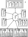
- FIG. 1 shows an example system 100 for injecting data (e.g., one or more pulse signals) into a network.
- the system 100 may be configured to inject data into a network 105 and send information indicative of the injected data to a device (e.g., devices 102A-102B, network devices 116A-116D, computing device 104, etc.) connected to the network 105.
- the system 100 may be configured to provide services, such as network-related services, to a device.
- the network and system may comprise a plurality of devices 102A-102B in communication with a plurality of network devices 116A-116D and/or a computing device 104, such as a server, for example, via network 105.
- the computing device 104 may be disposed locally or remotely relative to the devices 102A-102B and the network devices 116A-116D.
- the devices 102A-102B, network devices 116A-116D, and the computing device 104 can be in communication via a private and/or public network 105 such as the Internet or a local area network (LAN).
- a private and/or public network 105 such as the Internet or a local area network (LAN).
- LAN local area network
- Other forms of communications can be used such as wired and wireless telecommunication channels, for example.
- the devices 102A-102B may comprise one or more user devices.
- the user devices may comprise electronic devices such as computers, smartphones, laptops, tablets, set top boxes, display devices, or other devices capable of communicating with the network devices 116A-116D and/or the computing device 104.
- the user devices may further comprise devices such as media devices, VoIP devices, routers, printers, WiFi speakers, security cameras, or smart assistant devices (e.g. Alexa, Nest, Ring, etc.).
- the devices 102A-102B may comprise communication elements 106A-106B for providing an interface to a user to interact with the devices 102A-102B and/or the computing device 104.
- the communication elements 106A-106B can be any interface for presenting and/or receiving information to/from the user, such as user feedback.
- An example interface may be a communication interface such as a web browser (e.g., Internet Explorer ® , Mozilla Firefox ® , Google Chrome ® , Safari°, or the like).
- Other software, hardware, and/or interfaces can be used to provide communication between the user and one or more of the devices 102A-102B and the network devices 116A-116D and/or the computing device 104.
- the communication elements 106A-106B may request or query various files from a local source and/or a remote source.
- the communication elements 106A-106B may transmit data to a local or remote device such as the network devices 116A-116D and/or the computing device 104.
- the devices 102A-102B may be associated with user identifiers or device identifiers 108A-108.
- the device identifiers 108A-108B may be any identifier, token, character, string, or the like, for differentiating one user or user device (e.g., devices 102A-102B) from another user or user device.
- the device identifiers 108A-108B may identify a user or user device as belonging to a particular class of users or user devices.
- the device identifiers 108A-108B may comprise information relating to the devices 102A-102B such as a manufacturer, a model or type of device, a service provider associated with the devices 102A-102B, a state of the devices 102A-102B, a locator, and/or a label or classifier. Other information can be represented by the device identifiers 108A-108B.
- the device identifiers 108A-108B may comprise address element 110A-110B and service element 112A-112B.
- the address elements 110A-110B may comprise or provide an Internet protocol address, a network address, a media access control (MAC) address, international mobile equipment identity (IMEI) number, international portable equipment identity (IPEI) number, an Internet address, or the like.
- the address elements 110A-110B may be relied upon to establish a communication session between the devices 102A-102B and the network devices 116A-116D and/or the computing device 104 or other devices and/or networks.
- the address elements 110A-110B can be used as an identifier or locator of the devices 102A-102B.
- the address elements 110A-110B can be persistent for a particular network.
- the service elements 112A-112B may comprise an identification of the service providers associated with the devices 102A-102B, with the class of devices 102A-102B, and/or with a particular network 105 with which the devices 102A-102B are currently accessing services associated with the service providers.
- the class of the devices 102A-102B may be related to a type of device, capability of device, type of service being provided, and/or a level of service (e.g., business class, service tier, service package, etc.).
- the service elements 112A-112B may comprise information relating to or provided by a communication service provider (e.g., Internet service provider) that is providing or enabling data flow such as communication services to the devices 102A-102B.
- a communication service provider e.g., Internet service provider
- the service elements 112A-112B may comprise information relating to a preferred service provider for one or more particular services relating to the devices 102A-102B.
- the address elements 110A-110B can be used to identify or retrieve data from the service elements 112A-112B, or vice versa.
- one or more of the address elements 110A-110B and the service elements 112A-112B may be stored remotely from the devices 102A-102B and retrieved by one or more devices such as the devices 102A-102B and the computing device 104. Other information may be represented by the service elements 112A-112B.
- the computing device 104 may comprise a server for communicating with the devices 102A-102B and/or the network devices 116A-116D via network 105.
- the computing device 104 may communicate with the devices 102A-102B for providing data and/or services.
- the computing device 104 may provide services, such as network (e.g., Internet) connectivity, network printing, media management (e.g., media server), content services, streaming services, broadband services, or other network-related services.
- the computing device 104 may allow the devices 102A-102B to interact with remote resources, such as data, devices, and files.
- the computing device 104 may be configured as (or disposed at) a central location (e.g., a headend, or processing facility), which may receive content (e.g., data, input programming) from multiple sources.
- the computing device 104 may combine the content from the multiple sources and may distribute the content to user (e.g., subscriber) locations via a distribution system.
- the computing device 104 may be configured to manage the communication between the devices 102A-102B and a database 114 for sending and receiving data therebetween.
- the database 114 may store a plurality of files (e.g., web pages), user identifiers or records, or other information.
- the devices 102A-102B may request and/or retrieve a file from the database 114.
- the database 114 may store information relating to the devices 102A-102B such as the address element 110 and/or the service element 112.
- the computing device 104 may obtain the device identifiers 108A-108B from the devices 102A-102B and retrieve information from the database 114 such as the address elements 110A-110B and/or the service elements 112A-112B.
- the computing device 104 may obtain the address elements 110A-110B from the devices 102A-102B and may retrieve the service elements 112A-112B from the database 114, or vice versa. Any information may be stored in and retrieved from the database 114.
- the database 114 may be disposed remotely from the computing device 104 and accessed via direct or indirect connection.
- the database 114 may be integrated with the computing device 104 or some other device or system.
- One or more of the network devices 116A-116D may be configured to facilitate the connection of a device, such as the user device 102A-102B, to the network 105.
- the network devices 116A-116D may be configured as wireless access points (WAPs).
- the network devices 116A-116D may be configured to allow one or more wireless devices to connect to a wired and/or wireless network using Wi-Fi, Bluetooth ® , Zigbee ® , or any desired method or standard.
- the network devices 116A-116D may comprise identifiers 118A-118D.
- one or more identifiers can be or relate to an Internet Protocol (IP) Address IPV4/IPV6 or a media access control address (MAC address) or the like.
- IP Internet Protocol
- MAC address media access control address
- the identifiers 118A-118D may be unique identifiers for facilitating communications on the physical network segment.
- Each of the network devices 116A-116D may comprise an identifier 118 that is distinct.
- the identifiers 118A-118D may be associated with a physical location of the network devices 116A-116D.
- One or more devices may be configured to establish a network connection with at least one other device (e.g., devices 102A-102B, network devices 116A-116D, the computing devices 104, etc.) via network 105.
- the network connection may comprise an Internet connection comprising a plurality of independent data streams.
- each independent data stream may comprise a plurality of data packets, wherein each data packet may be individually encrypted.
- the plurality of independent data streams may comprise one or more of data injected into the network, one or more media streams, one or more video streams, one or more audio streams, one or more data streams, or any combination thereof.
- the network connection may comprise an encrypted connection such as a Quick UDP Internet Connection (QUIC) connection, wherein each data packet of the plurality data packets may be individually encrypted.
- QUIC Quick UDP Internet Connection
- the use of such encryption methods as QUIC increases the difficulty for third party monitoring of the data packets.
- the QUIC protocol provides the use of only a single bit assigned for end-to-end delivery testing and observation, wherein all other transport header data is encrypted.
- the devices connected to the network 105 may be configured to inject data (e.g., a pulse signal) into the network 105 and send information indicative of the injected data to a monitoring device to enable the monitoring device to determine one or more characteristics of the network.
- data e.g., a pulse signal
- the data injected into the network may be used in order to track one or more data packets of the plurality of individually encrypted data packets as the one or more data packets are transmitted throughout the network 105.
- the monitoring device may determine one or more characteristics of the network by correlating the information indicative of the injected data with an effect caused to the network by the injected data. For example, unencrypted data injected into the network may result in one or more of the plurality of individually encrypted data packets to increase in a data size.
- the monitoring device may identify a pattern of the plurality of individually encrypted data packets based on the information indicative of the injected data. For example, the monitoring device may determine that the data size of one or more of the plurality of individually encrypted data packets appear in the network according to a particular signal pattern (e.g., pulse signal according to one or more attributes) and correlates with the information indicative of the injected data. Thus, the monitoring device may identify the data injected into the network based on the correlation of the information indicative of the injected data with the effect caused to the network by the injected data. Based on the identification of the data injected into the network, the monitoring device may determine the one or more characteristics of the network. The one or more characteristics of the network may comprise one or more of a network backlog, network congestion, or data packet loss.
- a particular signal pattern e.g., pulse signal according to one or more attributes
- the injected data may comprise null data packets that may be injected into the network as a pulse signal comprising one or more attributes.
- the one or more attributes may comprise one or more of a predetermined data size, a predetermined data frequency, a predetermined data pattern, a random data pattern, or a predetermined data injection interval.
- the monitoring device may analyze the network based on identifying the injected data to determine one or more characteristics of the network over a period of time. The monitoring device may determine one or more characteristics of the network during one or more time segments and correlate the one or more characteristics during each time segment of the one or more time segments to determine how the network behaves and varies over time.
- the one or more time segments may comprise one or more of one or more contiguous time segments, one or more continuous time segments, or one or more discrete time segments.
- the devices 102A-102B, the network devices 116A-116D, the computing devices 104, or any combination thereof may be configured to inject the data into the network and send the information indicative of the injected data to the monitoring device.
- the devices 102A-102B, the network devices 116A-116D, the computing devices 104, or any combination thereof may be configured to act as a monitoring device and receive the information indicative of the injected data to determine the one or more characteristics of the network.
- the one or more characteristics of the network may be used to determine that one of the independent data streams of the network has reached a point in the network that is subject to network congestion or is experiencing data packet loss between two points of the network.
- a network connection may be established between device 102A and device 102B, wherein at least one independent data stream of the plurality of independent data streams may be routed via network device 116A.
- Device 102B may determine, based on identifying data injected into the network by device 102A, that network device 116A is experiencing congestion.
- device 102B may communicate the network issue to device 102A, wherein device 102A may cause the at least one independent data stream to re-route via network device 116B to device 102B.
- Device 102A may further inject data into the data stream directed towards device 102B for device 102B to determine/confirm that there are no issues (e.g., network backlog, network congestion, or data packet loss) with routing the at least one independent data stream via network device 116B.
- issues e.g., network backlog, network congestion, or data packet loss
- two devices may communicate bi-directionally between each other via the network (e.g., QUIC connection, Internet connection).
- the network e.g., QUIC connection, Internet connection.
- device 102A may inject data into the network to communicate one or more characteristics associated with the network to device 102B.
- Device 102B may provide a communication, in response to the injected data, by injecting data of its own into the network directed towards device 102A.
- a device e.g., devices 102A-102B, network devices 116A-116D, computing device 104, etc.
- monitoring the network may identify the data injected into the network to determine one or more characteristics of at least one independent data stream of the plurality of independent data streams of the network.
- the monitoring device may "subtract" the signature of the injected data from the collected telemetry of a network connection (e.g., the total amount of data of the network connection) to determine the one or more characteristics of the at least one independent data stream.
- the one or more characteristics of the at least one independent data stream may comprise one or more of a bit rate of the at least one independent data stream or a bandwidth requirement of the at least one independent data stream.
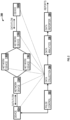
- FIG. 2 shows an example network 200 for the data flow of the data packets in the network 200 between the two devices.
- device 102A may establish a network connection with device 102B.
- the network connection may comprise a plurality of independent data streams.
- Each independent data stream of the plurality of independent data streams may comprise a plurality of data packets.
- the plurality of independent data streams may comprise one or more of data injected into the network, one or more media streams, one or more video streams, one or more audio streams, one or more data streams, or any combination thereof.
- the network connection may comprise an encrypted connection, such as a QUIC connection, wherein each data packet of the plurality of data packets may be individually encrypted, and thus, increasing the difficulty for third party monitoring of the data packets.
- QUIC connection such as a QUIC connection
- device 102A may establish a network connection wherein at least some of the data packets of at least one of the independent data streams may be routed via network device 116A, network device 116B, and network device 116D before reaching device 102B. Furthermore, at least some of the data packets of at least one other independent data stream may be routed via network device 116A, network device 116C, and network device 116D before reaching device 102B.
- Devices 102A and 102B may be configured to communicate one or more characteristics of the network connection to each other by injecting data (e.g., pulse signal) into the network connection and sending information indicative of the injected data to each other to enable the other device to determine the one or more characteristics of the network connection.
- data e.g., pulse signal
- a pulse control device 202 may be configured to cause at least one of the devices 102A-102B to inject data into the network connection.
- the pulse control device 202 may be configured to create and manage data events that will create the data to be injected into the network connection.
- the pulse control device 202 may be configured to define a new pulse event and pulse data wave form, set the pulse event data size, set the pulse event data content, create a new pulse event queue, create the pulse event instance, add the pulse event instance to the signal queue scheduled for a time X, process the pulse event queue, stop the pulse event queue, and get the pulse event history report.
- a data collection device 204 may be configured to receive information indicative of the injected data from the pulse control device 202 so that the data collection device 204 may identify the injected data (e.g., pulse signal).
- the data collection device 204 may be configured as one or more monitoring devices at different collection points in the network, such as the dotted lines shown in FIG. 2 , for example.
- the data collection device 204 may be configured to send the injected data characteristics (e.g., time, data events, etc.) to a data analytics device 206 to permit the data analytics device 206 to identify the injected data and remove the injected data's signature from the collected telemetry of the network connection to permit analysis of the network data without the injected data.
- the data analytics device 206 may determine a bit rate of one or more of the data streams of the network connection.
- a data reporter 208 may then report the one or more characteristics of the network connection determined by the data analytics device 206 to device 102A and/or device 102B.
- the use of a pulse control device 202, a data collection device 204, a data analytics device 206, and a data reporter device 208 as separate devices is merely one example of injecting data into the network connection to determine one or more characteristics of the network connection.
- the devices may be combined into a single device, or the processes performed by each device may be performed by each of the devices 102A-102B and the network devices 116A-116D individually, or a combination thereof.
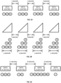
- FIGS. 3A-C and FIG. 4 show example data that may be injected into the network connection.
- the injected data may comprise null data packets that may be injected into the network as a pulse signal comprising one or more attributes.
- the one or more attributes may comprise one or more of a predetermined data size, a predetermined data frequency, predetermined data pattern, a random data pattern, or a predetermined data injection interval.
- FIG. 3A shows a signal containing fixed data amounts X bytes sent at fixed time t intervals.
- FIG. 3B shows a saw tooth signal, wherein data may start at one byte and increase at y bytes per second fraction for q seconds repeated every t seconds.
- 3C shows a signal containing random bytes at random intervals.
- the actual random data amounts and delays may be reported out to the telemetry system (e.g., devices 102A-102B, network devices 116A-116D, computing device 104, etc.) so that they may be identified in the collected telemetry data. This also permits them to be processed out of the collected raw telemetry of the network connection.
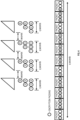
- FIG. 4 shows an example of a saw tooth signal as it may be encrypted in a QUIC network connection. The use of such encryption methods as QUIC increases the difficulty for third party monitoring of the data packets.
- the monitoring may recognize a QUIC connection has been injected with data by recognizing the pattern of the injected data.
- the monitoring device may receive information indicative of the injected data and identify an effect cause by the injected data to the QUIC network connection.
- the monitoring device may identify a data waveform or pattern of the QUIC network connection that may be correlated with the information indicative of the data that was injected into the QUIC network connection. Based on correlating the waveform or pattern of the QUIC network connection with the information indicative of the injected data, the monitoring device may identify the injected data.
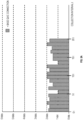
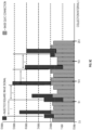
- FIGS 5A-5C show an example of how the injected data may affect the network connection at several data collection points.
- FIG. 5A shows an example network connection that is monitored according to collection interval t.
- a monitoring device may observe the network connection at multiple intervals, wherein the network connection never exceeds 2 kbits at each monitoring interval.
- data may be injected into the network connection.
- the injected data may comprise a square wave signal comprising 3.1 kbits at a frequency of 3t.
- a monitoring device may identify the injected data based on observing the irregularities in the network connection. Over time, the monitoring device may recognize the injected data based on the waveform or pattern of the injected data.
- the square wave may be injected at a frequency f, wherein f/t comprises a non-whole number. Since frequency f may not be an even multiple of t, the injected signal may span multiple collection intervals. Thus, the injected signal/data, over time, may be distinctly recognizable by a device monitoring the network connection.
- the monitoring device may be configured to receive information indicative of the injected data. For example, the monitoring device may receive information indicating that the injected data comprises a square wave signal comprising 3.1 kbits at the frequency f.
- the monitoring device may determine, over time, an effect caused to the network connection based on the information indicative of the injected data.
- the monitoring device may detect the pattern of the data peaks of the network connection at each data collection time t and determine that the network connection includes injected data.
- the monitoring device may correlate the effect caused to the network connection by the injected data with the information indicative of the injected data to identify the injected data.
- the monitoring device may remove the injected data's signature from the collected telemetry of the network connection to analyze the network data without the injected data. For example, by removing the injected data's signature, the monitoring device may determine a bit rate of one or more of the data streams of the network connection.
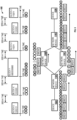
- FIG. 6 shows an example data flow scenario 600 of the data packets in a network connection.
- device 102A may establish a network connection with device 102B.
- the network connection may comprise a plurality of independent data streams, wherein each independent data stream of the plurality of independent data streams may comprise a plurality of data packets.
- the network connection may comprise an encrypted connection, such as a QUIC connection, wherein each data packet of the plurality of data packets may be individually encrypted.
- the encryption of each data packet increases the difficulty for third party monitoring of the data packets. For example, FIG.
- FIG. 6 shows that data packets 1, 2, and 3 associated with Block X are sent at a first time, encryption data packets associated with Block X are sent at a second time, data packets 7, 8, 9, A, and B associated with Block Y are sent at a third time, data packets C and D associated with Block Z are sent at a fourth time, data packets E, F, and G associated with Block X are sent at a fifth time, and data packets H and I associated with Block Z are sent at a sixth time.
- Device 102A may establish a network connection wherein at least some of the data packets may be routed via network device 116A, network device 116B, and network device 116D, while at least some of the data packets may be routed via network device 116A, network device 116C, and network device 116D.
- data packets G, E, D, C, 3, 2, and 1 and the encryption padding data packets are routed via network device 116B, while data packets I, H, F, B, A, 9, 8, and 7 are routed via network device 116C.
- Device 102B may inject data into the network connection and send information indicative of the injected data to device 102B, wherein device 102B may identify the injected data, based on the information indicative of the injected data, to determine that network device 116B is the point in the network connection experiencing issues causing data packet loss or network backlog/congestion. As a result, device 102B may communicate this issue to device 102A, wherein device 102A may cause the data packets to be re-routed via network device 116C to device 102B.
- a monitoring device may monitor the data routed via network device 116B, identify the injected data, based on the information indicative of the injected data, and determine the issues associated with network device 116B and report the issues to device 102A.
- FIG. 7 shows an example method 700 for determining one or more characteristics of a network based on data injected into the network.
- Method 700 may be implemented by devices 102A-102B, network devices 116A-116D, computing device 104, or any combination thereof.
- information indicative of data injected into a network may be received.
- the injected data may comprise a pulse signal having one or more attributes.
- the one or more attributes may comprise one or more of a predetermined data size, a predetermined data frequency, a predetermined data pattern, a random data pattern, a predetermined data injection interval, or any combination thereof.
- the information indicative of the injected data may comprise the one or more attributes of the injected data.
- the network may comprise a plurality of data streams associated with a plurality of individually encrypted data packets.
- the plurality of data streams may comprise one or more of the injected data, one or more media streams, one or more video streams, one or more audio streams, or one or more data streams.
- the injected data may be identified based on a correlation of the information indicative of the injected data with an effect caused to the network by the injected data.
- the initial data injected into the network may comprise unencrypted data.
- the unencrypted data injected into the network may result in one or more of the plurality of individually encrypted data packets to increase in a data size.
- a device monitoring the network may identify a pattern of the plurality of individually encrypted data packets based on the information indicative of the injected data.
- the monitoring device may determine that a data size of one or more of the plurality of individually encrypted data packets appear in the network according to a particular signal pattern (e.g., the pulse signal according to the one or more attributes) and correlates with the information indicative of the injected data.
- the monitoring device may identify the data injected into the network based on the correlation of the information indicative of the injected data with the effect caused to the network by the injected data.
- one or more characteristics of the network may be determined based on the identification of the data injected into the network.
- the one or more characteristics of the network may comprise one or more of a network backlog, network congestion, or data packet loss.
- the one or more characteristics may be used to determine that one of the data streams of the network is being routed via a device that is experiencing network congestion.
- a monitoring device may identify this issue and notify the device sending data through the network so that the device may cause the independent data stream to re-route via a second device.
- a monitoring device may analyze the network based on identifying the injected data to determine one or more characteristics of the network over a period of time.
- the monitoring device may determine one or more characteristics of the network during one or more time segments and correlate the one or more characteristics during each time segment of the one or more time segments to determine how the network behaves and varies over time.
- the one or more time segments may comprise one or more of one or more contiguous time segments, one or more continuous time segments, or one or more discrete time segments.
- FIG. 8 shows an example method 800 for determining one or more characteristics of a network based on data injected into the network.
- Method 800 may be implemented by devices 102A-102B, network devices 116A-116D, computing device 104, or any combination thereof.
- a plurality of data streams may be caused to route via a first network device.
- the plurality of data streams may comprise one or more of first data injected into the network, one or more media streams, one or more video streams, one or more audio streams, or one or more data streams.
- the network may comprise the plurality of data streams, wherein the plurality of data streams may be associated with a plurality of individually encrypted data packets.
- first data may be injected into the network.
- the injected first data may comprise a pulse signal having one or more attributes.
- the one or more attributes may comprise one or more of a predetermined data size, a predetermined data frequency, a predetermined data pattern, a random data pattern, a predetermined data injection interval, or any combination thereof.
- the injected first data may comprise unencrypted data.
- the unencrypted data injected into the network may result in one or more of the plurality of individually encrypted data packets to increase in a data size.
- the pattern of the increased data sizes of the one or more individually encrypted data packets may be correlated with information indicative of the injected first data in order to identify the injected first data.
- information indicative of the injected first data may be sent into the network.
- the information indicative of the injected first data may be used to identify the first data injected into the network.
- the information indicative of the injected first data may comprise the one or more attributes of the injected first data.
- the injection of the first data into the network may cause an effect to the network that may be identified by a device monitoring the network by correlating the effect with the information indicative of the first data.
- the monitoring device may identify a pattern of the plurality of individually encrypted data packets based on the information indicative of the injected first data.
- the monitoring device may determine that a data size of one or more of the plurality of individually encrypted data packets appear in the network according to a particular signal pattern (e.g., the pulse signal according to the one or more attributes) and correlates with the information indicative of the injected first data.
- the monitoring device may identify the first data injected into the network based on the correlation of the information indicative of the injected first data with the effect caused to the network by the injected first data.
- a monitoring device may be configured to receive the information indicative of the injected first data.
- the monitoring device may be configured to monitor the network and correlate an effect caused to the network based on the injected first data with the information indicative of the injected first data.
- the unencrypted data injected into the network may result in one or more of the plurality of individually encrypted data packets to increase in a data size.
- the monitoring device may determine that a data size of one or more of the plurality of individually encrypted data packets appear in the network according to a particular signal pattern (e.g., the pulse signal according to the one or more attributes) and correlates with the information indicative of the injected first data.
- the monitoring device may identify the first data injected into the network based on the correlation of the information indicative of the injected first data with the effect caused to the network by the injected first data. Based on the identification of the injected first data, the monitoring device may determine one or more characteristics of the network and send the characteristic data to a device that sent the plurality of data streams.
- the one or more characteristics may comprise one or more of a network backlog, network congestion, or data packet loss.
- a device that sent the plurality of data streams may determine from the one or more characteristics that the first network device may be experiencing network congestion. The device may then cause the at least one independent data stream to be re-routed via the second network device.
- second data may be injected into the network in order to determine if there any issues with re-routing the at least one data stream via the second network device. For example, after the at least one data stream is re-routed via the second network device, a device that established the network may inject the second data based on the re-routing of the at least one data stream to confirm whether or not the new route, via the second network device, is experiencing any network congestion or data packet loss.
- the injected second data may comprise a pulse signal having one or more attributes.
- the one or more attributes may comprise one or more of a predetermined data size, a predetermined data frequency, a predetermined data pattern, a random data pattern, a predetermined data injection interval, or any combination thereof.
- the injected second data may comprise unencrypted data.
- the unencrypted data injected into the network may result in one or more of the plurality of individually encrypted data packets to increase in a data size.
- the pattern of the increased data sizes of the one or more individually encrypted data packets may be correlated with information indicative of the injected second data in order to identify the injected second data.
- the information indicative of the injected second data may be sent.
- the information indicative of the injected second data may comprise the one or more attributes of the injected second data.
- the injection of the second data into the network may cause an effect to the network that may be identified by a device monitoring the network by correlating the effect with the information indicative of the second data.
- the monitoring device may identify a pattern of the plurality of individually encrypted data packets based on the information indicative of the injected second data.
- the monitoring device may determine that a data size of one or more of the plurality of individually encrypted data packets appear in the network according to a particular signal pattern (e.g., the pulse signal according to the one or more attributes) and correlates with the information indicative of the injected second data.
- the monitoring device may identify the second data injected into the network based on the correlation of the information indicative of the injected second data with the effect caused to the network by the injected first data.
- One or more characteristics of the network associated with the at least one data stream being re-routed via the second network device may be received.
- a monitoring device may receive the information indicative of the injected second data.
- the monitor device may correlate an effect caused to the network based on the injected second data with the information indicative of the injected second data.
- the unencrypted data injected into the network may result in one or more of the plurality of individually encrypted data packets to increase in a data size.
- the monitoring device may determine that a data size of one or more of the plurality of individually encrypted data packets appear in the network according to a particular signal pattern (e.g., the pulse signal according to the one or more attributes) and correlates with the information indicative of the injected second data.
- the monitoring device may identify the second data injected into the network based on the correlation of the information indicative of the injected second data with the effect caused to the network by the injected second data. Based on the identifying the injected second data, the monitoring device may determine one or more characteristics of the network and send the characteristic data to a device that sent the plurality of data streams. As an example, the one or more characteristics may indicate, or confirm, whether or not the new route, via the second network device, is experiencing any network congestion or data packet loss.
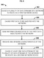
- FIG. 9 shows an example method 900 for determining one or more characteristics of a network based on data injected into the network.
- Method 900 may be implemented by devices 102A-102B, network devices 116A-116D, computing device 104, or any combination thereof.
- first data may be injected into a network.
- the network may comprise a plurality of data streams, wherein the plurality of data streams may be associated with a plurality of individually encrypted data packets.
- the injected first data may comprise a pulse signal having one or more attributes.
- the one or more attributes may comprise one or more of a predetermined data size, a predetermined data frequency, a predetermined data pattern, a random data pattern, a predetermined data injection interval, or any combination thereof.
- the injected first data may comprise unencrypted data.
- the unencrypted data injected into the network may result in one or more of the plurality of individually encrypted data packets to increase in a data size.
- the pattern of the increased data sizes of the one or more individually encrypted data packets may be correlated with information indicative of the injected first data in order to identify the injected first data.
- information indicative of the injected first data may be sent.
- the information indicative of the injected first data may be used to identify the first data injected into the network.
- the information indicative of the injected first data may comprise the one or more attributes of the injected first data.
- the injection of the first data into the network may cause an effect to the network that may be identified by a device monitoring the network by correlating the effect with the information indicative of the first data.
- the monitoring device may identify a pattern of the plurality of individually encrypted data packets based on the information indicative of the injected first data.
- the monitoring device may determine that a data size of one or more of the plurality of individually encrypted data packets appear in the network according to a particular signal pattern (e.g., the pulse signal according to the one or more attributes) and correlates with the information indicative of the injected first data.
- the monitoring device may identify the first data injected into the network based on the correlation of the information indicative of the injected first data with the effect caused to the network by the injected first data.
- information indicative of second data injected into the network may be received.
- the information indicative of the injected second data may comprise one or more attributes (e.g., data size, data frequency, data pattern, and/or data injection interval) of the injected second data.
- a monitoring device may be configured to receive the information indicative of the injected first data.
- the monitoring device may be configured to monitor the network and correlate an effect caused to the network based on the injected first data with the information indicative of the injected first data.
- the unencrypted data injected into the network may result in one or more of the plurality of individually encrypted data packets to increase in a data size.
- the monitoring device may determine that a data size of one or more of the plurality of individually encrypted data packets appear in the network according to a particular signal pattern (e.g., the pulse signal according to the one or more attributes) and correlates with the information indicative of the injected first data.
- the monitoring device may identify the first data injected into the network based on the correlation of the information indicative of the injected first data with the effect caused to the network by the injected first data.
- the monitoring device may determine one or more characteristics of the network. Based on the one or more characteristics, the monitoring device may inject second data into the network and send information indicative of second data injected into the network to a device that may have injected the first data into the network.
- two devices may bi-directionally communicate with each other via the network in order to communicate one or more characteristics of the network, such as, for example, network backlog, network congestion, or data packet loss.
- the injected second data may be identified based on a correlation of the information indicative of the injected second data and an effect caused to the network by the injected second data.
- the initial data injected into the network may comprise unencrypted data.
- the unencrypted data injected into the network may result in one or more of the plurality of individually encrypted data packets to increase in a data size.
- a device monitoring the network may identify a pattern of the plurality of individually encrypted data packets based on the information indicative of the injected data.
- the monitoring device may determine that a data size of one or more of the plurality of individually encrypted data packets appear in the network according to a particular signal pattern (e.g., the pulse signal according to the one or more attributes) and correlates with the information indicative of the injected second data.
- the monitoring device may identify the second data injected into the network based on the correlation of the information indicative of the injected second data with the effect caused to the network by the injected second data.
- one or more characteristics of the network may be determined based on the identification of the second data injected into the network.
- the one or more characteristics of the network may comprise one or more of a network backlog, network congestion, or data packet loss.
- the one or more characteristics may be used to determine that one of the data streams of the plurality of data streams is being routed via a device that is experiencing network congestion.
- a monitoring device may identify this issue and notify the device sending data through the network so that the device may cause the data stream to re-route via a second device.
- FIG. 10 shows an example method 1000 for defining the data to be injected into a network based on one or more characteristics of the network to be monitored.
- Method 1000 may be implemented by devices 102A-102B, network devices 116A-116D, computing device 104, or any combination thereof.
- one or more characteristics of a network to be monitored may be determined.
- the one or more characteristics of the network to be monitored may comprise one or more of a network backlog, network congestion, or data packet loss.
- the network may comprise a plurality of data streams associated with a plurality of individually encrypted data packets.
- the plurality of data streams may comprise one or more of injected data, one or more media streams, one or more video streams, one or more audio streams, or one or more data streams.
- a step 1004 one or more attributes of data to be injected into injected into the network may be determined based on the one or more characteristics of the network to be monitored.
- the one or more attributes may comprise one or more of a predetermined data size, a predetermined data frequency, or a predetermined data injection interval.
- the data to be injected into the network may be defined based on the one or more characteristics of the network to be monitored.
- the injected data may be defined in a manner to improve the accuracy of determining the one or more characteristics to be monitored.
- the injected data may be defined as a square wave (e.g., pulse signal) injected at a specified frequency.
- the network may be monitored at an interval every t times associated with the frequency.
- the frequency may not comprise an even multiple of t, and thus, the injected data may span multiple collection intervals. The result is that the injected data, over time, may be distinctly recognizable by a device monitoring the network.
- the data may be injected into the network.
- the data injected into the network may be defined according to the one or more attributes.
- the data may comprise a pulse signal.
- information indicative of the injected data may be sent.
- the information indicative of the injected data may comprise the one or more attributes of the injected data.
- the information indicative of the injected data may be used by a monitoring device to identify the data injected into the network.
- the injection of the data into the network may cause an effect to the network that may be identified by a device monitoring the network by correlating the effect with the information indicative of the data.
- the monitoring device may identify a pattern of the plurality of individually encrypted data packets based on the information indicative of the injected data.
- the monitoring device may determine that a data size of one or more of the plurality of individually encrypted data packets appear in the network according to a particular signal pattern (e.g., the pulse signal according to the one or more attributes) and correlates with the information indicative of the injected first data.
- the monitoring device may identify the data injected into the network based on the correlation of the information indicative of the injected data with the effect caused to the network by the injected data.
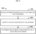
- FIG. 11 shows an example method 1100 for determining one or more characteristics of a network based on data injected into the network.
- Method 1100 may be implemented by devices 102A-102B, network devices 116A-116D, computing device 104, or any combination thereof.
- information indicative of data injected into the network may be received.
- the injected data may comprise a pulse signal having one or more attributes.
- the one or more attributes may comprise one or more of a predetermined data size, a predetermined data frequency, a predetermined data pattern, a random data pattern, a predetermined data injection interval, or any combination thereof.
- the information indicative of the injected data may comprise the one or more attributes of the injected data.
- the network may comprise a plurality of data streams associated with a plurality of individually encrypted data packets.
- the plurality of data streams may comprise one or more of the injected data, one or more media streams, one or more video streams, one or more audio streams, or one or more data streams.
- the injected data may be identified based on a correlation of the information indicative of the injected data with an effect caused to the network by the injected data.
- the initial data injected into the network may comprise unencrypted data.
- the unencrypted data injected into the network may result in one or more of the plurality of individually encrypted data packets to increase in a data size.
- a device monitoring the network may identify a pattern of the plurality of individually encrypted data packets based on the information indicative of the injected data.
- the monitoring device may determine that a data size of one or more of the plurality of individually encrypted data packets appear in the network according to a particular signal pattern (e.g., the pulse signal according to the one or more attributes) and correlates with the information indicative of the injected data.
- the monitoring device may identify the data injected into the network based on the correlation of the information indicative of the injected data with the effect caused to the network by the injected data.
- one or more characteristics of at least one data stream of the plurality of data streams may be determined based on the identification of the data injected into the network.
- the one or more characteristics of the at least one data stream may comprise one or more of a bit rate of the at least one data stream, or a bandwidth requirement of the at least one data stream.
- a monitoring device may compare the injected data to the data of the network. For example, the monitoring device may "subtract" the signature of the injected data from the collected telemetry of the network (e.g., the total amount of data of the network, or network connection) to determine the one or more characteristics of the at least one data stream.
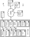
- FIG. 12 is a block diagram illustrating an example operating environment 1200 for performing the disclosed methods.
- This operating environment 1200 is only an example of an operating environment and is not intended to suggest any limitation as to the scope of use or functionality of operating environment architecture. Neither should the operating environment 1200 be interpreted as having any dependency or requirement relating to any one or combination of components illustrated in the operating environment 1200.
- the present methods and systems can be operational with numerous other general purpose or special purpose computing system environments or configurations.
- Examples of well-known computing systems, environments, and/or configurations that can be suitable for use with the systems and methods comprise, but are not limited to, personal computers, server computers, laptop devices, and multiprocessor systems. Additional examples comprise set top boxes, programmable consumer electronics, network PCs, minicomputers, mainframe computers, distributed computing environments that comprise any of the above systems or devices, and the like.
- the processing of the disclosed methods and systems can be performed by software components.
- the disclosed systems and methods can be described in the general context of computer-executable instructions, such as program modules, being executed by one or more computers or other devices.
- program modules comprise computer code, routines, programs, objects, components, data structures, and/or the like that perform particular tasks or implement particular abstract data types.
- the disclosed methods can also be practiced in grid-based and distributed computing environments where tasks are performed by remote processing devices that are linked through a communications network.
- program modules can be located in local and/or remote computer storage media such as memory storage devices.
- the computer 1201 can comprise one or more components, such as one or more processors 1203, a system memory 1212, and a bus 1213 that couples various components of the computer 1201 comprising the one or more processors 1203 to the system memory 1212.
- the system can utilize parallel computing.
- the bus 1213 can comprise one or more of several possible types of bus structures, such as a memory bus, memory controller, a peripheral bus, an accelerated graphics port, or local bus using any of a variety of bus architectures.
- bus architectures can comprise an Industry Standard Architecture (ISA) bus, a Micro Channel Architecture (MCA) bus, an Enhanced ISA (EISA) bus, a Video Electronics Standards Association (VESA) local bus, an Accelerated Graphics Port (AGP) bus, and a Peripheral Component Interconnects (PCI), a PCI-Express bus, a Personal Computer Memory Card Industry Association (PCMCIA), Universal Serial Bus (USB) and the like.
- ISA Industry Standard Architecture
- MCA Micro Channel Architecture
- EISA Enhanced ISA
- VESA Video Electronics Standards Association
- AGP Accelerated Graphics Port
- PCI Peripheral Component Interconnects
- PCI-Express PCI-Express
- PCMCIA Personal Computer Memory Card Industry Association
- USB Universal Serial Bus
- the bus 1213, and all buses specified in this description can also be implemented over a wired or wireless network connection and one or more of the components of the computer 1201, such as the one or more processors 1203, a mass storage device 1204, an operating system 1205, pulse signal software 1206, pulse signal data 1207, a network adapter 1208, the system memory 1212, an Input/Output Interface 1210, a display adapter 1209, a display device 1211, and a human machine interface 1202, can be contained within one or more remote computing devices 1214A-1214C at physically separate locations, connected through buses of this form, in effect implementing a fully distributed system.
- the computer 1201 typically comprises a variety of computer readable media.
- computer readable media may be any available media that is accessible by the computer 1201 and comprises, for example and not meant to be limiting, both volatile and non-volatile media, removable and non-removable media.
- the system memory 1212 can comprise computer readable media in the form of volatile memory, such as random access memory (RAM), and/or non-volatile memory, such as read only memory (ROM).
- RAM random access memory
- ROM read only memory
- the system memory 1212 typically can comprise data such as the pulse signal data 1207 and/or program modules such as the operating system 1205 and the pulse signal software 1206 that are accessible to and/or are operated on by the one or more processors 1203.
- the computer 1201 may also comprise other removable/non-removable, volatile/non-volatile computer storage media.
- the mass storage device 1204 can provide non-volatile storage of computer code, computer readable instructions, data structures, program modules, and other data for the computer 1201.
- the mass storage device 1204 can be a hard disk, a removable magnetic disk, a removable optical disk, magnetic cassettes or other magnetic storage devices, flash memory cards, CD-ROM, digital versatile disks (DVD) or other optical storage, random access memories (RAM), read only memories (ROM), electrically erasable programmable read-only memory (EEPROM), and the like.
- any number of program modules can be stored on the mass storage device 1204, such as, by way of example, the operating system 1205 and the pulse signal software 1206.
- One or more of the operating system 1205 and the pulse signal software 1206 (or some combination thereof) can comprise elements of the programming and the pulse signal software 1206.
- the pulse signal data 1207 can also be stored on the mass storage device 1204.
- the pulse signal data 1207 can be stored in any of one or more databases known in the art. Examples of such databases comprise, DB2 ® , Microsoft ® Access, Microsoft ® SQL Server, Oracle ® , mySQL, PostgreSQL, and the like.
- the databases can be centralized or distributed across multiple locations within the network 1215.
- the user may enter commands and information into the computer 1201 via an input device (not shown).
- input devices comprise, but are not limited to, a keyboard, pointing device (e.g., a computer mouse, remote control), a microphone, a joystick, a scanner, tactile input devices such as gloves, and other body coverings, motion sensor, and the like
- pointing device e.g., a computer mouse, remote control
- tactile input devices such as gloves, and other body coverings, motion sensor, and the like
- These and other input devices can be connected to the one or more processors 1203 via the human machine interface 1202 that is coupled to the bus 1213, but can be connected by other interface and bus structures, such as a parallel port, game port, an IEEE 1394 Port (also known as a Firewire port), a serial port, a network adapter 1208, and/or a universal serial bus (USB).
- a parallel port e.g., a computer mouse, remote control
- a microphone e.g., a joystick,
- the display device 1211 can also be connected to the bus 1213 via an interface, such as the display adapter 1209. It is contemplated that the computer 1201 can have more than one display adapter 1209 and the computer 1201 can have more than one display device 1211.
- the display device 1211 can be a monitor, an LCD (Liquid Crystal Display), light emitting diode (LED) display, television, smart lens, smart glass, and/ or a projector.
- other output peripheral devices can comprise components such as speakers (not shown) and a printer (not shown) which can be connected to the computer 1201 via an Input/Output Interface 1210. Any step and/or result of the methods can be output in any form to an output device. Such output can be any form of visual representation, comprising, but not limited to, textual, graphical, animation, audio, tactile, and the like.
- the display device 1211 and the computer 1201 can be part of one device, or separate devices.
- the computer 1201 can operate in a networked environment using logical connections to one or more remote computing devices 1214A-1214C.
- a remote computing device 1214A-1214C can be a personal computer, computing station (e.g., workstation), portable computer (e.g., laptop, mobile phone, tablet device), smart device (e.g., smartphone, smart watch, activity tracker, smart apparel, smart accessory), security and/or monitoring device, a server, a router, a network computer, a peer device, edge device or other common network node, and so on.
- Logical connections between the computer 1201 and a remote computing device 1214A-1214C can be made via a network 1215, such as a local area network (LAN) and/or a general wide area network (WAN). Such network connections can be through the network adapter 1208.
- the network adapter 1208 can be implemented in both wired and wireless environments. Such networking environments are conventional and commonplace in dwellings, offices, enterprise-wide computer networks, intranets, and the Internet.
- Computer readable media can comprise “computer storage media” and “communications media.”
- Computer storage media can comprise volatile and non-volatile, removable and non-removable media implemented in any methods or technology for storage of information such as computer readable instructions, data structures, program modules, or other data.
- computer storage media may comprise RAM, ROM, EEPROM, flash memory or other memory technology, CD-ROM, digital versatile disks (DVD) or other optical storage, magnetic cassettes, magnetic tape, magnetic disk storage or other magnetic storage devices, or any other medium which can be used to store the desired information and which can be accessed by a computer.
- the methods and systems can employ artificial intelligence (AI) techniques such as machine learning and iterative learning.
- AI artificial intelligence
- techniques comprise, but are not limited to, expert systems, case based reasoning, Bayesian networks, behavior based AI, neural networks, fuzzy systems, evolutionary computation (e.g. genetic algorithms), swarm intelligence (e.g. ant algorithms), and hybrid intelligent systems (e.g. Expert inference rules generated through a neural network or production rules from statistical learning).
Landscapes
- Engineering & Computer Science (AREA)
- Computer Networks & Wireless Communication (AREA)
- Signal Processing (AREA)
- Environmental & Geological Engineering (AREA)
- Health & Medical Sciences (AREA)
- Cardiology (AREA)
- General Health & Medical Sciences (AREA)
- Data Exchanges In Wide-Area Networks (AREA)
- Selective Calling Equipment (AREA)
- Communication Control (AREA)
Applications Claiming Priority (1)
| Application Number | Priority Date | Filing Date | Title |
|---|---|---|---|
| US18/157,330 US20240250888A1 (en) | 2023-01-20 | 2023-01-20 | Methods and systems for delivering telemetry data |
Publications (1)
| Publication Number | Publication Date |
|---|---|
| EP4404528A1 true EP4404528A1 (de) | 2024-07-24 |
Family
ID=89661933
Family Applications (1)
| Application Number | Title | Priority Date | Filing Date |
|---|---|---|---|
| EP24152851.2A Pending EP4404528A1 (de) | 2023-01-20 | 2024-01-19 | Verfahren und systeme zur bereitstellung von telemetriedaten |
Country Status (3)
| Country | Link |
|---|---|
| US (1) | US20240250888A1 (de) |
| EP (1) | EP4404528A1 (de) |
| CA (1) | CA3226448A1 (de) |
Families Citing this family (1)
| Publication number | Priority date | Publication date | Assignee | Title |
|---|---|---|---|---|
| US20250063342A1 (en) * | 2023-08-16 | 2025-02-20 | Frontier Communications Holdings, Llc | Camouflaging user data |
Citations (4)
| Publication number | Priority date | Publication date | Assignee | Title |
|---|---|---|---|---|
| US6775240B1 (en) * | 1999-09-21 | 2004-08-10 | Lucent Technologies Inc. | System and methods for measuring quality of communications over packet networks |
| US20050060403A1 (en) * | 2003-09-11 | 2005-03-17 | Bernstein David R. | Time-based correlation of non-translative network segments |
| US7583613B2 (en) * | 2005-12-05 | 2009-09-01 | Alcatel Lucent | Method of monitoring the quality of a realtime communication |
| EP3706371A1 (de) * | 2017-12-28 | 2020-09-09 | Huawei Technologies Co., Ltd. | Verfahren und vorrichtung zur messung der qualität eines netzwerks |
Family Cites Families (9)
| Publication number | Priority date | Publication date | Assignee | Title |
|---|---|---|---|---|
| US7408884B2 (en) * | 2003-03-26 | 2008-08-05 | Agilent Technologies, Inc. | Methods and devices for correlating audio sample comparisons and network performance statistics |
| WO2005112345A1 (fr) * | 2004-05-07 | 2005-11-24 | France Telecom | Mesure de performance dans un reseau de transmission de paquets |
| FR2870064A1 (fr) * | 2004-05-07 | 2005-11-11 | France Telecom | Mesure de performance dans un reseau de transmission de paquets |
| EP1743452A1 (de) * | 2004-05-07 | 2007-01-17 | France Telecom | Leistungsmessung in einem paketübertragungsnetz |
| DE102007061312A1 (de) * | 2007-12-19 | 2009-06-25 | Siemens Aktiengesellschaft | Verfahren und Empfangseinrichtung zum Synchronisieren eines paketorientiert empfangenen mit einem gebildeten Tonsignal |
| US8699356B2 (en) * | 2010-12-20 | 2014-04-15 | Deere & Company | Method and system for diagnosing a fault or open circuit in a network |
| US9036472B2 (en) * | 2011-03-15 | 2015-05-19 | Hewlett-Packard Development Company, L.P. | Network switching device for quantifying available service-level capacity of a network for projected network traffic |
| US9094336B2 (en) * | 2013-03-15 | 2015-07-28 | Ixia | Methods, systems, and computer readable media for assisting with the debugging of conditions associated with the processing of test packets by a device under test |
| US11973671B1 (en) * | 2022-11-15 | 2024-04-30 | International Business Machines Corporation | Signal based node relationship identification |
-
2023
- 2023-01-20 US US18/157,330 patent/US20240250888A1/en active Pending
-
2024
- 2024-01-18 CA CA3226448A patent/CA3226448A1/en active Pending
- 2024-01-19 EP EP24152851.2A patent/EP4404528A1/de active Pending
Patent Citations (4)
| Publication number | Priority date | Publication date | Assignee | Title |
|---|---|---|---|---|
| US6775240B1 (en) * | 1999-09-21 | 2004-08-10 | Lucent Technologies Inc. | System and methods for measuring quality of communications over packet networks |
| US20050060403A1 (en) * | 2003-09-11 | 2005-03-17 | Bernstein David R. | Time-based correlation of non-translative network segments |
| US7583613B2 (en) * | 2005-12-05 | 2009-09-01 | Alcatel Lucent | Method of monitoring the quality of a realtime communication |
| EP3706371A1 (de) * | 2017-12-28 | 2020-09-09 | Huawei Technologies Co., Ltd. | Verfahren und vorrichtung zur messung der qualität eines netzwerks |
Also Published As
| Publication number | Publication date |
|---|---|
| CA3226448A1 (en) | 2025-04-08 |
| US20240250888A1 (en) | 2024-07-25 |
Similar Documents
| Publication | Publication Date | Title |
|---|---|---|
| US8619768B2 (en) | Method for dynamic sensor network processing | |
| US20170093648A1 (en) | System and method for assessing streaming video quality of experience in the presence of end-to-end encryption | |
| US11196670B2 (en) | System and method for identifying devices behind network address translators | |
| US9426049B1 (en) | Domain name resolution | |
| US7903657B2 (en) | Method for classifying applications and detecting network abnormality by statistical information of packets and apparatus therefor | |
| RS67684B1 (sr) | Sistemi i postupci za prepoznavanje uređaja | |
| CN107332723B (zh) | 隐蔽通道的检测方法和检测设备 | |
| US9813442B2 (en) | Server grouping system | |
| US20230024018A1 (en) | System, Device, and Method of Classifying Encrypted Network Communications | |
| EP4404528A1 (de) | Verfahren und systeme zur bereitstellung von telemetriedaten | |
| CN114143086A (zh) | 一种Web应用识别方法、装置、电子设备及存储介质 | |
| US20240184857A1 (en) | Device type classification based on usage patterns | |
| CN112769620A (zh) | 一种网络部署方法、设备和计算机可读存储介质 | |
| EP3979558B1 (de) | Anwendungserkennung | |
| US20190289480A1 (en) | Smart Building Sensor Network Fault Diagnostics Platform | |
| EP3718284B1 (de) | Erweiterung von verschlüsselter verkehrsanalytik mit verkehrsflussdaten | |
| EP4087217B1 (de) | Anwendungsnutzungszeitschätzung | |
| CN110225009B (zh) | 一种基于通信行为画像的代理使用者检测方法 | |
| Shaman et al. | User profiling based on application-level using network metadata | |
| US11480955B2 (en) | Smart building sensor network fault diagnostics platform | |
| CN103532937B (zh) | 应用识别验证方法及装置 | |
| CN112866140B (zh) | 业务匹配方法、网关管理平台、网关设备和服务器 | |
| CN106130764B (zh) | 一种监控视频直播间数据服务是否可用的方法及系统 | |
| Naik et al. | I know who you are: a learning framework to profile smartphone users | |
| Meghdouri et al. | Shedding light in the tunnel: Counting flows in encrypted network traffic |
Legal Events
| Date | Code | Title | Description |
|---|---|---|---|
| PUAI | Public reference made under article 153(3) epc to a published international application that has entered the european phase |
Free format text: ORIGINAL CODE: 0009012 |
|
| STAA | Information on the status of an ep patent application or granted ep patent |
Free format text: STATUS: THE APPLICATION HAS BEEN PUBLISHED |
|
| AK | Designated contracting states |
Kind code of ref document: A1 Designated state(s): AL AT BE BG CH CY CZ DE DK EE ES FI FR GB GR HR HU IE IS IT LI LT LU LV MC ME MK MT NL NO PL PT RO RS SE SI SK SM TR |
|
| P01 | Opt-out of the competence of the unified patent court (upc) registered |
Free format text: CASE NUMBER: APP_43419/2024 Effective date: 20240725 |
|
| STAA | Information on the status of an ep patent application or granted ep patent |
Free format text: STATUS: REQUEST FOR EXAMINATION WAS MADE |
|
| 17P | Request for examination filed |
Effective date: 20250124 |
|
| STAA | Information on the status of an ep patent application or granted ep patent |
Free format text: STATUS: EXAMINATION IS IN PROGRESS |
|
| 17Q | First examination report despatched |
Effective date: 20260204 |