EP4404497A2 - Détermination d'un ordre de priorité sur la base de paramètres de transmission en liaison montante - Google Patents
Détermination d'un ordre de priorité sur la base de paramètres de transmission en liaison montante Download PDFInfo
- Publication number
- EP4404497A2 EP4404497A2 EP24181332.8A EP24181332A EP4404497A2 EP 4404497 A2 EP4404497 A2 EP 4404497A2 EP 24181332 A EP24181332 A EP 24181332A EP 4404497 A2 EP4404497 A2 EP 4404497A2
- Authority
- EP
- European Patent Office
- Prior art keywords
- numerology
- mac
- logical channels
- uplink transmission
- priority
- Prior art date
- Legal status (The legal status is an assumption and is not a legal conclusion. Google has not performed a legal analysis and makes no representation as to the accuracy of the status listed.)
- Granted
Links
Images


Classifications
-
- H—ELECTRICITY
- H04—ELECTRIC COMMUNICATION TECHNIQUE
- H04W—WIRELESS COMMUNICATION NETWORKS
- H04W72/00—Local resource management
- H04W72/04—Wireless resource allocation
- H04W72/044—Wireless resource allocation based on the type of the allocated resource
- H04W72/0453—Resources in frequency domain, e.g. a carrier in FDMA
-
- H—ELECTRICITY
- H04—ELECTRIC COMMUNICATION TECHNIQUE
- H04W—WIRELESS COMMUNICATION NETWORKS
- H04W72/00—Local resource management
- H04W72/50—Allocation or scheduling criteria for wireless resources
- H04W72/56—Allocation or scheduling criteria for wireless resources based on priority criteria
- H04W72/566—Allocation or scheduling criteria for wireless resources based on priority criteria of the information or information source or recipient
- H04W72/569—Allocation or scheduling criteria for wireless resources based on priority criteria of the information or information source or recipient of the traffic information
-
- H—ELECTRICITY
- H04—ELECTRIC COMMUNICATION TECHNIQUE
- H04L—TRANSMISSION OF DIGITAL INFORMATION, e.g. TELEGRAPHIC COMMUNICATION
- H04L27/00—Modulated-carrier systems
- H04L27/26—Systems using multi-frequency codes
- H04L27/2601—Multicarrier modulation systems
- H04L27/2602—Signal structure
- H04L27/26025—Numerology, i.e. varying one or more of symbol duration, subcarrier spacing, Fourier transform size, sampling rate or down-clocking
-
- H—ELECTRICITY
- H04—ELECTRIC COMMUNICATION TECHNIQUE
- H04L—TRANSMISSION OF DIGITAL INFORMATION, e.g. TELEGRAPHIC COMMUNICATION
- H04L5/00—Arrangements affording multiple use of the transmission path
- H04L5/003—Arrangements for allocating sub-channels of the transmission path
- H04L5/0053—Allocation of signalling, i.e. of overhead other than pilot signals
-
- H—ELECTRICITY
- H04—ELECTRIC COMMUNICATION TECHNIQUE
- H04W—WIRELESS COMMUNICATION NETWORKS
- H04W72/00—Local resource management
- H04W72/04—Wireless resource allocation
- H04W72/044—Wireless resource allocation based on the type of the allocated resource
- H04W72/0446—Resources in time domain, e.g. slots or frames
-
- H—ELECTRICITY
- H04—ELECTRIC COMMUNICATION TECHNIQUE
- H04W—WIRELESS COMMUNICATION NETWORKS
- H04W72/00—Local resource management
- H04W72/12—Wireless traffic scheduling
- H04W72/1263—Mapping of traffic onto schedule, e.g. scheduled allocation or multiplexing of flows
- H04W72/1273—Mapping of traffic onto schedule, e.g. scheduled allocation or multiplexing of flows of downlink data flows
-
- H—ELECTRICITY
- H04—ELECTRIC COMMUNICATION TECHNIQUE
- H04W—WIRELESS COMMUNICATION NETWORKS
- H04W72/00—Local resource management
- H04W72/20—Control channels or signalling for resource management
- H04W72/23—Control channels or signalling for resource management in the downlink direction of a wireless link, i.e. towards a terminal
- H04W72/231—Control channels or signalling for resource management in the downlink direction of a wireless link, i.e. towards a terminal the control data signalling from the layers above the physical layer, e.g. RRC or MAC-CE signalling
-
- H—ELECTRICITY
- H04—ELECTRIC COMMUNICATION TECHNIQUE
- H04W—WIRELESS COMMUNICATION NETWORKS
- H04W72/00—Local resource management
- H04W72/50—Allocation or scheduling criteria for wireless resources
- H04W72/56—Allocation or scheduling criteria for wireless resources based on priority criteria
-
- H—ELECTRICITY
- H04—ELECTRIC COMMUNICATION TECHNIQUE
- H04W—WIRELESS COMMUNICATION NETWORKS
- H04W72/00—Local resource management
- H04W72/50—Allocation or scheduling criteria for wireless resources
- H04W72/56—Allocation or scheduling criteria for wireless resources based on priority criteria
- H04W72/563—Allocation or scheduling criteria for wireless resources based on priority criteria of the wireless resources
-
- H—ELECTRICITY
- H04—ELECTRIC COMMUNICATION TECHNIQUE
- H04L—TRANSMISSION OF DIGITAL INFORMATION, e.g. TELEGRAPHIC COMMUNICATION
- H04L5/00—Arrangements affording multiple use of the transmission path
- H04L5/0001—Arrangements for dividing the transmission path
- H04L5/0003—Two-dimensional division
- H04L5/0005—Time-frequency
- H04L5/0007—Time-frequency the frequencies being orthogonal, e.g. OFDM(A) or DMT
Definitions
- the subject matter disclosed herein relates generally to wireless communications and more particularly relates to determining a priority order based on uplink transmission parameters.
- a high carrier frequency e.g., >6GHz
- a high carrier frequency e.g., >6GHz
- different OFDM numerologies may be used (e.g., sub-carrier spacing ("SCS"), CP length) in a single framework.
- SCS sub-carrier spacing
- Certain configurations have diverse requirements in terms of data rates, latency, and coverage.
- eMBB may support peak data rates (e.g., 20Gbps for downlink and 10Gbps for uplink) and user-experienced data rates in the order of three times what is found in other configurations.
- URLLC may have certain requirements for ultra-low latency (e.g., 0.5 ms for each of UL and DL for user plane latency) and high reliability (e.g., 1 ⁇ 10 -5 within 1ms).
- mMTC may have a high connection density, a large coverage in harsh environments, and extremely long-life battery for low cost devices. Therefore, an OFDM numerology (e.g., subcarrier spacing, OFDM symbol duration, CP duration, number of symbols per scheduling interval, etc.) that is suitable for one configuration might not work well for another.
- OFDM numerology e.g., subcarrier spacing, OFDM symbol duration, CP duration, number of symbols per scheduling interval, etc.
- low-latency services may use a shorter symbol duration (and thus larger subcarrier spacing) and/or fewer symbols per scheduling interval (e.g., TTI) than an mMTC configuration.
- deployment configurations with large channel delay spreads may use a longer CP duration than configurations with short delay spreads.
- the subcarrier spacing may be optimized in various configurations to retain a similar CP overhead.
- a UE may be configured with multiple numerologies simultaneously.
- a logical channel prioritization ("LCP") procedure may not facilitate the use of multiple numerologies simultaneously.
- the LCP procedure may be performed as defined in TS36.321 section 5.4.3.1 which is incorporated herein by reference in its entirety.
- logical channels are each assigned a priority (e.g., logical channel priority).
- a prioritized bit rate (“PBR”) may be defined for each logical channel.
- the PBR provides support for each logical channel, including low priority non-guaranteed bit rate (“GBR”) bearers, to have a minimum bit rate to avoid a potential starvation. Each bearer may get enough resources to achieve the PRB.
- GRR low priority non-guaranteed bit rate
- the LCP procedure may be a two-step procedure.
- the logical channels may be served (in decreasing priority order starting with the highest priority logical channel) up to their configured PBR (implemented by means of a token bucket model).
- PBR implemented by means of a token bucket model.
- the second step of the LCP procedure if any uplink resources remain (after meeting the PBR of the LCHs in the first step), all the logical channels are served in a strict decreasing priority order (regardless of the value of bucket) until either the data for that logical channel or the UL grant is exhausted.
- the LCP procedure doesn't consider different numerologies and/or TTI lengths allowed (it only considers the logical channel priority/PBR of a logical channel), configurations may not meet respective transmission requirements.
- the apparatus includes a receiver that receives an uplink grant corresponding to uplink transmission parameters that include an indication of a numerology and a transmission time interval length.
- the apparatus includes a processor that determines a priority order of multiple logical channels based on the uplink transmission parameters and a logical channel priority of the multiple logical channels.
- the processor assigns resources to logical channels of the multiple logical channels based on the priority order.
- the numerology includes a subcarrier spacing, an orthogonal frequency-division multiplexing symbol duration, a cyclic prefix duration, or some combination thereof.
- the processor determines the priority order of the multiple logical channels based on the uplink transmission parameters and the logical channel priority of the multiple logical channels by: selecting a set of logical channels of the multiple logical channels in response to a numerology parameter of each logical channel of the set of logical channels including the numerology and a maximum transmission time interval length of each logical channel of the set of logical channels being less than or equal to the transmission time interval length; and ordering the logical channels of the set of logical channels according to a logical channel priority of each logical channel of the set of logical channels.
- ordering the logical channels of the set of logical channels includes ordering the logical channels of the set of logical channels in descending priority order.
- the numerology parameter includes one or more numerologies.
- logical channels of the set of logical channels are prioritized over a medium access control control element.
- the indication of the numerology includes an index corresponding to the numerology.
- each logical channel of the multiple logical channels is configured with a set of numerologies allowed by the respective logical channel and a maximum transmission time interval length.
- each logical channel of the multiple logical channels is configured with a maximum numerology allowed by the respective logical channel and a maximum transmission time interval length.
- the processor determines the priority order of the multiple logical channels based on the uplink transmission parameters and the logical channel priority of the multiple logical channels by: selecting a set of logical channels of the multiple logical channels in response to a maximum numerology of each logical channel of the set of logical channels being less or equal to the numerology and a maximum transmission time interval length of each logical channel of the set of logical channels being less than or equal to the transmission time interval length; and ordering the logical channels of the set of logical channels according to a logical channel priority of each logical channel of the set of logical channels.
- the processor selects a scheduling request resource for transmission, and the scheduling request resource corresponds to a numerology being requested for uplink transmission.
- the processor selects the scheduling request resource according to a first numerology of a set of configured numerologies of a logical channel of the multiple logical channels for which a buffer status report is triggered due to data becoming available for transmission.
- the receiver receives multiple uplink grants and determines an order for processing the multiple uplink grants based on a number of logical channels of the multiple logical channels configured with a numerology corresponding to a respective uplink grant of the multiple uplink grants.
- the receiver receives multiple uplink grants and determines an order for processing the multiple uplink grants based on a predefined numerology priority order.
- the receiver receives multiple uplink grants and determines an order for processing the multiple uplink grants based on a predefined order, a signaled order, or some combination thereof.
- a method for determining a priority order based on uplink transmission parameters includes receiving an uplink grant corresponding uplink transmission parameters including an indication of a numerology and a transmission time interval length.
- the method includes determining a priority order of multiple logical channels based on the uplink transmission parameters and a logical channel priority of the multiple logical channels.
- the method includes assigning resources to logical channels of the multiple logical channels based on the priority order.
- embodiments may be embodied as a system, apparatus, method, or program product. Accordingly, embodiments may take the form of an entirely hardware embodiment, an entirely software embodiment (including firmware, resident software, micro-code, etc.) or an embodiment combining software and hardware aspects that may all generally be referred to herein as a "circuit," "module” or “system.” Furthermore, embodiments may take the form of a program product embodied in one or more computer readable storage devices storing machine readable code, computer readable code, and/or program code, referred hereafter as code. The storage devices may be tangible, non-transitory, and/or non-transmission. The storage devices may not embody signals. In a certain embodiment, the storage devices only employ signals for accessing code.
- modules may be implemented as a hardware circuit comprising custom very-large-scale integration ("VLSI") circuits or gate arrays, off-the-shelf semiconductors such as logic chips, transistors, or other discrete components.
- VLSI very-large-scale integration
- a module may also be implemented in programmable hardware devices such as field programmable gate arrays, programmable array logic, programmable logic devices or the like.
- Modules may also be implemented in code and/or software for execution by various types of processors.
- An identified module of code may, for instance, include one or more physical or logical blocks of executable code which may, for instance, be organized as an object, procedure, or function. Nevertheless, the executables of an identified module need not be physically located together, but may include disparate instructions stored in different locations which, when joined logically together, include the module and achieve the stated purpose for the module.
- a module of code may be a single instruction, or many instructions, and may even be distributed over several different code segments, among different programs, and across several memory devices.
- operational data may be identified and illustrated herein within modules, and may be embodied in any suitable form and organized within any suitable type of data structure. The operational data may be collected as a single data set, or may be distributed over different locations including over different computer readable storage devices.
- the software portions are stored on one or more computer readable storage devices.
- the computer readable medium may be a computer readable storage medium.
- the computer readable storage medium may be a storage device storing the code.
- the storage device may be, for example, but not limited to, an electronic, magnetic, optical, electromagnetic, infrared, holographic, micromechanical, or semiconductor system, apparatus, or device, or any suitable combination of the foregoing.
- a storage device More specific examples (a non-exhaustive list) of the storage device would include the following: an electrical connection having one or more wires, a portable computer diskette, a hard disk, a random access memory (“RAM”), a read-only memory (“ROM”), an erasable programmable read-only memory (“EPROM” or Flash memory), a portable compact disc read-only memory (“CD-ROM”), an optical storage device, a magnetic storage device, or any suitable combination of the foregoing.
- a computer readable storage medium may be any tangible medium that can contain, or store a program for use by or in connection with an instruction execution system, apparatus, or device.
- Code for carrying out operations for embodiments may be any number of lines and may be written in any combination of one or more programming languages including an object oriented programming language such as Python, Ruby, Java, Smalltalk, C++, or the like, and conventional procedural programming languages, such as the "C" programming language, or the like, and/or machine languages such as assembly languages.
- the code may execute entirely on the user's computer, partly on the user's computer, as a stand-alone software package, partly on the user's computer and partly on a remote computer or entirely on the remote computer or server.
- the remote computer may be connected to the user's computer through any type of network, including a local area network (“LAN”) or a wide area network (“WAN”), or the connection may be made to an external computer (for example, through the Internet using an Internet Service Provider).
- LAN local area network
- WAN wide area network
- Internet Service Provider an Internet Service Provider
- the code may also be stored in a storage device that can direct a computer, other programmable data processing apparatus, or other devices to function in a particular manner, such that the instructions stored in the storage device produce an article of manufacture including instructions which implement the function/act specified in the schematic flowchart diagrams and/or schematic block diagrams block or blocks.
- the code may also be loaded onto a computer, other programmable data processing apparatus, or other devices to cause a series of operational steps to be performed on the computer, other programmable apparatus or other devices to produce a computer implemented process such that the code which execute on the computer or other programmable apparatus provide processes for implementing the functions/acts specified in the flowchart and/or block diagram block or blocks.
- each block in the schematic flowchart diagrams and/or schematic block diagrams may represent a module, segment, or portion of code, which includes one or more executable instructions of the code for implementing the specified logical function(s).
- Figure 1 depicts an embodiment of a wireless communication system 100 for determining a priority order based on uplink transmission parameters.
- the wireless communication system 100 includes remote units 102 and base units 104. Even though a specific number of remote units 102 and base units 104 are depicted in Figure 1 , one of skill in the art will recognize that any number of remote units 102 and base units 104 may be included in the wireless communication system 100.
- the remote units 102 may include computing devices, such as desktop computers, laptop computers, personal digital assistants ("PDAs"), tablet computers, smart phones, smart televisions (e.g., televisions connected to the Internet), set-top boxes, game consoles, security systems (including security cameras), vehicle on-board computers, network devices (e.g., routers, switches, modems), or the like.
- the remote units 102 include wearable devices, such as smart watches, fitness bands, optical head-mounted displays, or the like.
- the remote units 102 may be referred to as subscriber units, mobiles, mobile stations, users, terminals, mobile terminals, fixed terminals, subscriber stations, UE, user terminals, a device, or by other terminology used in the art.
- the remote units 102 may communicate directly with one or more of the base units 104 via UL communication signals.
- the base units 104 may be distributed over a geographic region.
- a base unit 104 may also be referred to as an access point, an access terminal, a base, a base station, a Node-B, an eNB, a gNB, a Home Node-B, a relay node, a device, or by any other terminology used in the art.
- the base units 104 are generally part of a radio access network that includes one or more controllers communicably coupled to one or more corresponding base units 104.
- the radio access network is generally communicably coupled to one or more core networks, which may be coupled to other networks, like the Internet and public switched telephone networks, among other networks. These and other elements of radio access and core networks are not illustrated but are well known generally by those having ordinary skill in the art.
- the wireless communication system 100 is compliant with the LTE of the 3GPP protocol, wherein the base unit 104 transmits using an OFDM modulation scheme on the DL and the remote units 102 transmit on the UL using a SC-FDMA scheme or an OFDM scheme. More generally, however, the wireless communication system 100 may implement some other open or proprietary communication protocol, for example, WiMAX, among other protocols. The present disclosure is not intended to be limited to the implementation of any particular wireless communication system architecture or protocol.
- the base units 104 may serve a number of remote units 102 within a serving area, for example, a cell or a cell sector via a wireless communication link.
- the base units 104 transmit DL communication signals to serve the remote units 102 in the time, frequency, and/or spatial domain.
- a base unit 104 may transmit an uplink grant corresponding to uplink transmission parameters to the remote unit 102.
- a remote unit 102 may receive an uplink grant corresponding to uplink transmission parameters including an indication of a numerology and a transmission time interval length.
- the remote unit 102 may determine a priority order of multiple logical channels based on the uplink transmission parameters and a logical channel priority of the multiple logical channels.
- the remote unit 102 may assign resources to logical channels of the multiple logical channels based on the priority order. Accordingly, a remote unit 102 may be used for determining a priority order based on uplink transmission parameters.
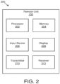
- Figure 2 depicts one embodiment of an apparatus 200 that may be used for determining a priority order based on uplink transmission parameters.
- the apparatus 200 includes one embodiment of the remote unit 102.
- the remote unit 102 may include a processor 202, a memory 204, an input device 206, a display 208, a transmitter 210, and a receiver 212.
- the input device 206 and the display 208 are combined into a single device, such as a touchscreen.
- the remote unit 102 may not include any input device 206 and/or display 208.
- the remote unit 102 may include one or more of the processor 202, the memory 204, the transmitter 210, and the receiver 212, and may not include the input device 206 and/or the display 208.
- the processor 202 may include any known controller capable of executing computer-readable instructions and/or capable of performing logical operations.
- the processor 202 may be a microcontroller, a microprocessor, a central processing unit (“CPU"), a graphics processing unit (“GPU”), an auxiliary processing unit, a field programmable gate array (“FPGA”), or similar programmable controller.
- the processor 202 executes instructions stored in the memory 204 to perform the methods and routines described herein.
- the processor 202 determines a priority order of multiple logical channels based on uplink transmission parameters and a logical channel priority of the multiple logical channels.
- the processor 202 assigns resources to logical channels of the multiple logical channels based on the priority order.
- the processor 202 is communicatively coupled to the memory 204, the input device 206, the display 208, the transmitter 210, and the receiver 212.
- the memory 204 in one embodiment, is a computer readable storage medium.
- the memory 204 includes volatile computer storage media.
- the memory 204 may include a RAM, including dynamic RAM (“DRAM”), synchronous dynamic RAM (“SDRAM”), and/or static RAM (“SRAM”).
- the memory 204 includes non-volatile computer storage media.
- the memory 204 may include a hard disk drive, a flash memory, or any other suitable non-volatile computer storage device.
- the memory 204 includes both volatile and non-volatile computer storage media.
- the memory 204 stores data relating to a priority order.
- the memory 204 also stores program code and related data, such as an operating system or other controller algorithms operating on the remote unit 102.
- the input device 206 may include any known computer input device including a touch panel, a button, a keyboard, a stylus, a microphone, or the like.
- the input device 206 may be integrated with the display 208, for example, as a touchscreen or similar touch-sensitive display.
- the input device 206 includes a touchscreen such that text may be input using a virtual keyboard displayed on the touchscreen and/or by handwriting on the touchscreen.
- the input device 206 includes two or more different devices, such as a keyboard and a touch panel.
- the display 208 may include any known electronically controllable display or display device.
- the display 208 may be designed to output visual, audible, and/or haptic signals.
- the display 208 includes an electronic display capable of outputting visual data to a user.
- the display 208 may include, but is not limited to, an LCD display, an LED display, an OLED display, a projector, or similar display device capable of outputting images, text, or the like to a user.
- the display 208 may include a wearable display such as a smart watch, smart glasses, a heads-up display, or the like.
- the display 208 may be a component of a smart phone, a personal digital assistant, a television, a table computer, a notebook (laptop) computer, a personal computer, a vehicle dashboard, or the like.
- the display 208 includes one or more speakers for producing sound.
- the display 208 may produce an audible alert or notification (e.g., a beep or chime).
- the display 208 includes one or more haptic devices for producing vibrations, motion, or other haptic feedback.
- all or portions of the display 208 may be integrated with the input device 206.
- the input device 206 and display 208 may form a touchscreen or similar touch-sensitive display.
- the display 208 may be located near the input device 206.
- the transmitter 210 is used to provide UL communication signals to the base unit 104 and the receiver 212 is used to receive DL communication signals from the base unit 104.
- the receiver 212 receives an uplink grant corresponding to uplink transmission parameters including an indication of a numerology and a transmission time interval length.
- the remote unit 102 may have any suitable number of transmitters 210 and receivers 212.
- the transmitter 210 and the receiver 212 may be any suitable type of transmitters and receivers.
- the transmitter 210 and the receiver 212 may be part of a transceiver.
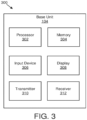
- Figure 3 depicts one embodiment of an apparatus 300 that may be used for transmitting uplink transmission parameters.
- the apparatus 300 includes one embodiment of the base unit 104.
- the base unit 104 may include a processor 302, a memory 304, an input device 306, a display 308, a transmitter 310, and a receiver 312.
- the processor 302, the memory 304, the input device 306, the display 308, the transmitter 310, and the receiver 312 may be substantially similar to the processor 202, the memory 204, the input device 206, the display 208, the transmitter 210, and the receiver 212 of the remote unit 102, respectively.
- the transmitter 310 is used to transmit an uplink grant corresponding to uplink transmission parameters including an indication of a numerology and a transmission time interval length.
- the base unit 104 may have any suitable number of transmitters 310 and receivers 312.
- the transmitter 310 and the receiver 312 may be any suitable type of transmitters and receivers.
- the transmitter 310 and the receiver 312 may be part of a transceiver.
- Figure 4 is a schematic flow chart diagram illustrating one embodiment of a method 400 for determining a priority order based on an uplink transmission parameter.
- the method 400 is performed by an apparatus, such as the remote unit 102.
- the method 400 may be performed by a processor executing program code, for example, a microcontroller, a microprocessor, a CPU, a GPU, an auxiliary processing unit, a FPGA, or the like.
- each numerology e.g., subcarrier spacing, OFDM symbol duration, CP duration, number of symbols per scheduling interval, etc.
- TTI that is configured for a logical channel as an allowed numerology and/or TTI may be associated with a priority.
- a UE and/or MAC may consider both the numerology priority as well as the logical channel priority in order to determine the order in which logical channels are served.
- a logical channel is configured to use multiple numerologies and/or TTI(s) for transmission, the configured allowed numerologies have a certain priority order which a UE may respect during the LCP procedure.
- a logical channel may include a preferred/primary numerology/TTI (e.g., uplink transmission parameter) and a secondary numerology/TTI (e.g., uplink transmission parameter).
- a preferred/primary numerology/TTI e.g., uplink transmission parameter
- a secondary numerology/TTI e.g., uplink transmission parameter
- the preferred/primary numerology/TTI may be the numerology best suited for transmission of data of a particular logical channel according to service/QoS requirements.
- the preferred/primary numerology/TTI may have the highest priority among the allowed numerologies.
- the priority of the secondary numerologies may be in the order of configuration (e.g., first configured secondary numerology has a second highest priority, second configured secondary numerology has a third highest priority, and so forth).
- the priority of the numerologies associated with a logical channel may be respected by the UE during an LCP procedure (e.g., logical channels that have an indicated numerology in an UL grant configured as the preferred/primary numerology may be prioritized over logical channels which have the indicated numerology only configured as a secondary numerology/TTI). Accordingly, data of logical channels may be transmitted with the best suited numerology scheme to facilitate complying with requirements of a numerology configuration.
- the method 400 includes receiving 402 an UL grant for a numerology/TTI X.
- the method 400 also includes determining 404 a set of logical channels having data available for transmission that have numerology/TTI X as a configured numerology/TTI.
- the method 400 further determines a priority order among the logical channels of above determined set of logical channels based on a numerology/TTI priority and a logical channel priority.
- the method 400 includes determining 406 logical channels of the set of logical channels that have numerology/TTI X as a preferred/primary numerology/TTI.
- the method 400 determines 408 whether there are multiple logical channels that have numerology/TTI X as the preferred/primary numerology/TTI.
- the method 400 assigns 410 the one logical channel having numerology/TTI X as the preferred/primary numerology/TTI as the highest priority.
- the method 400 orders 412 the multiple logical channels according to a configured logical channel priority (e.g., in decreasing priority order).
- the method 400 orders 414 logical channels having numerology/TTI X as a secondary numerology/TTI according to a secondary level and the logical channel priority.
- the method 400 orders 414 the logical channels having X as a secondary numerology/TTI by setting logical channels having the indicated numerology/TTI X as a first secondary numerology/TTI to a higher priority than logical channels having the indicated numerology/TTI X as a second secondary numerology/TTI, and so forth. Then, for logical channels having multiple first or second secondary numerologies that have the indicated numerology/TTI X, the channels are ordered in priority based on the logical channel priority.
- the method 400 assigns 416 resources to individual logical channels which are part of the set of logical channels considering the computed priority order of the logical channels using the LCP procedure.
- a UE has three logical channels LCH #1, LCH #2, and LCH #3 as illustrated in Table 1.
- LCH #1 has numerology 1 as its primary numerology and numerology 3 as its first secondary numerology.
- LCH #2 has numerology 2 as its primary numerology, numerology 1 as its first secondary numerology, and numerology 3 as its second secondary numerology.
- LCH #3 has numerology 3 as its primary numerology and numerology 1 as its first secondary numerology.
- LCH #2 has the highest priority with a logical channel priority of 1
- LCH #1 has the second highest priority with a logical channel priority of 2
- LCH #3 has the third highest priority (e.g., lowest priority) with a logical channel priority of 3.
- data of LCH #1 may be prioritized over data of LCH #2 and LCH #3 regardless of the configured logical channel priority because numerology 1 is only a primary numerology for LCH #1.
- the logical channel priority order is: LCH #1, LCH #2, LCH#3. This is because LCH #1 is the only logical channel with numerology 1 as the primary numerology, and while LCH #2 and LCH #3 both have numerology 1 as the first secondary numerology, LCH #2 has a higher priority (e.g., 1) than LCH #3 (e.g., 3).
- the logical channel priority order is: LCH #3, LCH #1, LCH #2. This is because LCH #3 is the only logical channel with numerology 3 as the primary numerology, LCH #1 is the only logical channel with numerology 3 as the first secondary numerology, and LCH #2 is the only logical channel with numerology 3 as the second secondary numerology.
- Figure 5 is a schematic flow chart diagram illustrating another embodiment of a method 500 for determining a priority order based on an uplink transmission parameter.
- the method 500 is performed by an apparatus, such as the remote unit 102.
- the method 500 may be performed by a processor executing program code, for example, a microcontroller, a microprocessor, a CPU, a GPU, an auxiliary processing unit, a FPGA, or the like.
- the network configures a preferred/primary numerology and a maximum TTI length for each logical channel.
- the primary/preferred numerology is the numerology best suited for transmission of data of the logical channel in order to meet the QoS requirement (e.g., latency and reliability).
- the maximum TTI length value allows a logical channel to use all the TTI lengths (regardless of the numerology) unless the TTI length cannot meet the delay requirement of the logical channel. Therefore, data of a logical channel may be transmitted using any numerology as long as the TTI length is equal to or smaller to the configured maximum TTI length.
- TTI length which is the schedulable unit of time from MAC point of view, depends not only on the used numerology (e.g., subcarrier spacing "SCS"), but also on the number of used OFDM symbols.
- a TTI length may be reduced by keeping the same numerology (or SCS), but reducing the number of OFDM symbols per TTI (e.g., using only two symbols per TTI), or by keeping the same number of OFDM symbols but scaling the SCS (e.g., reducing the symbol length).
- reducing the OFDM symbol length by SCS scaling may have certain benefits over reducing the number of OFDM symbols (e.g., for the same SCS). For example, the smaller symbol length by SCS scaling may become a useful tool to enable fast pipeline processing of both UL and DL channels (e.g., short TTI length by scaling SCS (i.e., scaling down the symbol duration) further tightens processing timeline and HARQ RTT).
- short TTI length by scaling SCS i.e., scaling down the symbol duration
- the MAC layer is aware of the numerology used for an uplink transmission and the TTI length. Based on the numerology and TTI length, as indicated by the physical layer ("PHY") to the MAC upon reception of an uplink grant, the logical channel to resource mapping (e.g., LCP procedure) is performed.
- the MAC entity prioritizes those logical channels for which the configured preferred/primarily numerology is the same as the indicated numerology for the uplink transmission. This prioritization ensures that the data of those logical channels is always transmitted with the best suited numerology configuration to facilitate complying with the requirements for which the numerology configuration was configured. If there are remaining resources available, logical channels for which the configured maximum TTI length is equal or larger than the indicated TTI length are considered for transmission.
- the method 500 includes receiving 502 an UL grant for a numerology X and a TTI length Y, i.e., uplink transmission according to received uplink grant uses numerology X and TTI length Y.
- the method 500 also includes determining 504 a set of logical channels that have numerology X as a preferred/primary numerology.
- the method 500 further determines a priority order among the logical channels of above determined set of logical channels based on a logical channel priority. Specifically, the method 500 determines 506 whether there are multiple logical channels that have numerology X as the preferred/primary numerology.
- the method 500 assigns 508 the one logical channel having numerology X as the preferred/primary numerology as the highest priority.
- the method 500 orders 510 the multiple logical channels according to a configured logical channel priority (e.g., in decreasing priority order).
- the method 500 orders 512 logical channels having a maximum TTI length greater than or equal to Y according to the logical channel priority (if there are resources remaining).
- the method 500 assigns 514 resources to individual logical channels based on the computed priority order of the logical channels using the LCP procedure.
- the LCP procedure is performed as defined in TS36.321 section 5.4.3.1 (e.g., using token bucket, using a two-step procedure, etc.).
- the method 500 first assigns resources to the logical channels that have numerology X as the preferred/primary numerology based on the computed priority order 508 respectively 510 using the LCP procedure and subsequently assigns remaining resources (if any) to logical channels having a maximum TTI length greater than or equal to Y based on the computed priority order 512.
- a UE has four logical channels LCH #1, LCH #2, LCH #3, and LCH #4 as illustrated in Table 2.
- LCH #1 has numerology 1 as its primary numerology and 1 ms as its maximum TTI.
- LCH #2 has numerology 2 as its primary numerology and 0.5 ms as its maximum TTI.
- LCH #3 has numerology 3 as its primary numerology and 1 ms as its maximum TTI.
- LCH #4 has numerology 1 as its primary numerology and 1 ms as its maximum TTI.
- LCH #2 has the highest priority with a logical channel priority of 1
- LCH #1 has the second highest priority with a logical channel priority of 2
- LCH #3 has the third highest priority with a logical channel priority of 3
- LCH #4 has the fourth highest priority (e.g., lowest priority) with a logical channel priority of 4.
- Table 2 LCH #1 (Priority 2)
- LCH #2 (Priority 1)
- LCH #3 (Priority 3)
- Primary Numerology 3
- the logical channel priority order is: LCH #1, LCH #4, LCH#3. This is because LCH #1 and LCH #4 both have numerology 1 as the primary numerology and LCH #1 is before LCH #4 because LCH #1 has a channel priority of 2 which is higher than the channel priority of 4 for LCH #4, and LCH #3 is the only remaining channel that has a maximum TTI length greater than or equal to 1 ms.
- the logical channel priority order is: LCH #2, LCH #1, LCH #3, LCH #4.
- LCH #2 is the only logical channel with numerology 2 as the primary numerology, and all of LCH #1, LCH #3, and LCH #4 have a maximum TTI length greater than or equal to 0.5 ms and LCH #1, LCH #3, and LCH #4 are then ordered based on their channel priority.
- the logical channel priority order is: LCH #1, LCH #4, LCH #2, LCH#3.
- LCH #1 and LCH #4 both have numerology 1 as the primary numerology and LCH #1 is before LCH #4 because LCH #1 has a channel priority of 2 which is higher than the channel priority of 4 for LCH #4, and both of LCH #2 and LCH #3 have a maximum TTI length greater than or equal to 0.5 ms and LCH #2 and LCH #3 are then ordered based on their channel priority.
- the logical channel priority order is: LCH #3, LCH #1, LCH #4.
- LCH #3 is the only logical channel with numerology 3 as the primary numerology, and both of LCH #1 and LCH #4 have a maximum TTI length greater than or equal to 1 ms and LCH #1 and LCH #4 are then ordered based on their channel priority.
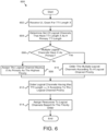
- Figure 6 is a schematic flow chart diagram illustrating a further embodiment of a method 600 for determining a priority order based on an uplink transmission parameter.
- the method 600 is performed by an apparatus, such as the remote unit 102.
- the method 600 may be performed by a processor executing program code, for example, a microcontroller, a microprocessor, a CPU, a GPU, an auxiliary processing unit, a FPGA, or the like.
- the network configures a preferred/primary TTI length and a maximum TTI length for each logical channel.
- the primary/preferred TTI length may be the TTI length best suited for transmission of data of a particular logical channel in order to meet the QoS requirement like latency.
- the maximum TTI length value allows a logical channel to use all the TTI lengths (regardless of the numerology) unless the TTI length cannot meet the delay requirement of the channel. Therefore, data of a logical channel may be transmitted using any TTI/numerology as long as the TTI length is equal or smaller than the configured maximum TTI length.
- the MAC needs to be aware only of the TTI length used for the uplink transmission when performing the logical channel to resource mapping (e.g., LCP procedure).
- the only restriction of limiting some logical channels to certain resources corresponds to the delay requirement, which may equate with TTI length from the MAC point of view, regardless of the TTI length results from different numerologies (e.g., SCS scaling), or different number of OFDM symbols of one numerology.
- numerology may be transparent to the MAC.
- the MAC prioritizes logical channels for which the configured preferred/primarily TTI is same as the indicated TTI length for the uplink transmission. If there are remaining resources available, logical channels for which the configured maximum TTI length is equal or larger than the indicated TTI length are considered for transmission.
- the method 600 includes receiving 602 an UL grant for a TTI length X.
- the method 600 also includes determining 604 a set of logical channels that have the TTI length X as indicated in the UL grant as a preferred/primary TTI length.
- the method 600 further determines a priority order among the logical channels of above determined set of logical channels based on a logical channel priority. Specifically, the method 600 determines 606 whether there are multiple logical channels that have TTI length X as the preferred/primary TTI length.
- the method 600 assigns 608 the one logical channel having TTI length X as the preferred/primary TTI length as the highest priority.
- the method 600 orders 610 the multiple logical channels according to a configured logical channel priority (e.g., in decreasing priority order).
- the method 600 orders 612 logical channels having a maximum TTI length greater than or equal to X according to the logical channel priority (if there are resources remaining).
- the method 600 assigns 614 resources to individual logical channels based on the computed priority order of the logical channels using the LCP procedure.
- the method 600 first assigns resources to the logical channels that have TTI length X as the preferred/primary TTI length based on the computed priority order 608 respectively 610 using the LCP procedure and subsequently assigns remaining resources (if any) to logical channels having a maximum TTI length greater than or equal to X based on the computed priority order 612.
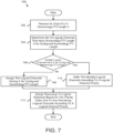
- Figure 7 is a schematic flow chart diagram illustrating yet another embodiment of a method 700 for determining a priority order based on an uplink transmission parameter.
- the method 700 is performed by an apparatus, such as the remote unit 102.
- the method 700 may be performed by a processor executing program code, for example, a microcontroller, a microprocessor, a CPU, a GPU, an auxiliary processing unit, a FPGA, or the like.
- each logical channel may be configured with a numerology/TTI. This configuration is the best suited numerology/TTI for transmission.
- the MAC entity prioritizes those logical channels having the configured numerology/TTI the same as the numerology/TTI used for the uplink transmission. For configurations in which there are multiple logical channels with a configured numerology/TTI the same as the indicated numerology/TTI, the logical channels are served in descending priority order (e.g., according to the logical channel priority). For the remaining resources (if any) all other logical channels are considered (e.g., in descending logical channel priority order).
- the method 700 includes receiving 702 an UL grant for a numerology/TTI length X.
- the method 700 also includes determining 704 a set of logical channels that have the numerology/TTI length X as the configured numerology/TTI length.
- the method 700 further determines a priority order among the logical channels of above determined set of logical channels based on a logical channel priority. Specifically, the method 700 determines 706 whether there are multiple logical channels that have the numerology/TTI length X as the configured numerology/TTI length.
- the method 700 assigns 708 the one logical channel having the numerology/TTI length X as the configured numerology/TTI length as the highest priority. In response to determining 706 that there are multiple logical channels having the numerology/TTI length X as the configured numerology/TTI length, the method 700 orders 710 the multiple logical channels according to a configured logical channel priority (e.g., in decreasing priority order).
- a configured logical channel priority e.g., in decreasing priority order.
- the method 700 assigns 712 resources to individual logical channels based on the computed priority order of the logical channels using the LCP procedure and to any remaining logical channels according to a configured logical channel priority (e.g., in decreasing priority order) if remaining resources are available.
- a configured logical channel priority e.g., in decreasing priority order
- Certain embodiments described herein relate to the prioritization/restriction of a data radio bearer ("DRB") respectively to a corresponding dedicated traffic channel (“DTCH”).
- DRB data radio bearer
- DTCH dedicated traffic channel
- the local channel to resource restrictions described herein may not be applied to specific logical channels (e.g., signaling radio bearers).
- a remote unit 102 may be enabled to transmit a measurement report on any numerology/TTI.
- the network e.g. gNB
- a specific codepoint may be defined within the RRC configuration (e.g., RRC configuration which configures the preferred/primary numerology/TTI) indicating that the logical channel considers any numerology/TTI as its preferred/primary numerology/TTI.
- RRC configuration e.g., RRC configuration which configures the preferred/primary numerology/TTI
- MAC control elements may be prioritized over data from logical channels.
- certain logical channels may be prioritized over MAC control elements.
- data of logical channels which tolerate a very low latency may be prioritized over MAC control elements.
- the data from some logical channels may be prioritized over MAC control elements.
- the data from logical channels may be prioritized over MAC control elements.
- the data from logical channels may be prioritized over MAC control elements.
- a numerology which is used for URLLC communication e.g., short symbol length
- the data from logical channels having the numerology/TTI length used for the uplink transmission (as indicated by PHY to MAC) configured as a preferred/primary numerology/TTI may be prioritized over MAC control elements and data from other logical channels may not be prioritized over MAC control elements.
- the dynamic resource scheduling mode is characterized in that the remote unit 102 will not autonomously perform uplink transmissions but will follow corresponding uplink scheduling assignments provided by the network (e.g., base unit 104, gNB). However, in some situations, uplink transmissions may be significantly delayed because the remote unit 102 has to first request and then receive a suitable uplink grant before performing the uplink transmissions.
- a grant-free scheduling mode may allow the remote unit 102 to immediately perform uplink transmissions in certain circumstances without having to request or receive a corresponding resource allocation from the network, thereby significantly reducing the delay.
- the grant-free scheduling mode may only be used for certain logical channels (e.g., URLLC).
- the network configures whether a logical channel is allowed to use the grant-free scheduling mode.
- the relative priority order as defined in TS36.321 section 5.4.3.1, which the MAC considers during logical channel prioritization, may be different depending on the scheduling mode. Specifically, data from logical channels which are using the grant-free scheduling mode may be prioritized over MAC control elements.
- the MAC may use a different relative priority compared to a configuration in which an uplink resource is allocated by an UL grant (e.g., dynamically).
- the network may benefit from receiving MAC control elements as quickly as possible (e.g., for uplink scheduling keeping the reporting delay for buffer status report ("BSR") and power headroom report (“PHR”) short may be important).
- BSR buffer status report
- PHR power headroom report
- the remote unit 102 is scheduled for transmission of multiple transport blocks at the same time (e.g., in carrier aggregation). Accordingly, in such embodiments, the remote unit 102 may map MAC control elements to the transport block using the smallest TTI length respectively HARQ RTT. This may ensure that MAC control elements are received with the shortest delay so that the base unit 104 may use of the information carried in the MAC control elements as quickly as possible.
- a mapping between a MAC control element and allowed numerologies/TTI(s) may be performed. This mapping may be configured by network signaling or hard-coded in a specification. Thus, the remote unit 102 may use this configuration during the LCP procedure (e.g., when generating a transport block). In various embodiments, the mapping configuration enables the network to inhibit a remote unit 102 from mapping certain MAC control elements to specific numerologies/TTI (e.g., MAC control elements may not be mapped to a numerology used for delay-critical services like URLLC). In one embodiment, a mapping between a MAC control element and scheduling modes may be performed. This mapping may be configured by network signaling or hard-coded in a specification.
- the remote unit 102 may use this configuration during the LCP procedure (e.g., when generating a transport block).
- the mapping configuration enables the network to inhibit a remote unit 102 from mapping certain MAC control elements uplink transmissions using a certain scheduling mode (e.g., MAC control elements may not be mapped to a transport block using the grant-free scheduling mode like for URLLC transmission using the grant-free scheduling mode).
- MAC control elements may be configured so that numerology/TTI restrictions are not applied.
- the network may configure a MAC control element to be mapped to any numerology/TTI length.
- a specific codepoint may be defined within the RRC configuration (e.g., RRC configuration which configures the preferred/primary numerology/TTI) indicating that the logical channel identity identifying the MAC control element considers any numerology/TTI as its preferred/primary numerology/TTI.
- a specification or elsewhere may indicate that MAC control elements may be transmitted using any numerology/TTI.
- an RRC inactive state indicates a power optimized state in which a remote unit 102 is allowed to transmit a certain amount of data (e.g., small data) without needing to transition to an RRC connected state.
- a certain amount of data e.g., small data
- in the RRC inactive state there may be no logical channel to numerology/TTI restriction when the remote unit 102 performs LCP/UL data transmission.
- each logical channel may use all the TTI lengths of any numerology.
- the network when a remote unit 102 is directed into the inactive state by the network and (later on) intends to transmit on uplink, the network may have no knowledge about the remote unit's radio conditions and also may not be aware of the buffer status of the remote unit 102 (e.g., network doesn't know which data the remote unit 102 intends to transmit).
- the base unit 104 may not be able to assign resources for a certain numerology/TTI which are suitable for the data the remote unit 102 intends to transmit.
- the remote unit 102 may transmit uplink data in a contention based manner (e.g., without prior reception of an uplink grant) and there may not be much benefit in restricting the LCH to numerology/TTI mapping.
- the MAC in the remote unit 102 upon being directed to an inactive mode, the MAC in the remote unit 102 may disable all previously configured restrictions (e.g., logical channel to numerology/TTI mapping).
- a PBR value may depend on whether a numerology/TTI length used for an uplink transmission is considered/not considered as the primary/preferred numerology/TTI of a logical channel.
- the data transmission of this logical channel may be maximized (e.g., the MAC may allocate resources for all the data from that logical channel before meeting the PBR of the logical channel(s) for which the numerology is not the preferred/primary numerology/TTI).
- the priority order of the logical channels for an UL grant using numerology 1 may be: LCH#1, LCH#2, LCH#3.
- the MAC may allocate all the data that is available for transmission from LCH #1, before allocating any (remaining) resources to LCH#2, LCH#3.
- the behavior according to this aspect may be implemented by defining that the PBR of LCH #1 is indicated as infinity (e.g., the MAC may allocate resources for all the data that is available for transmission on that logical channel before meeting the PBR of the lower priority logical channel(s)).
- this behavior may be implemented when performing the LCP procedure first for all the logical channels having the indicated numerology (in UL grant) as primary/preferred numerology and then subsequently performing the LCP procedure for all the logical channels having the indicated numerology as a secondary numerology.
- Figure 8 is a schematic flow chart diagram illustrating a further embodiment of a method 800 for determining a priority order based on an uplink transmission parameter.
- the method 800 is performed by an apparatus, such as the remote unit 102.
- the method 800 may be performed by a processor executing program code, for example, a microcontroller, a microprocessor, a CPU, a GPU, an auxiliary processing unit, a FPGA, or the like.
- the method 800 may include receiving 802 an uplink grant corresponding to an uplink transmission parameter (e.g., numerology, TTI length, etc.).
- the method 800 also includes determining 804 a priority order of multiple logical channels based on an uplink transmission parameter priority corresponding to the uplink transmission parameter and a logical channel priority of the multiple logical channels.
- the method 800 includes assigning 806 resources to logical channels of the plurality of logical channels based on the priority order.
- the uplink transmission parameter includes an indication of a numerology.
- the numerology includes a subcarrier spacing, an orthogonal frequency-division multiplexing symbol duration, a cyclic prefix duration, a number of symbols per scheduling interval, or some combination thereof.
- the uplink transmission parameter includes an indication of a transmission time interval.
- each logical channel of the multiple logical channels includes a primary uplink transmission parameter and one or more secondary uplink transmission parameters.
- a primary uplink transmission parameter has a first priority
- each of one or more secondary uplink transmission parameters has a respective priority from a set of one or more second priorities
- the first priority is greater than each priority of the set of one or more second priorities
- each priority of the set of one or more priorities is ranked relative to the other priorities of the set of one or more priorities.
- the primary uplink transmission parameter and the one or more secondary uplink transmission parameter each include a numerology, a transmission time interval length, or some combination thereof.
- the processor determines the priority order of the multiple logical channels based on the uplink transmission parameter priority corresponding to the uplink transmission parameter and the logical channel priority of the multiple logical channels by: selecting a first set of logical channels of the multiple logical channels in response to the primary uplink transmission parameter of logical channels of the first set of logical channels matching the uplink transmission parameter and ordering the logical channels of the first set of logical channels according to a logical channel priority of each logical channel of the first set of logical channels; and for each secondary uplink transmission parameter of the one or more secondary uplink transmission parameters, selecting a second set of logical channels of the multiple logical channels in response to the respective secondary uplink transmission parameter of logical channels of the second set of logical channels matching the uplink transmission parameter and ordering the logical channels of the second set of logical channels according to a logical channel priority of each logical channel
- ordering the logical channels of the first set of logical channels includes ordering the logical channels of the first set of logical channels in descending priority order
- ordering the logical channels of the second set of logical channels includes ordering the logical channels of the second set of logical channels in descending priority order.
- the uplink transmission parameter priority includes a first priority corresponding to a first uplink transmission parameter and a second priority corresponding to a second uplink transmission parameter.
- the first uplink transmission parameter includes a primary numerology and the second uplink transmission parameter includes a maximum transmission time interval length.
- the first uplink transmission parameter includes a primary transmission time interval length and the second uplink transmission parameter comprises a maximum transmission time interval length.
- the uplink transmission parameter priority is disregarded during operation in an inactive mode.
- the processor determines the priority order of the multiple logical channels based on the uplink transmission parameter priority corresponding to the uplink transmission parameter and the logical channel priority of the multiple logical channels by: selecting a first set of logical channels of the multiple logical channels in response to a primary uplink transmission parameter of logical channels of the first set of logical channels matching the uplink transmission parameter and ordering the logical channels of the first set of logical channels according to a logical channel priority of each logical channel of the first set of logical channels; and selecting a second set of logical channels of the multiple logical channels in response to a secondary uplink transmission parameter of logical channels of the second set of logical channels matching the uplink transmission parameter and ordering the logical channels of the second set of logical channels according to a logical channel priority of each logical channel
- logical channels of the first set of logical channels are prioritized over a medium access control control element.
- ordering the logical channels of the first set of logical channels includes ordering the logical channels of the first set of logical channels in descending priority order
- ordering the logical channels of the second set of logical channels includes ordering the logical channels of the second set of logical channels in descending priority order.
- each logical channel of the multiple logical channels includes a primary uplink transmission parameter.
- the primary uplink transmission parameter includes a numerology, a transmission time interval length, or some combination thereof.
- the processor determines the priority order of the multiple logical channels based on the uplink transmission parameter priority corresponding to the uplink transmission parameter and the logical channel priority of the multiple logical channels by: selecting a first set of logical channels of the multiple logical channels in response to a primary uplink transmission parameter of logical channels of the first set of logical channels matching the uplink transmission parameter and ordering the logical channels of the first set of logical channels according to a logical channel priority of each logical channel of the first set of logical channels; and selecting a second set of logical channels of the multiple logical channels in response to a primary uplink transmission parameter of logical channels of the second set of logical channels not matching the uplink transmission parameter and ordering the logical channels of the second set of logical channels according to a logical channel priority of each logical channel of the second set of logical channels.
- ordering the logical channels of the first set of logical channels includes ordering the logical channels of the first set of logical channels in descending priority order
- ordering the logical channels of the second set of logical channels includes ordering the logical channels of the second set of logical channels in descending priority order.
- a logical channel of the multiple logical channels includes a primary uplink transmission parameter that indicates that the logical channel considers any numerology or any transmission time interval length as the primary uplink transmission parameter.
- a logical channel of the multiple logical channels includes a primary uplink transmission parameter that is prioritized over medium access control control elements.
- the processor associates the uplink transmission parameter with a medium access control control element.
- a medium access control control element includes a primary uplink transmission parameter that indicates that a medium access control control element considers any numerology or any transmission time interval length as the primary uplink transmission parameter.
- the processor determines a prioritized bit rate based on the uplink transmission parameter priority.
- a priority order may be determined based on multiple uplink transmission parameters.
- a base unit 104 may configure a preferred/primary numerology or a set of allowed numerologies and a maximum TTI length for each logical channel.
- the primary/preferred numerology is a numerology best suited for transmission of data of the logical channel in order to meet a QoS requirement (e.g., reliability).
- "allowed" numerologies may refer to numerologies which are suited for transmission of data of the logical channel in order to meet the QoS requirement (e.g., reliability).
- a maximum TTI length value enables a logical channel to use all TTI lengths unless the TTI length cannot meet a delay requirement of the logical channel.
- data of a logical channel may be transmitted as long as the TTI length is equal to or smaller a configured maximum TTI length.
- TTI length which may refer to a schedulable unit of time from a MAC point of view, may depend not only on a used numerology (e.g., subcarrier spacing "SCS"), but also on a number of used OFDM symbols.
- a MAC layer is aware of a numerology used for an uplink transmission and the TTI length.
- a logical channel to resource mapping (e.g., LCP procedure) may be performed.
- a MAC entity in response to an uplink grant being received, considers only those logical channels that have a configured (e.g., allowed) numerology and maximum TTI that matches with the UL grant during logical channel to resource mapping (e.g., during the LCP procedure). In such embodiments, this may facilitate reliability as well as latency requirements of the logical channels to be met.
- an order in which the considered LCHs are served is based on a configured logical channel priority.
- a base unit 104 may configure a set of allowed numerologies and a maximum TTI length for each configured "allowed" numerology for a logical channel.
- the "allowed" numerologies may define the numerologies which are suited for transmission of data of the logical channel in order to meet a QoS requirement (e.g., reliability).
- a maximum TTI length value enables a logical channel to use all the TTI lengths unless the TTI length cannot meet the delay requirement of the logical channel.
- data of a logical channel may be transmitted as long as a TTI length is equal to or smaller than a configured maximum TTI length.
- a maximum TTI length may depend on a used numerology.
- a MAC layer may be aware of a numerology used for an uplink transmission and a TTI length. Based on the numerology and TTI length, as indicated by the PHY to the MAC upon reception of an uplink grant, a logical channel to resource mapping (e.g., LCP procedure) may be performed.
- LCP procedure a logical channel to resource mapping
- a MAC entity in response to an uplink grant being received, may consider only logical channels that have a configured (e.g., allowed) numerology and a corresponding maximum TTI length that matches with the UL grant during logical channel to resource mapping (e.g., during the LCP procedure). This may facilitate reliability as well as latency requirements of a logical channels to be met.
- an order in which considered LCHs are served may be based on a configured logical channel priority.
- a same TTI may result from different numerologies.
- a TB in response to having numerology specific power control settings/parameters (e.g., P 0 , alpha), a TB may contain data of a LCH using a numerology which is not suited for transmission, if only TTI length is considered during LCP (e.g., logical channel restriction).
- a MAC may multiplex URLLC data on the TB (since TTI length is matching) even though the numerology may not be suited for URLLC (e.g., reliability requirement for URLLC may not be met). Therefore, in some embodiments, numerology and TTI length may be considered for LCP procedure.
- a used numerology for an uplink transmission may be indicated to a MAC layer by an index (e.g., PHY doesn't indicate a full set of parameters associated with a numerology like SCS, CP length).
- the index may refer to a list describing used numerologies and their parameters (e.g., subcarrier spacing, CP length, etc.).
- numerologies in a list may be ordered according to reliability requirements (e.g., block error ratio "BLER"). For example, a numerology referenced by index 1 may fulfill the most stringent reliability requirements (e.g., lowest BLER).
- a base unit 104 may configure a maximum numerology and a maximum TTI length for each logical channel.
- a MAC layer may be aware of the numerology (e.g.., index) used for an uplink transmission and the TTI length. Based on the numerology and TTI length, as indicated by the PHY to the MAC upon reception of an uplink grant, a logical channel to resource mapping (e.g., LCP procedure) may be performed.
- a MAC in response to an uplink grant being received, a MAC may consider only those logical channels that have a configured maximum numerology and maximum TTI that matches with the UL grant during logical channel to resource mapping (e.g., during the LCP procedure).
- only those logical channels are "allowed" for LCP for which the configured maximum numerology value is higher than or equal to the numerology index value indicated to MAC and for which the configured maximum TTI length is higher than or equal to the TTI length indicated to MAC. In such embodiments, this may facilitate that reliability as well as latency requirements of the logical channels are met.
- an order in which considered LCHs are served is based on a configured logical channel priority.
- each LCH may be configured with a set of "allowed" numerologies and optionally also with a maximum TTI length.
- multiple SR resources may be configured independently (e.g., SR resources may be configured per numerology).
- having multiple independent SR resources may be used to convey additional information within a scheduling request. For example, based on the SR resource used by a remote unit 102, a base unit 104 may determine a numerology requested by a remote unit 102 for a corresponding UL transmission. In some embodiments, for cases in which an LCH is configured with more than one numerology, a remote unit 102 may select a SR resource corresponding to a first configured numerology (e.g., highest priority numerology).
- the remote unit 102 may select an SR resource according to a first numerology configured for this LCH (e.g., a highest priority numerology). In some embodiments, a remote unit 102 may select a nearest SR resource from a set SR resources corresponding to configured resources.
- the order in which grants are processed may be left up to a remote unit 102 implementation.
- a remote unit 102 behavior may be predefined (e.g., an order in which TBs are generated).
- the content of corresponding TBs may be different.
- LCH#1 (Priority 1)
- LCH#2 (Priority 2)
- a remote unit 102 may receive two UL grants simultaneoulsy.
- the content of the TB may be: the remote unit 102 processes the second UL grant followed by the first UL grant.
- a first TB may use numerology 2 of LCH#1 (e.g., the size of the first TB fits the amount of data for LCH#1) and a second TB may use numerology 1 of LCH#2 (e.g., the size of the seoncd TB fits the amount of data for LCH#2).
- the content of the TB may be: the remote unit 102 processes the first UL grant followed by the second UL grant.
- a first TB may use numerology 1 of LCH#1 and LCH#2 (e.g., the size of the first TB does not fit the amount of data for LCH#1) and a second TB may use numerology 2 of LCH#1 plus padding (e.g., the size of the second TB is too large for the amount of data for LCH#1).
- the processing order may result in poor efficiency (e.g., padding is transmitted for TB2). Therefore, due to the logical channel restriction, processing order may make a difference.
- a base unit 104 may know a remote unit 102 behavior and the content of the TBs (e.g., the base unit 104 may update its buffer status information based on a predicated remote unit 102 behavior).
- a rule may be defined which specifies the remote unit 102 behavior (e.g., an order in which a remote unit 102 processes UL grants).
- a remote unit 102 may process first UL grants which consider a least number of logical channels (e.g., first process UL grant for numerology 2 in the example above).
- a remote unit 102 may determine an order according to some predefined numerology priority order.
- a component carrier order may be predefined or signalled to a remote unit 102.
- Figure 9 is a schematic flow chart diagram illustrating one embodiment of a method 900 for determining a priority order based on uplink transmission parameters.
- the method 900 is performed by an apparatus, such as the remote unit 102.
- the method 900 may be performed by a processor executing program code, for example, a microcontroller, a microprocessor, a CPU, a GPU, an auxiliary processing unit, a FPGA, or the like.
- the method 900 may include receiving 902 an uplink grant corresponding uplink transmission parameters including an indication of a numerology and a transmission time interval length.
- the method 900 also includes determining 904 a priority order of multiple logical channels based on the uplink transmission parameters and a logical channel priority of the multiple logical channels.
- the method 900 includes assigning 906 resources to logical channels of the multiple logical channels based on the priority order.
- the numerology includes a subcarrier spacing, an orthogonal frequency-division multiplexing symbol duration, a cyclic prefix duration, or some combination thereof.
- the method 900 includes determining the priority order of the multiple logical channels based on the uplink transmission parameters and the logical channel priority of the multiple logical channels by: selecting a set of logical channels of the multiple logical channels in response to a numerology parameter of each logical channel of the set of logical channels including the numerology and a maximum transmission time interval length of each logical channel of the set of logical channels being less than or equal to the transmission time interval length; and ordering the logical channels of the set of logical channels according to a logical channel priority of each logical channel of the set of logical channels.
- ordering the logical channels of the set of logical channels includes ordering the logical channels of the set of logical channels in descending priority order.
- the numerology parameter includes one or more numerologies.
- logical channels of the set of logical channels are prioritized over a medium access control control element.
- the indication of the numerology includes an index corresponding to the numerology.
- each logical channel of the multiple logical channels is configured with a set of numerologies allowed by the respective logical channel and a maximum transmission time interval length.
- each logical channel of the multiple logical channels is configured with a maximum numerology allowed by the respective logical channel and a maximum transmission time interval length.
- the method 900 includes determining the priority order of the multiple logical channels based on the uplink transmission parameters and the logical channel priority of the multiple logical channels by: selecting a set of logical channels of the multiple logical channels in response to a maximum numerology of each logical channel of the set of logical channels being less or equal to the numerology and a maximum transmission time interval length of each logical channel of the set of logical channels being less than or equal to the transmission time interval length; and ordering the logical channels of the set of logical channels according to a logical channel priority of each logical channel of the set of logical channels.
- the method 900 includes selecting a scheduling request resource for transmission, and the scheduling request resource corresponds to a numerology being requested for uplink transmission.
- the method 900 includes selecting the scheduling request resource according to a first numerology of a set of configured numerologies of a logical channel of the multiple logical channels for which a buffer status report is triggered due to data becoming available for transmission.
- the method 900 includes receiving multiple uplink grants and determining an order for processing the multiple uplink grants based on a number of logical channels of the multiple logical channels configured with a numerology corresponding to a respective uplink grant of the multiple uplink grants.
- the method 900 includes receiving multiple uplink grants and determining an order for processing the multiple uplink grants based on a predefined numerology priority order.
- the method 900 includes receiving multiple uplink grants and determining an order for processing the multiple uplink grants based on a predefined order, a signaled order, or some combination thereof.
Landscapes
- Engineering & Computer Science (AREA)
- Signal Processing (AREA)
- Computer Networks & Wireless Communication (AREA)
- Physics & Mathematics (AREA)
- Mathematical Physics (AREA)
- Mobile Radio Communication Systems (AREA)
- Time-Division Multiplex Systems (AREA)
Priority Applications (1)
| Application Number | Priority Date | Filing Date | Title |
|---|---|---|---|
| EP25194212.4A EP4622161A3 (fr) | 2018-04-25 | Détermination d'un ordre de priorité sur la base de paramètres de transmission en liaison montante |
Applications Claiming Priority (3)
| Application Number | Priority Date | Filing Date | Title |
|---|---|---|---|
| US15/496,960 US10334598B2 (en) | 2017-04-25 | 2017-04-25 | Determining a priority order based on uplink transmission parameters |
| PCT/US2018/029297 WO2018200632A1 (fr) | 2017-04-25 | 2018-04-25 | Détermination d'un ordre de priorité sur la base de paramètres de transmission de liaison montante |
| EP18723341.6A EP3616351B1 (fr) | 2017-04-25 | 2018-04-25 | Détermination d'un ordre de priorité sur la base de paramètres de transmission de liaison montante |
Related Parent Applications (2)
| Application Number | Title | Priority Date | Filing Date |
|---|---|---|---|
| EP18723341.6A Division EP3616351B1 (fr) | 2017-04-25 | 2018-04-25 | Détermination d'un ordre de priorité sur la base de paramètres de transmission de liaison montante |
| EP18723341.6A Division-Into EP3616351B1 (fr) | 2017-04-25 | 2018-04-25 | Détermination d'un ordre de priorité sur la base de paramètres de transmission de liaison montante |
Related Child Applications (2)
| Application Number | Title | Priority Date | Filing Date |
|---|---|---|---|
| EP25194212.4A Division EP4622161A3 (fr) | 2018-04-25 | Détermination d'un ordre de priorité sur la base de paramètres de transmission en liaison montante | |
| EP25194212.4A Division-Into EP4622161A3 (fr) | 2018-04-25 | Détermination d'un ordre de priorité sur la base de paramètres de transmission en liaison montante |
Publications (4)
| Publication Number | Publication Date |
|---|---|
| EP4404497A2 true EP4404497A2 (fr) | 2024-07-24 |
| EP4404497A3 EP4404497A3 (fr) | 2024-11-06 |
| EP4404497C0 EP4404497C0 (fr) | 2025-10-15 |
| EP4404497B1 EP4404497B1 (fr) | 2025-10-15 |
Family
ID=62117183
Family Applications (2)
| Application Number | Title | Priority Date | Filing Date |
|---|---|---|---|
| EP24181332.8A Active EP4404497B1 (fr) | 2017-04-25 | 2018-04-25 | Détermination d'un ordre de priorité sur la base de paramètres de transmission en liaison montante |
| EP18723341.6A Active EP3616351B1 (fr) | 2017-04-25 | 2018-04-25 | Détermination d'un ordre de priorité sur la base de paramètres de transmission de liaison montante |
Family Applications After (1)
| Application Number | Title | Priority Date | Filing Date |
|---|---|---|---|
| EP18723341.6A Active EP3616351B1 (fr) | 2017-04-25 | 2018-04-25 | Détermination d'un ordre de priorité sur la base de paramètres de transmission de liaison montante |
Country Status (6)
| Country | Link |
|---|---|
| US (4) | US10334598B2 (fr) |
| EP (2) | EP4404497B1 (fr) |
| KR (2) | KR102831493B1 (fr) |
| CN (2) | CN115348681B (fr) |
| BR (1) | BR112019022480A2 (fr) |
| WO (1) | WO2018200632A1 (fr) |
Families Citing this family (44)
| Publication number | Priority date | Publication date | Assignee | Title |
|---|---|---|---|---|
| EP3244677B1 (fr) * | 2016-05-13 | 2020-04-29 | Panasonic Intellectual Property Corporation of America | Mécanisme amélioré de mise en oeuvre de qualité de service de communication de véhicule |
| JP7144326B2 (ja) * | 2017-01-06 | 2022-09-29 | パナソニック インテレクチュアル プロパティ コーポレーション オブ アメリカ | 通信装置、送信方法および集積回路 |
| US10678637B2 (en) * | 2017-01-10 | 2020-06-09 | Qualcomm Incorporated | Techniques to improve data transfer reliability |
| WO2018129699A1 (fr) * | 2017-01-13 | 2018-07-19 | Qualcomm Incorporated | Priorisation de canaux logiques et mise en correspondance de canaux logiques avec différentes numérologies |
| CN108633088B (zh) * | 2017-03-24 | 2020-12-15 | 华为技术有限公司 | 资源调度的方法和装置 |
| US10334598B2 (en) * | 2017-04-25 | 2019-06-25 | Motorola Mobility Llc | Determining a priority order based on uplink transmission parameters |
| EP3641434B1 (fr) * | 2017-04-28 | 2022-06-01 | Beijing Xiaomi Mobile Software Co., Ltd. | Procédé, dispositif, équipement utilisateur et station de base pour configuration de porteuse de canal |
| US11528687B2 (en) * | 2017-05-03 | 2022-12-13 | Lg Electronics Inc. | Apparatus and method for transmitting a buffer status report |
| KR102349604B1 (ko) * | 2017-05-04 | 2022-01-11 | 삼성전자 주식회사 | 이동통신시스템에서 Logical Channel의 우선 순위에 따른 Uplink Scheduling 방법 |
| CN110603872B (zh) * | 2017-05-05 | 2022-08-16 | 中兴通讯股份有限公司 | 用于配置调度请求的方法和装置 |
| US20180324833A1 (en) * | 2017-05-05 | 2018-11-08 | Qualcomm Incorporated | Enhancements to logic channel prioritization procedure with multiple numerologies |
| WO2018232259A1 (fr) | 2017-06-15 | 2018-12-20 | Convida Wireless, Llc | Demandes de planification, rapports d'état et hiérarchisation de canal logique |
| KR102488339B1 (ko) | 2017-07-10 | 2023-01-13 | 삼성전자 주식회사 | 다중 스케쥴링 요청을 설정하는 방법 및 장치 |
| WO2019017739A1 (fr) * | 2017-07-21 | 2019-01-24 | Samsung Electronics Co., Ltd. | Procédé et appareil de transmission de données dans un système de communication |
| EP3656169A4 (fr) * | 2017-07-21 | 2021-04-07 | LG Electronics Inc. | Procédé d'exécution d'une procédure lcp dans un système de communications sans fil, et dispositif associé |
| WO2019033071A1 (fr) | 2017-08-10 | 2019-02-14 | Babaei Alireza | Multiplexage d'informations de commande de liaison montante |
| US20190052414A1 (en) * | 2017-08-10 | 2019-02-14 | Alireza Babaei | Multiplexing mechanism for uplink control information |
| US11343714B2 (en) * | 2017-09-12 | 2022-05-24 | Telefonaktiebolaget Lm Ericsson (Publ) | Radio communication of critical packet data units |
| CN111164906B (zh) | 2017-10-02 | 2022-10-18 | 联想(新加坡)私人有限公司 | 上行链路功率控制 |
| KR20250018562A (ko) * | 2017-11-14 | 2025-02-06 | 인터디지탈 패튼 홀딩스, 인크 | 무선 시스템에서의 보충 업링크 전송 |
| US10887788B2 (en) * | 2017-11-16 | 2021-01-05 | Htc Corporation | Device and method of handling scheduling requests for logical channels |
| TR201721796A2 (tr) * | 2017-12-26 | 2018-05-21 | T C Istanbul Medipol Ueniversitesi | Beşinci Nesil Hücresel Haberleşme Sistemlerinde Numeroloji Sayısının Optimizasyonu Ve Numeroloji Seçim Yöntemi |
| US10862613B2 (en) * | 2018-02-01 | 2020-12-08 | T-Mobile Usa, Inc. | Dynamic numerology based on services |
| US11490363B2 (en) | 2018-04-18 | 2022-11-01 | Google Llc | User device-initiated bandwidth request |
| US10609681B2 (en) * | 2018-04-24 | 2020-03-31 | Google Llc | User device-initiated request for resource configuration |
| WO2019216817A1 (fr) * | 2018-05-09 | 2019-11-14 | Telefonaktiebolaget Lm Ericsson (Publ) | Indicateur de canal logique |
| CN112313994B (zh) * | 2018-06-20 | 2024-02-27 | 富士通株式会社 | 发送装置、缓冲器控制方法、基站及无线通信系统 |
| US11317461B2 (en) * | 2018-08-08 | 2022-04-26 | FG Innovation Company Limited | Method and apparatus for generating MAC PDU |
| EP3611855B1 (fr) * | 2018-08-16 | 2020-10-07 | Shenzhen Goodix Technology Co., Ltd. | Détection de faux positifs dans un canal de commande de liaison descendante nb-iot basée sur un débit de code programmé et efficace |
| WO2020063408A1 (fr) * | 2018-09-28 | 2020-04-02 | Huawei Technologies Co., Ltd. | Attribution de ressources pour transmission avec autorisation configurée dans un spectre sans licence |
| KR102752920B1 (ko) | 2019-01-04 | 2025-01-10 | 삼성전자 주식회사 | 차세대 이동통신 시스템에서 저지연을 위한 상향링크 상태 보고를 수행하는 방법 및 장치 |
| WO2020145863A1 (fr) * | 2019-01-11 | 2020-07-16 | Telefonaktiebolaget Lm Ericsson (Publ) | Procédé et dispositif terminal pour transmission de données de liaison montante de canal logique |
| WO2020191720A1 (fr) * | 2019-03-28 | 2020-10-01 | Nokia Shanghai Bell Co., Ltd. | Priorisation de canal logique |
| CN111436068B (zh) * | 2019-03-28 | 2023-04-07 | 维沃移动通信有限公司 | 一种传输方法及终端 |
| CN111756506A (zh) * | 2019-03-29 | 2020-10-09 | 华为技术有限公司 | 传输上行信息的方法和通信装置 |
| EP4005254A1 (fr) * | 2019-07-23 | 2022-06-01 | Lenovo (Singapore) Pte. Ltd. | Plage de communication minimale pour tb de mac |
| WO2021031005A1 (fr) * | 2019-08-16 | 2021-02-25 | Nokia Shanghai Bell Co., Ltd. | Activation d'autorisation configurée par un équipement utilisateur |
| CN112584500A (zh) * | 2019-09-29 | 2021-03-30 | 夏普株式会社 | 由用户设备执行的方法以及用户设备 |
| KR102846901B1 (ko) | 2019-11-07 | 2025-08-14 | 지티이 코포레이션 | 무선 네트워크에서의 자원 할당 |
| WO2021159534A1 (fr) * | 2020-02-14 | 2021-08-19 | Oppo广东移动通信有限公司 | Procédé de détermination de ressources de transmission et appareils associés |
| CN115428382B (zh) * | 2020-04-14 | 2025-08-05 | 伟光有限公司 | 用于5g mac上行链路多载波授权调度的方法 |
| CN115669129A (zh) * | 2020-08-28 | 2023-01-31 | Oppo广东移动通信有限公司 | 数据传输方法、网络设备和终端设备 |
| WO2024063785A1 (fr) * | 2022-09-23 | 2024-03-28 | Zeku, Inc. | Appareil et procédé de traitement de priorisation de canal logique (lcp) de petits paquets à haute densité et haute priorité |
| CN119450778A (zh) * | 2023-07-28 | 2025-02-14 | 大唐移动通信设备有限公司 | 逻辑信道优先级确定方法及装置 |
Family Cites Families (17)
| Publication number | Priority date | Publication date | Assignee | Title |
|---|---|---|---|---|
| US20040228313A1 (en) * | 2003-05-16 | 2004-11-18 | Fang-Chen Cheng | Method of mapping data for uplink transmission in communication systems |
| DE602004012862T2 (de) * | 2004-10-01 | 2009-04-09 | Matsushita Electric Industrial Co., Ltd., Kadoma-shi | Dienstgüte-bewusste Ablaufsteuerung für Aufwärtsübertragungen über zugeordneten Kanälen |
| ATE518391T1 (de) * | 2006-12-21 | 2011-08-15 | Nxp Bv | Dienstgüte für wlan- und bluetooth-kombinationen |
| RU2476026C2 (ru) * | 2008-02-01 | 2013-02-20 | Интердиджитал Пэйтент Холдингз, Инк. | Способ и устройство для назначения приоритетов логическим каналам |
| US9167594B2 (en) * | 2008-09-22 | 2015-10-20 | Htc Corporation | Method and related device of a trigger mechanism of buffer status report and scheduling request in a wireless communication system |
| EP2244515A1 (fr) * | 2009-04-23 | 2010-10-27 | Panasonic Corporation | Procédure de priorisation de canal logique pour générer plusieurs blocs de transport de liaison montante |
| KR101335869B1 (ko) * | 2009-08-12 | 2013-12-02 | 엘지전자 주식회사 | 무선 통신 시스템에서 논리채널에 대한 자원 할당 방법 및 장치 |
| US9420511B2 (en) * | 2012-11-01 | 2016-08-16 | Intel Corporation | Signaling QoS requirements and UE power preference in LTE-A networks |
| CN105230103B (zh) * | 2013-05-17 | 2019-07-12 | 寰发股份有限公司 | 上报bsr的方法以及用户设备 |
| US10225065B2 (en) * | 2015-12-18 | 2019-03-05 | Qualcomm Incorporated | Common control channel subband design and signaling |
| US10200170B2 (en) * | 2016-03-09 | 2019-02-05 | Samsung Electronics Co., Ltd. | Method and apparatus for a multi-cell full-dimension MIMO system |
| US10349403B2 (en) * | 2016-08-25 | 2019-07-09 | Qualcomm Incorporated | Supporting different numerology configurations |
| US10225867B2 (en) * | 2016-09-02 | 2019-03-05 | Qualcomm Incorporated | Transmission configuration and format for random access messages |
| WO2018119749A1 (fr) * | 2016-12-28 | 2018-07-05 | Mediatek Singapore Pte. Ltd. | Procédés permettant de prendre en charge une transmission ul sur de multiples numérologies dans un système nr |
| WO2018128431A1 (fr) * | 2017-01-06 | 2018-07-12 | Lg Electronics Inc. | Procédé et équipement utilisateur pour transmettre une unité de données |
| WO2018129699A1 (fr) * | 2017-01-13 | 2018-07-19 | Qualcomm Incorporated | Priorisation de canaux logiques et mise en correspondance de canaux logiques avec différentes numérologies |
| US10334598B2 (en) | 2017-04-25 | 2019-06-25 | Motorola Mobility Llc | Determining a priority order based on uplink transmission parameters |
-
2017
- 2017-04-25 US US15/496,960 patent/US10334598B2/en active Active
-
2018
- 2018-04-25 CN CN202211003495.4A patent/CN115348681B/zh active Active
- 2018-04-25 EP EP24181332.8A patent/EP4404497B1/fr active Active
- 2018-04-25 KR KR1020247043095A patent/KR102831493B1/ko active Active
- 2018-04-25 WO PCT/US2018/029297 patent/WO2018200632A1/fr not_active Ceased
- 2018-04-25 BR BR112019022480-7A patent/BR112019022480A2/pt unknown
- 2018-04-25 EP EP18723341.6A patent/EP3616351B1/fr active Active
- 2018-04-25 CN CN201880027473.7A patent/CN110574325B/zh active Active
- 2018-04-25 KR KR1020197031154A patent/KR102748965B1/ko active Active
-
2019
- 2019-05-16 US US16/414,616 patent/US10736107B2/en active Active
-
2020
- 2020-07-31 US US16/945,647 patent/US11388718B2/en active Active
-
2022
- 2022-07-11 US US17/861,869 patent/US11871392B2/en active Active
Also Published As
| Publication number | Publication date |
|---|---|
| WO2018200632A1 (fr) | 2018-11-01 |
| US20220346098A1 (en) | 2022-10-27 |
| US11388718B2 (en) | 2022-07-12 |
| US10736107B2 (en) | 2020-08-04 |
| EP4622161A2 (fr) | 2025-09-24 |
| US20200367246A1 (en) | 2020-11-19 |
| KR20250005550A (ko) | 2025-01-09 |
| EP4404497A3 (fr) | 2024-11-06 |
| KR102748965B1 (ko) | 2025-01-02 |
| EP3616351A1 (fr) | 2020-03-04 |
| CN110574325B (zh) | 2022-09-09 |
| EP3616351C0 (fr) | 2024-07-24 |
| US20180310308A1 (en) | 2018-10-25 |
| CN115348681B (zh) | 2025-02-25 |
| KR102831493B1 (ko) | 2025-07-09 |
| US11871392B2 (en) | 2024-01-09 |
| US20190274143A1 (en) | 2019-09-05 |
| EP3616351B1 (fr) | 2024-07-24 |
| EP4404497C0 (fr) | 2025-10-15 |
| KR20200002838A (ko) | 2020-01-08 |
| EP4404497B1 (fr) | 2025-10-15 |
| BR112019022480A2 (pt) | 2020-05-12 |
| CN115348681A (zh) | 2022-11-15 |
| CN110574325A (zh) | 2019-12-13 |
| US10334598B2 (en) | 2019-06-25 |
Similar Documents
| Publication | Publication Date | Title |
|---|---|---|
| US11871392B2 (en) | Determining a priority order based on uplink transmission parameters | |
| US20230065560A1 (en) | Determining a priority order based on an uplink transmission parameter | |
| US11737162B2 (en) | Configuration information for an inactive state | |
| US11700583B2 (en) | Power headroom report generation | |
| EP4080980B1 (fr) | Indication de demande de planification | |
| BR122023026449A2 (pt) | Aparelho e método |
Legal Events
| Date | Code | Title | Description |
|---|---|---|---|
| PUAI | Public reference made under article 153(3) epc to a published international application that has entered the european phase |
Free format text: ORIGINAL CODE: 0009012 |
|
| STAA | Information on the status of an ep patent application or granted ep patent |
Free format text: STATUS: THE APPLICATION HAS BEEN PUBLISHED |
|
| AC | Divisional application: reference to earlier application |
Ref document number: 3616351 Country of ref document: EP Kind code of ref document: P |
|
| AK | Designated contracting states |
Kind code of ref document: A2 Designated state(s): AL AT BE BG CH CY CZ DE DK EE ES FI FR GB GR HR HU IE IS IT LI LT LU LV MC MK MT NL NO PL PT RO RS SE SI SK SM TR |
|
| PUAL | Search report despatched |
Free format text: ORIGINAL CODE: 0009013 |
|
| AK | Designated contracting states |
Kind code of ref document: A3 Designated state(s): AL AT BE BG CH CY CZ DE DK EE ES FI FR GB GR HR HU IE IS IT LI LT LU LV MC MK MT NL NO PL PT RO RS SE SI SK SM TR |
|
| RIC1 | Information provided on ipc code assigned before grant |
Ipc: H04L 5/00 20060101AFI20241001BHEP |
|
| STAA | Information on the status of an ep patent application or granted ep patent |
Free format text: STATUS: REQUEST FOR EXAMINATION WAS MADE |
|
| 17P | Request for examination filed |
Effective date: 20250319 |
|
| GRAP | Despatch of communication of intention to grant a patent |
Free format text: ORIGINAL CODE: EPIDOSNIGR1 |
|
| STAA | Information on the status of an ep patent application or granted ep patent |
Free format text: STATUS: GRANT OF PATENT IS INTENDED |
|
| INTG | Intention to grant announced |
Effective date: 20250703 |
|
| GRAS | Grant fee paid |
Free format text: ORIGINAL CODE: EPIDOSNIGR3 |
|
| GRAA | (expected) grant |
Free format text: ORIGINAL CODE: 0009210 |
|
| STAA | Information on the status of an ep patent application or granted ep patent |
Free format text: STATUS: THE PATENT HAS BEEN GRANTED |
|
| AC | Divisional application: reference to earlier application |
Ref document number: 3616351 Country of ref document: EP Kind code of ref document: P |
|
| AK | Designated contracting states |
Kind code of ref document: B1 Designated state(s): AL AT BE BG CH CY CZ DE DK EE ES FI FR GB GR HR HU IE IS IT LI LT LU LV MC MK MT NL NO PL PT RO RS SE SI SK SM TR |
|
| REG | Reference to a national code |
Ref country code: GB Ref legal event code: FG4D Ref country code: CH Ref legal event code: F10 Free format text: ST27 STATUS EVENT CODE: U-0-0-F10-F00 (AS PROVIDED BY THE NATIONAL OFFICE) Effective date: 20251015 |
|
| REG | Reference to a national code |
Ref country code: DE Ref legal event code: R096 Ref document number: 602018086509 Country of ref document: DE |