EP4404414A1 - Charging system - Google Patents
Charging system Download PDFInfo
- Publication number
- EP4404414A1 EP4404414A1 EP23161465.2A EP23161465A EP4404414A1 EP 4404414 A1 EP4404414 A1 EP 4404414A1 EP 23161465 A EP23161465 A EP 23161465A EP 4404414 A1 EP4404414 A1 EP 4404414A1
- Authority
- EP
- European Patent Office
- Prior art keywords
- bidirectional
- converter
- battery
- charging
- electricity
- Prior art date
- Legal status (The legal status is an assumption and is not a legal conclusion. Google has not performed a legal analysis and makes no representation as to the accuracy of the status listed.)
- Pending
Links
Images
Classifications
-
- H—ELECTRICITY
- H02—GENERATION; CONVERSION OR DISTRIBUTION OF ELECTRIC POWER
- H02J—ELECTRIC POWER NETWORKS; CIRCUIT ARRANGEMENTS OR SYSTEMS FOR SUPPLYING OR DISTRIBUTING ELECTRIC POWER; SYSTEMS FOR STORING ELECTRIC ENERGY
- H02J7/00—Circuit arrangements for charging or discharging batteries or for supplying loads from batteries
- H02J7/02—Circuit arrangements for charging or discharging batteries or for supplying loads from batteries for charging batteries from AC mains by converters
-
- H—ELECTRICITY
- H02—GENERATION; CONVERSION OR DISTRIBUTION OF ELECTRIC POWER
- H02J—ELECTRIC POWER NETWORKS; CIRCUIT ARRANGEMENTS OR SYSTEMS FOR SUPPLYING OR DISTRIBUTING ELECTRIC POWER; SYSTEMS FOR STORING ELECTRIC ENERGY
- H02J7/00—Circuit arrangements for charging or discharging batteries or for supplying loads from batteries
- H02J7/02—Circuit arrangements for charging or discharging batteries or for supplying loads from batteries for charging batteries from AC mains by converters
- H02J7/04—Regulation of charging current or voltage
-
- B—PERFORMING OPERATIONS; TRANSPORTING
- B60—VEHICLES IN GENERAL
- B60L—PROPULSION OF ELECTRICALLY-PROPELLED VEHICLES; SUPPLYING ELECTRIC POWER FOR AUXILIARY EQUIPMENT OF ELECTRICALLY-PROPELLED VEHICLES; ELECTRODYNAMIC BRAKE SYSTEMS FOR VEHICLES IN GENERAL; MAGNETIC SUSPENSION OR LEVITATION FOR VEHICLES; MONITORING OPERATING VARIABLES OF ELECTRICALLY-PROPELLED VEHICLES; ELECTRIC SAFETY DEVICES FOR ELECTRICALLY-PROPELLED VEHICLES
- B60L53/00—Methods of charging batteries, specially adapted for electric vehicles; Charging stations or on-board charging equipment therefor; Exchange of energy storage elements in electric vehicles
- B60L53/10—Methods of charging batteries, specially adapted for electric vehicles; Charging stations or on-board charging equipment therefor; Exchange of energy storage elements in electric vehicles characterised by the energy transfer between the charging station and the vehicle
- B60L53/11—DC charging controlled by the charging station, e.g. mode 4
-
- B—PERFORMING OPERATIONS; TRANSPORTING
- B60—VEHICLES IN GENERAL
- B60L—PROPULSION OF ELECTRICALLY-PROPELLED VEHICLES; SUPPLYING ELECTRIC POWER FOR AUXILIARY EQUIPMENT OF ELECTRICALLY-PROPELLED VEHICLES; ELECTRODYNAMIC BRAKE SYSTEMS FOR VEHICLES IN GENERAL; MAGNETIC SUSPENSION OR LEVITATION FOR VEHICLES; MONITORING OPERATING VARIABLES OF ELECTRICALLY-PROPELLED VEHICLES; ELECTRIC SAFETY DEVICES FOR ELECTRICALLY-PROPELLED VEHICLES
- B60L53/00—Methods of charging batteries, specially adapted for electric vehicles; Charging stations or on-board charging equipment therefor; Exchange of energy storage elements in electric vehicles
- B60L53/50—Charging stations characterised by energy-storage or power-generation means
- B60L53/53—Batteries
-
- B—PERFORMING OPERATIONS; TRANSPORTING
- B60—VEHICLES IN GENERAL
- B60L—PROPULSION OF ELECTRICALLY-PROPELLED VEHICLES; SUPPLYING ELECTRIC POWER FOR AUXILIARY EQUIPMENT OF ELECTRICALLY-PROPELLED VEHICLES; ELECTRODYNAMIC BRAKE SYSTEMS FOR VEHICLES IN GENERAL; MAGNETIC SUSPENSION OR LEVITATION FOR VEHICLES; MONITORING OPERATING VARIABLES OF ELECTRICALLY-PROPELLED VEHICLES; ELECTRIC SAFETY DEVICES FOR ELECTRICALLY-PROPELLED VEHICLES
- B60L53/00—Methods of charging batteries, specially adapted for electric vehicles; Charging stations or on-board charging equipment therefor; Exchange of energy storage elements in electric vehicles
- B60L53/60—Monitoring or controlling charging stations
-
- B—PERFORMING OPERATIONS; TRANSPORTING
- B60—VEHICLES IN GENERAL
- B60L—PROPULSION OF ELECTRICALLY-PROPELLED VEHICLES; SUPPLYING ELECTRIC POWER FOR AUXILIARY EQUIPMENT OF ELECTRICALLY-PROPELLED VEHICLES; ELECTRODYNAMIC BRAKE SYSTEMS FOR VEHICLES IN GENERAL; MAGNETIC SUSPENSION OR LEVITATION FOR VEHICLES; MONITORING OPERATING VARIABLES OF ELECTRICALLY-PROPELLED VEHICLES; ELECTRIC SAFETY DEVICES FOR ELECTRICALLY-PROPELLED VEHICLES
- B60L53/00—Methods of charging batteries, specially adapted for electric vehicles; Charging stations or on-board charging equipment therefor; Exchange of energy storage elements in electric vehicles
- B60L53/60—Monitoring or controlling charging stations
- B60L53/62—Monitoring or controlling charging stations in response to charging parameters, e.g. current, voltage or electrical charge
-
- B—PERFORMING OPERATIONS; TRANSPORTING
- B60—VEHICLES IN GENERAL
- B60L—PROPULSION OF ELECTRICALLY-PROPELLED VEHICLES; SUPPLYING ELECTRIC POWER FOR AUXILIARY EQUIPMENT OF ELECTRICALLY-PROPELLED VEHICLES; ELECTRODYNAMIC BRAKE SYSTEMS FOR VEHICLES IN GENERAL; MAGNETIC SUSPENSION OR LEVITATION FOR VEHICLES; MONITORING OPERATING VARIABLES OF ELECTRICALLY-PROPELLED VEHICLES; ELECTRIC SAFETY DEVICES FOR ELECTRICALLY-PROPELLED VEHICLES
- B60L53/00—Methods of charging batteries, specially adapted for electric vehicles; Charging stations or on-board charging equipment therefor; Exchange of energy storage elements in electric vehicles
- B60L53/60—Monitoring or controlling charging stations
- B60L53/63—Monitoring or controlling charging stations in response to network capacity
-
- G—PHYSICS
- G06—COMPUTING OR CALCULATING; COUNTING
- G06Q—INFORMATION AND COMMUNICATION TECHNOLOGY [ICT] SPECIALLY ADAPTED FOR ADMINISTRATIVE, COMMERCIAL, FINANCIAL, MANAGERIAL OR SUPERVISORY PURPOSES; SYSTEMS OR METHODS SPECIALLY ADAPTED FOR ADMINISTRATIVE, COMMERCIAL, FINANCIAL, MANAGERIAL OR SUPERVISORY PURPOSES, NOT OTHERWISE PROVIDED FOR
- G06Q30/00—Commerce
- G06Q30/02—Marketing; Price estimation or determination; Fundraising
- G06Q30/0283—Price estimation or determination
-
- G—PHYSICS
- G06—COMPUTING OR CALCULATING; COUNTING
- G06Q—INFORMATION AND COMMUNICATION TECHNOLOGY [ICT] SPECIALLY ADAPTED FOR ADMINISTRATIVE, COMMERCIAL, FINANCIAL, MANAGERIAL OR SUPERVISORY PURPOSES; SYSTEMS OR METHODS SPECIALLY ADAPTED FOR ADMINISTRATIVE, COMMERCIAL, FINANCIAL, MANAGERIAL OR SUPERVISORY PURPOSES, NOT OTHERWISE PROVIDED FOR
- G06Q50/00—Information and communication technology [ICT] specially adapted for implementation of business processes of specific business sectors, e.g. utilities or tourism
- G06Q50/06—Energy or water supply
-
- H—ELECTRICITY
- H02—GENERATION; CONVERSION OR DISTRIBUTION OF ELECTRIC POWER
- H02J—ELECTRIC POWER NETWORKS; CIRCUIT ARRANGEMENTS OR SYSTEMS FOR SUPPLYING OR DISTRIBUTING ELECTRIC POWER; SYSTEMS FOR STORING ELECTRIC ENERGY
- H02J3/00—Circuit arrangements for AC mains or AC distribution networks
- H02J3/001—Arrangements for handling faults or abnormalities, e.g. emergencies or contingencies
- H02J3/0012—Arrangements for handling faults or abnormalities, e.g. emergencies or contingencies characterised by the contingency detection means in AC networks, e.g. using phasor measurement units [PMU], synchrophasors or contingency analysis
-
- H—ELECTRICITY
- H02—GENERATION; CONVERSION OR DISTRIBUTION OF ELECTRIC POWER
- H02J—ELECTRIC POWER NETWORKS; CIRCUIT ARRANGEMENTS OR SYSTEMS FOR SUPPLYING OR DISTRIBUTING ELECTRIC POWER; SYSTEMS FOR STORING ELECTRIC ENERGY
- H02J3/00—Circuit arrangements for AC mains or AC distribution networks
- H02J3/28—Arrangements for balancing of the load in networks by storage of energy
- H02J3/32—Arrangements for balancing of the load in networks by storage of energy using batteries or super capacitors with converting means
-
- H—ELECTRICITY
- H02—GENERATION; CONVERSION OR DISTRIBUTION OF ELECTRIC POWER
- H02J—ELECTRIC POWER NETWORKS; CIRCUIT ARRANGEMENTS OR SYSTEMS FOR SUPPLYING OR DISTRIBUTING ELECTRIC POWER; SYSTEMS FOR STORING ELECTRIC ENERGY
- H02J7/00—Circuit arrangements for charging or discharging batteries or for supplying loads from batteries
- H02J7/34—Parallel operation in networks using both storage and other DC sources, e.g. providing buffering
-
- H—ELECTRICITY
- H02—GENERATION; CONVERSION OR DISTRIBUTION OF ELECTRIC POWER
- H02J—ELECTRIC POWER NETWORKS; CIRCUIT ARRANGEMENTS OR SYSTEMS FOR SUPPLYING OR DISTRIBUTING ELECTRIC POWER; SYSTEMS FOR STORING ELECTRIC ENERGY
- H02J7/00—Circuit arrangements for charging or discharging batteries or for supplying loads from batteries
- H02J7/40—Circuit arrangements for charging or discharging batteries or for supplying loads from batteries characterised by the exchange of charge or discharge related data
-
- H—ELECTRICITY
- H02—GENERATION; CONVERSION OR DISTRIBUTION OF ELECTRIC POWER
- H02J—ELECTRIC POWER NETWORKS; CIRCUIT ARRANGEMENTS OR SYSTEMS FOR SUPPLYING OR DISTRIBUTING ELECTRIC POWER; SYSTEMS FOR STORING ELECTRIC ENERGY
- H02J7/00—Circuit arrangements for charging or discharging batteries or for supplying loads from batteries
- H02J7/50—Circuit arrangements for charging or discharging batteries or for supplying loads from batteries acting upon multiple batteries simultaneously or sequentially
-
- H—ELECTRICITY
- H02—GENERATION; CONVERSION OR DISTRIBUTION OF ELECTRIC POWER
- H02J—ELECTRIC POWER NETWORKS; CIRCUIT ARRANGEMENTS OR SYSTEMS FOR SUPPLYING OR DISTRIBUTING ELECTRIC POWER; SYSTEMS FOR STORING ELECTRIC ENERGY
- H02J7/00—Circuit arrangements for charging or discharging batteries or for supplying loads from batteries
- H02J7/80—Circuit arrangements for charging or discharging batteries or for supplying loads from batteries including monitoring or indicating arrangements
- H02J7/82—Control of state of charge [SOC]
-
- B—PERFORMING OPERATIONS; TRANSPORTING
- B60—VEHICLES IN GENERAL
- B60L—PROPULSION OF ELECTRICALLY-PROPELLED VEHICLES; SUPPLYING ELECTRIC POWER FOR AUXILIARY EQUIPMENT OF ELECTRICALLY-PROPELLED VEHICLES; ELECTRODYNAMIC BRAKE SYSTEMS FOR VEHICLES IN GENERAL; MAGNETIC SUSPENSION OR LEVITATION FOR VEHICLES; MONITORING OPERATING VARIABLES OF ELECTRICALLY-PROPELLED VEHICLES; ELECTRIC SAFETY DEVICES FOR ELECTRICALLY-PROPELLED VEHICLES
- B60L2210/00—Converter types
- B60L2210/10—DC to DC converters
-
- H—ELECTRICITY
- H02—GENERATION; CONVERSION OR DISTRIBUTION OF ELECTRIC POWER
- H02J—ELECTRIC POWER NETWORKS; CIRCUIT ARRANGEMENTS OR SYSTEMS FOR SUPPLYING OR DISTRIBUTING ELECTRIC POWER; SYSTEMS FOR STORING ELECTRIC ENERGY
- H02J2207/00—Details of circuit arrangements for charging or discharging batteries or supplying loads from batteries
- H02J2207/20—Charging or discharging characterised by the power electronics converter
-
- Y—GENERAL TAGGING OF NEW TECHNOLOGICAL DEVELOPMENTS; GENERAL TAGGING OF CROSS-SECTIONAL TECHNOLOGIES SPANNING OVER SEVERAL SECTIONS OF THE IPC; TECHNICAL SUBJECTS COVERED BY FORMER USPC CROSS-REFERENCE ART COLLECTIONS [XRACs] AND DIGESTS
- Y02—TECHNOLOGIES OR APPLICATIONS FOR MITIGATION OR ADAPTATION AGAINST CLIMATE CHANGE
- Y02T—CLIMATE CHANGE MITIGATION TECHNOLOGIES RELATED TO TRANSPORTATION
- Y02T10/00—Road transport of goods or passengers
- Y02T10/60—Other road transportation technologies with climate change mitigation effect
- Y02T10/70—Energy storage systems for electromobility, e.g. batteries
-
- Y—GENERAL TAGGING OF NEW TECHNOLOGICAL DEVELOPMENTS; GENERAL TAGGING OF CROSS-SECTIONAL TECHNOLOGIES SPANNING OVER SEVERAL SECTIONS OF THE IPC; TECHNICAL SUBJECTS COVERED BY FORMER USPC CROSS-REFERENCE ART COLLECTIONS [XRACs] AND DIGESTS
- Y02—TECHNOLOGIES OR APPLICATIONS FOR MITIGATION OR ADAPTATION AGAINST CLIMATE CHANGE
- Y02T—CLIMATE CHANGE MITIGATION TECHNOLOGIES RELATED TO TRANSPORTATION
- Y02T10/00—Road transport of goods or passengers
- Y02T10/60—Other road transportation technologies with climate change mitigation effect
- Y02T10/7072—Electromobility specific charging systems or methods for batteries, ultracapacitors, supercapacitors or double-layer capacitors
-
- Y—GENERAL TAGGING OF NEW TECHNOLOGICAL DEVELOPMENTS; GENERAL TAGGING OF CROSS-SECTIONAL TECHNOLOGIES SPANNING OVER SEVERAL SECTIONS OF THE IPC; TECHNICAL SUBJECTS COVERED BY FORMER USPC CROSS-REFERENCE ART COLLECTIONS [XRACs] AND DIGESTS
- Y02—TECHNOLOGIES OR APPLICATIONS FOR MITIGATION OR ADAPTATION AGAINST CLIMATE CHANGE
- Y02T—CLIMATE CHANGE MITIGATION TECHNOLOGIES RELATED TO TRANSPORTATION
- Y02T90/00—Enabling technologies or technologies with a potential or indirect contribution to GHG emissions mitigation
- Y02T90/10—Technologies relating to charging of electric vehicles
- Y02T90/12—Electric charging stations
Definitions
- the present disclosure relates to a charging system, and more particularly to a charging system capable of reducing the power loss, reducing the power supply cost, and providing a high-power fast-charging function.
- Gasoline has been used as the main power source for the automobiles and motorcycles in the long term.
- people have begun to consider about a new generation of vehicles, and electric vehicles are currently gaining more and more attention. It is hoped that the problems of environmental protection and limited resources are solved through the development of electric vehicles.
- the manufacturing technology of electric vehicles on the market is increasingly developed as a mature technology. Therefore, the electric vehicles bound to become the mainstream in the future.
- the charging system i.e., the charging station
- the charging station for providing the power source of electric vehicles has also been widely installed gradually.
- the conventional charging system since the conventional charging system has to provide the charging electric energy to the electric vehicle through a plurality of power stage converters, a large amount of power loss is resulted in the charging system. Furthermore, since the cost of electric energy is high, the aforementioned power loss resulted in the charging system will lead to additional power supply cost in the charging system. In addition, since the maximum charging power of the conventional charging system is limited by the grid connection installed, it fails to provide a high-power fast-charging function effectively.
- An object of the present disclosure is to provide a charging system.
- the charging system further includes a second bidirectional energy storage module, so as to use the above-mentioned bidirectional energy storage modules to achieve the advantages of reducing the power loss, reducing the power supply costs and providing the high-power fast-charging function.
- a charging system in accordance with an aspect of the present disclosure, includes a power input part, an inverter, a DC bus, at least one charging device, a first bidirectional energy storage module, a second bidirectional energy storage module and an intelligent controller.
- the power input part is electrically connected to a power grid for outputting an AC input power.
- the inverter is electrically connected to the power input part for converting the AC input power into a DC power.
- the DC bus is electrically connected to the inverter.
- the at least one charging device is electrically connected to the DC bus and includes a DC/DC converter and a charging gun, wherein the DC/DC converter is electrically connected between the DC bus and the charging gun.
- the first bidirectional energy storage module includes a first battery and a first bidirectional DC/DC converter, wherein the first bidirectional DC/DC converter is electrically connected between the DC bus and the first battery.
- the first bidirectional DC/DC converter is configured to receive and convert the DC power provided by the inverter through the DC bus for charging the first battery, or convert a first storage electric energy of the first battery for delivering to the DC/DC converter of the at least one charging device through the DC bus.
- the second bidirectional energy storage module includes a second battery and a second bidirectional DC/DC converter, wherein the second bidirectional DC/DC converter is electrically connected between the at least one charging device and the second battery.
- the second bidirectional DC/DC converter is configured to receive and convert the electric energy outputted by the DC/DC converter of the at least one charging device for charging the second battery, or convert a second storage electric energy of the second battery for providing to the charging gun of the at least one charging device through the DC/DC converter corresponding thereto.
- the intelligent controller is electrically connected to the power input part, the first bidirectional energy storage module and the second bidirectional energy storage module, wherein the intelligent controller controls operations of the first bidirectional DC/DC converter and the second bidirectional DC/DC converter in accordance with at least one of an operation condition of the power grid, a first storage electricity value of the first battery, a second storage electricity value of the second battery, an electricity price information and a charge demand information of a load.
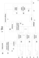
- FIG. 1 is a block diagram of a charging system according to an embodiment of the present disclosure.
- FIG. 1 is a block diagram of a charging system according to an embodiment of the present disclosure.
- the charging system 1 of the present disclosure can be for example but not limited to an electric-vehicle charging station.
- the charging system 1 includes a power input part 2, an inverter 3, a DC bus DCBUS, at least one charging device 4, a first bidirectional energy storage module 5, a second bidirectional energy storage module 6 and an intelligent controller 7.
- the power input part 2 is electrically connected to a power grid 10 and configured to output an AC input power.
- the power input part 2 includes a power conversion system (PCS) 20, a transformer device TR and a backup battery 21.
- the transformer device TR is electrically connected between an input terminal and an output terminal of the power input part 2.
- the transformer device TR includes a transformer.
- the power conversion system 20 includes an energy storage bidirectional converter, and is electrically connected between the backup battery 21 and the transformer device TR.
- the power conversion system 20 receives and converts the electric energy provided by the power grid 10 through the transformer device TR, so as to charge the backup battery 21.
- the power conversion system 20 converts the electric energy of the backup battery 21, and provides the converted electric energy to the output terminal of the power input part 2 through the transformer device TR, so that the AC input power is provided by the power input part 2 to the inverter 3.
- the inverter 3 is electrically connected between the output terminal of the power input part 2 and the DC bus DCBUS and configured to convert the AC input power provided by the power input part 2 into a DC power.
- the inverter 3 is a solid-state transformer (SST).
- the number of the charging device 4 can be one or more than one.
- the charging system 1 includes a plurality of charging devices 4.
- Each charging device 4 is electrically connected to the DC bus DCBUS.
- the charging device 4 is configured to convert a received electric energy, for example the DC power provided by the inverter 3, to charge a load. Therefore, when the load, such as an electric vehicle, is connected to the charging device 4, the load is charged by the charging device 4.
- each charging device 4 includes a DC/DC converter 40 and a charging gun 41.
- the DC/DC converter 40 is electrically connected between the DC bus DCBUS and the charging gun 41 and configured to convert the received DC power into another DC power at different voltage level, so as to provide to the charging gun 41.
- the charging gun 41 is electrically connected to the DC/DC converter 40. Moreover, the charging gun 41 is selectively connected to a load, and provides the DC power outputted from the DC/DC converter 40 to the load, so as to charge the load. In addition, when the controller (not shown) of the load and the charging system 1, such as the intelligent controller 7 of the charging system 1, reach an agreement (coordination) on the charging demand and the power supply capacity of the charging system 1 through communication, the charging system 1 is allowed to charge the load.
- the first bidirectional energy storage module 5 is electrically connected to the inverter 3 and the DC/DC converters 40 of the plurality of charging devices 4 through the DC bus DCBUS. Moreover, the first bidirectional energy storage module 5 is configured to receive the DC power provided by the inverter 3 through the DC bus DCBUS for charging, or configured to provide a first storage electric energy to the DC/DC converter 40 of the charging device 4 through the DC bus DCBUS. In some embodiments, the first bidirectional energy storage module 5 includes a first battery 50 and a first bidirectional DC/DC converter 51. The first bidirectional DC/DC converter 51 is electrically connected between the DC bus DCBUS and the first battery 50.
- the first bidirectional DC/DC converter 51 receives and converts the DC power provided by the inverter 3 through the DC bus DCBUS for charging the first battery 50, or the first bidirectional DC/DC converter 51 converts the first storage electric energy of the first battery 50 for delivering to the DC/DC converter 40 of the at least one charging device 4 through the DC bus DCBUS.
- the second bidirectional energy storage module 6 is electrically connected to the DC/DC converter 40 of the at least one charging device 4. Moreover, the second bidirectional energy storage module 6 is configured to receive the DC electric energy outputted by the DC/DC converter 40 for charging, or configured to provide a second storage electric energy for the charging device 4.
- the second bidirectional energy storage module 6 includes a second battery 60 and a second bidirectional DC/DC converter 61. The second bidirectional DC/DC converter 61 is electrically connected between the charging device 4 and the second battery 60.
- the second bidirectional DC/DC converter 61 receives and converts the DC electric energy outputted by the DC/DC converter 40 of the at least one charging device 4 for charging the second battery 60, or the second bidirectional DC/DC converter 61 converts the second storage electric energy of the second battery 60 for providing to the charging gun 41 of the at least one charging device 4 through the DC/DC converter 40 corresponding thereto.
- the intelligent controller 7 is electrically connected to the power input part 2, the first bidirectional energy storage module 5 and the second bidirectional energy storage module 6.
- the intelligent controller 7 is configured to control operations of the first bidirectional DC/DC converter 51 of the first bidirectional energy storage module 5 and the second bidirectional DC/DC converter 61 of the second bidirectional energy storage module 6.
- the intelligent controller 7 is configured to detect the operation condition (i.e., normal or abnormal) of the power grid 10, a first storage electricity value of the first battery 50 and a second storage electricity value of the second battery 60.
- the intelligent controller 7 is configured to receive an electricity price information from the power company through a wired communication transmission or a wireless communication transmission (not shown).
- the intelligent controller 7 is electrically connected to the charging gun 41.
- the intelligent controller 7 When the charging gun 41 is connected to the load, the intelligent controller 7 receives a charge demand information from the load through the charging gun 41.
- the intelligent controller 7 controls the operations of the first bidirectional DC/DC converter 51 and the second bidirectional DC/DC converter 61 in accordance with at least one of the operation condition of the power grid 10, the first storage electricity value of the first battery 50, the second storage electricity value of the second battery 60, the electricity price information and the charge demand information of the load.
- the intelligent controller 7 when the intelligent controller 7 detects that the operation condition of the power grid 10 is normal and detects that the second storage electricity value of the second battery 60 is greater than a preset first electricity threshold value, which represents that the second battery 60 is fully charged, and the charging demand information of the load indicates that the load connected to the charging gun 41 needs to be charged in high power, the intelligent controller 7 controls the second bidirectional DC/DC converter 61 to convert the second storage electric energy of the second battery 60 at maximum power, and provides it to the charging gun 41 through the DC/DC converter 40 corresponding thereto.
- the charging gun 41 connected with the load receives the electric energy converted from the second bidirectional DC/DC converter 61, or receives the sum of the electric energy converted form the second bidirectional DC/DC converter 61 and the electric energy converted from the DC/DC converter 40 of the charging device 4.
- the intelligent controller 7 when the intelligent controller 7 detects that the operation condition of the power grid 10 is normal and detects that the second storage electricity value of the second battery 60 is less than the first electricity threshold value and greater than a second electricity threshold value, the intelligent controller 7 controls the operation of the second bidirectional DC/DC converter 61 in accordance with the electricity price information.
- the electricity price information indicates that a current electricity price is greater than a preset electricity price
- the intelligent controller 7 controls the second bidirectional DC/DC converter 61 to stop the operation. In that, the DC electric energy outputted from the DC/DC converter 40 is not converted and the second battery 60 is not charged.
- the intelligent controller 7 controls the operation of the second bidirectional DC/DC converter 61 to convert the DC electric energy output by the DC/DC converter 40 of the at least one charging device 4, so that the second battery 60 is charged.
- the intelligent controller 7 when the intelligent controller 7 detects that the operation condition of the power grid 10 is abnormal, for example in the even of emergency power failure, the intelligent controller 7 controls the first bidirectional DC/DC converter 51 to convert the first storage electric energy of the first battery 50, and deliver to the DC/DC converter 40 of the charging device 4 through the DC bus DCBUS. Meanwhile, the intelligent controller 7 further detects whether the second storage electricity value of the second battery 60 is lower than the second electricity threshold value. When the second electricity value of the second battery 60 is greater than or equal to the second electricity threshold value, the intelligent controller 7 controls the second bidirectional DC/DC converter 61 to convert the second storage electric energy of the second battery 60, and provides it to the charging gun 41 through the DC/DC converter 40 corresponding thereto. When the second electricity value of the second battery 60 is less than the second electricity threshold value, the intelligent controller 7 controls the second bidirectional DC/DC converter 61 to stop the operation, and the second storage electric energy of the second battery 60 is not converted.
- the intelligent controller 7 when the intelligent controller 7 detects that the second electricity value of the second battery 60 is less than a preset second electricity threshold value, the intelligent controller 7 controls the second bidirectional DC/DC converter 61 to convert the DC electric energy provided by the first bidirectional DC/DC converter 51 for charging the second battery 60. Till the second electricity value of the second battery 60 is greater than or equal to the second electricity threshold value, the intelligent controller 7 controls the second bidirectional DC/DC converter 61 to stop the operation, so as to stop charging the second battery 60.
- the charging system 1 further includes a dispenser 8.
- the dispenser 8 is electrically connected to the DC/DC converters 40 of the plurality of charging devices 4, and the second bidirectional DC/DC converter 61 of the second bidirectional energy storage module 6.
- the disperser 8 includes a switch array (not shown), and each switch in the switch array is electrically connected between the second bidirectional DC/DC convert 61 of the second bidirectional energy storage module 6 and the DC/DC converter 40 of the charging device 4 corresponding thereto.
- each switch of the dispenser 8 is turned on or turned off under control of the intelligent controller 7.
- the intelligent controller 7 controls the disperser 8 to select one of the DC/DC converters 40 of the plurality of charging devices 4 to conduct with the second bidirectional DC/DC converter 61 of the second bidirectional energy storage module 6, so as to provide a charging or discharging path of the second battery 60.
- the second bidirectional DC/DC converter 61 can be for example but not limited to a non-isolated converter, which includes a non-isolated circuit.
- the isolation is ensured by the switch array of the dispenser 8.
- the isolation of the power grid 10 is provided by the inverter 3.
- the second battery 60 and the second bidirectional DC/DC converter 61 are integrated in the second bidirectional energy storage module 6. In other embodiments, the second battery 60 and the second bidirectional DC/DC converter 61 are disposed independently.
- the capacity of the first battery 51 is greater than or equal to the capacity of the second battery 61.
- the first battery 51 is an energy-type battery, which has high energy storage capacity.
- the second battery 61 is a power-type battery with high power for charging and discharging.
- the present disclosure provides a charging system.
- the charging system further includes a second bidirectional energy storage module.
- the charging system allows the second bidirectional DC/DC converter of the second bidirectional energy storage module to convert the second storage electric energy of the second battery at maximum power, and provides it to the charging gun through the DC/DC converter corresponding thereto, so that the charging system can provide high-power fast-charging function through the second bidirectional energy storage module.
- the maximum charging power of the charging system is not limited by the power grid connected thereto.
- the electric energy provided by the second bidirectional energy storage module is directly delivered to the charging gun through the DC/DC converter instead of passing through the inverter, it avoids the delivery through the multiple converters, so that the power loss of the charging system is reduced.
Landscapes
- Engineering & Computer Science (AREA)
- Power Engineering (AREA)
- Business, Economics & Management (AREA)
- Transportation (AREA)
- Mechanical Engineering (AREA)
- Strategic Management (AREA)
- Development Economics (AREA)
- Economics (AREA)
- Theoretical Computer Science (AREA)
- General Business, Economics & Management (AREA)
- Finance (AREA)
- Marketing (AREA)
- Accounting & Taxation (AREA)
- Health & Medical Sciences (AREA)
- General Physics & Mathematics (AREA)
- Physics & Mathematics (AREA)
- Water Supply & Treatment (AREA)
- Tourism & Hospitality (AREA)
- Public Health (AREA)
- General Health & Medical Sciences (AREA)
- Primary Health Care (AREA)
- Entrepreneurship & Innovation (AREA)
- Human Resources & Organizations (AREA)
- Game Theory and Decision Science (AREA)
- Charge And Discharge Circuits For Batteries Or The Like (AREA)
- Electric Propulsion And Braking For Vehicles (AREA)
Abstract
Description
- The present disclosure relates to a charging system, and more particularly to a charging system capable of reducing the power loss, reducing the power supply cost, and providing a high-power fast-charging function.
- Gasoline has been used as the main power source for the automobiles and motorcycles in the long term. In recent years, due to the promotion of environmental awareness and a large number of discussions on issues of limited resources, people have begun to consider about a new generation of vehicles, and electric vehicles are currently gaining more and more attention. It is hoped that the problems of environmental protection and limited resources are solved through the development of electric vehicles.
- At present, the manufacturing technology of electric vehicles on the market is increasingly developed as a mature technology. Therefore, the electric vehicles bound to become the mainstream in the future. In addition, the charging system (i.e., the charging station) for providing the power source of electric vehicles has also been widely installed gradually.
- However, since the conventional charging system has to provide the charging electric energy to the electric vehicle through a plurality of power stage converters, a large amount of power loss is resulted in the charging system. Furthermore, since the cost of electric energy is high, the aforementioned power loss resulted in the charging system will lead to additional power supply cost in the charging system. In addition, since the maximum charging power of the conventional charging system is limited by the grid connection installed, it fails to provide a high-power fast-charging function effectively.
- Therefore, there is a need of providing a charging system capable of reducing the power loss, reducing the power supply cost, and providing a high-power fast-charging function, so as to obviate the drawbacks encountered by the prior arts.
- An object of the present disclosure is to provide a charging system. In addition to a first bidirectional energy storage module, the charging system further includes a second bidirectional energy storage module, so as to use the above-mentioned bidirectional energy storage modules to achieve the advantages of reducing the power loss, reducing the power supply costs and providing the high-power fast-charging function.
- In accordance with an aspect of the present disclosure, a charging system is provided. The charging system includes a power input part, an inverter, a DC bus, at least one charging device, a first bidirectional energy storage module, a second bidirectional energy storage module and an intelligent controller. The power input part is electrically connected to a power grid for outputting an AC input power. The inverter is electrically connected to the power input part for converting the AC input power into a DC power. The DC bus is electrically connected to the inverter. The at least one charging device is electrically connected to the DC bus and includes a DC/DC converter and a charging gun, wherein the DC/DC converter is electrically connected between the DC bus and the charging gun. The first bidirectional energy storage module includes a first battery and a first bidirectional DC/DC converter, wherein the first bidirectional DC/DC converter is electrically connected between the DC bus and the first battery. The first bidirectional DC/DC converter is configured to receive and convert the DC power provided by the inverter through the DC bus for charging the first battery, or convert a first storage electric energy of the first battery for delivering to the DC/DC converter of the at least one charging device through the DC bus. The second bidirectional energy storage module includes a second battery and a second bidirectional DC/DC converter, wherein the second bidirectional DC/DC converter is electrically connected between the at least one charging device and the second battery. The second bidirectional DC/DC converter is configured to receive and convert the electric energy outputted by the DC/DC converter of the at least one charging device for charging the second battery, or convert a second storage electric energy of the second battery for providing to the charging gun of the at least one charging device through the DC/DC converter corresponding thereto. The intelligent controller is electrically connected to the power input part, the first bidirectional energy storage module and the second bidirectional energy storage module, wherein the intelligent controller controls operations of the first bidirectional DC/DC converter and the second bidirectional DC/DC converter in accordance with at least one of an operation condition of the power grid, a first storage electricity value of the first battery, a second storage electricity value of the second battery, an electricity price information and a charge demand information of a load.
- The above contents of the present disclosure will become more readily apparent to those ordinarily skilled in the art after reviewing the following detailed description and accompanying drawings, in which:
FIG. 1 is a block diagram of a charging system according to an embodiment of the present disclosure. - The present disclosure will now be described more specifically with reference to the following embodiments. It is to be noted that the following descriptions of preferred embodiments of this disclosure are presented herein for purpose of illustration and description only. It is not intended to be exhaustive or to be limited to the precise form disclosed.
- Please refer to
FIG. 1. FIG. 1 is a block diagram of a charging system according to an embodiment of the present disclosure. As shown inFIG. 1 , thecharging system 1 of the present disclosure can be for example but not limited to an electric-vehicle charging station. In the embodiment, thecharging system 1 includes apower input part 2, aninverter 3, a DC bus DCBUS, at least onecharging device 4, a first bidirectionalenergy storage module 5, a second bidirectionalenergy storage module 6 and anintelligent controller 7. - In the embodiment, the
power input part 2 is electrically connected to apower grid 10 and configured to output an AC input power. When the operation condition of thepower grid 10 is normal, the AC input power outputted by thepower input part 2 is provided through thepower grid 10. In the embodiment, thepower input part 2 includes a power conversion system (PCS) 20, a transformer device TR and abackup battery 21. The transformer device TR is electrically connected between an input terminal and an output terminal of thepower input part 2. Preferably but not exclusively, the transformer device TR includes a transformer. Thepower conversion system 20 includes an energy storage bidirectional converter, and is electrically connected between thebackup battery 21 and the transformer device TR. When the operation condition of thepower grid 10 is normal, thepower conversion system 20 receives and converts the electric energy provided by thepower grid 10 through the transformer device TR, so as to charge thebackup battery 21. When the operation condition of thepower grid 10 is abnormal, for example in the even of emergency power failure, thepower conversion system 20 converts the electric energy of thebackup battery 21, and provides the converted electric energy to the output terminal of thepower input part 2 through the transformer device TR, so that the AC input power is provided by thepower input part 2 to theinverter 3. - In the embodiment, the
inverter 3 is electrically connected between the output terminal of thepower input part 2 and the DC bus DCBUS and configured to convert the AC input power provided by thepower input part 2 into a DC power. Preferably but not exclusively, in some embodiments, theinverter 3 is a solid-state transformer (SST). - The number of the
charging device 4 can be one or more than one. In the embodiment, thecharging system 1 includes a plurality ofcharging devices 4. Eachcharging device 4 is electrically connected to the DC bus DCBUS. In the embodiment, thecharging device 4 is configured to convert a received electric energy, for example the DC power provided by theinverter 3, to charge a load. Therefore, when the load, such as an electric vehicle, is connected to thecharging device 4, the load is charged by thecharging device 4. In the embodiment, eachcharging device 4 includes a DC/DC converter 40 and acharging gun 41. The DC/DC converter 40 is electrically connected between the DC bus DCBUS and thecharging gun 41 and configured to convert the received DC power into another DC power at different voltage level, so as to provide to thecharging gun 41. Thecharging gun 41 is electrically connected to the DC/DC converter 40. Moreover, thecharging gun 41 is selectively connected to a load, and provides the DC power outputted from the DC/DC converter 40 to the load, so as to charge the load. In addition, when the controller (not shown) of the load and thecharging system 1, such as theintelligent controller 7 of thecharging system 1, reach an agreement (coordination) on the charging demand and the power supply capacity of thecharging system 1 through communication, thecharging system 1 is allowed to charge the load. - In the embodiment, the first bidirectional
energy storage module 5 is electrically connected to theinverter 3 and the DC/DC converters 40 of the plurality ofcharging devices 4 through the DC bus DCBUS. Moreover, the first bidirectionalenergy storage module 5 is configured to receive the DC power provided by theinverter 3 through the DC bus DCBUS for charging, or configured to provide a first storage electric energy to the DC/DC converter 40 of thecharging device 4 through the DC bus DCBUS. In some embodiments, the first bidirectionalenergy storage module 5 includes afirst battery 50 and a first bidirectional DC/DC converter 51. The first bidirectional DC/DC converter 51 is electrically connected between the DC bus DCBUS and thefirst battery 50. Preferably but not exclusively, the first bidirectional DC/DC converter 51 receives and converts the DC power provided by theinverter 3 through the DC bus DCBUS for charging thefirst battery 50, or the first bidirectional DC/DC converter 51 converts the first storage electric energy of thefirst battery 50 for delivering to the DC/DC converter 40 of the at least onecharging device 4 through the DC bus DCBUS. - Different from the first bidirectional
energy storage module 5 directly connected to the DC bus DCBUS, in the embodiment, the second bidirectionalenergy storage module 6 is electrically connected to the DC/DC converter 40 of the at least onecharging device 4. Moreover, the second bidirectionalenergy storage module 6 is configured to receive the DC electric energy outputted by the DC/DC converter 40 for charging, or configured to provide a second storage electric energy for thecharging device 4. In some embodiments, the second bidirectionalenergy storage module 6 includes asecond battery 60 and a second bidirectional DC/DC converter 61. The second bidirectional DC/DC converter 61 is electrically connected between the chargingdevice 4 and thesecond battery 60. Preferably but not exclusively, the second bidirectional DC/DC converter 61 receives and converts the DC electric energy outputted by the DC/DC converter 40 of the at least onecharging device 4 for charging thesecond battery 60, or the second bidirectional DC/DC converter 61 converts the second storage electric energy of thesecond battery 60 for providing to the charginggun 41 of the at least onecharging device 4 through the DC/DC converter 40 corresponding thereto. - In the embodiment, the
intelligent controller 7 is electrically connected to thepower input part 2, the first bidirectionalenergy storage module 5 and the second bidirectionalenergy storage module 6. Theintelligent controller 7 is configured to control operations of the first bidirectional DC/DC converter 51 of the first bidirectionalenergy storage module 5 and the second bidirectional DC/DC converter 61 of the second bidirectionalenergy storage module 6. Moreover, theintelligent controller 7 is configured to detect the operation condition (i.e., normal or abnormal) of thepower grid 10, a first storage electricity value of thefirst battery 50 and a second storage electricity value of thesecond battery 60. In addition, theintelligent controller 7 is configured to receive an electricity price information from the power company through a wired communication transmission or a wireless communication transmission (not shown). Furthermore, theintelligent controller 7 is electrically connected to the charginggun 41. When the charginggun 41 is connected to the load, theintelligent controller 7 receives a charge demand information from the load through the charginggun 41. In the embodiment, theintelligent controller 7 controls the operations of the first bidirectional DC/DC converter 51 and the second bidirectional DC/DC converter 61 in accordance with at least one of the operation condition of thepower grid 10, the first storage electricity value of thefirst battery 50, the second storage electricity value of thesecond battery 60, the electricity price information and the charge demand information of the load. - In the embodiment, when the
intelligent controller 7 detects that the operation condition of thepower grid 10 is normal and detects that the second storage electricity value of thesecond battery 60 is greater than a preset first electricity threshold value, which represents that thesecond battery 60 is fully charged, and the charging demand information of the load indicates that the load connected to the charginggun 41 needs to be charged in high power, theintelligent controller 7 controls the second bidirectional DC/DC converter 61 to convert the second storage electric energy of thesecond battery 60 at maximum power, and provides it to the charginggun 41 through the DC/DC converter 40 corresponding thereto. Meanwhile, the charginggun 41 connected with the load receives the electric energy converted from the second bidirectional DC/DC converter 61, or receives the sum of the electric energy converted form the second bidirectional DC/DC converter 61 and the electric energy converted from the DC/DC converter 40 of thecharging device 4. - In the embodiment, when the
intelligent controller 7 detects that the operation condition of thepower grid 10 is normal and detects that the second storage electricity value of thesecond battery 60 is less than the first electricity threshold value and greater than a second electricity threshold value, theintelligent controller 7 controls the operation of the second bidirectional DC/DC converter 61 in accordance with the electricity price information. When the electricity price information indicates that a current electricity price is greater than a preset electricity price, theintelligent controller 7 controls the second bidirectional DC/DC converter 61 to stop the operation. In that, the DC electric energy outputted from the DC/DC converter 40 is not converted and thesecond battery 60 is not charged. When the electricity price information indicates that the current electricity price is less than or equal to the preset electricity price, theintelligent controller 7 controls the operation of the second bidirectional DC/DC converter 61 to convert the DC electric energy output by the DC/DC converter 40 of the at least onecharging device 4, so that thesecond battery 60 is charged. - In the embodiment, when the
intelligent controller 7 detects that the operation condition of thepower grid 10 is abnormal, for example in the even of emergency power failure, theintelligent controller 7 controls the first bidirectional DC/DC converter 51 to convert the first storage electric energy of thefirst battery 50, and deliver to the DC/DC converter 40 of thecharging device 4 through the DC bus DCBUS. Meanwhile, theintelligent controller 7 further detects whether the second storage electricity value of thesecond battery 60 is lower than the second electricity threshold value. When the second electricity value of thesecond battery 60 is greater than or equal to the second electricity threshold value, theintelligent controller 7 controls the second bidirectional DC/DC converter 61 to convert the second storage electric energy of thesecond battery 60, and provides it to the charginggun 41 through the DC/DC converter 40 corresponding thereto. When the second electricity value of thesecond battery 60 is less than the second electricity threshold value, theintelligent controller 7 controls the second bidirectional DC/DC converter 61 to stop the operation, and the second storage electric energy of thesecond battery 60 is not converted. - In the embodiment, when the
intelligent controller 7 detects that the second electricity value of thesecond battery 60 is less than a preset second electricity threshold value, theintelligent controller 7 controls the second bidirectional DC/DC converter 61 to convert the DC electric energy provided by the first bidirectional DC/DC converter 51 for charging thesecond battery 60. Till the second electricity value of thesecond battery 60 is greater than or equal to the second electricity threshold value, theintelligent controller 7 controls the second bidirectional DC/DC converter 61 to stop the operation, so as to stop charging thesecond battery 60. - In some embodiments, the
charging system 1 further includes a dispenser 8. The dispenser 8 is electrically connected to the DC/DC converters 40 of the plurality of chargingdevices 4, and the second bidirectional DC/DC converter 61 of the second bidirectionalenergy storage module 6. Preferably but not exclusively, the disperser 8 includes a switch array (not shown), and each switch in the switch array is electrically connected between the second bidirectional DC/DC convert 61 of the second bidirectionalenergy storage module 6 and the DC/DC converter 40 of thecharging device 4 corresponding thereto. In the embodiment, each switch of the dispenser 8 is turned on or turned off under control of theintelligent controller 7. In that, theintelligent controller 7 controls the disperser 8 to select one of the DC/DC converters 40 of the plurality of chargingdevices 4 to conduct with the second bidirectional DC/DC converter 61 of the second bidirectionalenergy storage module 6, so as to provide a charging or discharging path of thesecond battery 60. - In some embodiments, since the second bidirectional
energy storage module 6 is allowed to charge a single load at one time, the second bidirectional DC/DC converter 61 can be for example but not limited to a non-isolated converter, which includes a non-isolated circuit. Preferably but not exclusively, the isolation is ensured by the switch array of the dispenser 8. In addition, when thesecond battery 60 is charged, the isolation of thepower grid 10 is provided by theinverter 3. - In some embodiments, the
second battery 60 and the second bidirectional DC/DC converter 61 are integrated in the second bidirectionalenergy storage module 6. In other embodiments, thesecond battery 60 and the second bidirectional DC/DC converter 61 are disposed independently. - Preferably but not exclusively, in some embodiments, the capacity of the
first battery 51 is greater than or equal to the capacity of thesecond battery 61. Preferably but not exclusively, thefirst battery 51 is an energy-type battery, which has high energy storage capacity. Preferably but not exclusively, thesecond battery 61 is a power-type battery with high power for charging and discharging. - In summary, the present disclosure provides a charging system. In addition to a first bidirectional energy storage module, the charging system further includes a second bidirectional energy storage module. When the load connected to the charging gun needs to be charged with high power, the charging system allows the second bidirectional DC/DC converter of the second bidirectional energy storage module to convert the second storage electric energy of the second battery at maximum power, and provides it to the charging gun through the DC/DC converter corresponding thereto, so that the charging system can provide high-power fast-charging function through the second bidirectional energy storage module. Moreover, the maximum charging power of the charging system is not limited by the power grid connected thereto. Furthermore, since the electric energy provided by the second bidirectional energy storage module is directly delivered to the charging gun through the DC/DC converter instead of passing through the inverter, it avoids the delivery through the multiple converters, so that the power loss of the charging system is reduced.
- While the disclosure has been described in terms of what is presently considered to be the most practical and preferred embodiments, it is to be understood that the disclosure needs not be limited to the disclosed embodiment. On the contrary, it is intended to cover various modifications and similar arrangements included within the spirit and scope of the appended claims which are to be accorded with the broadest interpretation so as to encompass all such modifications and similar structures.
Claims (11)
- A charging system (1) characterized by comprising:a power input part (2) electrically connected to a power grid (10) for outputting an AC input power;an inverter (3) electrically connected to the power input part (2) for converting the AC input power into a DC power;a DC bus (DCBUS) electrically connected to the inverter (3);at least one charging device (4) comprising a DC/DC converter (40) and a charging gun (41), wherein the DC/DC converter (40) is electrically connected between the DC bus (DCBUS) and the charging gun (41);a first bidirectional energy storage module (5) comprising a first battery (50) and a first bidirectional DC/DC converter (51), wherein the first bidirectional DC/DC converter (51) is electrically connected between the DC bus (DCBUS) and the first battery (50), and the first bidirectional DC/DC converter (51) is configured to receive and convert the DC power provided by the inverter (3) through the DC bus (DCBUS) for charging the first battery (50), or convert a first storage electric energy of the first battery (50) for delivering to the DC/DC converter (40) of the at least one charging device (4) through the DC bus (DCBUS);a second bidirectional energy storage module (6) comprising a second battery (60) and a second bidirectional DC/DC converter (61), wherein the second bidirectional DC/DC converter (61) is electrically connected between the at least one charging device (4) and the second battery (60), and the second bidirectional DC/DC converter (61) is configured to receive and convert an electric energy outputted by the DC/DC converter (40) of the at least one charging device (4) for charging the second battery (60), or convert a second storage electric energy of the second battery (60) for providing to the charging gun (41) of the at least one charging device (4) through the DC/DC converter (40) corresponding thereto; andan intelligent controller (7) electrically connected to the power input part (2), the first bidirectional energy storage module (5) and the second bidirectional energy storage module (6).
- The charging system (1) according to claim 1, wherein when the intelligent controller (7) detects that an operation condition of the power grid (10) is normal and detects that the second storage electricity value of the second battery (60) is greater than a first electricity threshold value, and the charging demand information of a load indicates that the load connected to the charging gun (41) needs to be charged in high power, the intelligent controller (7) controls the second bidirectional DC/DC converter (61) to convert the second storage electric energy of the second battery (60) at maximum power.
- The charging system (1) according to claim 1, wherein when the intelligent controller (7) detects that the operation condition of the power grid (10) is normal and detects that the second storage electricity value of the second battery (60) is less than a first electricity threshold value and greater than a second electricity threshold value, the intelligent controller (7) controls the operation of the second bidirectional DC/DC convertor (61) in accordance with an electricity price information.
- The charging system (1) according to claim 3, wherein when the electricity price information indicates that a current electricity price is greater than a preset electricity price, the intelligent controller (7) controls the second bidirectional DC/DC converter (61) to stop the operation, wherein when the electricity price information indicates that the current electricity price is less than or equal to the preset electricity price, the intelligent controller (7) controls the operation of the second bidirectional DC/DC converter (61) to convert the electric energy output by the DC/DC converter (40) of the at least one charging device (4) for charging the second battery (60).
- The charging system (1) according to claim 1, wherein when the intelligent controller (7) detects that the operation condition of the power grid (10) is abnormal, the intelligent controller (7) controls the first bidirectional DC/DC converter (5) to convert the first storage electric energy of the first battery (50), and the intelligent controller (7) further detects whether the second storage electricity value of the second battery (60) is lower than a second electricity threshold value, wherein when the second electricity value of the second battery (60) is greater than or equal to the second electricity threshold value, the intelligent controller (7) controls the second bidirectional DC/DC converter (61) to convert the second storage electric energy of the second battery (60), wherein when the second electricity value of the second battery (60) is less than the second electricity threshold value, the intelligent controller (7) controls the second bidirectional DC/DC converter (61) to stop the operation.
- The charging system (1) according to claim 1, wherein when the intelligent controller (7) detects that the second electricity value of the second battery (60) is less than a second electricity threshold value, the intelligent controller (7) controls the second bidirectional DC/DC converter (61) to convert the electric energy provided by the first bidirectional DC/DC converter (51) for charging the second battery (60), and till the second electricity value of the second battery (60) is greater than or equal to the second electricity threshold value, the intelligent controller (7) controls the second bidirectional DC/DC converter (61) to stop the operation.
- The charging system (1) according to claim 1, wherein the at least one charging device (4) includes a plurality of charging devices (4), and the charging system (1) further comprises a dispenser (8) electrically connected to the DC/DC converters (40) of the plurality of charging devices (4) and the second bidirectional DC/DC converter (61) of the second bidirectional energy storage module (6), wherein the intelligent controller (7) controls the dispenser (8) to select one of the DC/DC converters (40) of the plurality of charging devices (4) to conduct with the second bidirectional DC/DC converter (61) of the second bidirectional energy storage module (6) to provide a charging or discharging path of the second battery (60).
- The charging system (1) according to claim 1, wherein the capacity of the first battery (50) is greater than or equal to the capacity of the second battery (60).
- The charging system (1) according to claim 1, wherein the first battery (50) is an energy-type battery, and the second battery (60) is a power-type battery.
- The charging system (1) according to claim 1, wherein the second bidirectional DC/DC converter (61) is a non-isolated converter.
- The charging system (1) according to claim 1, wherein the intelligent controller (7) controls operations of the first bidirectional DC/DC converter (51) and the second bidirectional DC/DC converter (61) in accordance with at least one of an operation condition of the power grid (10), a first storage electricity value of the first battery (50), a second storage electricity value of the second battery (60), an electricity price information and a charge demand information of a load.
Applications Claiming Priority (1)
| Application Number | Priority Date | Filing Date | Title |
|---|---|---|---|
| US18/098,062 US12068632B2 (en) | 2023-01-17 | 2023-01-17 | Charging system |
Publications (1)
| Publication Number | Publication Date |
|---|---|
| EP4404414A1 true EP4404414A1 (en) | 2024-07-24 |
Family
ID=85601487
Family Applications (1)
| Application Number | Title | Priority Date | Filing Date |
|---|---|---|---|
| EP23161465.2A Pending EP4404414A1 (en) | 2023-01-17 | 2023-03-13 | Charging system |
Country Status (7)
| Country | Link |
|---|---|
| US (2) | US12068632B2 (en) |
| EP (1) | EP4404414A1 (en) |
| JP (1) | JP7518237B1 (en) |
| CN (1) | CN118358414A (en) |
| AU (1) | AU2023425467A1 (en) |
| TW (1) | TWI846346B (en) |
| WO (1) | WO2024152507A1 (en) |
Families Citing this family (4)
| Publication number | Priority date | Publication date | Assignee | Title |
|---|---|---|---|---|
| US12068632B2 (en) * | 2023-01-17 | 2024-08-20 | Delta Electronics, Inc. | Charging system |
| US20250121737A1 (en) * | 2023-10-12 | 2025-04-17 | Ford Global Technologies, Llc | Control and management of upfitter and vehicle loads |
| CN119160028B (en) * | 2024-11-18 | 2025-04-29 | 宁德时代新能源科技股份有限公司 | Charging system, charging control method and charging pile |
| CN120527870A (en) * | 2025-07-09 | 2025-08-22 | 广东省特种设备检测研究院中山检测院 | Energy-saving device for frequency converter, energy control method and lifting equipment |
Citations (4)
| Publication number | Priority date | Publication date | Assignee | Title |
|---|---|---|---|---|
| US20040130292A1 (en) * | 2000-06-14 | 2004-07-08 | Buchanan William D. | Battery charging system and method |
| EP2848457A2 (en) * | 2013-09-11 | 2015-03-18 | Proterra Inc | Methods and systems for electric vehicle charging |
| US20180339595A1 (en) * | 2017-05-23 | 2018-11-29 | Delta Electronics, Inc. | Electric vehicle charging circuit and control method thereof |
| CN112821457A (en) * | 2021-02-26 | 2021-05-18 | 黄俊星 | Storage and charging integrated power system |
Family Cites Families (31)
| Publication number | Priority date | Publication date | Assignee | Title |
|---|---|---|---|---|
| JPH0965509A (en) * | 1995-06-14 | 1997-03-07 | Toyota Autom Loom Works Ltd | Electric vehicle battery charging method and electric vehicle charger |
| US20080039979A1 (en) * | 2006-08-10 | 2008-02-14 | V2 Green Inc. | Smart Islanding and Power Backup in a Power Aggregation System for Distributed Electric Resources |
| US20130221918A1 (en) | 2010-04-26 | 2013-08-29 | Proterra Inc | Fast charge stations for electric vehicles in areas with limited power availabilty |
| JP2013081289A (en) * | 2011-10-03 | 2013-05-02 | Panasonic Corp | Power controller |
| US9381826B2 (en) | 2012-10-19 | 2016-07-05 | Gogoro Inc. | Battery configuration for an electric vehicle |
| JP6201319B2 (en) | 2013-01-15 | 2017-09-27 | 住友電気工業株式会社 | Converter, failure determination method, and control program |
| CN206947969U (en) | 2017-04-12 | 2018-01-30 | 蔚来汽车有限公司 | Electric mobile charging vehicle |
| TW201919303A (en) | 2017-11-14 | 2019-05-16 | 曾鴻輝 | System and method of charging for electric vehicle |
| US11532946B2 (en) * | 2017-11-30 | 2022-12-20 | The Board Of Trustees Of The University Of Alabama | Power electronics charge coupler for vehicle-to-vehicle fast energy sharing |
| DE102017128573B3 (en) | 2017-12-01 | 2019-01-31 | Scienlab Beteiligungsgesellschaft Mbh | Charging arrangement for an electric vehicle on a medium-voltage network and method for its operation |
| CN108146284A (en) | 2018-01-09 | 2018-06-12 | 郑宏 | A kind of fixing type electric charging equipment for automobile and its charging method |
| US11594883B2 (en) * | 2018-01-23 | 2023-02-28 | Tdk Corporation | Direct current power supplying system |
| EP3543063B1 (en) * | 2018-03-19 | 2023-06-07 | Volvo Car Corporation | High voltage electrical system for a vehicle and method of controlling the system |
| JP6811219B2 (en) | 2018-09-13 | 2021-01-13 | 矢崎総業株式会社 | Vehicle power supply |
| WO2020056534A1 (en) | 2018-09-21 | 2020-03-26 | Universidad Técnica Federico Santa María | Transformerless partial power converter (ppc) for the dc-dc stage of rapid-charging stations for electric vehicles (ev) |
| US11084388B2 (en) | 2019-05-13 | 2021-08-10 | James Nguyen | Fast charging battery pack and methods to charge fast |
| WO2021044955A1 (en) | 2019-09-02 | 2021-03-11 | パナソニックIpマネジメント株式会社 | Power conversion system and method of constructing power conversion system |
| CN114728600A (en) * | 2019-09-13 | 2022-07-08 | 埃内尔克斯维美国公司 | High-power bidirectional power grid connected charger with split battery architecture |
| CN110474356B (en) | 2019-09-15 | 2024-08-20 | 长园深瑞继保自动化有限公司 | A charging and storage integrated method and system based on a multiplexed bidirectional DCDC converter |
| JP2021097463A (en) * | 2019-12-16 | 2021-06-24 | 古河電気工業株式会社 | Charger and charging method |
| CN112421739B (en) | 2020-04-24 | 2024-01-02 | 葛炽昌 | Electric vehicle AC charging system |
| JP2021191140A (en) | 2020-06-01 | 2021-12-13 | 株式会社アイチコーポレーション | Moving body power storage and supply system |
| US11594973B2 (en) * | 2020-08-04 | 2023-02-28 | Delta Electronics Inc. | Multiple-port bidirectional converter and control method thereof |
| CN112186790A (en) | 2020-09-28 | 2021-01-05 | 北华航天工业学院 | Electric automobile and power grid V2G bidirectional power flow control system and method |
| CN113422372A (en) | 2020-12-22 | 2021-09-21 | 北京信息科技大学 | Integrated charging station for transformer substation and control method |
| CN214984931U (en) | 2021-04-28 | 2021-12-03 | 青岛特来电新能源科技有限公司 | Charging terminal, equipment, system, charging station and energy storage package |
| US20220396167A1 (en) * | 2021-06-09 | 2022-12-15 | Bahman Sharifipour | Electric vehicle solar charging system |
| CN113859009A (en) | 2021-09-27 | 2021-12-31 | 国网北京市电力公司 | Charging pile power supply method and device, storage medium and processor |
| CN117183810B (en) * | 2022-05-31 | 2024-12-10 | 比亚迪股份有限公司 | Battery circuit and vehicle |
| CN116802956A (en) * | 2022-07-27 | 2023-09-22 | 宁德时代新能源科技股份有限公司 | Charge and discharge control methods, devices, equipment and storage media |
| US12068632B2 (en) * | 2023-01-17 | 2024-08-20 | Delta Electronics, Inc. | Charging system |
-
2023
- 2023-01-17 US US18/098,062 patent/US12068632B2/en active Active
- 2023-02-23 TW TW112106607A patent/TWI846346B/en active
- 2023-02-23 CN CN202310156732.9A patent/CN118358414A/en active Pending
- 2023-03-13 EP EP23161465.2A patent/EP4404414A1/en active Pending
- 2023-04-21 JP JP2023070136A patent/JP7518237B1/en active Active
- 2023-06-09 AU AU2023425467A patent/AU2023425467A1/en active Pending
- 2023-06-09 WO PCT/CN2023/099502 patent/WO2024152507A1/en not_active Ceased
-
2024
- 2024-07-16 US US18/774,507 patent/US20240372395A1/en active Pending
Patent Citations (4)
| Publication number | Priority date | Publication date | Assignee | Title |
|---|---|---|---|---|
| US20040130292A1 (en) * | 2000-06-14 | 2004-07-08 | Buchanan William D. | Battery charging system and method |
| EP2848457A2 (en) * | 2013-09-11 | 2015-03-18 | Proterra Inc | Methods and systems for electric vehicle charging |
| US20180339595A1 (en) * | 2017-05-23 | 2018-11-29 | Delta Electronics, Inc. | Electric vehicle charging circuit and control method thereof |
| CN112821457A (en) * | 2021-02-26 | 2021-05-18 | 黄俊星 | Storage and charging integrated power system |
Also Published As
| Publication number | Publication date |
|---|---|
| TWI846346B (en) | 2024-06-21 |
| TW202430394A (en) | 2024-08-01 |
| JP2024101510A (en) | 2024-07-29 |
| US12068632B2 (en) | 2024-08-20 |
| WO2024152507A1 (en) | 2024-07-25 |
| JP7518237B1 (en) | 2024-07-17 |
| AU2023425467A1 (en) | 2025-03-13 |
| US20240372395A1 (en) | 2024-11-07 |
| CN118358414A (en) | 2024-07-19 |
| US20240243603A1 (en) | 2024-07-18 |
Similar Documents
| Publication | Publication Date | Title |
|---|---|---|
| US12068632B2 (en) | Charging system | |
| EP3560749B1 (en) | Charging pile system | |
| US8269374B2 (en) | Solar panel power management system and method | |
| US20260025000A1 (en) | Control method of power supply circuit, power supply circuit, and energy storage device | |
| US12311795B2 (en) | Charging apparatus and method of operating the same | |
| CN214984931U (en) | Charging terminal, equipment, system, charging station and energy storage package | |
| KR20230088472A (en) | Battery formation device, control method of battery formation device, and control system | |
| WO2024041383A1 (en) | Energy storage system and power supply control method for battery management system | |
| CN117937664A (en) | Charging system and charging method | |
| WO2025232283A1 (en) | Charging apparatus | |
| US11230202B2 (en) | Multiple vehicle charging system | |
| KR102645452B1 (en) | Charge/discharge device, battery charging method, and charge/discharge system | |
| EP4335686B1 (en) | Fast charging system for electric vehicles with power dynamic distribution function | |
| EP4106140A1 (en) | Charging system utilizing energy storage multiplication | |
| CN105449720A (en) | a power distribution system | |
| KR20180099279A (en) | Energy storage system including energy storage device | |
| EP4560876A2 (en) | Charging connection apparatus and charging system | |
| WO2026001981A1 (en) | Battery pack, grid connection management method, electric energy device and energy storage system | |
| CN217240364U (en) | Energy storage charging system | |
| CN215042206U (en) | Energy storage package, vehicle charging equipment and charging station | |
| CN223957307U (en) | Photovoltaic energy storage charging integrated circuit and charging robot applying same | |
| CN114368293A (en) | Charging terminal, equipment, system, station, energy storage pack and charging control method | |
| CN222395451U (en) | A photovoltaic storage, charging and testing system for AC and DC power supply | |
| EP4556300A1 (en) | Power allocation apparatus and charging device | |
| CN115313612B (en) | 48V direct current reserve integrated power supply system, and charging and discharging control method and application thereof |
Legal Events
| Date | Code | Title | Description |
|---|---|---|---|
| PUAI | Public reference made under article 153(3) epc to a published international application that has entered the european phase |
Free format text: ORIGINAL CODE: 0009012 |
|
| STAA | Information on the status of an ep patent application or granted ep patent |
Free format text: STATUS: THE APPLICATION HAS BEEN PUBLISHED |
|
| AK | Designated contracting states |
Kind code of ref document: A1 Designated state(s): AL AT BE BG CH CY CZ DE DK EE ES FI FR GB GR HR HU IE IS IT LI LT LU LV MC ME MK MT NL NO PL PT RO RS SE SI SK SM TR |
|
| STAA | Information on the status of an ep patent application or granted ep patent |
Free format text: STATUS: REQUEST FOR EXAMINATION WAS MADE |
|
| 17P | Request for examination filed |
Effective date: 20240731 |
|
| RBV | Designated contracting states (corrected) |
Designated state(s): AL AT BE BG CH CY CZ DE DK EE ES FI FR GB GR HR HU IE IS IT LI LT LU LV MC ME MK MT NL NO PL PT RO RS SE SI SK SM TR |