EP4404358A1 - Pressure regulating valve for power storage module, and power storage unit - Google Patents
Pressure regulating valve for power storage module, and power storage unit Download PDFInfo
- Publication number
- EP4404358A1 EP4404358A1 EP22869717.3A EP22869717A EP4404358A1 EP 4404358 A1 EP4404358 A1 EP 4404358A1 EP 22869717 A EP22869717 A EP 22869717A EP 4404358 A1 EP4404358 A1 EP 4404358A1
- Authority
- EP
- European Patent Office
- Prior art keywords
- power storage
- regulating valve
- pressure
- storage module
- case
- Prior art date
- Legal status (The legal status is an assumption and is not a legal conclusion. Google has not performed a legal analysis and makes no representation as to the accuracy of the status listed.)
- Pending
Links
Images



Classifications
-
- H—ELECTRICITY
- H01—ELECTRIC ELEMENTS
- H01M—PROCESSES OR MEANS, e.g. BATTERIES, FOR THE DIRECT CONVERSION OF CHEMICAL ENERGY INTO ELECTRICAL ENERGY
- H01M50/00—Constructional details or processes of manufacture of the non-active parts of electrochemical cells other than fuel cells, e.g. hybrid cells
- H01M50/30—Arrangements for facilitating escape of gases
- H01M50/308—Detachable arrangements, e.g. detachable vent plugs or plug systems
-
- H—ELECTRICITY
- H01—ELECTRIC ELEMENTS
- H01M—PROCESSES OR MEANS, e.g. BATTERIES, FOR THE DIRECT CONVERSION OF CHEMICAL ENERGY INTO ELECTRICAL ENERGY
- H01M50/00—Constructional details or processes of manufacture of the non-active parts of electrochemical cells other than fuel cells, e.g. hybrid cells
- H01M50/20—Mountings; Secondary casings or frames; Racks, modules or packs; Suspension devices; Shock absorbers; Transport or carrying devices; Holders
- H01M50/204—Racks, modules or packs for multiple batteries or multiple cells
- H01M50/207—Racks, modules or packs for multiple batteries or multiple cells characterised by their shape
- H01M50/209—Racks, modules or packs for multiple batteries or multiple cells characterised by their shape adapted for prismatic or rectangular cells
-
- H—ELECTRICITY
- H01—ELECTRIC ELEMENTS
- H01M—PROCESSES OR MEANS, e.g. BATTERIES, FOR THE DIRECT CONVERSION OF CHEMICAL ENERGY INTO ELECTRICAL ENERGY
- H01M50/00—Constructional details or processes of manufacture of the non-active parts of electrochemical cells other than fuel cells, e.g. hybrid cells
- H01M50/30—Arrangements for facilitating escape of gases
- H01M50/317—Re-sealable arrangements
-
- H—ELECTRICITY
- H01—ELECTRIC ELEMENTS
- H01M—PROCESSES OR MEANS, e.g. BATTERIES, FOR THE DIRECT CONVERSION OF CHEMICAL ENERGY INTO ELECTRICAL ENERGY
- H01M50/00—Constructional details or processes of manufacture of the non-active parts of electrochemical cells other than fuel cells, e.g. hybrid cells
- H01M50/30—Arrangements for facilitating escape of gases
- H01M50/317—Re-sealable arrangements
- H01M50/325—Re-sealable arrangements comprising deformable valve members, e.g. elastic or flexible valve members
-
- H—ELECTRICITY
- H01—ELECTRIC ELEMENTS
- H01M—PROCESSES OR MEANS, e.g. BATTERIES, FOR THE DIRECT CONVERSION OF CHEMICAL ENERGY INTO ELECTRICAL ENERGY
- H01M50/00—Constructional details or processes of manufacture of the non-active parts of electrochemical cells other than fuel cells, e.g. hybrid cells
- H01M50/30—Arrangements for facilitating escape of gases
- H01M50/35—Gas exhaust passages comprising elongated, tortuous or labyrinth-shaped exhaust passages
- H01M50/358—External gas exhaust passages located on the battery cover or case
-
- H—ELECTRICITY
- H01—ELECTRIC ELEMENTS
- H01M—PROCESSES OR MEANS, e.g. BATTERIES, FOR THE DIRECT CONVERSION OF CHEMICAL ENERGY INTO ELECTRICAL ENERGY
- H01M2200/00—Safety devices for primary or secondary batteries
- H01M2200/20—Pressure-sensitive devices
-
- H—ELECTRICITY
- H01—ELECTRIC ELEMENTS
- H01M—PROCESSES OR MEANS, e.g. BATTERIES, FOR THE DIRECT CONVERSION OF CHEMICAL ENERGY INTO ELECTRICAL ENERGY
- H01M2220/00—Batteries for particular applications
- H01M2220/20—Batteries in motive systems, e.g. vehicle, ship, plane
-
- Y—GENERAL TAGGING OF NEW TECHNOLOGICAL DEVELOPMENTS; GENERAL TAGGING OF CROSS-SECTIONAL TECHNOLOGIES SPANNING OVER SEVERAL SECTIONS OF THE IPC; TECHNICAL SUBJECTS COVERED BY FORMER USPC CROSS-REFERENCE ART COLLECTIONS [XRACs] AND DIGESTS
- Y02—TECHNOLOGIES OR APPLICATIONS FOR MITIGATION OR ADAPTATION AGAINST CLIMATE CHANGE
- Y02E—REDUCTION OF GREENHOUSE GAS [GHG] EMISSIONS, RELATED TO ENERGY GENERATION, TRANSMISSION OR DISTRIBUTION
- Y02E60/00—Enabling technologies; Technologies with a potential or indirect contribution to GHG emissions mitigation
- Y02E60/10—Energy storage using batteries
Definitions
- the present invention relates to a pressure-regulating valve for a power storage module and a power storage unit.
- the pressure-regulating valve includes a base member, a case member in which a cylindrical portion is formed, a valve body that is an elastic member to be accommodated in the cylindrical portion, and a cover member that closes an opening of the case member.
- the base member is welded to a frame body of the power storage module, and the case member is welded to the base member, whereby the pressure-regulating valve is fixed.
- Patent Literature 1 International Publication No. WO 2019/064843
- the present invention is made in view of the aforementioned problem, and it is an object of the present invention to provide a pressure-regulating valve for a power storage module capable of improving maintenance, and a power storage unit including the pressure-regulating valve for a power storage module.
- a pressure-regulating valve for a power storage module is a pressure-regulating valve for a power storage module in which a case accommodating a valve body in a valve chamber is to be attached to a power storage device, wherein the case has a sealing surface that is provided with a sealing member and is to contact the power storage device, and an attaching portion attachable to the power storage device by moving along a predetermined slide direction along the sealing surface.
- the case has a pair of edge portions along the slide direction, and the attaching portion is a locked portion that is locked by the power storage device by protruding to outside from each of the edge portions.
- a power storage unit is a power storage unit including the above-described pressure-regulating valve for a power storage module, and a power storage device, wherein the power storage device has a holding portion to hold the attaching portion.
- the holding portion has a plurality of pairs of clamping portions to clamp the case from a direction along the sealing surface and orthogonal to the slide direction.
- Fig. 1 is a perspective view of a power storage unit 100 including a pressure-regulating valve 1 for a power storage module according to the embodiment of the present invention
- Fig. 2 is a perspective view of the pressure-regulating valve 1 for a power storage module
- Fig. 3 is a perspective view of the pressure-regulating valve 1 for a power storage module
- Fig. 4 is a perspective view of the pressure-regulating valve 1 for a power storage module
- Fig. 5 is a perspective view of the pressure-regulating valve 1 for a power storage module
- Fig. 6 is a plan view of the pressure-regulating valve 1 for a power storage module
- Fig. 1 is a perspective view of a power storage unit 100 including a pressure-regulating valve 1 for a power storage module according to the embodiment of the present invention
- Fig. 2 is a perspective view of the pressure-regulating valve 1 for a power storage module
- Fig. 3 is a perspective view of the pressure-regulating valve 1 for a power storage module
- Fig. 4 is
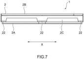
- FIG. 7 is a side view of the pressure-regulating valve 1 for a power storage module
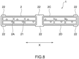
- Fig. 8 is a bottom view of the pressure-regulating valve 1 for a power storage module
- Fig. 9 is a sectional view showing an essential part of the pressure-regulating valve 1 for a power storage module.
- the pressure-regulating valve 1 for a power storage module is a pressure-regulating valve for a power storage module in which a case 2 accommodating a valve body in a valve chamber is to be attached to a power storage device 10, and the case 2 has a sealing surface 2A that is provided with a sealing member 21 and is to contact the power storage device 10, and an attaching portion 22 capable of being attached to the power storage device 10 by moving along a predetermined slide direction (X direction) along the sealing surface 2A.
- the power storage unit 100 includes the pressure-regulating valve 1 for a power storage module and the power storage device (power storage module) 10.
- the pressure-regulating valve 1 for a power storage module and the power storage unit 100 will be specifically described.
- the pressure-regulating valve 1 for a power storage module is configured to release pressure when internal pressure rises in the power storage device 10.
- the power storage device 10 is, for example, a nickel hydrogen battery, and is provided to supply electric power to a motor in a vehicle such as an electric car, and a hybrid car.
- the case 2 is entirely formed of, for example, a synthetic resin into a rectangular parallelepiped shape, and has the sealing surface 2A facing a power storage device 10 side, and an open surface 2B facing an opposite side thereto.
- a plurality of recessed parts are formed seen from the open surface 2B, and the recessed part forms the valve chamber, where the valve body which is an elastic member is accommodated.
- a through-hole is formed in a bottom portion of each of the recessed parts, and gas can be introduced into the recessed part from a sealing surface 2A side.
- a cover member is provided on an open surface 2B side of the case 2, and the recessed parts are closed.
- the cover member is preferably attachable and detachable with respect to the case 2.
- the cover member may be provided with a pressing portion that presses the valve body to a valve closing side.
- the sealing surface 2A of the case 2 is formed into a frame shape as shown in Figs 4 and 5 .
- a region in each of frames corresponds to an opening portion on the power storage device 10 side, and an appropriate number of recessed parts are formed in the region in each of the frames.
- a sealing member 21 which is an elastic member is provided along the frame.
- the sealing member 21 can be an elastic member such as a rubber and a resin, for example, and can be provided at the case 2 by integral molding, for example.
- an extending direction (direction of a longest side) of the case 2 in the rectangular parallelepiped shape is defined as an X direction.
- the X direction is the slide direction.
- the case 2 has a pair of side surfaces 2C and 2D that are sandwiched by the sealing surface 2A and the open surface 2B and along the X direction.
- the side surfaces 2C and 2D are a pair of edge portions along the slide direction.
- Three attaching portions 22 are formed at each of portions on a sealing surface 2A side, of the side surfaces 2C and 2D.
- the attaching portions 22 are formed into a plate shape protruding to outside from the side surfaces 2C and 2D.
- protruding to outside means that the attaching portion 22 formed at the side surface 2C and the attaching portion 22 formed at the side surface 2D extend to be away from each other.
- the attaching portions 22 disposed in a center portion in the X direction have a dimension in the X direction larger than other attaching portions 22. Thereby, the attaching portions 22 in the center portion are engageable with only clamping portions 122 in a center of clamping portions 121 to 123 described later. Note that dimensions of all the attaching portions may differ from one another, or dimensions of each of the attaching portions in the center may be smaller than those of the other attaching portions.
- the power storage device 10 includes a casing 11 to accommodate a module having a power storing function.
- a casing 11 to accommodate a module having a power storing function.
- opening portions for releasing gas when internal pressure rises are formed, and the pressure-regulating valve 1 for a power storage module is provided to correspond to the opening portions.
- gas is released from the opening portions of the casing 11, and the gas passes through the through-holes of the case 2 and is introduced into the recessed part.
- pressure in the recessed part reaches a value equal to or larger than a preset value, the valve body opens the through-hole, and gas is released to an external space.
- the casing 11 of the power storage device 10 is provided with a holding portion 12 for attaching the case 2 of the pressure-regulating valve 1 for a power storage module by holding the attaching portions 22.
- the holding portion 12 is formed to protrude from an attaching surface 11A in which the opening portions are formed, of the casing 11.
- the holding portion 12 is configured by three pairs of clamping portions 121 to 123 correspondingly to the attaching portions 22 of the case 2. Note that the numbers of the attaching portions 22 and the clamping portions 121 to 123 are not limited to the numbers described above.
- the attaching surface 11A is a surface which the sealing surface 2A of the case 2 contacts.
- Each of the clamping portions 121 to 123 is positioned along the attaching surface 11A (along the sealing surface 2A) to clamp the case 2 from a direction orthogonal to the X direction.
- the sealing surface 2A of the case 2 is brought into contact with the attaching surface 11A of the casing 11, and the case 2 is brought into a state of being clamped by the clamping portions 121 and 122. From this state, the case 2 is slid and moved along the X direction with respect to the casing 11 as shown in Fig. 3 . Thereby, the respective attaching portions 22 move to positions corresponding to the clamping portions 121 to 123 and are locked. It is preferable that at a time of such locking, the sealing member 21 is compressed and thereby closely contacts the attaching surface 11A.
- the clamping portions 121 to 123 each have a recessed part 120.
- the attaching portion 22 is locked to the recessed part 120 by getting over wall parts adjacent in the X direction, and fitting in the recessed part 120 by the slide movement as described above. In this way, the attaching portion 22 functions as a locked portion.
- a locking structure of the holding portion 12 and the attaching portion 22 is not limited to the above-described structure but may be any structure if the attaching portions 22 are locked by slide movement in the X direction. Further, a tapered portion or the like may be formed on the attaching portion so that the attaching portion may easily get over the wall parts at the time of locking.
- the opening portions of the casing 11 correspond to the region in the frame of the sealing surface 2A, gas can be introduced into the recessed parts from the casing 11, and the pressure-regulating valve 1 for a power storage module can function.
- the pressure-regulating valve 1 for a power storage module according to the embodiment of the present invention, as a result of the case 2 having the attaching portions 22, the pressure-regulating valve 1 for a power storage module and the power storage device 10 become attachable and detachable by being relatively moved along the slide direction, and it is possible to improve maintainability.
- the attaching portions 22 protrude from the side surfaces 2C and 2D of the case 2, it is possible to easily lock the attaching portions 22 by the power storage device 10.
- the holding portion 12 is configured by the plurality of pairs of clamping portions 121 to 123 that clamp the case 2, it is possible to guide the case 2 along the X direction, and improve workability of attachment and detachment. Furthermore, it is possible to slide and move the case 2 after the case 2 is positioned so that the attaching portions 22 are each located between the two pairs of clamping portions that are lined up in the X direction, and it is possible to decrease a slide amount at the time of attaching and detaching, and improve workability, as compared with the case in which the holding portion is configured by only one pair of clamping portions.
- the present invention is not limited to the above-described embodiment but includes other configurations and the like that can achieve the object of the present invention, and modifications and the like as shown below are also included in the present invention.
- the attaching portions 22 protrude from the side surfaces 2C and 2D of the case 2, but the attaching portions may be formed into a protrusion shape protruding from the sealing surface, and recessed parts and through-holes that receive the protrusions may be formed on the attaching surface of the power storage device.
- the holding portion 12 is configured by the plurality of clamping portions 121 to 123 that clamp the case 2, but the holding portion may be configured by only one pair of clamping portions.
- the present invention is not limited to the pressure-regulating valve for a power storage module according to the embodiment of the present invention described above, but includes all aspects included in the idea and the claims of the present invention. Further, in order to exhibit at least a part of the problem and the effects described above, the respective configurations may be selectively combined as appropriate. For example, the shapes, materials, placements, sizes and the like of the respective components in the above-described embodiment can be changed as appropriate according to a specific use aspect of the present invention.
Landscapes
- Chemical & Material Sciences (AREA)
- Chemical Kinetics & Catalysis (AREA)
- Electrochemistry (AREA)
- General Chemical & Material Sciences (AREA)
- Gas Exhaust Devices For Batteries (AREA)
- Battery Mounting, Suspending (AREA)
Abstract
Description
- The present invention relates to a pressure-regulating valve for a power storage module and a power storage unit.
- Conventionally, as a power storage module for a battery to be mounted on a vehicle, there has been proposed a power storage module provided with a pressure-regulating valve (for example, see Patent Literature 1). In the power storage module described in
Patent Literature 1, the pressure-regulating valve includes a base member, a case member in which a cylindrical portion is formed, a valve body that is an elastic member to be accommodated in the cylindrical portion, and a cover member that closes an opening of the case member. The base member is welded to a frame body of the power storage module, and the case member is welded to the base member, whereby the pressure-regulating valve is fixed. - Patent Literature 1: International Publication No.
WO 2019/064843 - However, in the power storage module described in
Patent Literature 1, if deterioration, abnormality or the like occurs in the valve body or the like as a result of using the pressure-regulating valve, it has been impossible to remove the pressure-regulating valve because the case member is welded to the base member, and it has been impossible to perform replacement and inspection of the components. Thus, it has been desired to improve maintainability of the pressure-regulating valve. - The present invention is made in view of the aforementioned problem, and it is an object of the present invention to provide a pressure-regulating valve for a power storage module capable of improving maintenance, and a power storage unit including the pressure-regulating valve for a power storage module.
- In order to attain the above-described object, a pressure-regulating valve for a power storage module according to the present invention is a pressure-regulating valve for a power storage module in which a case accommodating a valve body in a valve chamber is to be attached to a power storage device, wherein the case has a sealing surface that is provided with a sealing member and is to contact the power storage device, and an attaching portion attachable to the power storage device by moving along a predetermined slide direction along the sealing surface.
- In the pressure-regulating valve for a power storage module according to one aspect of the present invention, the case has a pair of edge portions along the slide direction, and the attaching portion is a locked portion that is locked by the power storage device by protruding to outside from each of the edge portions.
- A power storage unit according to the present invention is a power storage unit including the above-described pressure-regulating valve for a power storage module, and a power storage device, wherein the power storage device has a holding portion to hold the attaching portion.
- In the power storage unit according to one aspect of the present invention, the holding portion has a plurality of pairs of clamping portions to clamp the case from a direction along the sealing surface and orthogonal to the slide direction.
- According to the pressure-regulating valve for a power storage module according to the present invention, it is possible to improve maintainability.
-
- [
Fig. 1] Fig. 1 is a perspective view of a power storage unit including a pressure-regulating valve for a power storage module according to an embodiment of the present invention. - [
Fig. 2] Fig. 2 is a perspective view of the pressure-regulating valve for a power storage module according to the embodiment of the present invention. - [
Fig. 3] Fig. 3 is a perspective view of the pressure-regulating valve for a power storage module according to the embodiment of the present invention. - [
Fig. 4] Fig. 4 is a perspective view of the pressure-regulating valve for a power storage module according to the embodiment of the present invention. - [
Fig. 5] Fig. 5 is a perspective view of the pressure-regulating valve for a power storage module according to the embodiment of the present invention. - [
Fig. 6] Fig. 6 is a plan view of the pressure-regulating valve for a power storage module according to the embodiment of the present invention. - [
Fig. 7] Fig. 7 is a side view of the pressure-regulating valve for a power storage module according to the embodiment of the present invention. - [
Fig. 8] Fig. 8 is a bottom view of the pressure-regulating valve for a power storage module according to the embodiment of the present invention. - [
Fig. 9] Fig. 9 is a sectional view showing an essential part of the pressure-regulating valve for a power storage module according to the embodiment of the present invention. - Hereinafter, an embodiment of the present invention will be described with reference to the drawings.
Fig. 1 is a perspective view of apower storage unit 100 including a pressure-regulatingvalve 1 for a power storage module according to the embodiment of the present invention,Fig. 2 is a perspective view of the pressure-regulatingvalve 1 for a power storage module,Fig. 3 is a perspective view of the pressure-regulatingvalve 1 for a power storage module,Fig. 4 is a perspective view of the pressure-regulatingvalve 1 for a power storage module,Fig. 5 is a perspective view of the pressure-regulatingvalve 1 for a power storage module,Fig. 6 is a plan view of the pressure-regulatingvalve 1 for a power storage module,Fig. 7 is a side view of the pressure-regulatingvalve 1 for a power storage module,Fig. 8 is a bottom view of the pressure-regulatingvalve 1 for a power storage module, andFig. 9 is a sectional view showing an essential part of the pressure-regulatingvalve 1 for a power storage module. - As shown in
Figs. 1 to 8 , the pressure-regulatingvalve 1 for a power storage module according to the embodiment of the present invention is a pressure-regulating valve for a power storage module in which acase 2 accommodating a valve body in a valve chamber is to be attached to apower storage device 10, and thecase 2 has asealing surface 2A that is provided with asealing member 21 and is to contact thepower storage device 10, and an attachingportion 22 capable of being attached to thepower storage device 10 by moving along a predetermined slide direction (X direction) along the sealingsurface 2A. Thepower storage unit 100 includes the pressure-regulatingvalve 1 for a power storage module and the power storage device (power storage module) 10. Hereinafter, the pressure-regulatingvalve 1 for a power storage module and thepower storage unit 100 will be specifically described. - The pressure-regulating
valve 1 for a power storage module is configured to release pressure when internal pressure rises in thepower storage device 10. Thepower storage device 10 is, for example, a nickel hydrogen battery, and is provided to supply electric power to a motor in a vehicle such as an electric car, and a hybrid car. - The
case 2 is entirely formed of, for example, a synthetic resin into a rectangular parallelepiped shape, and has the sealingsurface 2A facing apower storage device 10 side, and anopen surface 2B facing an opposite side thereto. In thecase 2, a plurality of recessed parts are formed seen from theopen surface 2B, and the recessed part forms the valve chamber, where the valve body which is an elastic member is accommodated. A through-hole is formed in a bottom portion of each of the recessed parts, and gas can be introduced into the recessed part from a sealingsurface 2A side. - A cover member is provided on an
open surface 2B side of thecase 2, and the recessed parts are closed. In this case, the cover member is preferably attachable and detachable with respect to thecase 2. Further, the cover member may be provided with a pressing portion that presses the valve body to a valve closing side. - The sealing
surface 2A of thecase 2 is formed into a frame shape as shown inFigs 4 and5 . A region in each of frames corresponds to an opening portion on thepower storage device 10 side, and an appropriate number of recessed parts are formed in the region in each of the frames. On the sealingsurface 2A, a sealingmember 21 which is an elastic member is provided along the frame. The sealingmember 21 can be an elastic member such as a rubber and a resin, for example, and can be provided at thecase 2 by integral molding, for example. - Here, an extending direction (direction of a longest side) of the
case 2 in the rectangular parallelepiped shape is defined as an X direction. As described later, the X direction is the slide direction. Thecase 2 has a pair ofside surfaces surface 2A and theopen surface 2B and along the X direction. In other words, theside surfaces portions 22 are formed at each of portions on a sealingsurface 2A side, of theside surfaces - The attaching
portions 22 are formed into a plate shape protruding to outside from theside surfaces portion 22 formed at theside surface 2C and the attachingportion 22 formed at theside surface 2D extend to be away from each other. The attachingportions 22 disposed in a center portion in the X direction have a dimension in the X direction larger than other attachingportions 22. Thereby, the attachingportions 22 in the center portion are engageable with only clampingportions 122 in a center of clampingportions 121 to 123 described later. Note that dimensions of all the attaching portions may differ from one another, or dimensions of each of the attaching portions in the center may be smaller than those of the other attaching portions. - The
power storage device 10 includes acasing 11 to accommodate a module having a power storing function. In thecasing 11, opening portions for releasing gas when internal pressure rises are formed, and the pressure-regulatingvalve 1 for a power storage module is provided to correspond to the opening portions. In other words, when the internal pressure of thepower storage device 10 rises, gas is released from the opening portions of thecasing 11, and the gas passes through the through-holes of thecase 2 and is introduced into the recessed part. When pressure in the recessed part reaches a value equal to or larger than a preset value, the valve body opens the through-hole, and gas is released to an external space. - The
casing 11 of thepower storage device 10 is provided with aholding portion 12 for attaching thecase 2 of the pressure-regulatingvalve 1 for a power storage module by holding the attachingportions 22. Theholding portion 12 is formed to protrude from an attachingsurface 11A in which the opening portions are formed, of thecasing 11. Theholding portion 12 is configured by three pairs of clampingportions 121 to 123 correspondingly to the attachingportions 22 of thecase 2. Note that the numbers of the attachingportions 22 and the clampingportions 121 to 123 are not limited to the numbers described above. The attachingsurface 11A is a surface which thesealing surface 2A of thecase 2 contacts. Each of the clampingportions 121 to 123 is positioned along the attachingsurface 11A (along the sealingsurface 2A) to clamp thecase 2 from a direction orthogonal to the X direction. - Here, details of an attaching method and an attaching structure of the
case 2 to thecasing 11 are described. First, as shown inFig. 2 , the sealingsurface 2A of thecase 2 is brought into contact with the attachingsurface 11A of thecasing 11, and thecase 2 is brought into a state of being clamped by the clampingportions case 2 is slid and moved along the X direction with respect to thecasing 11 as shown inFig. 3 . Thereby, the respective attachingportions 22 move to positions corresponding to the clampingportions 121 to 123 and are locked. It is preferable that at a time of such locking, the sealingmember 21 is compressed and thereby closely contacts the attachingsurface 11A. - As shown in
Fig. 9 , the clampingportions 121 to 123 each have a recessedpart 120. The attachingportion 22 is locked to the recessedpart 120 by getting over wall parts adjacent in the X direction, and fitting in the recessedpart 120 by the slide movement as described above. In this way, the attachingportion 22 functions as a locked portion. Note that a locking structure of the holdingportion 12 and the attachingportion 22 is not limited to the above-described structure but may be any structure if the attachingportions 22 are locked by slide movement in the X direction. Further, a tapered portion or the like may be formed on the attaching portion so that the attaching portion may easily get over the wall parts at the time of locking. - In the state in which the attaching
portion 22 is locked by the holdingportion 12 as described above, the opening portions of thecasing 11 correspond to the region in the frame of the sealingsurface 2A, gas can be introduced into the recessed parts from thecasing 11, and the pressure-regulatingvalve 1 for a power storage module can function. - As a result of the pressure-regulating
valve 1 for a power storage module repeating opening and closing by using thepower storage unit 100, and the valve body deteriorating over time, desired valve opening characteristics may not be obtained. In such a case, from the state in which the attachingportions 22 are locked by the holdingportion 12 as inFig. 3 , thecase 2 is slid and moved along the X direction with respect to thecasing 11 and brought into a state in which locking is released as inFig. 2 . Thereby, it is possible to remove the pressure-regulatingvalve 1 for a power storage module from thepower storage device 10, and appropriate maintenance work such as replacement and inspection of components becomes possible. Further, it is also possible to replace the entire pressure-regulatingvalve 1 for a power storage module. - When the
case 2 is slid and moved along the X direction at a time of attaching and detaching as described above, a configuration in which a moving direction at the time of attaching and a moving direction at a time of releasing attachment are determined (being locked by moving to one side of the X direction, and locking is released by moving to another side) may be adopted, or both attaching and detaching may be possible when the case is moved in either direction. - In this way, according to the pressure-regulating
valve 1 for a power storage module according to the embodiment of the present invention, as a result of thecase 2 having the attachingportions 22, the pressure-regulatingvalve 1 for a power storage module and thepower storage device 10 become attachable and detachable by being relatively moved along the slide direction, and it is possible to improve maintainability. - Further, since the attaching
portions 22 protrude from the side surfaces 2C and 2D of thecase 2, it is possible to easily lock the attachingportions 22 by thepower storage device 10. - Further, since the holding
portion 12 is configured by the plurality of pairs of clampingportions 121 to 123 that clamp thecase 2, it is possible to guide thecase 2 along the X direction, and improve workability of attachment and detachment. Furthermore, it is possible to slide and move thecase 2 after thecase 2 is positioned so that the attachingportions 22 are each located between the two pairs of clamping portions that are lined up in the X direction, and it is possible to decrease a slide amount at the time of attaching and detaching, and improve workability, as compared with the case in which the holding portion is configured by only one pair of clamping portions. - Note that the present invention is not limited to the above-described embodiment but includes other configurations and the like that can achieve the object of the present invention, and modifications and the like as shown below are also included in the present invention. For example, in the embodiment of the present invention described above, the attaching
portions 22 protrude from the side surfaces 2C and 2D of thecase 2, but the attaching portions may be formed into a protrusion shape protruding from the sealing surface, and recessed parts and through-holes that receive the protrusions may be formed on the attaching surface of the power storage device. - Further, in the embodiment of the present invention described above, the holding
portion 12 is configured by the plurality of clampingportions 121 to 123 that clamp thecase 2, but the holding portion may be configured by only one pair of clamping portions. - Although the embodiment of the present invention is described thus far, the present invention is not limited to the pressure-regulating valve for a power storage module according to the embodiment of the present invention described above, but includes all aspects included in the idea and the claims of the present invention. Further, in order to exhibit at least a part of the problem and the effects described above, the respective configurations may be selectively combined as appropriate. For example, the shapes, materials, placements, sizes and the like of the respective components in the above-described embodiment can be changed as appropriate according to a specific use aspect of the present invention.
- List of Reference Signs
-
- 1 pressure-regulating valve for power storage module
- 2 case
- 21 sealing member
- 22 attaching portion
- 2A sealing surface
- 2B open surface
- 2C, 2D side surface (edge portion)
- 10 power storage device (power storage module)
- 11 casing
- 11A attaching surface
- 12 holding portion
- 121 to 123 clamping portion
- 120 recessed part
- 100 power storage unit
Claims (4)
- A pressure-regulating valve for a power storage module in which a case accommodating a valve body in a valve chamber is to be attached to a power storage device, wherein
the case has a sealing surface that is provided with a sealing member and is to contact the power storage device, and an attaching portion attachable to the power storage device by moving along a predetermined slide direction along the sealing surface. - The pressure-regulating valve for a power storage module according to claim 1, whereinthe case has a pair of edge portions along the slide direction, andthe attaching portion is a locked portion that is locked by the power storage device by protruding to outside from each of the edge portions.
- A power storage unit comprising a pressure-regulating valve for a power storage module according to claim 1 or 2, and a power storage device,
wherein the power storage device has a holding portion to hold the attaching portion. - The power storage unit according to claim 3, wherein the holding portion has a plurality of pairs of clamping portions to clamp the case from a direction along the sealing surface and orthogonal to the slide direction.
Applications Claiming Priority (2)
| Application Number | Priority Date | Filing Date | Title |
|---|---|---|---|
| JP2021151486 | 2021-09-16 | ||
| PCT/JP2022/029893 WO2023042569A1 (en) | 2021-09-16 | 2022-08-04 | Pressure regulating valve for power storage module, and power storage unit |
Publications (2)
| Publication Number | Publication Date |
|---|---|
| EP4404358A1 true EP4404358A1 (en) | 2024-07-24 |
| EP4404358A4 EP4404358A4 (en) | 2025-08-13 |
Family
ID=85602737
Family Applications (1)
| Application Number | Title | Priority Date | Filing Date |
|---|---|---|---|
| EP22869717.3A Pending EP4404358A4 (en) | 2021-09-16 | 2022-08-04 | PRESSURE CONTROL VALVE FOR ENERGY STORAGE MODULE AND ENERGY STORAGE UNIT |
Country Status (6)
| Country | Link |
|---|---|
| US (1) | US20250132448A1 (en) |
| EP (1) | EP4404358A4 (en) |
| JP (1) | JP7503717B2 (en) |
| KR (1) | KR102887644B1 (en) |
| CN (1) | CN117941147A (en) |
| WO (1) | WO2023042569A1 (en) |
Family Cites Families (7)
| Publication number | Priority date | Publication date | Assignee | Title |
|---|---|---|---|---|
| JP4613728B2 (en) * | 2005-07-26 | 2011-01-19 | パナソニック株式会社 | Capacitor |
| US10637025B2 (en) | 2011-08-01 | 2020-04-28 | Doyle Manufacturing, Inc. | Battery vent cap |
| JP5974520B2 (en) | 2012-02-08 | 2016-08-23 | 株式会社Gsユアサ | Power storage device and power storage module |
| JP2019061850A (en) * | 2017-09-26 | 2019-04-18 | 株式会社豊田自動織機 | Power storge module and method for manufacturing the same |
| CN111164793B (en) * | 2017-09-26 | 2022-08-05 | 株式会社丰田自动织机 | Electricity storage module |
| US11355785B2 (en) | 2017-09-26 | 2022-06-07 | Kabushiki Kaisha Toyota Jidoshokki | Power storage module and method for manufacturing power storage module |
| JP7107819B2 (en) * | 2018-11-08 | 2022-07-27 | 株式会社豊田自動織機 | power storage device |
-
2022
- 2022-08-04 JP JP2023548159A patent/JP7503717B2/en active Active
- 2022-08-04 EP EP22869717.3A patent/EP4404358A4/en active Pending
- 2022-08-04 US US18/689,701 patent/US20250132448A1/en active Pending
- 2022-08-04 WO PCT/JP2022/029893 patent/WO2023042569A1/en not_active Ceased
- 2022-08-04 KR KR1020247007642A patent/KR102887644B1/en active Active
- 2022-08-04 CN CN202280062731.1A patent/CN117941147A/en active Pending
Also Published As
| Publication number | Publication date |
|---|---|
| JPWO2023042569A1 (en) | 2023-03-23 |
| KR20240036135A (en) | 2024-03-19 |
| KR102887644B1 (en) | 2025-11-21 |
| EP4404358A4 (en) | 2025-08-13 |
| JP7503717B2 (en) | 2024-06-20 |
| CN117941147A (en) | 2024-04-26 |
| US20250132448A1 (en) | 2025-04-24 |
| WO2023042569A1 (en) | 2023-03-23 |
Similar Documents
| Publication | Publication Date | Title |
|---|---|---|
| US20110100704A1 (en) | Sealing cover for electric equipment mounted on car | |
| US10003054B2 (en) | Power source pack | |
| US20220294093A1 (en) | End cover assembly, secondary battery, battery module, appratus, liquid-injection method and device | |
| JP5835098B2 (en) | Assembled battery | |
| JP6922704B2 (en) | How to manufacture assembled batteries | |
| KR101393436B1 (en) | Battery module and cell-cartridge | |
| US20170279094A1 (en) | Power storage module | |
| JP2009164085A (en) | Battery module | |
| US8293400B2 (en) | Battery including opening closure member with case contact part and case inside part | |
| KR101435678B1 (en) | Battery charging device and battery with the same | |
| US20160093855A1 (en) | Energy storage apparatus | |
| KR20220042840A (en) | Battery pack and vehicle comprising the battery pack | |
| US20250132448A1 (en) | Pressure-regulating valve for power storage module and power storage unit | |
| WO2024142476A1 (en) | Battery pack | |
| JP7445188B2 (en) | battery module | |
| KR20170047084A (en) | Battery Protecting Structure And Battery Module Comprising The Same | |
| KR20220054208A (en) | Battery connection device | |
| CN221245251U (en) | Container sealing device and container sealing equipment | |
| CN117916937A (en) | Pressure regulating valve for battery module | |
| JP2011000913A (en) | Mounting structure for energy storage | |
| CN110474003B (en) | Battery box | |
| CN209800831U (en) | Tap waterway control box | |
| EP4404364A1 (en) | Pressure-regulating valve for power storage module | |
| JP7406243B2 (en) | Terminal block | |
| JP2018067481A (en) | Battery pack |
Legal Events
| Date | Code | Title | Description |
|---|---|---|---|
| STAA | Information on the status of an ep patent application or granted ep patent |
Free format text: STATUS: THE INTERNATIONAL PUBLICATION HAS BEEN MADE |
|
| PUAI | Public reference made under article 153(3) epc to a published international application that has entered the european phase |
Free format text: ORIGINAL CODE: 0009012 |
|
| STAA | Information on the status of an ep patent application or granted ep patent |
Free format text: STATUS: REQUEST FOR EXAMINATION WAS MADE |
|
| 17P | Request for examination filed |
Effective date: 20240315 |
|
| AK | Designated contracting states |
Kind code of ref document: A1 Designated state(s): AL AT BE BG CH CY CZ DE DK EE ES FI FR GB GR HR HU IE IS IT LI LT LU LV MC MK MT NL NO PL PT RO RS SE SI SK SM TR |
|
| DAV | Request for validation of the european patent (deleted) | ||
| DAX | Request for extension of the european patent (deleted) | ||
| A4 | Supplementary search report drawn up and despatched |
Effective date: 20250711 |
|
| RIC1 | Information provided on ipc code assigned before grant |
Ipc: H01M 50/308 20210101AFI20250707BHEP Ipc: H01M 50/317 20210101ALI20250707BHEP Ipc: H01M 50/325 20210101ALI20250707BHEP Ipc: H01M 50/358 20210101ALI20250707BHEP |