EP4404354A1 - Battery and electric device - Google Patents
Battery and electric device Download PDFInfo
- Publication number
- EP4404354A1 EP4404354A1 EP22948218.7A EP22948218A EP4404354A1 EP 4404354 A1 EP4404354 A1 EP 4404354A1 EP 22948218 A EP22948218 A EP 22948218A EP 4404354 A1 EP4404354 A1 EP 4404354A1
- Authority
- EP
- European Patent Office
- Prior art keywords
- battery
- support plate
- box body
- battery cells
- present application
- Prior art date
- Legal status (The legal status is an assumption and is not a legal conclusion. Google has not performed a legal analysis and makes no representation as to the accuracy of the status listed.)
- Pending
Links
Images




Classifications
-
- H—ELECTRICITY
- H01—ELECTRIC ELEMENTS
- H01M—PROCESSES OR MEANS, e.g. BATTERIES, FOR THE DIRECT CONVERSION OF CHEMICAL ENERGY INTO ELECTRICAL ENERGY
- H01M50/00—Constructional details or processes of manufacture of the non-active parts of electrochemical cells other than fuel cells, e.g. hybrid cells
- H01M50/20—Mountings; Secondary casings or frames; Racks, modules or packs; Suspension devices; Shock absorbers; Transport or carrying devices; Holders
- H01M50/258—Modular batteries; Casings provided with means for assembling
-
- H—ELECTRICITY
- H01—ELECTRIC ELEMENTS
- H01M—PROCESSES OR MEANS, e.g. BATTERIES, FOR THE DIRECT CONVERSION OF CHEMICAL ENERGY INTO ELECTRICAL ENERGY
- H01M50/00—Constructional details or processes of manufacture of the non-active parts of electrochemical cells other than fuel cells, e.g. hybrid cells
- H01M50/20—Mountings; Secondary casings or frames; Racks, modules or packs; Suspension devices; Shock absorbers; Transport or carrying devices; Holders
- H01M50/289—Mountings; Secondary casings or frames; Racks, modules or packs; Suspension devices; Shock absorbers; Transport or carrying devices; Holders characterised by spacing elements or positioning means within frames, racks or packs
- H01M50/291—Mountings; Secondary casings or frames; Racks, modules or packs; Suspension devices; Shock absorbers; Transport or carrying devices; Holders characterised by spacing elements or positioning means within frames, racks or packs characterised by their shape
-
- H—ELECTRICITY
- H01—ELECTRIC ELEMENTS
- H01M—PROCESSES OR MEANS, e.g. BATTERIES, FOR THE DIRECT CONVERSION OF CHEMICAL ENERGY INTO ELECTRICAL ENERGY
- H01M10/00—Secondary cells; Manufacture thereof
- H01M10/04—Construction or manufacture in general
-
- H—ELECTRICITY
- H01—ELECTRIC ELEMENTS
- H01M—PROCESSES OR MEANS, e.g. BATTERIES, FOR THE DIRECT CONVERSION OF CHEMICAL ENERGY INTO ELECTRICAL ENERGY
- H01M50/00—Constructional details or processes of manufacture of the non-active parts of electrochemical cells other than fuel cells, e.g. hybrid cells
- H01M50/10—Primary casings; Jackets or wrappings
- H01M50/102—Primary casings; Jackets or wrappings characterised by their shape or physical structure
- H01M50/103—Primary casings; Jackets or wrappings characterised by their shape or physical structure prismatic or rectangular
-
- H—ELECTRICITY
- H01—ELECTRIC ELEMENTS
- H01M—PROCESSES OR MEANS, e.g. BATTERIES, FOR THE DIRECT CONVERSION OF CHEMICAL ENERGY INTO ELECTRICAL ENERGY
- H01M50/00—Constructional details or processes of manufacture of the non-active parts of electrochemical cells other than fuel cells, e.g. hybrid cells
- H01M50/10—Primary casings; Jackets or wrappings
- H01M50/147—Lids or covers
- H01M50/148—Lids or covers characterised by their shape
- H01M50/15—Lids or covers characterised by their shape for prismatic or rectangular cells
-
- H—ELECTRICITY
- H01—ELECTRIC ELEMENTS
- H01M—PROCESSES OR MEANS, e.g. BATTERIES, FOR THE DIRECT CONVERSION OF CHEMICAL ENERGY INTO ELECTRICAL ENERGY
- H01M50/00—Constructional details or processes of manufacture of the non-active parts of electrochemical cells other than fuel cells, e.g. hybrid cells
- H01M50/20—Mountings; Secondary casings or frames; Racks, modules or packs; Suspension devices; Shock absorbers; Transport or carrying devices; Holders
- H01M50/204—Racks, modules or packs for multiple batteries or multiple cells
- H01M50/207—Racks, modules or packs for multiple batteries or multiple cells characterised by their shape
- H01M50/209—Racks, modules or packs for multiple batteries or multiple cells characterised by their shape adapted for prismatic or rectangular cells
-
- H—ELECTRICITY
- H01—ELECTRIC ELEMENTS
- H01M—PROCESSES OR MEANS, e.g. BATTERIES, FOR THE DIRECT CONVERSION OF CHEMICAL ENERGY INTO ELECTRICAL ENERGY
- H01M50/00—Constructional details or processes of manufacture of the non-active parts of electrochemical cells other than fuel cells, e.g. hybrid cells
- H01M50/20—Mountings; Secondary casings or frames; Racks, modules or packs; Suspension devices; Shock absorbers; Transport or carrying devices; Holders
- H01M50/233—Mountings; Secondary casings or frames; Racks, modules or packs; Suspension devices; Shock absorbers; Transport or carrying devices; Holders characterised by physical properties of casings or racks, e.g. dimensions
- H01M50/242—Mountings; Secondary casings or frames; Racks, modules or packs; Suspension devices; Shock absorbers; Transport or carrying devices; Holders characterised by physical properties of casings or racks, e.g. dimensions adapted for protecting batteries against vibrations, collision impact or swelling
-
- H—ELECTRICITY
- H01—ELECTRIC ELEMENTS
- H01M—PROCESSES OR MEANS, e.g. BATTERIES, FOR THE DIRECT CONVERSION OF CHEMICAL ENERGY INTO ELECTRICAL ENERGY
- H01M50/00—Constructional details or processes of manufacture of the non-active parts of electrochemical cells other than fuel cells, e.g. hybrid cells
- H01M50/20—Mountings; Secondary casings or frames; Racks, modules or packs; Suspension devices; Shock absorbers; Transport or carrying devices; Holders
- H01M50/244—Secondary casings; Racks; Suspension devices; Carrying devices; Holders characterised by their mounting method
-
- H—ELECTRICITY
- H01—ELECTRIC ELEMENTS
- H01M—PROCESSES OR MEANS, e.g. BATTERIES, FOR THE DIRECT CONVERSION OF CHEMICAL ENERGY INTO ELECTRICAL ENERGY
- H01M50/00—Constructional details or processes of manufacture of the non-active parts of electrochemical cells other than fuel cells, e.g. hybrid cells
- H01M50/20—Mountings; Secondary casings or frames; Racks, modules or packs; Suspension devices; Shock absorbers; Transport or carrying devices; Holders
- H01M50/249—Mountings; Secondary casings or frames; Racks, modules or packs; Suspension devices; Shock absorbers; Transport or carrying devices; Holders specially adapted for aircraft or vehicles, e.g. cars or trains
-
- H—ELECTRICITY
- H01—ELECTRIC ELEMENTS
- H01M—PROCESSES OR MEANS, e.g. BATTERIES, FOR THE DIRECT CONVERSION OF CHEMICAL ENERGY INTO ELECTRICAL ENERGY
- H01M50/00—Constructional details or processes of manufacture of the non-active parts of electrochemical cells other than fuel cells, e.g. hybrid cells
- H01M50/20—Mountings; Secondary casings or frames; Racks, modules or packs; Suspension devices; Shock absorbers; Transport or carrying devices; Holders
- H01M50/262—Mountings; Secondary casings or frames; Racks, modules or packs; Suspension devices; Shock absorbers; Transport or carrying devices; Holders with fastening means, e.g. locks
- H01M50/264—Mountings; Secondary casings or frames; Racks, modules or packs; Suspension devices; Shock absorbers; Transport or carrying devices; Holders with fastening means, e.g. locks for cells or batteries, e.g. straps, tie rods or peripheral frames
-
- H—ELECTRICITY
- H01—ELECTRIC ELEMENTS
- H01M—PROCESSES OR MEANS, e.g. BATTERIES, FOR THE DIRECT CONVERSION OF CHEMICAL ENERGY INTO ELECTRICAL ENERGY
- H01M50/00—Constructional details or processes of manufacture of the non-active parts of electrochemical cells other than fuel cells, e.g. hybrid cells
- H01M50/20—Mountings; Secondary casings or frames; Racks, modules or packs; Suspension devices; Shock absorbers; Transport or carrying devices; Holders
- H01M50/271—Lids or covers for the racks or secondary casings
-
- H—ELECTRICITY
- H01—ELECTRIC ELEMENTS
- H01M—PROCESSES OR MEANS, e.g. BATTERIES, FOR THE DIRECT CONVERSION OF CHEMICAL ENERGY INTO ELECTRICAL ENERGY
- H01M50/00—Constructional details or processes of manufacture of the non-active parts of electrochemical cells other than fuel cells, e.g. hybrid cells
- H01M50/30—Arrangements for facilitating escape of gases
-
- H—ELECTRICITY
- H01—ELECTRIC ELEMENTS
- H01M—PROCESSES OR MEANS, e.g. BATTERIES, FOR THE DIRECT CONVERSION OF CHEMICAL ENERGY INTO ELECTRICAL ENERGY
- H01M50/00—Constructional details or processes of manufacture of the non-active parts of electrochemical cells other than fuel cells, e.g. hybrid cells
- H01M50/50—Current conducting connections for cells or batteries
- H01M50/543—Terminals
- H01M50/547—Terminals characterised by the disposition of the terminals on the cells
- H01M50/55—Terminals characterised by the disposition of the terminals on the cells on the same side of the cell
-
- B—PERFORMING OPERATIONS; TRANSPORTING
- B60—VEHICLES IN GENERAL
- B60R—VEHICLES, VEHICLE FITTINGS, OR VEHICLE PARTS, NOT OTHERWISE PROVIDED FOR
- B60R16/00—Electric or fluid circuits specially adapted for vehicles and not otherwise provided for; Arrangement of elements of electric or fluid circuits specially adapted for vehicles and not otherwise provided for
- B60R16/02—Electric or fluid circuits specially adapted for vehicles and not otherwise provided for; Arrangement of elements of electric or fluid circuits specially adapted for vehicles and not otherwise provided for electric constitutive elements
- B60R16/03—Electric or fluid circuits specially adapted for vehicles and not otherwise provided for; Arrangement of elements of electric or fluid circuits specially adapted for vehicles and not otherwise provided for electric constitutive elements for supply of electrical power to vehicle subsystems or for
- B60R16/033—Electric or fluid circuits specially adapted for vehicles and not otherwise provided for; Arrangement of elements of electric or fluid circuits specially adapted for vehicles and not otherwise provided for electric constitutive elements for supply of electrical power to vehicle subsystems or for characterised by the use of electrical cells or batteries
-
- H—ELECTRICITY
- H01—ELECTRIC ELEMENTS
- H01M—PROCESSES OR MEANS, e.g. BATTERIES, FOR THE DIRECT CONVERSION OF CHEMICAL ENERGY INTO ELECTRICAL ENERGY
- H01M2200/00—Safety devices for primary or secondary batteries
- H01M2200/20—Pressure-sensitive devices
-
- H—ELECTRICITY
- H01—ELECTRIC ELEMENTS
- H01M—PROCESSES OR MEANS, e.g. BATTERIES, FOR THE DIRECT CONVERSION OF CHEMICAL ENERGY INTO ELECTRICAL ENERGY
- H01M2220/00—Batteries for particular applications
- H01M2220/20—Batteries in motive systems, e.g. vehicle, ship, plane
-
- Y—GENERAL TAGGING OF NEW TECHNOLOGICAL DEVELOPMENTS; GENERAL TAGGING OF CROSS-SECTIONAL TECHNOLOGIES SPANNING OVER SEVERAL SECTIONS OF THE IPC; TECHNICAL SUBJECTS COVERED BY FORMER USPC CROSS-REFERENCE ART COLLECTIONS [XRACs] AND DIGESTS
- Y02—TECHNOLOGIES OR APPLICATIONS FOR MITIGATION OR ADAPTATION AGAINST CLIMATE CHANGE
- Y02E—REDUCTION OF GREENHOUSE GAS [GHG] EMISSIONS, RELATED TO ENERGY GENERATION, TRANSMISSION OR DISTRIBUTION
- Y02E60/00—Enabling technologies; Technologies with a potential or indirect contribution to GHG emissions mitigation
- Y02E60/10—Energy storage using batteries
Definitions
- the present application relates to the technical field of batteries, and in particular to a battery and an electrical device.
- Power batteries which are rechargeable batteries, are the power source of new energy vehicles and are widely used in the field of new energy vehicles.
- the energy density of the battery is not high, resulting in waste of space, which in turn affects the performance of the electrical apparatus.
- the existing battery has poor rigidity, cannot directly bear the load brought by other parts of the electrical apparatus, and is likely to cause safety accidents and affects the safety of the electrical apparatus.
- Embodiments of the present application provide a battery and an electrical apparatus, which can improve the energy density and the safety of the battery.
- the embodiments of the present application provide a battery, including a box body, battery cells, and a stabilizing assembly.
- the box body has a top and a bottom opposite to each other in a height direction of the box body.
- a plurality of battery cells are arranged upside down in the box body, and a top cover plate of each of the battery cells is arranged to face the bottom of the box body.
- the stabilizing assembly is fixedly connected to the battery cells.
- the box body has the top and the bottom opposite to each other in the height direction, and the top cover plate of each of the battery cells is arranged to face the bottom of the box body, so that the energy density of the battery can be improved, and the arrangement of the stabilizing assembly fixedly connected to the battery cells can improve the structural stability of the battery.
- the stabilizing assembly includes a first support plate and a second support plate, the first support plate is arranged at the top of the box body and is fixedly connected to the battery cells, and the second support plate is arranged at the bottom of the box body and is fixedly connected to the battery cells, so as to fix the positions of the battery cells.
- the surface of the second support plate that faces the battery cells is provided with a plurality of suspension beams, and the plurality of suspension beams are arranged at intervals along the second support plate in a length direction of the box body, and extend on the second support plate in a width direction of the box body.
- the top end cover of the battery is prevented from directly abutting against the second support plate, which affects the performance of the battery.
- the top cover plate includes a functional area and shoulders, the functional area is provided with electrode terminals, the shoulders are located on two sides of the functional area in the length direction, and the battery cell is fixedly connected to the suspension beams via the shoulders.
- the functional area is located between the shoulders, so that the shoulders can achieve a certain protective effect on the functional area.
- the battery cell is lap-jointed to the suspension beams by means of the shoulders, so that it is possible to prevent damage to the functional area due to stress, and prolong the service life of the battery cell.
- the electrode terminals are arranged between two adjacent suspension beams, and the electrode terminals are arranged spaced apart from the second support plate.
- the electrode terminals are prevented from being in contact with the second support plate, so as to facilitate the electrical connection between the electrode terminals and the outside.
- the suspension beam in the height direction, has an extension height greater than that of the electrode terminal.
- the electrode terminals are suspended between the suspension beams.
- the functional area is further provided with a pressure relief mechanism, the pressure relief mechanism is arranged spaced apart from the second support plate, and the electrode terminals are arranged on two sides of the pressure relief mechanism in the length direction.
- the pressure relief mechanism is arranged spaced apart from the second support plate, so that it is possible to provide a larger pressure relief space for the pressure relief mechanism, reduce the risk caused by the discharge of emissions, and improve the safety of the battery.
- the shoulders of two adjacent battery cells are jointly fixed to the same suspension beam.
- the adjacent battery cells share the same suspension beam, so that it is possible to reduce the number of suspension beams as much as possible and facilitate the manufacture of the second support plate.
- a width D1 of the suspension beam and an extension width D2 of the shoulder satisfy: 0.5D2 ⁇ D1 ⁇ 2D2.
- the suspension beam is prevented from carrying only the battery cell on one side due to offset, and the suspension beam is only in contact with the shoulders of two adjacent battery cells, while avoiding contact with the functional area to affect the function of the battery cell.
- two adjacent battery cells are electrically connected to each other via a bus component, and an extension length of one of two adjacent suspension beams is less than that of the other in the width direction, to form an avoidance notch, the avoidance notch being configured to avoid the bus component.
- the suspension beam is better adapted to the structure of the battery, facilitating the series connection, parallel or series-parallel of the battery cells.
- the suspension beams are integrally formed with or detachably connected to the second support plate, so as to facilitate the manufacture of the suspension beams or adjust the positions of the suspension beams according to the arrangement of the battery cells.
- an extension height of the suspension beam is a first dimension H1, the first dimension H1 satisfying 0.5 mm ⁇ H1 ⁇ 30 mm, so as to keep the volume of the battery moderate.
- a ratio H1/M of the first dimension H1 to the weight M of a single battery cell satisfies 0.05 mm/Kg ⁇ H1/M ⁇ 50 mm/ Kg.
- the battery has a good energy density and an appropriate structural strength.
- the box body further includes a cover body arranged at the bottom, and the cover body is fixedly connected to the box body.
- the second support plate is fixedly connected to the cover body to increase the structural firmness of the battery.
- the embodiments of the present application provide an electrical apparatus, including a battery cell according to any one of the embodiments in the first aspect, the battery cell being configured to supply electric energy.
- mounting should be understood in a broad sense, unless otherwise explicitly specified or defined, for example, it may be a fixed connection, a detachable connection or an integrated connection; and may be a direct connection or an indirect connection through an intermediate medium, or may be a communication between the interior of two elements.
- mounting should be understood in a broad sense, unless otherwise explicitly specified or defined, for example, it may be a fixed connection, a detachable connection or an integrated connection; and may be a direct connection or an indirect connection through an intermediate medium, or may be a communication between the interior of two elements.
- the term "and/or" is only an association relationship for describing associated objects, indicating that three relationships may exist.
- a and/or B may represent three situations: A exists alone, both A and B exist, and B exists alone.
- the character "/" in the present application generally means that the associated objects before and after it are in an "or" relationship.
- the same reference signs denote the same components, and for the sake of brevity, detailed descriptions of the same components are omitted in different embodiments. It should be understood that the thickness, length, width and other dimensions of the various components in the embodiments of the present application shown in the drawings, as well as the overall thickness, length, width and other dimensions of an integrated apparatus, are for illustrative purposes only, and should not constitute any limitation to the present application.
- a plurality of means two or more (including two).
- parallel in the present application includes not only the absolutely parallel situation, but also the roughly parallel situation that is generally recognized in engineering; moreover, the term “perpendicular” not only includes the absolutely perpendicular situation, but also includes the roughly perpendicular situation that is generally recognized in engineering.
- the battery cell may include a lithium-ion secondary battery cell, a lithium-ion primary battery cell, a lithium sulfur battery cell, a sodium lithium-ion battery cell, a sodium-ion battery cell, a magnesium-ion battery cell, or the like, which will not be limited in the embodiments of the present application.
- the battery refers to a single physical module that includes one or more battery cells to provide higher voltage and capacity.
- the battery mentioned in the present application may be a battery module, a battery pack, or the like.
- the battery generally includes a box body for packaging one or more battery cells.
- the box body can prevent liquid or other foreign matters from affecting charging or discharging of the battery cells.
- a plurality of battery cells may be connected in series, in parallel or in series-parallel.
- the series-parallel connection means that some of the plurality of battery cells are connected in series and some are connected in parallel.
- Power batteries are used in energy storage power source systems such as hydraulic, thermal, wind and solar power stations as well as in electric vehicles such as electric bicycles, electric motorcycles and electric cars, and military equipment and aerospace fields. With the continuous expansion of the application field of the power batteries, the market demand is also constantly expanding.
- the opening of the box body of the battery usually faces upward in the vertical direction
- the battery cells are fixed to the bottom of the battery
- electrode terminals face a cover body which covers the opening of the box body.
- the inventors have noticed that when the battery is arranged in an electrical apparatus, the bottom is bonded to the electrical apparatus, and the battery cells are fixed to the bottom of the battery, so that the top of the battery that is more vulnerable to collisions has a poor rigidity, and when the battery is in a collision, the battery cells therein are subjected to uneven stress, so that the battery likely to be damaged, resulting in poor safety of the battery and affecting the performance of the battery.
- the embodiments of the present application provide a battery, in which a box body has a top and a bottom opposite to each other in a height direction, and a top cover plate of each of battery cells is arranged to face the bottom of the box body, so that the energy density of the battery can be improved, and the arrangement of a stabilizing assembly fixedly connected to the battery cells can improve the structural stability of the battery.
- the electrical apparatus may be, but not limited to, a vehicle, a mobile phone, a portable device, a laptop, a ship, a spacecraft, an electric toy, an electric tool, and so on.
- the vehicle may be a fuel vehicle, a gas vehicle or a new energy vehicle.
- the new energy vehicle may be an all-electric vehicle, a hybrid electric vehicle, an extended-range vehicle, or the like.
- the spacecraft includes airplanes, rockets, space shuttles, spaceships, and the like.
- the electric toy includes fixed or mobile electric toys, such as game consoles, electric car toys, electric ship toys and electric aircraft toys.
- the electric tool includes metal cutting electric tools, grinding electric tools, assembly electric tools and railway electric tools, such as electric drills, electric grinders, electric wrenches, electric screwdrivers, electric hammers, impact drills, concrete vibrators and electric planers.
- the electrical apparatus is not specially limited in the embodiments of the present application.
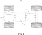
- Fig. 1 is a schematic structural view of a vehicle 1000 provided in some embodiments of the present application.
- the vehicle 1000 may be a fuel vehicle, a gas vehicle or a new energy vehicle.
- the new energy vehicle may be an all-electric vehicle, a hybrid vehicle, an extended-range vehicle, etc.
- the interior of the vehicle 1000 is provided with a battery 100.
- the battery 100 may be provided at the bottom or head or tail of the vehicle 1000.
- the battery 100 may be configured to supply power to the vehicle 1000.
- the battery 100 may be used as an operation power supply of the vehicle 1000.
- the vehicle 1000 may further include a controller 200 and a motor 300.
- the controller 200 is configured to control the battery 100 to power the motor 300.
- the controller is used for meeting the operating power demand when the vehicle 1000 is starting, navigating and driving.
- the battery 100 not only may serve as an operating power source of the vehicle 1000, but also may serve as a driving power source of the vehicle 1000, thus replacing or partially replacing fuel or natural gas to provide driving power for the vehicle 1000.
- Fig. 2 is a schematic structural view of a battery 100 according to some embodiments of the present application in an assembled state.
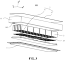
- Fig. 3 is a schematic exploded view of a battery 100 according to some embodiments of the present application.
- a battery 100 includes a box body 1, battery cells 2, and a stabilizing assembly 3.
- the box body 1 has a top 101 and a bottom 102 opposite to each other in a height direction of the box body 1.
- the plurality of battery cells 2 are arranged upside down in the box body 1, and a top cover plate 21 of each of the battery cells 2 is arranged to face the bottom 102 of the box body 1.
- the stabilizing assembly 3 is fixedly connected to the battery cells 2.
- the box body 1 having a top 101 and a bottom 102 opposite to each other in a height direction of the box body 1, it is meant that the top 101 and the bottom 102 of the box body 1 are arranged in sequence from top to bottom in the height direction.
- the height direction of the box body 1 is taken as the Z direction, that is, the vertical direction. It should be understood that the height direction Z of the box body 1 may also be along another direction, and other directions will be defined below in detail in order to indicate the arrangement direction of the battery cells 2 and other factors, and will not be further described here.
- the plurality of battery cells 2 being arranged upside down in the box body 1, and a top cover plate 21 of each of the battery cells 2 being arranged to face the top 101 of the box body 1, it is meant that the battery cells 2 and the box body 1 are arranged upside down with respect to each other in the height direction Z, and the bottom 102 of the battery cell 2 is located at the top 101 of the box body 1.
- the rigidity of the top 101 of the battery 100 can be increased, thereby increasing the safety of the battery 100.
- the top cover plate 21 of the battery cell 2 faces the bottom 102 of the battery 100, so that it is possible to increase the energy density of the battery 100 and improve the usability of the battery 100.
- the stabilizing assembly 3 is fixedly connected to the battery cells 2, that is, the stabilizing assembly 3 is fixedly connected to the bottom 102 and the top cover plate 21, namely two ends, of each battery cell 2, thereby supporting the battery cell 2 to increase the structural strength of the battery 100.
- the stabilizing assembly 3 includes a first support plate 31 and a second support plate 32, the first support plate 31 is arranged at the top 101 of the box body 1 and is fixedly connected to the battery cells 2, and the second support plate 32 is arranged at the bottom 102 of the box body 1 and is fixedly connected to the battery cells 2.
- the first support plate 31 and the second support plate 32 are arranged at the top 101 and the bottom 102 of the box body 1 respectively, and are fixedly connected to the battery cells 2 to fix the positions of the battery cells 2 and enhance the structural stability of the battery 100.
- the first support plate 31 may be located at the top 101 of the box body 1 as a part of the box body 1, or may be a separate plate body arranged between the box body 1 and the battery cells 2, with one side being fixedly connected to the box body 1 and the other side being fixedly connected to the battery cells 2, which will not be limited in the embodiments of the present application.
- the battery cells 2 may be directly bonded to the first support plate 31 and the second support plate 32 by means of glue, or may be fixedly connected to the first support plate 31 and the second support plate 32 in other ways.
- Fig. 4 is a schematic structural view of a second support plate 32 and suspension beams 321 of a battery 100 according to some embodiments of the present application.
- the surface of the second support plate 32 that faces the battery cells 2 is provided with a plurality of suspension beams 321, and the plurality of suspension beams 321 are arranged at intervals along the second support plate 32 in a length direction of the box body 1, and extend on the second support plate 32 in a width direction of the box body 1.
- the length direction of the box body 1 is taken as the X direction, and the width direction as the Y direction.
- the length direction X and the width direction Y are respectively perpendicular to the height direction Z. It can be understood that when the included angle between the length direction X, the height direction Z and the width direction Y is 85°-95°, the three are considered perpendicular to one another.
- the length direction X and the width direction Y may also be other directions, and the two may not be perpendicular to the height direction Z, which will not be described in the present application.
- the suspension beams 321 protrude from the second support plate 32 toward the battery cells 2 in the height direction Z, so as to support and carry the battery cells 2.
- the plurality of suspension beams 321 are arranged on the second support plate 32 at intervals in the length direction X, that is, the suspension beams 321 are arranged in the length direction X to support the battery cells 2 at a plurality of positions. Since the box body 1 is internally provided with a plurality of battery cells 2, the battery cells 2 are arranged in an array inside the box body 1, and the suspension beams 321 extend in the width direction Y, a single suspension beam 321 may support multiple battery cells 2 in the width direction Y
- the arrangement of the suspension beams 321 on the second support plate 32 can improve the structural stability of the battery 100 and prevent the top end cover of the battery 100 from directly abutting against the second support plate 32, which affects the performance of the battery 100.
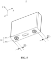
- Fig. 5 is a schematic structural view of a battery cell 2 according to an embodiment of the present application.
- the top cover plate 21 includes a functional area 201 and shoulders 202, the functional area 201 is provided with electrode terminals 211, the shoulders 202 are located on two sides of the functional area 201 in the length direction X, and the battery cell 2 is fixed to the suspension beams 321 via the shoulders 202.
- the functional area 201 indicates that the top cover plate 21 is provided with an area that enables the battery cell 2 to realize its own function, or an area that enables the battery cell 2 to interact with the outside, for example, the electrode terminals 211 that enable the battery cell 2 to be electrically connected to the outside. Since the functional area 201 is often provided with the electrode terminals 211 and other components, the functional area 201 should not be subjected to stress during the use of the battery 100.
- the shoulder 202 indicates the area of the top cover plate 21 that can be subjected to stress except the functional area 201.
- Arranging the functional area 201 provided with the electrode terminals 211 between the shoulders 202 can make the shoulders 202 achieve a certain protective effect on the functional area 201.
- the battery cell 2 is lap-jointed to the suspension beams 321 via the shoulders 202, so that it is possible to prevent the electrode terminals 211 of the functional area 201 from being damaged due to stress, and prolong the service life of the battery cell 2.
- the battery cell 2 may be directly bonded to the suspension beams 321 by means of glue, or may be fixedly connected to the suspension beams 321 in other ways, which will not be limited in the embodiments of the present application here.
- the electrode terminals 211 are arranged between two adjacent suspension beams 321, and the electrode terminals 211 are arranged spaced apart from the second support plate 32.
- the electrode terminals 211 of the functional area 201 are also located between the two adjacent suspension beams 321, and the electrode terminals 211 are arranged spaced apart from the second support plate 32, that is, the electrode terminals 311 are not in contact with the second support plate 32, the electrode terminals 211 can be considered as being suspended between the two suspension beams 321, so as to extract the electric energy from the battery cell 2 through the electrode terminals 211 and improve the usability of the battery cell 2.
- the suspension beam 321 in the height direction Z, has an extension height greater than those of the electrode terminal 211 and the pressure relief mechanism 212.
- the extension height of the suspension beam 321 is greater than that of the electrode terminal 211, so that the electrode terminals 211 and the pressure relief mechanism 212 can be suspended between the adjacent suspension beams 321, so as to avoid contact with other components to affect the function.
- the functional area 201 is further provided with a pressure relief mechanism 212, the pressure relief mechanism 212 is arranged spaced apart from the second support plate 32, and the electrode terminals 211 are arranged on two sides of the pressure relief mechanism 212 in the length direction X.
- the pressure relief mechanism 212 refers to an element or component that is actuated when an internal pressure of the battery cell 2 reaches a predetermined threshold so as to release the internal pressure. That is, when the internal pressure of the battery cell 2 reaches a predetermined threshold, the pressure relief mechanism 212 generates an action or is activated into a certain state, such that the internal pressure of the battery cell 2 can be released.
- the action generated by the pressure relief mechanism 212 may include, but not limited to, at least a part of the pressure relief mechanism 212 being fractured, broken, torn or opened, so as to form an opening 103, a channel or the like for releasing the internal pressure.
- the pressure relief mechanism 212 may take the form of an explosion-proof valve, a gas valve, a pressure relief valve, a safety valve or the like, and may specifically use a pressure sensitive element or structure.
- Arranging the electrode terminals 211 on two sides of the pressure relief mechanism 212 can reduce the influence of the pressure relief structure 212 on the electrode terminals 211 during pressure relief.
- the pressure relief mechanism 212 is arranged spaced apart from the second support plate 32, that is, the pressure relief mechanism 212 is not in contact with the second support plate 32, thereby providing a larger pressure relief space for the pressure relief mechanism 212, reducing the risk caused by the discharge of emissions. and improving the safety of the battery 100.
- the shoulders 202 of two adjacent battery cells 2 are jointly fixed to the same suspension beam 321.
- the plurality of battery cells 2 are arranged adjacent to each other in the box body 1. Since the suspension beams 321 are arranged at intervals along the second support plate 32 in the length direction X, the shoulders 202 are located on two sides of the functional area 201 in the length direction X, so that each shoulder 202 can be located at the connection between the adjacent battery cells 2, and the shoulders 202 of two adjacent battery cells 2 can thus be jointly fixed to the same suspension beam 321.
- the battery cells 2 adjacent to each other in the length direction X share the same suspension beam 321, so that it is possible to reduce the number of suspension beams 321 as much as possible and facilitate the manufacture of the second support plate 32.
- a width D1 of the suspension beam 321 and an extension width D2 of the shoulder 202 satisfy: 0.5D2 ⁇ D1 ⁇ 2D2.
- the width D1 of the suspension beam 321 is greater than or equal to 0.5 times the extension width D2 of the shoulder 202, sufficient support force can be provided for the battery cell 2.
- the width of the suspension beam 321 in the length direction X is less than or equal to 2 times the extension width of the shoulder 202, so that the suspension beam 321 can only be in contact with the shoulders 202 of the two adjacent battery cells 2, so as to avoid contact with the functional area 201 to affect the function of the battery cells 2.
- the relationship between the width D1 of the suspension beam 321 and the extension width D2 of the shoulder 202 may satisfy D2 ⁇ D1 ⁇ 2D2. Since the suspension beam 321 may be offset between adjacent battery cells 2, the width of the suspension beam 321 in the length direction X is greater than or equal to the extension width of the shoulder 202, so that the suspension beam 321 can carry two adjacent battery cells 2 at the same time, without the problem of poor structural stability of the battery 100 due to uneven stress when only one of the two adjacent battery cells can be carried due to offset.
- two adjacent battery cells 2 are electrically connected to each other via a bus component 24, and an extension length of one of two adjacent suspension beams 321 is less than that of the other in the width direction Y, to form an avoidance notch 322.
- the avoidance notch 322 is configured to avoid the bus component 24.
- the bus component 24 is a component that enables the electrical connection between the plurality of battery cells 2.
- the bus component 24 bridges the electrode terminals 211 of adjacent battery cells 2 to connect the plurality of battery cells 2 in series, in parallel or in series-parallel. Since, in the embodiments of the present application, the bus component 24 bridges the electrode terminals 211 of adjacent battery cells 2 in the length direction X, at least a part of the suspension beam 321 extending in the width direction Y needs to avoid the bus component, to form the avoidance notch 322.
- the extension length of one of the two adjacent suspension beams 321 is smaller than that of the other, that is, the suspension beams 321 with longer extension lengths and the suspension beams 321 with shorter extension lengths are alternately distributed.
- the lengths of the suspension beams 321 may also be adjusted according to the arrangement of the bus component 24.
- the extension length of the suspension beam 321 in the width direction Y merely indicates the total length of the suspension beam 321 in the width direction Y, that is to say, the avoidance notch 322 may be arranged at one end of the suspension beam 321, or may be arranged in the middle of the suspension beam 321, depending on the arrangement of the bus component 24, which will not be specially limited in the embodiments of the present application.
- Providing the avoidance notch 322 at the suspension beam 321 can make the suspension beam 321 better adapt to the structure of the battery 100, facilitating the series, parallel or series-parallel connection of the battery cells 2.
- the suspension beams 321 may be integrally formed with or detachably connected to the second support plate 32.
- suspension beams 321 are integrally formed with the second support plate 32, the manufacture of the second support plate 32 is facilitated. Where the suspension beams 321 are detachably connected to the second support plate 32, the positions of the suspension beams 321 can be adjusted according to the arrangement of the battery cells 2, so that the battery 100 has a more stable structure.
- the surfaces of the second support plate 32 and the suspension beams 321 are coated with an insulating material.
- the second support plate 32 and the suspension beams 321 are insulating members. It can be understood that the second support plate 32 and the suspension beams 321 each may be made of an insulating material as a whole, or each may be an object whose surface is coated with an insulating material so as to exhibit insulation properties as a whole.
- a core material may be a metal material, an insulating material, a composite material, etc., and an outer surface of the core material is covered with the insulating material.
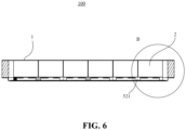
- Fig. 6 is a schematic cross-sectional view of the battery 100 shown in Fig. 2 .
- Fig. 7 is an enlarged schematic view of circle B in Fig. 6 .
- the extension height of the suspension beam 321 is a first dimension H1, the first dimension H1 satisfying 0.5 mm ⁇ H1 ⁇ 30 mm.
- the suspension beam 321 has a certain size in the height direction Z, so that it can protrude from the second support plate 32 to support and carry the battery cells 2.
- the suspension beam 321 maintains the first dimension H1, so that it is possible for the top cover plate 21 of the battery cell 2 to be kept at a certain distance from the bottom 102 of the box body 1, so as to keep the energy density of the battery 100 moderate.
- the ratio H1/M of the first dimension H1 to the weight M of a single battery cell 2 satisfies 0.05 mm/Kg ⁇ H1/M ⁇ 50 mm/Kg.
- the ratio H1/M of the first dimension H1 to the weight M of a single battery cell 2 can indicate the energy density and the structural strength of the battery 100.
- the ratio of the first dimension H1 to the weight M of a single battery cell 2 is too large, the energy density of the battery 100 will be too low accordingly.
- the ratio of the first dimension H1 to the weight M of a single battery cell 2 is too small, the structural strength of the battery 100 will be insufficient accordingly, and a safety accident may occur in a collision. Therefore, the ratio H1/M of the first distance H1 to the weight M of a single battery cell 2 satisfies 0.05 mm/Kg ⁇ H1/M ⁇ 50 mm/Kg. Within this value range, the battery 100 has a good energy density and an appropriate structural strength.
- a structural strength test may be performed on the battery 100.
- the structural strength of the battery 100 may be determined through a plurality of tests such as a shear strength test and a compressive strength test.
- the battery 100 may be fixed between clamps of a shear tester, then a detection head of the shear tester is used to drive the battery 100 to move in the length direction X or in the width direction Y at a speed of 5 mm/min, and a pulling force F exerted by the detection head is recorded when the box body 1 is damaged.
- a detection head of the shear tester is used to drive the battery 100 to move in the length direction X or in the width direction Y at a speed of 5 mm/min, and a pulling force F exerted by the detection head is recorded when the box body 1 is damaged.
- F/A Taking a projection area of the battery 100 in the height direction Z as an area A, the value of F/A is the shear strength that the battery 100 can withstand.
- a pressing head may be used to apply pressure to the battery 100 in the height direction Z and in the length direction X or in the width direction Y, advances toward the battery 100 at a speed of 2 m/s, and is stopped for 10 minutes after a pressing force reaches 50 KN or the deformation of the battery 100 reaches 30%, and the battery 100 is left standing and observed at the ambient temperature for 2 hours after the compressive strength test.
- the structural strength of the battery 100 may be tested through other structural strength tests, which will not be limited in the embodiments of the present application here.
- Table 1 shows the test results of the structural strength of the battery 100 by using the above method when the first distance H1, the weight M of a single battery cell 2 and the value of H1/M are respectively different.
- Table 1 H1 (mm) M (Kg) H1/M (mm/Kg) Structural strength test Example 1 0.5 10 0.05 Fair Example 2 5 5 1 Fair Example 3 10 4 2.5 Good Example 4 10 2 5 Good Example 5 20 1 20 Excellent Example 6 30 0.6 50 Fair Comparative Example 1 0.2 5 0.04 Poor Comparative Example 2 52 1 52 Poor
- the battery 100 has a better structural strength in the structural strength test.
- the battery cells 2 may not be fixedly connected to the suspension beams 321 of the second support plate 32, but only mounted on the suspension beams 321.
- the first dimension H1 satisfies 5 mm ⁇ H1 ⁇ 30 mm
- the ratio H1/M of the first dimension H1 to the weight M of a single battery cell 2 satisfies 0.5 mm/Kg ⁇ H1/M ⁇ 50 mm/Kg.
- H1/M satisfies 1 mm/Kg ⁇ H1/M ⁇ 30 mm/Kg.
- the battery 100 has a good energy density and an appropriate structural strength.
- Fig. 8 is a schematic structural view of a collision test device A for performing a collision test on a battery 100 according to some embodiments of the present application.
- a collision test is performed on the battery 100 by a collision test device A.
- the collision test device A includes an impact head A1, a launching device A2 and a rack A3.
- the battery 100 is placed on the rack A3, such that the impact head A1 is driven by the launching device A2, and impacts on the battery 100 at a certain speed.
- Test conditions may be selected as follows: an impact direction is the height direction Z, an impact position is a weak point of the battery 100, and an impact energy is 90J.
- the weak point of the battery 100 indicates a vulnerable position of the battery 100, which is usually within a radius of 240 mm from the geometric center of the battery 100, and impacting the weak point of the battery 100 which can simulate the state of the battery 100 after the position of the battery 100 that has a weak structural strength is impacted.
- the impact energy of 90J can be equivalent to the impact head A1 impacting the battery 100 at a speed of 4.2 m/s.
- another impact energy can also be used to impact the battery 100, for example, 120J (at an impact speed 4.9 m/s) or 150J (at an impact speed 5.5 m/s).
- 120J at an impact speed 4.9 m/s
- 150J at an impact speed 5.5 m/s
- the battery 100 may be impacted multiple times with one impact energy, or the battery 100 may be impacted multiple times with multiple impact energies.
- the battery 100 After the battery 100 is impacted by the collision test device A, it is observed at the ambient temperature for 2 hours to detect whether the battery 100 catches fire or explodes.
- the battery 100 may also be tested for the enclosure protection level, which will not be limited in the embodiments of the present application.
- Table 2 shows the test results of the collision test on the battery 100 by using the above method when the first distance H1, the weight M of a single battery cell 2 and the value of H1/M are respectively different, with the battery cells 2 being mounted on the suspension beams 321.
- Table 2 No. H1 (mm) M (Kg) H1/M (mm/Kg) Collision test Example 7 5 10 0.5 No fire, no explosion Example 8 10 5 2 No fire, no explosion Example 9 15 3 5 No fire, no explosion Example 10 30 1 30 No fire, no explosion Example 11 25 0.5 50 No fire, no explosion Comparative Example 3 3 5 0.2 Fire, explosion Comparative Example 4 52 1 52 Fire, explosion
- Fig. 9 is a schematic structural view of a cover body 4 of a battery 100 according to some embodiments of the present application.
- the box body 1 further includes a cover body 4 arranged at the bottom 102, and the cover body 4 is fixedly connected to the box body 1.
- the bottom 102 of the box body 1 When the bottom 102 of the box body 1 is provided with a cover body 4, that is, the bottom 102 of the box body 1 has an opening 103, the opening 103 faces downward in the height direction Z, and the cover body 4 covers the opening 103, so that the box body 1 has a relatively sealed structure.
- the cover body 4 includes a main body portion 41 and a matching portion 42.
- the matching portion 42 is arranged in a circumferential direction of the main body portion 41 and match the side plates 11. That is, the main body portion 41 covers the opening 103 formed by the side plates 11, and the matching portion 42 is fixed to the side plates 11 to fixedly connect the cover body 4 to the side plates 11.
- the matching portion 42 may be bolted to the side plate 11, or the matching portion 42 may be fixedly connected to the side plates 11 in other ways.
- the main body portion 41 protrudes from an extension plane of the bottom 102 relative to the matching portion 42.
- the protruding distance of the main body portion 41 relative to the matching portion 42 should be selected based on the energy density of the battery 100, and should not be too large to increase the volume of the battery 100 while reducing the energy density of the battery 100.
- the second support plate 32 may be fixedly connected to the cover body 4, to increase the structural firmness of the battery 100.
- the second support plate 32 may abut against the cover body 4, which will not be limited in the embodiments of the present application.
- the above descriptions of some embodiments of the battery 100 are only illustrative, and the battery 100 may also have other structures.
- the first support plate 31 is located at the top 101 of the box body 1 as a part of the box body 1.
- the box body 1 further includes side plates 11.
- the side plates 11 are distributed along the periphery of the opening 103 facing the bottom 102, and the first support plate 31 and the cover body 4 are respectively fixedly connected to the side plates 11. That is, the first support plate 31, the side plates 11 and the cover body 4 are arranged in sequence from top to bottom in the height direction Z, the first support plate 31 is a plate body extending in the length direction X, and the side plates 11 are plate bodies extending in the height direction Z.
- the side plates 11 are arranged around the first support plate 31, and the opening 103 is formed at the bottom 102.
- the cover body 4 covers the opening 103, so that the interior of the box body 1 has a space for arranging the battery cells 2.
- the battery cells 2 are arranged at the first support plate 31, so that it is possible to increase the rigidity of the top 101 of the battery 100 and reduce the possibility of damage to the battery 100 in a collision.
- the side plates 11 may be integrally formed with the first support plate 31, or may be fixedly connected to the first support plate 31 by welding, bonding, fastening, flow drill screwing process or other connection means, which will not be limited in the embodiments of the present application.
- a cooling channel (not shown in the figures) is buried inside the first support plate 31. Since the battery cells 2 are arranged at the first support plate 31, and the bottom 102 of each battery cell 2 is in contact with the first support plate 31, for the consideration of the performance of the battery 100, a cooling channel is buried inside the first support plate 31, and a cooling gas or liquid passes through the channel, so that it is possible to reduce the temperature of the battery 100 during operating of the battery 100, thereby prolonging the service life and improving the usability of the battery 100.
- a cooling channel may be provided between the battery cell 2 and the first support plate 31 as a water cooling plate, or be formed as any other component that can be configured to provide a temperature reduction effect, which will not be limited in the embodiments of the present application here.
- the box body 1 may be a simple three-dimensional structure such as a cuboid or a cylinder, or a complex three-dimensional structure composed of simple three-dimensional structures such as a cuboid or a cylinder.
- the material of the box body 1 may be an alloy material such as an aluminum alloy and an iron alloy, or may be a polymer material such as polycarbonate and polyisocyanurate foam, or may be a composite material such as a combination of glass fiber and epoxy resin.
- a sealing member such as a sealant and a sealing ring, may also be provided between the cover body 4 and the side plates 11.
- the above feasible configurations are not limited in the embodiments of the present application.
- a plurality of battery cells 2 may be connected in series, in parallel or in series-parallel.
- the series-parallel connection means that some of the plurality of battery cells 2 are connected in series and some are connected in parallel.
- a plurality of battery cells 2 may be directly connected in series or in parallel or in series-parallel, and then an entirety composed of the plurality of battery cells 2 may be accommodated in the box body 1.
- the battery 100 may alternatively consist in that a plurality of battery cells 2 are first connected in series, in parallel or in series-parallel to form a plurality of battery 100 modules, and the plurality of battery 100 modules are then connected in series or in parallel or in series-parallel to form a whole, and are accommodated in the box body 1.
- Each battery cell 2 may be a secondary battery or a primary battery; or may be a lithium-sulfur battery, a sodium-ion battery or a magnesium-ion battery, but is not limited thereto.
- the battery cell 2 may be in the shape of a cylinder, a flat body, a cuboid or others.
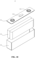
- Fig. 10 is a schematic structural view of the interior of a battery cell 2 according to some embodiments of the present application.
- the battery cell 2 is the smallest unit constituting the battery 100.
- the battery cell 2 further includes a top cover plate 21, a case 22, an electrode assembly 23 and other functional components.
- the top cover plate 21 is a component that covers the opening of the case 22 to isolate the internal environment of the battery cell 2 from the external environment.
- the shape of the top cover plate 21 may be adapted to the shape of the case 22 to match the case 22.
- the top cover plate 21 may be made of a material (such as an aluminum alloy) with a certain hardness and strength, so that the top cover plate 21 is not easy to be deformed when being pressed and collided, the battery cell 2 can have a higher structural strength, and the safety performance can also be improved.
- the top cover plate 21 is provided with functional components such as electrode terminals 211 and an explosion-proof valve.
- the electrode terminals 211 may be used for electrical connection with the electrode assembly 23 for outputting or inputting electric energy of the battery cell 2.
- the top cover plate 21 may also be provided with a pressure relief mechanism 212 for releasing the internal pressure when the internal pressure or temperature of the battery cell 2 reaches a threshold value.
- the top cover plate 21 may be made of various materials, such as copper, iron, aluminum, stainless steel, an aluminum alloy, and plastic, which will not be specially limited in the embodiments of the present application.
- an insulating member may be also provided on the inner side of the top cover plate 21, and the insulating member may be used to isolate an electrical connection plate in the case 22 from the top cover plate 21 to reduce the risk of short circuit.
- the insulating member may be made of plastic, rubber or the like.
- the case 22 is an assembly for matching the top cover plate 21 to form the internal environment of the battery cell 2.
- the formed internal environment may be used to accommodate the electrode assembly 23, an electrolyte solution (not shown in the figures) and other components.
- the case 22 and the top cover plate 21 may be separate components, the case 22 may be provided with an opening, and the internal environment of the battery cell 2 is formed by making the top cover plate 21 cover the opening at the opening.
- the top cover plate 21 and the case 22 may also be integrated with each other.
- the top cover plate 21 and the case 22 may form a common connection face before other components are inserted into the case. When the interior of the case 22 needs to be packaged, the top cover plate 21 then covers the case 22.
- the case 22 may have various shapes and sizes, such as a cuboid, a cylinder and a hexagonal prism. Specifically, the case 22 may be shaped according to the specific shape and size of the electrode assembly 23.
- the case 22 may be made of various materials, such as copper, iron, aluminum, stainless steel, an aluminum alloy, and plastic, which will not be specially limited in the embodiments of the present application.
- the electrode assembly 23 is a component of a battery cell 2 where an electrochemical reaction occurs.
- One or more electrode assemblies 23 may be contained in the case 22.
- the electrode assembly 23 is mainly formed by winding or stacking a positive electrode sheet and a negative electrode sheet, and a separator is generally provided between the positive electrode sheet and the negative electrode sheet.
- the parts of the positive electrode sheet and the negative electrode sheet having active materials constitute a main body portion of the electrode assembly 23, and the parts of the positive electrode sheet and the negative electrode sheet having no active materials respectively constitute tabs.
- the positive tab and the negative tab may be located at one end of the main portion together or at two ends of the main body portion respectively.
- the battery 100 includes a box body 1, a plurality of battery cells 2 and a stabilizing assembly 3.
- the battery cells 2 are arranged upside down in the box body 1, and a top cover plate 21 faces the bottom 102 of the box body 1 in a height direction Z.
- the stabilizing assembly 3 includes a first support plate 31 and a second support plate 32, the first support plate 3 is arranged at the top 101 of the box body 1 in the height direction Z and is fixedly connected to the battery cells 2, and the second support plate 32 is arranged at the bottom 102 of the box body 1 and is fixedly connected to the battery cells 2.
Landscapes
- Chemical & Material Sciences (AREA)
- Chemical Kinetics & Catalysis (AREA)
- Electrochemistry (AREA)
- General Chemical & Material Sciences (AREA)
- Engineering & Computer Science (AREA)
- Aviation & Aerospace Engineering (AREA)
- Manufacturing & Machinery (AREA)
- Battery Mounting, Suspending (AREA)
- Connection Of Batteries Or Terminals (AREA)
Abstract
Description
- The present application relates to the technical field of batteries, and in particular to a battery and an electrical device.
- In recent years, the emergence of new energy vehicles has played a huge role in promoting social development and environmental protection. Power batteries, which are rechargeable batteries, are the power source of new energy vehicles and are widely used in the field of new energy vehicles.
- In the prior art, the energy density of the battery is not high, resulting in waste of space, which in turn affects the performance of the electrical apparatus. Moreover, the existing battery has poor rigidity, cannot directly bear the load brought by other parts of the electrical apparatus, and is likely to cause safety accidents and affects the safety of the electrical apparatus.
- Embodiments of the present application provide a battery and an electrical apparatus, which can improve the energy density and the safety of the battery.
- In a first aspect, the embodiments of the present application provide a battery, including a box body, battery cells, and a stabilizing assembly. The box body has a top and a bottom opposite to each other in a height direction of the box body. A plurality of battery cells are arranged upside down in the box body, and a top cover plate of each of the battery cells is arranged to face the bottom of the box body. The stabilizing assembly is fixedly connected to the battery cells.
- In the above technical solution, the box body has the top and the bottom opposite to each other in the height direction, and the top cover plate of each of the battery cells is arranged to face the bottom of the box body, so that the energy density of the battery can be improved, and the arrangement of the stabilizing assembly fixedly connected to the battery cells can improve the structural stability of the battery.
- In some embodiments, the stabilizing assembly includes a first support plate and a second support plate, the first support plate is arranged at the top of the box body and is fixedly connected to the battery cells, and the second support plate is arranged at the bottom of the box body and is fixedly connected to the battery cells, so as to fix the positions of the battery cells.
- In some embodiments, the surface of the second support plate that faces the battery cells is provided with a plurality of suspension beams, and the plurality of suspension beams are arranged at intervals along the second support plate in a length direction of the box body, and extend on the second support plate in a width direction of the box body.
- In the above technical solution, the top end cover of the battery is prevented from directly abutting against the second support plate, which affects the performance of the battery.
- In some embodiments, the top cover plate includes a functional area and shoulders, the functional area is provided with electrode terminals, the shoulders are located on two sides of the functional area in the length direction, and the battery cell is fixedly connected to the suspension beams via the shoulders.
- In the above technical solution, the functional area is located between the shoulders, so that the shoulders can achieve a certain protective effect on the functional area. The battery cell is lap-jointed to the suspension beams by means of the shoulders, so that it is possible to prevent damage to the functional area due to stress, and prolong the service life of the battery cell.
- In some embodiments, the electrode terminals are arranged between two adjacent suspension beams, and the electrode terminals are arranged spaced apart from the second support plate.
- In the above technical solution, the electrode terminals are prevented from being in contact with the second support plate, so as to facilitate the electrical connection between the electrode terminals and the outside.
- In some embodiments, in the height direction, the suspension beam has an extension height greater than that of the electrode terminal.
- In the above technical solution, the electrode terminals are suspended between the suspension beams.
- In some embodiments, the functional area is further provided with a pressure relief mechanism, the pressure relief mechanism is arranged spaced apart from the second support plate, and the electrode terminals are arranged on two sides of the pressure relief mechanism in the length direction.
- In the above technical solution, the pressure relief mechanism is arranged spaced apart from the second support plate, so that it is possible to provide a larger pressure relief space for the pressure relief mechanism, reduce the risk caused by the discharge of emissions, and improve the safety of the battery.
- In some embodiments, the shoulders of two adjacent battery cells are jointly fixed to the same suspension beam.
- In the above technical solution, the adjacent battery cells share the same suspension beam, so that it is possible to reduce the number of suspension beams as much as possible and facilitate the manufacture of the second support plate.
- In some embodiments, in the length direction, a width D1 of the suspension beam and an extension width D2 of the shoulder satisfy: 0.5D2 ≤ D1 ≤ 2D2.
- In the above technical solution, the suspension beam is prevented from carrying only the battery cell on one side due to offset, and the suspension beam is only in contact with the shoulders of two adjacent battery cells, while avoiding contact with the functional area to affect the function of the battery cell.
- In some embodiments, two adjacent battery cells are electrically connected to each other via a bus component, and an extension length of one of two adjacent suspension beams is less than that of the other in the width direction, to form an avoidance notch, the avoidance notch being configured to avoid the bus component.
- In the above technical solution, the suspension beam is better adapted to the structure of the battery, facilitating the series connection, parallel or series-parallel of the battery cells.
- In some embodiments, the suspension beams are integrally formed with or detachably connected to the second support plate, so as to facilitate the manufacture of the suspension beams or adjust the positions of the suspension beams according to the arrangement of the battery cells.
- In some embodiments, in the height direction, an extension height of the suspension beam is a first dimension H1, the first dimension H1 satisfying 0.5 mm ≤ H1 ≤ 30 mm, so as to keep the volume of the battery moderate.
- In some embodiments, a ratio H1/M of the first dimension H1 to the weight M of a single battery cell satisfies 0.05 mm/Kg ≤ H1/M ≤ 50 mm/ Kg.
- In the above technical solution, the battery has a good energy density and an appropriate structural strength.
- In some embodiments, the box body further includes a cover body arranged at the bottom, and the cover body is fixedly connected to the box body.
- In some embodiments, the second support plate is fixedly connected to the cover body to increase the structural firmness of the battery.
- In a second aspect, the embodiments of the present application provide an electrical apparatus, including a battery cell according to any one of the embodiments in the first aspect, the battery cell being configured to supply electric energy.
- In order to more clearly illustrate the technical solutions of the embodiments of the present application, the drawings to be used in the description of the embodiments of the present application will be described briefly below. Obviously, the drawings in the following description are merely some embodiments of the present application. For those skilled in the art, other drawings can also be obtained according to these drawings without any creative effort.
-
Fig. 1 is a schematic structural view of a vehicle provided in some embodiments of the present application; -
Fig. 2 is a schematic structural view of a battery according to some embodiments of the present application in an assembled state; -
Fig. 3 is a schematic exploded view of a battery according to some embodiments of the present application; -
Fig. 4 is a schematic structural view of a second support plate and suspension beams of a battery according to some embodiments of the present application; -
Fig. 5 is a schematic structural view of a battery cell according to some embodiments of the present application; -
Fig. 6 is a schematic cross-sectional view of the battery shown inFig. 2 ; -
Fig. 7 is an enlarged schematic view of circle B inFig. 6 ; -
Fig. 8 is a schematic structural view of a collision test device for performing a collision test on a battery according to some embodiments of the present application; -
Fig. 9 is a schematic structural view of a cover body of a battery according to some embodiments of the present application; and -
Fig. 10 is a schematic structural view of the interior of a battery cell according to some embodiments of the present application. - The reference signs in Detailed Description are as follows:
- 1000, vehicle; 100, battery; 200, controller; 300, motor; 1, box body; 101, top; 102, bottom; 103, opening; 11, side plate; 2, battery cell; 201, functional area; 202, shoulder; 21, top cover plate; 211, electrode terminal; 212, pressure relief mechanism; 22, case; 23, electrode assembly; 24, bus component; 3, stabilizing assembly; 31, first support plate; 32. second support plate; 321, suspension beam; 322, avoidance notch; 4, cover body; 41, main body portion; 42, matching portion;
- X, length direction; Y, width direction; Z, height direction.
- In order to make the objects, technical solutions and advantages of embodiments of the present application clearer, the technical solutions in the embodiments of the present application will be clearly described below with reference to the drawings for the embodiments of the present application. Apparently, the described embodiments are some of, rather than all of, the embodiments of the present application. All the other embodiments obtained by a person of ordinary skill in the art based on the embodiments of the present application without any creative effort shall fall within the scope of protection of the present application.
- Unless otherwise defined, all technical and scientific terms used in the present application have the same meanings as those commonly understood by those skilled in the art to which the present application belongs. The terms used in the specification of the present application are merely for the purpose of describing specific embodiments, but are not intended to limit the present application. The terms "comprising" and "having" and any variations thereof in the specification and the claims of the present application as well as the foregoing description of the drawings are intended to cover non-exclusive inclusions. The terms "first", "second" and the like in the specification and the claims of the present application as well as the above drawings are used to distinguish different objects, rather than to describe a specific order or primary-secondary relationship.
- The phrase "embodiment" referred to in the present application means that the descriptions of specific features, structures, and characteristics in combination with the embodiment are included in at least one embodiment of the present application. The appearance of this phrase in various places in the specification does not necessarily refer to the same embodiment, nor is it a separate or alternative embodiment that is mutually exclusive with other embodiments.
- In the description of the present application, it should be noted that the terms "mounting", "connecting", "connection" and "attachment" should be understood in a broad sense, unless otherwise explicitly specified or defined, for example, it may be a fixed connection, a detachable connection or an integrated connection; and may be a direct connection or an indirect connection through an intermediate medium, or may be a communication between the interior of two elements. For those of ordinary skill in the art, the specific meanings of the above terms in the present application can be understood according to specific situations.
- In the present application, the term "and/or" is only an association relationship for describing associated objects, indicating that three relationships may exist. For example, A and/or B may represent three situations: A exists alone, both A and B exist, and B exists alone. In addition, the character "/" in the present application generally means that the associated objects before and after it are in an "or" relationship.
- In the embodiments of the present application, the same reference signs denote the same components, and for the sake of brevity, detailed descriptions of the same components are omitted in different embodiments. It should be understood that the thickness, length, width and other dimensions of the various components in the embodiments of the present application shown in the drawings, as well as the overall thickness, length, width and other dimensions of an integrated apparatus, are for illustrative purposes only, and should not constitute any limitation to the present application.
- In the present application, the phrase "a plurality of" means two or more (including two).
- The term "parallel" in the present application includes not only the absolutely parallel situation, but also the roughly parallel situation that is generally recognized in engineering; moreover, the term "perpendicular" not only includes the absolutely perpendicular situation, but also includes the roughly perpendicular situation that is generally recognized in engineering.
- In the present application, the battery cell may include a lithium-ion secondary battery cell, a lithium-ion primary battery cell, a lithium sulfur battery cell, a sodium lithium-ion battery cell, a sodium-ion battery cell, a magnesium-ion battery cell, or the like, which will not be limited in the embodiments of the present application.
- In the present application, the battery refers to a single physical module that includes one or more battery cells to provide higher voltage and capacity. For example, the battery mentioned in the present application may be a battery module, a battery pack, or the like. The battery generally includes a box body for packaging one or more battery cells. The box body can prevent liquid or other foreign matters from affecting charging or discharging of the battery cells. In the battery, a plurality of battery cells may be connected in series, in parallel or in series-parallel. The series-parallel connection means that some of the plurality of battery cells are connected in series and some are connected in parallel. A plurality of battery cells may be directly connected in series or in parallel or in series-parallel, and then an entirety composed of the plurality of battery cells may be accommodated in the box body. Of course, the battery may alternatively consist in that a plurality of battery cells are first connected in series, in parallel or in series-parallel to form a plurality of batteries, and the plurality of batteries are then connected in series or in parallel or in series-parallel to form a whole, and are accommodated in the box body.
- At present, from the development of market situation, the application of traction batteries is becoming more and more extensive. Power batteries are used in energy storage power source systems such as hydraulic, thermal, wind and solar power stations as well as in electric vehicles such as electric bicycles, electric motorcycles and electric cars, and military equipment and aerospace fields. With the continuous expansion of the application field of the power batteries, the market demand is also constantly expanding.
- In the related art, the opening of the box body of the battery usually faces upward in the vertical direction, the battery cells are fixed to the bottom of the battery, and electrode terminals face a cover body which covers the opening of the box body.
- However, in the battery configured as above, the inventors have noticed that when the battery is arranged in an electrical apparatus, the bottom is bonded to the electrical apparatus, and the battery cells are fixed to the bottom of the battery, so that the top of the battery that is more vulnerable to collisions has a poor rigidity, and when the battery is in a collision, the battery cells therein are subjected to uneven stress, so that the battery likely to be damaged, resulting in poor safety of the battery and affecting the performance of the battery.
- In view of this, the embodiments of the present application provide a battery, in which a box body has a top and a bottom opposite to each other in a height direction, and a top cover plate of each of battery cells is arranged to face the bottom of the box body, so that the energy density of the battery can be improved, and the arrangement of a stabilizing assembly fixedly connected to the battery cells can improve the structural stability of the battery.
- The technical solutions described in the embodiments of the present application are applicable to batteries and electrical apparatus powered by the batteries.
- The electrical apparatus may be, but not limited to, a vehicle, a mobile phone, a portable device, a laptop, a ship, a spacecraft, an electric toy, an electric tool, and so on. The vehicle may be a fuel vehicle, a gas vehicle or a new energy vehicle. The new energy vehicle may be an all-electric vehicle, a hybrid electric vehicle, an extended-range vehicle, or the like. The spacecraft includes airplanes, rockets, space shuttles, spaceships, and the like. The electric toy includes fixed or mobile electric toys, such as game consoles, electric car toys, electric ship toys and electric aircraft toys. The electric tool includes metal cutting electric tools, grinding electric tools, assembly electric tools and railway electric tools, such as electric drills, electric grinders, electric wrenches, electric screwdrivers, electric hammers, impact drills, concrete vibrators and electric planers. The electrical apparatus is not specially limited in the embodiments of the present application.
- It should be understood that the technical solutions described in the embodiments of the present application are not merely applicable to the electrical apparatus described above. However, for the sake of brevity, the following embodiments will be described by taking an
electric vehicle 1000 as an example. -
Fig. 1 is a schematic structural view of avehicle 1000 provided in some embodiments of the present application. As shown inFig. 1 , thevehicle 1000 may be a fuel vehicle, a gas vehicle or a new energy vehicle. The new energy vehicle may be an all-electric vehicle, a hybrid vehicle, an extended-range vehicle, etc. The interior of thevehicle 1000 is provided with abattery 100. Thebattery 100 may be provided at the bottom or head or tail of thevehicle 1000. - The
battery 100 may be configured to supply power to thevehicle 1000. For example, thebattery 100 may be used as an operation power supply of thevehicle 1000. Thevehicle 1000 may further include acontroller 200 and amotor 300. Thecontroller 200 is configured to control thebattery 100 to power themotor 300. For example, the controller is used for meeting the operating power demand when thevehicle 1000 is starting, navigating and driving. In some embodiments of the present application, thebattery 100 not only may serve as an operating power source of thevehicle 1000, but also may serve as a driving power source of thevehicle 1000, thus replacing or partially replacing fuel or natural gas to provide driving power for thevehicle 1000. -
Fig. 2 is a schematic structural view of abattery 100 according to some embodiments of the present application in an assembled state.Fig. 3 is a schematic exploded view of abattery 100 according to some embodiments of the present application. As shown inFigs. 2 and3 , in some embodiments of the present application, abattery 100 includes abox body 1,battery cells 2, and a stabilizingassembly 3. Thebox body 1 has a top 101 and a bottom 102 opposite to each other in a height direction of thebox body 1. The plurality ofbattery cells 2 are arranged upside down in thebox body 1, and atop cover plate 21 of each of thebattery cells 2 is arranged to face thebottom 102 of thebox body 1. The stabilizingassembly 3 is fixedly connected to thebattery cells 2. - By the
box body 1 having a top 101 and a bottom 102 opposite to each other in a height direction of thebox body 1, it is meant that the top 101 and thebottom 102 of thebox body 1 are arranged in sequence from top to bottom in the height direction. For the convenience of description, in the embodiments of the present application, the height direction of thebox body 1 is taken as the Z direction, that is, the vertical direction. It should be understood that the height direction Z of thebox body 1 may also be along another direction, and other directions will be defined below in detail in order to indicate the arrangement direction of thebattery cells 2 and other factors, and will not be further described here. - By the plurality of
battery cells 2 being arranged upside down in thebox body 1, and atop cover plate 21 of each of thebattery cells 2 being arranged to face the top 101 of thebox body 1, it is meant that thebattery cells 2 and thebox body 1 are arranged upside down with respect to each other in the height direction Z, and thebottom 102 of thebattery cell 2 is located at the top 101 of thebox body 1. By arranging thebattery cells 2 and thebox body 1 upside down with respect to each other, the rigidity of the top 101 of thebattery 100 can be increased, thereby increasing the safety of thebattery 100. Moreover, thetop cover plate 21 of thebattery cell 2 faces thebottom 102 of thebattery 100, so that it is possible to increase the energy density of thebattery 100 and improve the usability of thebattery 100. - The stabilizing
assembly 3 is fixedly connected to thebattery cells 2, that is, the stabilizingassembly 3 is fixedly connected to the bottom 102 and thetop cover plate 21, namely two ends, of eachbattery cell 2, thereby supporting thebattery cell 2 to increase the structural strength of thebattery 100. - In some embodiments of the present application, the stabilizing
assembly 3 includes afirst support plate 31 and asecond support plate 32, thefirst support plate 31 is arranged at the top 101 of thebox body 1 and is fixedly connected to thebattery cells 2, and thesecond support plate 32 is arranged at the bottom 102 of thebox body 1 and is fixedly connected to thebattery cells 2. - The
first support plate 31 and thesecond support plate 32 are arranged at the top 101 and thebottom 102 of thebox body 1 respectively, and are fixedly connected to thebattery cells 2 to fix the positions of thebattery cells 2 and enhance the structural stability of thebattery 100. - Optionally, the
first support plate 31 may be located at the top 101 of thebox body 1 as a part of thebox body 1, or may be a separate plate body arranged between thebox body 1 and thebattery cells 2, with one side being fixedly connected to thebox body 1 and the other side being fixedly connected to thebattery cells 2, which will not be limited in the embodiments of the present application. - Optionally, the
battery cells 2 may be directly bonded to thefirst support plate 31 and thesecond support plate 32 by means of glue, or may be fixedly connected to thefirst support plate 31 and thesecond support plate 32 in other ways. -
Fig. 4 is a schematic structural view of asecond support plate 32 andsuspension beams 321 of abattery 100 according to some embodiments of the present application. As shown inFig. 4 , in some embodiments of the present application, the surface of thesecond support plate 32 that faces thebattery cells 2 is provided with a plurality of suspension beams 321, and the plurality ofsuspension beams 321 are arranged at intervals along thesecond support plate 32 in a length direction of thebox body 1, and extend on thesecond support plate 32 in a width direction of thebox body 1. - For the convenience of description, in the embodiments of the present application, the length direction of the
box body 1 is taken as the X direction, and the width direction as the Y direction. The length direction X and the width direction Y are respectively perpendicular to the height direction Z. It can be understood that when the included angle between the length direction X, the height direction Z and the width direction Y is 85°-95°, the three are considered perpendicular to one another. The length direction X and the width direction Y may also be other directions, and the two may not be perpendicular to the height direction Z, which will not be described in the present application. - The suspension beams 321 protrude from the
second support plate 32 toward thebattery cells 2 in the height direction Z, so as to support and carry thebattery cells 2. The plurality ofsuspension beams 321 are arranged on thesecond support plate 32 at intervals in the length direction X, that is, the suspension beams 321 are arranged in the length direction X to support thebattery cells 2 at a plurality of positions. Since thebox body 1 is internally provided with a plurality ofbattery cells 2, thebattery cells 2 are arranged in an array inside thebox body 1, and the suspension beams 321 extend in the width direction Y, asingle suspension beam 321 may supportmultiple battery cells 2 in the width direction Y - The arrangement of the suspension beams 321 on the
second support plate 32 can improve the structural stability of thebattery 100 and prevent the top end cover of thebattery 100 from directly abutting against thesecond support plate 32, which affects the performance of thebattery 100. -
Fig. 5 is a schematic structural view of abattery cell 2 according to an embodiment of the present application. As shown inFig. 5 , in some embodiments of the present application, thetop cover plate 21 includes afunctional area 201 andshoulders 202, thefunctional area 201 is provided withelectrode terminals 211, theshoulders 202 are located on two sides of thefunctional area 201 in the length direction X, and thebattery cell 2 is fixed to the suspension beams 321 via theshoulders 202. - The
functional area 201 indicates that thetop cover plate 21 is provided with an area that enables thebattery cell 2 to realize its own function, or an area that enables thebattery cell 2 to interact with the outside, for example, theelectrode terminals 211 that enable thebattery cell 2 to be electrically connected to the outside. Since thefunctional area 201 is often provided with theelectrode terminals 211 and other components, thefunctional area 201 should not be subjected to stress during the use of thebattery 100. Theshoulder 202 indicates the area of thetop cover plate 21 that can be subjected to stress except thefunctional area 201. - Arranging the
functional area 201 provided with theelectrode terminals 211 between theshoulders 202 can make theshoulders 202 achieve a certain protective effect on thefunctional area 201. Thebattery cell 2 is lap-jointed to the suspension beams 321 via theshoulders 202, so that it is possible to prevent theelectrode terminals 211 of thefunctional area 201 from being damaged due to stress, and prolong the service life of thebattery cell 2. - Optionally, the
battery cell 2 may be directly bonded to the suspension beams 321 by means of glue, or may be fixedly connected to the suspension beams 321 in other ways, which will not be limited in the embodiments of the present application here. - In some embodiments of the present application, the
electrode terminals 211 are arranged between two adjacent suspension beams 321, and theelectrode terminals 211 are arranged spaced apart from thesecond support plate 32. - Since the
functional area 201 is located between the twoshoulders 202, theshoulders 202 are lap-jointed to the suspension beams 321, theelectrode terminals 211 of thefunctional area 201 are also located between the two adjacent suspension beams 321, and theelectrode terminals 211 are arranged spaced apart from thesecond support plate 32, that is, the electrode terminals 311 are not in contact with thesecond support plate 32, theelectrode terminals 211 can be considered as being suspended between the twosuspension beams 321, so as to extract the electric energy from thebattery cell 2 through theelectrode terminals 211 and improve the usability of thebattery cell 2. - In some embodiments of the present application, in the height direction Z, the
suspension beam 321 has an extension height greater than those of theelectrode terminal 211 and thepressure relief mechanism 212. - In the height direction Z, the extension height of the
suspension beam 321 is greater than that of theelectrode terminal 211, so that theelectrode terminals 211 and thepressure relief mechanism 212 can be suspended between the adjacent suspension beams 321, so as to avoid contact with other components to affect the function. - In some embodiments of the present application, the
functional area 201 is further provided with apressure relief mechanism 212, thepressure relief mechanism 212 is arranged spaced apart from thesecond support plate 32, and theelectrode terminals 211 are arranged on two sides of thepressure relief mechanism 212 in the length direction X. - The
pressure relief mechanism 212 refers to an element or component that is actuated when an internal pressure of thebattery cell 2 reaches a predetermined threshold so as to release the internal pressure. That is, when the internal pressure of thebattery cell 2 reaches a predetermined threshold, thepressure relief mechanism 212 generates an action or is activated into a certain state, such that the internal pressure of thebattery cell 2 can be released. The action generated by thepressure relief mechanism 212 may include, but not limited to, at least a part of thepressure relief mechanism 212 being fractured, broken, torn or opened, so as to form anopening 103, a channel or the like for releasing the internal pressure. In this case, high-temperature and high-pressure substances inside thebattery cell 2 are discharged outwards from an actuated position as emissions. In this way, the pressure in thebattery cell 2 can be released at a controllable pressure, thereby avoiding potential, more serious accidents. Thepressure relief mechanism 212 may take the form of an explosion-proof valve, a gas valve, a pressure relief valve, a safety valve or the like, and may specifically use a pressure sensitive element or structure. - Arranging the
electrode terminals 211 on two sides of thepressure relief mechanism 212 can reduce the influence of thepressure relief structure 212 on theelectrode terminals 211 during pressure relief. Moreover, thepressure relief mechanism 212 is arranged spaced apart from thesecond support plate 32, that is, thepressure relief mechanism 212 is not in contact with thesecond support plate 32, thereby providing a larger pressure relief space for thepressure relief mechanism 212, reducing the risk caused by the discharge of emissions. and improving the safety of thebattery 100. - In some embodiments of the present application, the
shoulders 202 of twoadjacent battery cells 2 are jointly fixed to thesame suspension beam 321. - Where a plurality of
battery cells 2 are arranged in thebox body 1, the plurality ofbattery cells 2 are arranged adjacent to each other in thebox body 1. Since the suspension beams 321 are arranged at intervals along thesecond support plate 32 in the length direction X, theshoulders 202 are located on two sides of thefunctional area 201 in the length direction X, so that eachshoulder 202 can be located at the connection between theadjacent battery cells 2, and theshoulders 202 of twoadjacent battery cells 2 can thus be jointly fixed to thesame suspension beam 321. - The
battery cells 2 adjacent to each other in the length direction X share thesame suspension beam 321, so that it is possible to reduce the number ofsuspension beams 321 as much as possible and facilitate the manufacture of thesecond support plate 32. - In some embodiments of the present application, in the length direction X, a width D1 of the
suspension beam 321 and an extension width D2 of theshoulder 202 satisfy: 0.5D2 ≤ D1 ≤ 2D2. - When the width D1 of the
suspension beam 321 is greater than or equal to 0.5 times the extension width D2 of theshoulder 202, sufficient support force can be provided for thebattery cell 2. When thesuspension beam 321 carries twoadjacent battery cells 2 at the same time, the width of thesuspension beam 321 in the length direction X is less than or equal to 2 times the extension width of theshoulder 202, so that thesuspension beam 321 can only be in contact with theshoulders 202 of the twoadjacent battery cells 2, so as to avoid contact with thefunctional area 201 to affect the function of thebattery cells 2. - Preferably, the relationship between the width D1 of the
suspension beam 321 and the extension width D2 of theshoulder 202 may satisfy D2 ≤ D1 ≤ 2D2. Since thesuspension beam 321 may be offset betweenadjacent battery cells 2, the width of thesuspension beam 321 in the length direction X is greater than or equal to the extension width of theshoulder 202, so that thesuspension beam 321 can carry twoadjacent battery cells 2 at the same time, without the problem of poor structural stability of thebattery 100 due to uneven stress when only one of the two adjacent battery cells can be carried due to offset. - Referring to
Fig. 4 again, as shown inFig. 4 , in some embodiments of the present application, twoadjacent battery cells 2 are electrically connected to each other via abus component 24, and an extension length of one of two adjacent suspension beams 321 is less than that of the other in the width direction Y, to form anavoidance notch 322. Theavoidance notch 322 is configured to avoid thebus component 24. - The
bus component 24 is a component that enables the electrical connection between the plurality ofbattery cells 2. Thebus component 24 bridges theelectrode terminals 211 ofadjacent battery cells 2 to connect the plurality ofbattery cells 2 in series, in parallel or in series-parallel. Since, in the embodiments of the present application, thebus component 24 bridges theelectrode terminals 211 ofadjacent battery cells 2 in the length direction X, at least a part of thesuspension beam 321 extending in the width direction Y needs to avoid the bus component, to form theavoidance notch 322. - The extension length of one of the two adjacent suspension beams 321 is smaller than that of the other, that is, the suspension beams 321 with longer extension lengths and the suspension beams 321 with shorter extension lengths are alternately distributed. Optionally, the lengths of the suspension beams 321 may also be adjusted according to the arrangement of the
bus component 24. Moreover, the extension length of thesuspension beam 321 in the width direction Y merely indicates the total length of thesuspension beam 321 in the width direction Y, that is to say, theavoidance notch 322 may be arranged at one end of thesuspension beam 321, or may be arranged in the middle of thesuspension beam 321, depending on the arrangement of thebus component 24, which will not be specially limited in the embodiments of the present application. - Providing the
avoidance notch 322 at thesuspension beam 321 can make thesuspension beam 321 better adapt to the structure of thebattery 100, facilitating the series, parallel or series-parallel connection of thebattery cells 2. - In some embodiments of the present application, the suspension beams 321 may be integrally formed with or detachably connected to the
second support plate 32. - Where the suspension beams 321 are integrally formed with the
second support plate 32, the manufacture of thesecond support plate 32 is facilitated. Where the suspension beams 321 are detachably connected to thesecond support plate 32, the positions of the suspension beams 321 can be adjusted according to the arrangement of thebattery cells 2, so that thebattery 100 has a more stable structure. - In some optional embodiments, the surfaces of the
second support plate 32 and the suspension beams 321 are coated with an insulating material. - In order to avoid affecting the electrical connection between the
battery cells 2, thesecond support plate 32 and the suspension beams 321 are insulating members. It can be understood that thesecond support plate 32 and the suspension beams 321 each may be made of an insulating material as a whole, or each may be an object whose surface is coated with an insulating material so as to exhibit insulation properties as a whole. When thesecond support plate 32 and the suspension beams 321 each are an object whose surface is covered with an insulating material, a core material may be a metal material, an insulating material, a composite material, etc., and an outer surface of the core material is covered with the insulating material. -
Fig. 6 is a schematic cross-sectional view of thebattery 100 shown inFig. 2 .Fig. 7 is an enlarged schematic view of circle B inFig. 6 . As shown inFigs. 6 and7 , in some embodiments of the present application, in the height direction Z, the extension height of thesuspension beam 321 is a first dimension H1, the first dimension H1 satisfying 0.5 mm ≤ H1 ≤ 30 mm. - The
suspension beam 321 has a certain size in the height direction Z, so that it can protrude from thesecond support plate 32 to support and carry thebattery cells 2. Thesuspension beam 321 maintains the first dimension H1, so that it is possible for thetop cover plate 21 of thebattery cell 2 to be kept at a certain distance from thebottom 102 of thebox body 1, so as to keep the energy density of thebattery 100 moderate. - In some embodiments of the present application, the ratio H1/M of the first dimension H1 to the weight M of a
single battery cell 2 satisfies 0.05 mm/Kg≤H1/M≤50 mm/Kg. - The ratio H1/M of the first dimension H1 to the weight M of a
single battery cell 2 can indicate the energy density and the structural strength of thebattery 100. When the ratio of the first dimension H1 to the weight M of asingle battery cell 2 is too large, the energy density of thebattery 100 will be too low accordingly. When the ratio of the first dimension H1 to the weight M of asingle battery cell 2 is too small, the structural strength of thebattery 100 will be insufficient accordingly, and a safety accident may occur in a collision. Therefore, the ratio H1/M of the first distance H1 to the weight M of asingle battery cell 2 satisfies 0.05 mm/Kg ≤ H1/M ≤ 50 mm/Kg. Within this value range, thebattery 100 has a good energy density and an appropriate structural strength. - To verify that a
battery 100 having the ratio H1/M of the first dimension H1 to the weight M of asingle battery cell 2 within an appropriate range has a good performance, a structural strength test may be performed on thebattery 100. During the structural strength test of thebattery 100, illustratively, the structural strength of thebattery 100 may be determined through a plurality of tests such as a shear strength test and a compressive strength test. - In the shear strength test, illustratively, the
battery 100 may be fixed between clamps of a shear tester, then a detection head of the shear tester is used to drive thebattery 100 to move in the length direction X or in the width direction Y at a speed of 5 mm/min, and a pulling force F exerted by the detection head is recorded when thebox body 1 is damaged. Taking a projection area of thebattery 100 in the height direction Z as an area A, the value of F/A is the shear strength that thebattery 100 can withstand. - In the compressive strength test, illustratively, a pressing head may be used to apply pressure to the
battery 100 in the height direction Z and in the length direction X or in the width direction Y, advances toward thebattery 100 at a speed of 2 m/s, and is stopped for 10 minutes after a pressing force reaches 50 KN or the deformation of thebattery 100 reaches 30%, and thebattery 100 is left standing and observed at the ambient temperature for 2 hours after the compressive strength test. - Optionally, the structural strength of the
battery 100 may be tested through other structural strength tests, which will not be limited in the embodiments of the present application here. - Table 1 shows the test results of the structural strength of the
battery 100 by using the above method when the first distance H1, the weight M of asingle battery cell 2 and the value of H1/M are respectively different.Table 1 H1 (mm) M (Kg) H1/M (mm/Kg) Structural strength test Example 1 0.5 10 0.05 Fair Example 2 5 5 1 Fair Example 3 10 4 2.5 Good Example 4 10 2 5 Good Example 5 20 1 20 Excellent Example 6 30 0.6 50 Fair Comparative Example 1 0.2 5 0.04 Poor Comparative Example 2 52 1 52 Poor - As shown in Table 1, when H1 satisfies 0.5 mm ≤ H1 ≤ 30 mm, and H1/M satisfies 0.05 mm/Kg ≤ H1/M ≤ 50 mm/Kg, the
battery 100 has a better structural strength in the structural strength test. - In some other optional embodiments, the
battery cells 2 may not be fixedly connected to the suspension beams 321 of thesecond support plate 32, but only mounted on the suspension beams 321. - In this case, the first dimension H1 satisfies 5 mm ≤ H1 ≤ 30 mm, and the ratio H1/M of the first dimension H1 to the weight M of a
single battery cell 2 satisfies 0.5 mm/Kg ≤ H1/M ≤ 50 mm/Kg. Preferably, H1/M satisfies 1 mm/Kg ≤ H1/M ≤ 30 mm/Kg. Within this value range, thebattery 100 has a good energy density and an appropriate structural strength. -
Fig. 8 is a schematic structural view of a collision test device A for performing a collision test on abattery 100 according to some embodiments of the present application. To verify that abattery 100 having the ratio H1/M of the first distance H1 to the weight M of asingle battery cell 2 within an appropriate range has a good performance, illustratively, a collision test is performed on thebattery 100 by a collision test device A. As shown inFig. 8 , the collision test device A includes an impact head A1, a launching device A2 and a rack A3. During the test, thebattery 100 is placed on the rack A3, such that the impact head A1 is driven by the launching device A2, and impacts on thebattery 100 at a certain speed. Test conditions may be selected as follows: an impact direction is the height direction Z, an impact position is a weak point of thebattery 100, and an impact energy is 90J. - Since the
battery 100 is applied to an electrical apparatus such as avehicle 1000, the top 101 is mounted to thevehicle 1000, and thebottom 102 of thebattery 100 is impacted in the height direction Z, so that the scene after thebattery 100 is mounted to thevehicle 1000 can be simulated. The weak point of thebattery 100 indicates a vulnerable position of thebattery 100, which is usually within a radius of 240 mm from the geometric center of thebattery 100, and impacting the weak point of thebattery 100 which can simulate the state of thebattery 100 after the position of thebattery 100 that has a weak structural strength is impacted. The impact energy of 90J can be equivalent to the impact head A1 impacting thebattery 100 at a speed of 4.2 m/s. It can be understood that another impact energy can also be used to impact thebattery 100, for example, 120J (at an impact speed 4.9 m/s) or 150J (at an impact speed 5.5 m/s). During the actual experiment, thebattery 100 may be impacted multiple times with one impact energy, or thebattery 100 may be impacted multiple times with multiple impact energies. - After the
battery 100 is impacted by the collision test device A, it is observed at the ambient temperature for 2 hours to detect whether thebattery 100 catches fire or explodes. Optionally, after thebattery 100 is subjected to a collision test with the collision test device A, thebattery 100 may also be tested for the enclosure protection level, which will not be limited in the embodiments of the present application. - Table 2 shows the test results of the collision test on the
battery 100 by using the above method when the first distance H1, the weight M of asingle battery cell 2 and the value of H1/M are respectively different, with thebattery cells 2 being mounted on the suspension beams 321.Table 2 No. H1 (mm) M (Kg) H1/M (mm/Kg) Collision test Example 7 5 10 0.5 No fire, no explosion Example 8 10 5 2 No fire, no explosion Example 9 15 3 5 No fire, no explosion Example 10 30 1 30 No fire, no explosion Example 11 25 0.5 50 No fire, no explosion Comparative Example 3 3 5 0.2 Fire, explosion Comparative Example 4 52 1 52 Fire, explosion - As shown in Table 2, when H1 satisfies 5 mm ≤ H1 ≤ 30 mm, and H1/M satisfies 0.5 mm/Kg ≤ H1/M ≤ 50 mm/Kg, the
battery 100 will not catch fire or explode in a collision test of a certain intensity, and thus has a better safety. -
Fig. 9 is a schematic structural view of acover body 4 of abattery 100 according to some embodiments of the present application. As shown inFig. 9 , in some embodiments of the present application, thebox body 1 further includes acover body 4 arranged at the bottom 102, and thecover body 4 is fixedly connected to thebox body 1. - When the bottom 102 of the
box body 1 is provided with acover body 4, that is, thebottom 102 of thebox body 1 has anopening 103, theopening 103 faces downward in the height direction Z, and thecover body 4 covers theopening 103, so that thebox body 1 has a relatively sealed structure. - In some optional embodiments, the
cover body 4 includes amain body portion 41 and a matchingportion 42. The matchingportion 42 is arranged in a circumferential direction of themain body portion 41 and match theside plates 11. That is, themain body portion 41 covers theopening 103 formed by theside plates 11, and the matchingportion 42 is fixed to theside plates 11 to fixedly connect thecover body 4 to theside plates 11. Optionally, the matchingportion 42 may be bolted to theside plate 11, or the matchingportion 42 may be fixedly connected to theside plates 11 in other ways. - In the height direction Z, the
main body portion 41 protrudes from an extension plane of the bottom 102 relative to the matchingportion 42. There is a relatively larger distance between thebattery cells 2 arranged inside thebox body 1 and thecover body 4, so as to make room for thebus component 24 or thesecond support plate 32. It should be understood that the protruding distance of themain body portion 41 relative to the matchingportion 42 should be selected based on the energy density of thebattery 100, and should not be too large to increase the volume of thebattery 100 while reducing the energy density of thebattery 100. - In some embodiments of the present application, the
second support plate 32 may be fixedly connected to thecover body 4, to increase the structural firmness of thebattery 100. Optionally, thesecond support plate 32 may abut against thecover body 4, which will not be limited in the embodiments of the present application. - It should be understood that the above descriptions of some embodiments of the
battery 100 are only illustrative, and thebattery 100 may also have other structures. - Referring to
Figs. 2 and3 again, in some optional embodiments, thefirst support plate 31 is located at the top 101 of thebox body 1 as a part of thebox body 1. Thebox body 1 further includesside plates 11. Theside plates 11 are distributed along the periphery of theopening 103 facing the bottom 102, and thefirst support plate 31 and thecover body 4 are respectively fixedly connected to theside plates 11. That is, thefirst support plate 31, theside plates 11 and thecover body 4 are arranged in sequence from top to bottom in the height direction Z, thefirst support plate 31 is a plate body extending in the length direction X, and theside plates 11 are plate bodies extending in the height direction Z. Theside plates 11 are arranged around thefirst support plate 31, and theopening 103 is formed at the bottom 102. Thecover body 4 covers theopening 103, so that the interior of thebox body 1 has a space for arranging thebattery cells 2. Thebattery cells 2 are arranged at thefirst support plate 31, so that it is possible to increase the rigidity of the top 101 of thebattery 100 and reduce the possibility of damage to thebattery 100 in a collision. - Optionally, the
side plates 11 may be integrally formed with thefirst support plate 31, or may be fixedly connected to thefirst support plate 31 by welding, bonding, fastening, flow drill screwing process or other connection means, which will not be limited in the embodiments of the present application. - In some optional embodiments, a cooling channel (not shown in the figures) is buried inside the
first support plate 31. Since thebattery cells 2 are arranged at thefirst support plate 31, and thebottom 102 of eachbattery cell 2 is in contact with thefirst support plate 31, for the consideration of the performance of thebattery 100, a cooling channel is buried inside thefirst support plate 31, and a cooling gas or liquid passes through the channel, so that it is possible to reduce the temperature of thebattery 100 during operating of thebattery 100, thereby prolonging the service life and improving the usability of thebattery 100. - In some other optional embodiments, a cooling channel may be provided between the
battery cell 2 and thefirst support plate 31 as a water cooling plate, or be formed as any other component that can be configured to provide a temperature reduction effect, which will not be limited in the embodiments of the present application here. - Optionally, the
box body 1 may be a simple three-dimensional structure such as a cuboid or a cylinder, or a complex three-dimensional structure composed of simple three-dimensional structures such as a cuboid or a cylinder. The material of thebox body 1 may be an alloy material such as an aluminum alloy and an iron alloy, or may be a polymer material such as polycarbonate and polyisocyanurate foam, or may be a composite material such as a combination of glass fiber and epoxy resin. In order to improve the sealing performance of thebox body 1, a sealing member, such as a sealant and a sealing ring, may also be provided between thecover body 4 and theside plates 11. The above feasible configurations are not limited in the embodiments of the present application. - Optionally, in the
battery 100, a plurality ofbattery cells 2 may be connected in series, in parallel or in series-parallel. The series-parallel connection means that some of the plurality ofbattery cells 2 are connected in series and some are connected in parallel. A plurality ofbattery cells 2 may be directly connected in series or in parallel or in series-parallel, and then an entirety composed of the plurality ofbattery cells 2 may be accommodated in thebox body 1. Of course, thebattery 100 may alternatively consist in that a plurality ofbattery cells 2 are first connected in series, in parallel or in series-parallel to form a plurality ofbattery 100 modules, and the plurality ofbattery 100 modules are then connected in series or in parallel or in series-parallel to form a whole, and are accommodated in thebox body 1. - Each
battery cell 2 may be a secondary battery or a primary battery; or may be a lithium-sulfur battery, a sodium-ion battery or a magnesium-ion battery, but is not limited thereto. Thebattery cell 2 may be in the shape of a cylinder, a flat body, a cuboid or others. -
Fig. 10 is a schematic structural view of the interior of abattery cell 2 according to some embodiments of the present application. Thebattery cell 2 is the smallest unit constituting thebattery 100. As shown inFig. 10 , thebattery cell 2 further includes atop cover plate 21, a case 22, anelectrode assembly 23 and other functional components. - The
top cover plate 21 is a component that covers the opening of the case 22 to isolate the internal environment of thebattery cell 2 from the external environment. Without limitation, the shape of thetop cover plate 21 may be adapted to the shape of the case 22 to match the case 22. Optionally, thetop cover plate 21 may be made of a material (such as an aluminum alloy) with a certain hardness and strength, so that thetop cover plate 21 is not easy to be deformed when being pressed and collided, thebattery cell 2 can have a higher structural strength, and the safety performance can also be improved. Thetop cover plate 21 is provided with functional components such aselectrode terminals 211 and an explosion-proof valve. Theelectrode terminals 211 may be used for electrical connection with theelectrode assembly 23 for outputting or inputting electric energy of thebattery cell 2. In some embodiments, thetop cover plate 21 may also be provided with apressure relief mechanism 212 for releasing the internal pressure when the internal pressure or temperature of thebattery cell 2 reaches a threshold value. Thetop cover plate 21 may be made of various materials, such as copper, iron, aluminum, stainless steel, an aluminum alloy, and plastic, which will not be specially limited in the embodiments of the present application. In some embodiments, an insulating member may be also provided on the inner side of thetop cover plate 21, and the insulating member may be used to isolate an electrical connection plate in the case 22 from thetop cover plate 21 to reduce the risk of short circuit. Illustratively, the insulating member may be made of plastic, rubber or the like. - The case 22 is an assembly for matching the
top cover plate 21 to form the internal environment of thebattery cell 2. The formed internal environment may be used to accommodate theelectrode assembly 23, an electrolyte solution (not shown in the figures) and other components. The case 22 and thetop cover plate 21 may be separate components, the case 22 may be provided with an opening, and the internal environment of thebattery cell 2 is formed by making thetop cover plate 21 cover the opening at the opening. Without limitation, thetop cover plate 21 and the case 22 may also be integrated with each other. Specifically, thetop cover plate 21 and the case 22 may form a common connection face before other components are inserted into the case. When the interior of the case 22 needs to be packaged, thetop cover plate 21 then covers the case 22. The case 22 may have various shapes and sizes, such as a cuboid, a cylinder and a hexagonal prism. Specifically, the case 22 may be shaped according to the specific shape and size of theelectrode assembly 23. The case 22 may be made of various materials, such as copper, iron, aluminum, stainless steel, an aluminum alloy, and plastic, which will not be specially limited in the embodiments of the present application. - The
electrode assembly 23 is a component of abattery cell 2 where an electrochemical reaction occurs. One ormore electrode assemblies 23 may be contained in the case 22. Theelectrode assembly 23 is mainly formed by winding or stacking a positive electrode sheet and a negative electrode sheet, and a separator is generally provided between the positive electrode sheet and the negative electrode sheet. The parts of the positive electrode sheet and the negative electrode sheet having active materials constitute a main body portion of theelectrode assembly 23, and the parts of the positive electrode sheet and the negative electrode sheet having no active materials respectively constitute tabs. The positive tab and the negative tab may be located at one end of the main portion together or at two ends of the main body portion respectively. During the charging or discharging process of thebattery 100, the positive active material and the negative active material react with an electrolyte solution, and the tabs are connected to theelectrode terminals 211 to form a current loop. - In some optional embodiments of the present application, the
battery 100 includes abox body 1, a plurality ofbattery cells 2 and a stabilizingassembly 3. Thebattery cells 2 are arranged upside down in thebox body 1, and atop cover plate 21 faces thebottom 102 of thebox body 1 in a height direction Z. The stabilizingassembly 3 includes afirst support plate 31 and asecond support plate 32, thefirst support plate 3 is arranged at the top 101 of thebox body 1 in the height direction Z and is fixedly connected to thebattery cells 2, and thesecond support plate 32 is arranged at the bottom 102 of thebox body 1 and is fixedly connected to thebattery cells 2. - It should be noted that the embodiments in the present application and the features of the embodiments can be combined with each other without conflict.
- Finally, it should be noted that the above embodiments are merely used for illustrating rather than limiting the technical solutions of the present application. Although the present application has been described in detail with reference to the above embodiments, those of ordinary skill in the art should understood that the technical solutions specified in the above various embodiments can still be modified, or some of the technical features therein can be equivalently substituted; but such modifications or substitutions do not make the essence of the corresponding technical solutions depart from the spirit and scope of the technical solutions of the various embodiments of the present application.
Claims (16)
- A battery, comprising:a box body (1), having a top (101) and a bottom (102) opposite to each other in a height direction of the box body (1);a plurality of battery cells (2) arranged upside down in the box body (1), a top cover plate (21) of each of the battery cells (2) being arranged to face the bottom (102) of the box body (1); anda stabilizing assembly (3) fixedly connected to the battery cells (2).
- The battery according to claim 1, wherein the stabilizing assembly (3) comprises a first support plate (31) and a second support plate (32), the first support plate (31) is arranged at the top (101) of the box body (1) and is fixedly connected to the battery cells (2), and the second support plate (32) is arranged at the bottom (102) of the box body (1) and is fixedly connected to the battery cells (2).
- The battery according to claim 2, wherein the surface of the second support plate (32) that faces the battery cells (2) is provided with a plurality of suspension beams (321), and the plurality of suspension beams (321) are arranged at intervals along the second support plate (32) in a length direction of the box body (1), and extend on the second support plate (32) in a width direction of the box body (1).
- The battery according to claim 3, wherein the top cover plate (21) comprises a functional area (201) and shoulders (202), the functional area (201) is provided with electrode terminals (211), the shoulders (202) are located on two sides of the functional area (201) in the length direction, and the battery cell (2) is fixedly connected to the suspension beams (321) via the shoulders (202).
- The battery according to claim 4, wherein the electrode terminals (211) are arranged between the two adjacent suspension beams (321), and the electrode terminals (211) are arranged spaced apart from the second support plate (32).
- The battery according to claim 5, wherein, in the height direction, the suspension beam (321) has an extension height greater than that of the electrode terminal (211).
- The battery according to claim 5, wherein the functional area (201) is further provided with a pressure relief mechanism (212), the pressure relief mechanism (212) is arranged spaced apart from the second support plate (32), and the electrode terminals (211) are arranged on two sides of the pressure relief mechanism (212) in the length direction.
- The battery according to claim 4, wherein the shoulders (202) of the two adj acent battery cells (2) are jointly fixed to the same suspension beam (321).
- The battery according to claim 8, wherein, in the length direction, a width D1 of the suspension beam (321) and an extension width D2 of the shoulder (202) satisfy: 0.5D2 ≤ D1 ≤ 2D2.
- The battery according to claim 3, wherein the two adjacent battery cells (2) are electrically connected to each other via a bus component (24), and an extension length of one of the two adjacent suspension beams (321) is less than that of the other in the width direction, to form an avoidance notch (322), the avoidance notch (322) being configured to avoid the bus component (24).
- The battery according to claim 3, wherein the suspension beams (321) are integrally formed with or detachably connected to the second support plate (32).
- The battery according to claim 3, wherein, in the height direction, an extension height of the suspension beam (321) is a first dimension H1, the first dimension H1 satisfying 0.5 mm ≤ H1 ≤ 30 mm.
- The battery according to claim 12, wherein a ratio H1/M of the first dimension H1 to the weight M of the single battery cell (2) satisfies 0.05 mm/Kg ≤ H1/M ≤ 50 mm/ Kg.
- The battery according to claim 2, wherein the box body (1) further comprises a cover body (4) arranged at the bottom (102), and the cover body (4) is fixedly connected to the box body (1).
- The battery according to claim 14, wherein the second support plate (32) is fixedly connected to the cover body (4).
- An electrical apparatus, comprising a battery according to any one of claims 1-15, the battery being configured to supply electric energy.
Applications Claiming Priority (1)
| Application Number | Priority Date | Filing Date | Title |
|---|---|---|---|
| PCT/CN2022/101414 WO2024000093A1 (en) | 2022-06-27 | 2022-06-27 | Battery and electric device |
Publications (2)
| Publication Number | Publication Date |
|---|---|
| EP4404354A1 true EP4404354A1 (en) | 2024-07-24 |
| EP4404354A4 EP4404354A4 (en) | 2025-01-01 |
Family
ID=86719089
Family Applications (1)
| Application Number | Title | Priority Date | Filing Date |
|---|---|---|---|
| EP22948218.7A Pending EP4404354A4 (en) | 2022-06-27 | 2022-06-27 | BATTERY AND ELECTRICAL DEVICE |
Country Status (6)
| Country | Link |
|---|---|
| US (1) | US20240266665A1 (en) |
| EP (1) | EP4404354A4 (en) |
| JP (1) | JP7733236B2 (en) |
| KR (1) | KR20240058931A (en) |
| CN (2) | CN116325322A (en) |
| WO (1) | WO2024000093A1 (en) |
Families Citing this family (5)
| Publication number | Priority date | Publication date | Assignee | Title |
|---|---|---|---|---|
| KR20240058931A (en) * | 2022-06-27 | 2024-05-03 | 컨템포러리 엠퍼렉스 테크놀로지 씨오., 리미티드 | batteries and electrical devices |
| DE102023207400A1 (en) * | 2023-08-02 | 2025-02-06 | Volkswagen Aktiengesellschaft | battery system |
| WO2025213416A1 (en) * | 2024-04-11 | 2025-10-16 | 宁德时代新能源科技股份有限公司 | Battery pack, electric device, and energy storage device |
| CN118712447A (en) * | 2024-06-11 | 2024-09-27 | 孝感楚能新能源创新科技有限公司 | Inverted battery assembly structure and method |
| WO2026058015A1 (en) | 2024-09-11 | 2026-03-19 | Institut National De La Sante Et De La Recherche Medicale | Targeting hla-h or hla-j specific peptides for treating triple negative breast cancer |
Family Cites Families (13)
| Publication number | Priority date | Publication date | Assignee | Title |
|---|---|---|---|---|
| JP2006260905A (en) * | 2005-03-16 | 2006-09-28 | Toyota Motor Corp | Battery pack structure |
| JP5208548B2 (en) * | 2008-03-24 | 2013-06-12 | 株式会社東芝 | Battery pack, battery pack packaging method and assembly method |
| CN202550023U (en) * | 2012-01-16 | 2012-11-21 | 微宏动力系统(湖州)有限公司 | Safety battery pack |
| JP2017130280A (en) * | 2016-01-18 | 2017-07-27 | カルソニックカンセイ株式会社 | Battery pack and power supply device |
| CN106784489A (en) * | 2017-01-20 | 2017-05-31 | 江门市大长江集团有限公司 | Battery case, battery core mounting assembly and battery bag |
| JP2019192412A (en) * | 2018-04-20 | 2019-10-31 | カルソニックカンセイ株式会社 | Battery pack |
| JP7225084B2 (en) * | 2019-12-18 | 2023-02-20 | 株式会社クボタ | power supply |
| JP7238820B2 (en) * | 2020-02-05 | 2023-03-14 | トヨタ自動車株式会社 | In-vehicle structure of battery pack |
| WO2022006894A1 (en) * | 2020-07-10 | 2022-01-13 | 宁德时代新能源科技股份有限公司 | Battery and related apparatus therefor, preparation method, and preparation device |
| CN216354581U (en) * | 2021-09-29 | 2022-04-19 | 蜂巢能源科技有限公司 | Battery cell module of battery pack and battery pack |
| CN216389613U (en) * | 2021-11-08 | 2022-04-26 | 宁德时代新能源科技股份有限公司 | Battery pack and vehicle |
| CN114006124B (en) * | 2021-11-22 | 2025-01-24 | 北京胜能能源科技有限公司 | Power battery and vehicle |
| KR20240058931A (en) * | 2022-06-27 | 2024-05-03 | 컨템포러리 엠퍼렉스 테크놀로지 씨오., 리미티드 | batteries and electrical devices |
-
2022
- 2022-06-27 KR KR1020247012339A patent/KR20240058931A/en active Pending
- 2022-06-27 JP JP2024522547A patent/JP7733236B2/en active Active
- 2022-06-27 WO PCT/CN2022/101414 patent/WO2024000093A1/en not_active Ceased
- 2022-06-27 EP EP22948218.7A patent/EP4404354A4/en active Pending
- 2022-06-27 CN CN202280006477.3A patent/CN116325322A/en active Pending
-
2023
- 2023-01-11 CN CN202320134164.8U patent/CN219203231U/en active Active
-
2024
- 2024-04-12 US US18/634,881 patent/US20240266665A1/en active Pending
Also Published As
| Publication number | Publication date |
|---|---|
| CN219203231U (en) | 2023-06-16 |
| EP4404354A4 (en) | 2025-01-01 |
| KR20240058931A (en) | 2024-05-03 |
| CN116325322A (en) | 2023-06-23 |
| WO2024000093A1 (en) | 2024-01-04 |
| JP2024538801A (en) | 2024-10-23 |
| US20240266665A1 (en) | 2024-08-08 |
| JP7733236B2 (en) | 2025-09-02 |
Similar Documents
| Publication | Publication Date | Title |
|---|---|---|
| EP4404354A1 (en) | Battery and electric device | |
| EP4421962A1 (en) | Battery and electric device | |
| EP4404353A1 (en) | Battery and electric apparatus | |
| CN112736363B (en) | Battery monomer, battery, electric device, method and equipment for preparing battery monomer | |
| EP4199205B1 (en) | Battery cell, battery, and electrical device | |
| US20250038313A1 (en) | Battery and power consuming device | |
| CN220066026U (en) | Battery cells, batteries and electrical equipment | |
| US20250079651A1 (en) | Battery Cell, Battery and Electrical Equipment | |
| WO2022205325A1 (en) | Battery cell, battery, power consuming apparatus, and battery cell fabrication method and device | |
| EP4415126A1 (en) | Battery, electronic device, and preparation method and preparation apparatus for battery | |
| CN116569394A (en) | Battery cell, battery, electric device, method and device for manufacturing battery cell | |
| CN224082597U (en) | Battery device and electric equipment | |
| CN220710396U (en) | Battery module, battery and power utilization device | |
| CN117543094A (en) | Electrode assembly, battery cell, battery and electric equipment | |
| CN118922992A (en) | Pressure relief device, battery cell, battery, electric equipment and manufacturing method |
Legal Events
| Date | Code | Title | Description |
|---|---|---|---|
| STAA | Information on the status of an ep patent application or granted ep patent |
Free format text: STATUS: THE INTERNATIONAL PUBLICATION HAS BEEN MADE |
|
| PUAI | Public reference made under article 153(3) epc to a published international application that has entered the european phase |
Free format text: ORIGINAL CODE: 0009012 |
|
| STAA | Information on the status of an ep patent application or granted ep patent |
Free format text: STATUS: REQUEST FOR EXAMINATION WAS MADE |
|
| 17P | Request for examination filed |
Effective date: 20240415 |
|
| AK | Designated contracting states |
Kind code of ref document: A1 Designated state(s): AL AT BE BG CH CY CZ DE DK EE ES FI FR GB GR HR HU IE IS IT LI LT LU LV MC MK MT NL NO PL PT RO RS SE SI SK SM TR |
|
| RAP1 | Party data changed (applicant data changed or rights of an application transferred) |
Owner name: CONTEMPORARY AMPEREX TECHNOLOGY(HONG KONG) LIMITED |
|
| A4 | Supplementary search report drawn up and despatched |
Effective date: 20241204 |
|
| RIC1 | Information provided on ipc code assigned before grant |
Ipc: H01M 50/264 20210101ALI20241128BHEP Ipc: H01M 50/249 20210101ALI20241128BHEP Ipc: H01M 50/244 20210101ALI20241128BHEP Ipc: H01M 50/209 20210101ALI20241128BHEP Ipc: H01M 50/103 20210101ALI20241128BHEP Ipc: H01M 50/30 20210101ALI20241128BHEP Ipc: H01M 10/04 20060101ALI20241128BHEP Ipc: H01M 50/258 20210101ALI20241128BHEP Ipc: H01M 50/271 20210101AFI20241128BHEP |
|
| DAV | Request for validation of the european patent (deleted) | ||
| DAX | Request for extension of the european patent (deleted) |