EP4404346A1 - Battery module and vehicle - Google Patents
Battery module and vehicle Download PDFInfo
- Publication number
- EP4404346A1 EP4404346A1 EP22869282.8A EP22869282A EP4404346A1 EP 4404346 A1 EP4404346 A1 EP 4404346A1 EP 22869282 A EP22869282 A EP 22869282A EP 4404346 A1 EP4404346 A1 EP 4404346A1
- Authority
- EP
- European Patent Office
- Prior art keywords
- battery
- unit
- battery module
- along
- connecting pieces
- Prior art date
- Legal status (The legal status is an assumption and is not a legal conclusion. Google has not performed a legal analysis and makes no representation as to the accuracy of the status listed.)
- Pending
Links
- 238000001816 cooling Methods 0.000 claims description 19
- 239000007788 liquid Substances 0.000 claims description 19
- 238000012423 maintenance Methods 0.000 description 7
- 238000010586 diagram Methods 0.000 description 5
- 210000005069 ears Anatomy 0.000 description 5
- 238000004519 manufacturing process Methods 0.000 description 5
- 238000012545 processing Methods 0.000 description 5
- 230000000712 assembly Effects 0.000 description 4
- 238000000429 assembly Methods 0.000 description 4
- 230000006835 compression Effects 0.000 description 2
- 238000007906 compression Methods 0.000 description 2
- 238000005452 bending Methods 0.000 description 1
- 238000004891 communication Methods 0.000 description 1
- 238000005516 engineering process Methods 0.000 description 1
- 238000004880 explosion Methods 0.000 description 1
- 230000017525 heat dissipation Effects 0.000 description 1
- 230000003993 interaction Effects 0.000 description 1
- 239000002184 metal Substances 0.000 description 1
- 229920001296 polysiloxane Polymers 0.000 description 1
- 238000003466 welding Methods 0.000 description 1
Images
Classifications
-
- H—ELECTRICITY
- H01—ELECTRIC ELEMENTS
- H01M—PROCESSES OR MEANS, e.g. BATTERIES, FOR THE DIRECT CONVERSION OF CHEMICAL ENERGY INTO ELECTRICAL ENERGY
- H01M50/00—Constructional details or processes of manufacture of the non-active parts of electrochemical cells other than fuel cells, e.g. hybrid cells
- H01M50/20—Mountings; Secondary casings or frames; Racks, modules or packs; Suspension devices; Shock absorbers; Transport or carrying devices; Holders
- H01M50/249—Mountings; Secondary casings or frames; Racks, modules or packs; Suspension devices; Shock absorbers; Transport or carrying devices; Holders specially adapted for aircraft or vehicles, e.g. cars or trains
-
- H—ELECTRICITY
- H01—ELECTRIC ELEMENTS
- H01M—PROCESSES OR MEANS, e.g. BATTERIES, FOR THE DIRECT CONVERSION OF CHEMICAL ENERGY INTO ELECTRICAL ENERGY
- H01M10/00—Secondary cells; Manufacture thereof
- H01M10/60—Heating or cooling; Temperature control
- H01M10/61—Types of temperature control
- H01M10/613—Cooling or keeping cold
-
- H—ELECTRICITY
- H01—ELECTRIC ELEMENTS
- H01M—PROCESSES OR MEANS, e.g. BATTERIES, FOR THE DIRECT CONVERSION OF CHEMICAL ENERGY INTO ELECTRICAL ENERGY
- H01M10/00—Secondary cells; Manufacture thereof
- H01M10/60—Heating or cooling; Temperature control
- H01M10/62—Heating or cooling; Temperature control specially adapted for specific applications
- H01M10/625—Vehicles
-
- H—ELECTRICITY
- H01—ELECTRIC ELEMENTS
- H01M—PROCESSES OR MEANS, e.g. BATTERIES, FOR THE DIRECT CONVERSION OF CHEMICAL ENERGY INTO ELECTRICAL ENERGY
- H01M10/00—Secondary cells; Manufacture thereof
- H01M10/60—Heating or cooling; Temperature control
- H01M10/64—Heating or cooling; Temperature control characterised by the shape of the cells
- H01M10/647—Prismatic or flat cells, e.g. pouch cells
-
- H—ELECTRICITY
- H01—ELECTRIC ELEMENTS
- H01M—PROCESSES OR MEANS, e.g. BATTERIES, FOR THE DIRECT CONVERSION OF CHEMICAL ENERGY INTO ELECTRICAL ENERGY
- H01M10/00—Secondary cells; Manufacture thereof
- H01M10/60—Heating or cooling; Temperature control
- H01M10/65—Means for temperature control structurally associated with the cells
- H01M10/655—Solid structures for heat exchange or heat conduction
- H01M10/6554—Rods or plates
-
- H—ELECTRICITY
- H01—ELECTRIC ELEMENTS
- H01M—PROCESSES OR MEANS, e.g. BATTERIES, FOR THE DIRECT CONVERSION OF CHEMICAL ENERGY INTO ELECTRICAL ENERGY
- H01M10/00—Secondary cells; Manufacture thereof
- H01M10/60—Heating or cooling; Temperature control
- H01M10/65—Means for temperature control structurally associated with the cells
- H01M10/655—Solid structures for heat exchange or heat conduction
- H01M10/6556—Solid parts with flow channel passages or pipes for heat exchange
-
- H—ELECTRICITY
- H01—ELECTRIC ELEMENTS
- H01M—PROCESSES OR MEANS, e.g. BATTERIES, FOR THE DIRECT CONVERSION OF CHEMICAL ENERGY INTO ELECTRICAL ENERGY
- H01M50/00—Constructional details or processes of manufacture of the non-active parts of electrochemical cells other than fuel cells, e.g. hybrid cells
- H01M50/20—Mountings; Secondary casings or frames; Racks, modules or packs; Suspension devices; Shock absorbers; Transport or carrying devices; Holders
- H01M50/204—Racks, modules or packs for multiple batteries or multiple cells
- H01M50/207—Racks, modules or packs for multiple batteries or multiple cells characterised by their shape
- H01M50/209—Racks, modules or packs for multiple batteries or multiple cells characterised by their shape adapted for prismatic or rectangular cells
-
- H—ELECTRICITY
- H01—ELECTRIC ELEMENTS
- H01M—PROCESSES OR MEANS, e.g. BATTERIES, FOR THE DIRECT CONVERSION OF CHEMICAL ENERGY INTO ELECTRICAL ENERGY
- H01M50/00—Constructional details or processes of manufacture of the non-active parts of electrochemical cells other than fuel cells, e.g. hybrid cells
- H01M50/20—Mountings; Secondary casings or frames; Racks, modules or packs; Suspension devices; Shock absorbers; Transport or carrying devices; Holders
- H01M50/244—Secondary casings; Racks; Suspension devices; Carrying devices; Holders characterised by their mounting method
-
- H—ELECTRICITY
- H01—ELECTRIC ELEMENTS
- H01M—PROCESSES OR MEANS, e.g. BATTERIES, FOR THE DIRECT CONVERSION OF CHEMICAL ENERGY INTO ELECTRICAL ENERGY
- H01M50/00—Constructional details or processes of manufacture of the non-active parts of electrochemical cells other than fuel cells, e.g. hybrid cells
- H01M50/20—Mountings; Secondary casings or frames; Racks, modules or packs; Suspension devices; Shock absorbers; Transport or carrying devices; Holders
- H01M50/262—Mountings; Secondary casings or frames; Racks, modules or packs; Suspension devices; Shock absorbers; Transport or carrying devices; Holders with fastening means, e.g. locks
- H01M50/264—Mountings; Secondary casings or frames; Racks, modules or packs; Suspension devices; Shock absorbers; Transport or carrying devices; Holders with fastening means, e.g. locks for cells or batteries, e.g. straps, tie rods or peripheral frames
-
- H—ELECTRICITY
- H01—ELECTRIC ELEMENTS
- H01M—PROCESSES OR MEANS, e.g. BATTERIES, FOR THE DIRECT CONVERSION OF CHEMICAL ENERGY INTO ELECTRICAL ENERGY
- H01M2220/00—Batteries for particular applications
- H01M2220/20—Batteries in motive systems, e.g. vehicle, ship, plane
-
- Y—GENERAL TAGGING OF NEW TECHNOLOGICAL DEVELOPMENTS; GENERAL TAGGING OF CROSS-SECTIONAL TECHNOLOGIES SPANNING OVER SEVERAL SECTIONS OF THE IPC; TECHNICAL SUBJECTS COVERED BY FORMER USPC CROSS-REFERENCE ART COLLECTIONS [XRACs] AND DIGESTS
- Y02—TECHNOLOGIES OR APPLICATIONS FOR MITIGATION OR ADAPTATION AGAINST CLIMATE CHANGE
- Y02E—REDUCTION OF GREENHOUSE GAS [GHG] EMISSIONS, RELATED TO ENERGY GENERATION, TRANSMISSION OR DISTRIBUTION
- Y02E60/00—Enabling technologies; Technologies with a potential or indirect contribution to GHG emissions mitigation
- Y02E60/10—Energy storage using batteries
Definitions
- the battery used in an electric vehicle usually includes a plurality of large modules arranged side by side.
- the plurality of large modules arranged side by side inside the vehicle jointly supply power to the vehicle.
- Each of the large modules includes multiple battery cells arranged side by side and fixed by bundling pieces. When one of the battery cells fails, the large module needs to be replaced as a whole, and the maintenance cost is high.
- the large module has a large number of battery cells, which is not convenient for production and processing.
- the present disclosure provides a battery module and a vehicle, which facilitate the production, processing and maintenance of the battery module, and reduce the cost of maintenance and replacement.
- a vehicle including the battery module as described above.
- connection should be understood in a broad sense.
- they can be fixed connections, detachable connections, or integrated connections; they can be mechanical or electrical connections; they can be direct connections or indirect connections via an intervening medium; and they can represent internal communication of two components or an interaction relationship between two components.
- they can be fixed connections, detachable connections, or integrated connections; they can be mechanical or electrical connections; they can be direct connections or indirect connections via an intervening medium; and they can represent internal communication of two components or an interaction relationship between two components.
- a first feature being “on” or “under” a second feature may include direct contact between the first and second features, or contact between them via another intervening feature rather than the direct contact.
- the first feature “on”, “above” and “over” the second feature includes the first feature directly above and obliquely above the second feature, or simply means that the level of the first feature is higher than that of the second feature.
- the first feature “below”, “beneath” and “under” the second feature includes the first feature directly below and obliquely below the second feature, or simply means that the level of the first feature is lower than that of the second feature.
- the battery module includes a battery unit, connecting pieces 3 and end plates 2.
- the battery unit includes a plurality of unit modules 1 arranged along a first direction, and each of the unit modules 1 includes a mounting bracket and a battery cell assembly fixed to the mounting bracket and including a plurality of battery cells 12 arranged along the first direction.
- the connecting pieces 3 extend along the first direction, and are provided on both sides of the battery unit along a second direction perpendicular to the first direction, and the mounting bracket is connected to the connecting pieces 3.
- the battery unit is provided with the end plates 2 on both ends thereof along the first direction, and both ends of the end plate 2 are connected to two of the connecting pieces 3, respectively. That is to say, the two end plates 2 and the two connecting pieces 3 can be enclosed to form a frame-like structure, in which the battery unit is placed.
- both the first and second directions are horizontal directions.
- the battery unit includes three unit modules 1.
- the battery module provided in this embodiment includes the battery unit, the connecting pieces 3 and the end plates 2.
- the battery unit includes the plurality of independently provided unit modules 1, so that the battery cells 12 first form the plurality of unit modules 1, and then the plurality of unit modules 1 form the battery unit.
- the unit module 1 contains a smaller number of battery cells 12, and thus has a smaller size, which facilitates the production, processing and maintenance. Moreover, when the battery cell(s) 12 in one of the unit modules 1 fails, only this unit module 1 needs to be replaced, which avoids direct replacement of the battery unit, and thus reduces the cost of maintenance and replacement.
- the end plates 2 and the connecting pieces 3 are enclosed to form the frame-like structure for housing the battery unit.
- the battery unit is placed in the frame-like structure, and the mounting bracket is connected to the connecting pieces 3 so that the connecting pieces 3 have the function of fixing the unit module 1, and the end plates 2 can limit the deformation of the battery cell 12 when the battery cell 12 undergoes expansion deformation or explosion, which reduces the possibility of failure of other battery cells 12 due to compression, and thus improves the durability and service life.
- a positive or negative direction of direction a is defined as the first direction
- a positive or negative direction of direction b is defined as the second direction.
- the mounting bracket includes two connecting arms 11, which are separated along the second direction, and which are correspondingly connected to two of the connecting pieces 3 on both sides of the battery unit. That is, the unit module 1 is simultaneously connected to the connecting pieces 3 on both sides, which ensures the reliability of connection between the unit module 1 and the connecting pieces 3.
- the connecting arm 11 extends along the first direction, and at least one side of each battery cell 12 along the second direction is connected to the connecting arm 11, and the connecting arm 11 has the same length as the battery cell assembly. That is, ends of the connecting arm 11 are flush with ends of the battery cell assembly.
- the battery cells 12 of the two unit modules 1 are fitted to each other, which reduces the volume of the battery module and increases the energy density.
- the end plates 2 are also fitted to the ends of the unit module 1.
- a supporting and connecting arm may also be connected, which can not only connect the two connecting arms 11, but also support the battery cell assembly.
- the mounting bracket is U-shaped, with its opening running through both ends of the mounting bracket in the first direction, and the battery cell assembly is placed in the opening.
- the connecting arms 11 are provided with connecting ears 111 protruding on their sides facing away from each other, and the connecting ears 111 are connected to the connecting pieces 3.
- Each of the connecting arms 11 is provided with a plurality of connecting ears 111, and in this embodiment, each of the connecting arms 11 is provided with a connecting lip 112 protruding on its side facing away from the other connecting arm 11.
- the connecting lip 112 extends along the first direction, and three connecting ears 111 are provided protruding on the connecting lip 112.
- a top cover of the battery cell 12 is arranged to face upwards, and both poles of the battery cell 12 are placed on the top cover.
- a side of the connecting arm 11 facing the battery cell 12 is provided with a folded edge 113, and a bottom surface of the folded edge 113 is fitted to the top cover of the battery cell 12, which can limit the position of the battery cell 12.
- each of the battery cell assemblies includes eight or ten battery cells 12 arranged along the first direction, and there is a separator between the two battery cell assemblies.
- the numbers of the battery cell assemblies within each unit module 1 and the numbers of the battery cells 12 within the battery cell assembly can be adjusted adaptively, and are not limited thereto.
- the connecting piece 3 includes a rod portion 31 extending along the first direction, and limiting portions provided at both ends of the rod portion 31.
- the battery unit is provided with the rod portions 31 on both sides along the second direction, and the mounting bracket is connected to the rod portions 31.
- the connecting ears 111 are connected to the rod portions 31.
- the limiting portion 32 protrudes along the second direction from a side of the rod portion 31 facing the end plate 2, and a protruding portion of the limiting portion 32 is connected to the end plate 2.
- the limiting portions 32 can limit the deformation of the end plates 2, which ensures the stability of the frame-like structure and thus limits the deformation of the battery cell 12, reducing the possibility of failure of other battery cells 12 due to compression, and thus improving the durability and service life.
- the protruding portion of the limiting portion 32 and the battery unit are placed on both sides of the end plate 2, respectively, and the protruding portion of the limiting portion 32 is fitted with the end plate 2.
- the protruding portion of the limiting portion 32 is connected to an end of the end plate 2 facing the connecting piece 3, and the limiting portion 32 is integrated with the end plate 2.
- the connecting ear 111 is provided with a through hole which is open in a vertical direction, and is arranged above the rod portion 31 and is connected to the rod portion 31 through a bolt.
- the limiting portion 32 is in the shape of a plate arranged vertically, and is perpendicularly connected to the rod portion 31.
- the limiting portion 32 is provided with an end plate connecting hole 321 which is open in the first direction, so that the limiting portion 32 can be connected to the end plate 2 through a bolt.
- the limiting portions 32 of the connecting pieces 3 on both sides of the same battery unit are each provided in a protruding manner. That is, both sides of the end plate 2 are connected to the limiting portions 32 of two connecting pieces 3, respectively, which ensures the stability of the frame-like structure.
- the connecting piece 3 further includes a connecting protrusion 33 which is placed on a side of the limiting portion 32 facing away from the rod portion 31, and which is provided with a connecting hole 331.
- the connecting hole 331 is provided so that the connecting piece 3 can be connected to a case body of a battery pack, a vehicle body or other external structures through a bolt, which improves the practicability.
- the connecting protrusion 33 is block-shaped and protrudes from the limiting portion 32, and the connecting hole 331 is a through hole and is opened in a vertical direction.
- the shape of the connecting protrusion 33 and the position of the connecting hole 331 can be adjusted adaptively, and are not limited herein.
- the rod portion 31, the limiting portions 32, and the connecting protrusion 33 of the connecting piece 3 are made of metal, and are provided as an integrated structure, which facilitates the production and processing.
- the rod portion 31, the limiting portion 32 and the connecting protrusion 33 can be connected by welding, which is not limited herein.
- the end plate 2 extends along the second direction, and has a plate thickness increasing from the middle towards both sides along the second direction.
- the middle of the end plate 12 has a larger amount of deformation due to its lower rigidity, while thicker parts on the two sides of the end plate 2 have smaller amounts of deformation due to their connection to the limiting portions 32 and higher rigidity, which ensures the reliability of connection between the end plates 2 and the connecting pieces 3 and thus the stability of the frame-like structure.
- a side of the end plate 2 facing away from the unit module is an arc-shaped surface, which facilitates the processing.
- the end plate 2 provided in this way has a relatively light weight, which is conducive to the improvement of the energy density of the battery module.
- both ends of the limiting portion 32 along the second direction protrude on both sides of the rod portion 31, and are connected to two of the end plates 2, respectively.
- This structural arrangement allows the same connecting piece 3 to be connected to two end plates 2, which facilitates the connection of two frame-like structures, thus making it easy to connect two battery units, increasing the number of the battery cells 12 within the battery module, and improving the practicability of the battery module.
- This structural arrangement also reduces the number of the connecting pieces 3 between the two battery units, thereby reducing the number of the battery module structures and lowering the cost.
- the limiting portion 32 is arranged with both ends along the second direction protruding from the rod portion 31, such that ends of the connecting piece 3 form a "T" shape, and the two ends of the limiting portion 32 are connected to two end plates 2, respectively, reducing the number of the connecting pieces 3 and the spacing between two adjacent battery units, and thus improving the energy density of the battery.
- the limiting portions 32 protrude from the rod portions 21 only towards the sides of the end plates 2, thus making ends of the connecting piece 3 have an "L" shape.
- the battery module further includes a liquid cooling plate 4, which can seal the above-mentioned frame-like structure and carry the battery unit.
- the connecting pieces 3 are connected to the liquid cooling plate 4.
- the liquid cooling plate 4 is provided to carry the battery unit, which improves the structural stability of the battery module.
- providing the mounting bracket as two disconnected connecting arms 11 also improves the heat transfer efficiency between the battery cells 12 and the liquid cooling plate 4.
- the liquid cooling plate 4 is horizontally arranged and placed at the bottoms of the battery unit and the connecting pieces 3, and the two ends of the connecting piece 3 protrude from an edge of the liquid cooling plate 4 and are connected to the end plates 2.
- the connecting pieces 3 can be connected to the liquid cooling plate 4 through bolts.
- the structure of the liquid cooling plate 4 belongs to a related technology, and will not be repeated here.
- the end plates 2 can be placed above the liquid cooling plate 4, and the end plates 2 are connected to the liquid cooling plate 4 through bolts, improving the stability of the frame-like structure.
- a heat conducting layer is provided between the liquid cooling plate 4 and the unit module 1, which improves the heat transfer efficiency between the battery cells 12 and the liquid cooling plate 4, enhances the heat dissipation efficiency of the battery cells 12, and ensures the safety of the battery module. Furthermore, the heat conducting layer does not have a bonding function, making it easy to detach the unit module 1 from the battery module, which is conducive to the maintenance.
- a bonding layer is provided between the liquid cooling plate 4 and the unit module 1, which improves the structural stability and structural strength of the battery module.
- a heat-conducting silicone layer is provided between the liquid cooling plate 4 and the unit module 1, which has both heat conducting and bonding functions.
- This embodiment further provides a vehicle.
- the above vehicle includes the battery module as described above, which reduces the production cost of the battery module and also lowers the cost of maintenance and replacement.
Landscapes
- Chemical & Material Sciences (AREA)
- Chemical Kinetics & Catalysis (AREA)
- Electrochemistry (AREA)
- General Chemical & Material Sciences (AREA)
- Engineering & Computer Science (AREA)
- Manufacturing & Machinery (AREA)
- Aviation & Aerospace Engineering (AREA)
- Battery Mounting, Suspending (AREA)
Abstract
Description
- This application claims a priority to
Chinese Patent Application No. 202122221448.4 filed with the China Patent Office on September 14, 2021 - The present disclosure relates to the technical field of power batteries, for example, to a battery module and a vehicle.
- Power batteries are widely used in many fields. In order to improve the energy density of the battery, the battery used in an electric vehicle usually includes a plurality of large modules arranged side by side. The plurality of large modules arranged side by side inside the vehicle jointly supply power to the vehicle. Each of the large modules includes multiple battery cells arranged side by side and fixed by bundling pieces. When one of the battery cells fails, the large module needs to be replaced as a whole, and the maintenance cost is high. In addition, the large module has a large number of battery cells, which is not convenient for production and processing.
- Based on this, there is an urgent need for a battery module and a vehicle to solve the above-mentioned problems.
- The present disclosure provides a battery module and a vehicle, which facilitate the production, processing and maintenance of the battery module, and reduce the cost of maintenance and replacement.
- The present invention adopts the following technical solution:
- a battery module, including:
- a battery unit, including a plurality of unit modules arranged along a first direction, each of the unit modules including a mounting bracket and a battery cell assembly fixed to the mounting bracket and including a plurality of battery cells arranged along the first direction;
- connecting pieces extending along the first direction, the connecting pieces being provided on both sides of the battery unit along a second direction perpendicular to the first direction, the mounting bracket being connected to the connecting pieces;
- end plates, provided on both ends of the battery unit along the first direction, both ends of the end plate being connected to two of the connecting pieces, respectively.
- A vehicle including the battery module as described above.
-
-
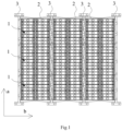
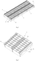
Fig.1 is a schematic diagram of a structure of a battery module provided in an embodiment of the present disclosure; -
Fig.2 is a schematic diagram of structures of a battery unit and end plates provided in the embodiment of the present disclosure; -
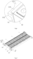
Fig.3 is a schematic diagram of a structure of a unit module provided in the embodiment of the present disclosure; -
Fig.4 is a partial enlarged view of part A inFig.3 ; -
Fig.5 is a schematic diagram of a partial structure of the battery module provided in the embodiment of the present disclosure; -
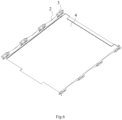
Fig.6 is a schematic diagram of a bottom structure of the battery module provided in the embodiment of the present disclosure. - In the drawings:
- 1: unit module; 11: connecting arm; 111: connecting ear; 112: connecting lip; 113: bending edge; 12: battery cell;
- 2: end plate;
- 3: connecting piece; 31: rod portion; 32: limiting portion; 321: end plate connecting hole; 33: connecting protrusion; 331: connecting hole;
- 4: liquid cooling plate.
- In the description of this disclosure, unless otherwise expressly specified and defined, the terms "connected", "connecting" and "fixed" should be understood in a broad sense. For example, they can be fixed connections, detachable connections, or integrated connections; they can be mechanical or electrical connections; they can be direct connections or indirect connections via an intervening medium; and they can represent internal communication of two components or an interaction relationship between two components. Those of ordinary skill in the art can understand the specific meanings of the above terms in this disclosure based on specific circumstances.
- In this disclosure, unless otherwise expressly specified and defined, a first feature being "on" or "under" a second feature may include direct contact between the first and second features, or contact between them via another intervening feature rather than the direct contact. Moreover, the first feature "on", "above" and "over" the second feature includes the first feature directly above and obliquely above the second feature, or simply means that the level of the first feature is higher than that of the second feature. The first feature "below", "beneath" and "under" the second feature includes the first feature directly below and obliquely below the second feature, or simply means that the level of the first feature is lower than that of the second feature.
- The technical solution of the present invention will be explained below in conjunction with the accompanying drawings and through a specific embodiment.
- This embodiment provides a battery module. As shown in
Figs. 1-6 , the battery module includes a battery unit, connectingpieces 3 andend plates 2. The battery unit includes a plurality ofunit modules 1 arranged along a first direction, and each of theunit modules 1 includes a mounting bracket and a battery cell assembly fixed to the mounting bracket and including a plurality ofbattery cells 12 arranged along the first direction. The connectingpieces 3 extend along the first direction, and are provided on both sides of the battery unit along a second direction perpendicular to the first direction, and the mounting bracket is connected to the connectingpieces 3. The battery unit is provided with theend plates 2 on both ends thereof along the first direction, and both ends of theend plate 2 are connected to two of the connectingpieces 3, respectively. That is to say, the twoend plates 2 and the two connectingpieces 3 can be enclosed to form a frame-like structure, in which the battery unit is placed. In this embodiment, both the first and second directions are horizontal directions. Moreover, the battery unit includes threeunit modules 1. - The battery module provided in this embodiment includes the battery unit, the connecting
pieces 3 and theend plates 2. The battery unit includes the plurality of independently providedunit modules 1, so that thebattery cells 12 first form the plurality ofunit modules 1, and then the plurality ofunit modules 1 form the battery unit. Theunit module 1 contains a smaller number ofbattery cells 12, and thus has a smaller size, which facilitates the production, processing and maintenance. Moreover, when the battery cell(s) 12 in one of theunit modules 1 fails, only thisunit module 1 needs to be replaced, which avoids direct replacement of the battery unit, and thus reduces the cost of maintenance and replacement. Theend plates 2 and the connectingpieces 3 are enclosed to form the frame-like structure for housing the battery unit. The battery unit is placed in the frame-like structure, and the mounting bracket is connected to the connectingpieces 3 so that the connectingpieces 3 have the function of fixing theunit module 1, and theend plates 2 can limit the deformation of thebattery cell 12 when thebattery cell 12 undergoes expansion deformation or explosion, which reduces the possibility of failure ofother battery cells 12 due to compression, and thus improves the durability and service life. - For ease of understanding, the first and second directions are identified in
Fig.1 . InFig.1 , a positive or negative direction of direction a is defined as the first direction, and a positive or negative direction of direction b is defined as the second direction. - In this embodiment, as shown in
Figs. 3 and4 , the mounting bracket includes two connectingarms 11, which are separated along the second direction, and which are correspondingly connected to two of the connectingpieces 3 on both sides of the battery unit. That is, theunit module 1 is simultaneously connected to the connectingpieces 3 on both sides, which ensures the reliability of connection between theunit module 1 and the connectingpieces 3. For example, the connectingarm 11 extends along the first direction, and at least one side of eachbattery cell 12 along the second direction is connected to the connectingarm 11, and the connectingarm 11 has the same length as the battery cell assembly. That is, ends of the connectingarm 11 are flush with ends of the battery cell assembly. Therefore, when end faces of twoadjacent unit modules 1 are fitted together, thebattery cells 12 of the twounit modules 1 are fitted to each other, which reduces the volume of the battery module and increases the energy density. In addition, theend plates 2 are also fitted to the ends of theunit module 1. - In other embodiments, between the two connecting
arms 11, a supporting and connecting arm may also be connected, which can not only connect the two connectingarms 11, but also support the battery cell assembly. At this point, the mounting bracket is U-shaped, with its opening running through both ends of the mounting bracket in the first direction, and the battery cell assembly is placed in the opening. The connectingarms 11 are provided with connectingears 111 protruding on their sides facing away from each other, and the connectingears 111 are connected to the connectingpieces 3. - Each of the connecting
arms 11 is provided with a plurality of connectingears 111, and in this embodiment, each of the connectingarms 11 is provided with a connectinglip 112 protruding on its side facing away from the other connectingarm 11. The connectinglip 112 extends along the first direction, and three connectingears 111 are provided protruding on the connectinglip 112. - For example, a top cover of the
battery cell 12 is arranged to face upwards, and both poles of thebattery cell 12 are placed on the top cover. As shown inFig.4 , a side of the connectingarm 11 facing thebattery cell 12 is provided with a foldededge 113, and a bottom surface of the foldededge 113 is fitted to the top cover of thebattery cell 12, which can limit the position of thebattery cell 12. - In this embodiment, two battery cell assemblies are provided within one
unit module 1 and are arranged along the second direction, and each of the battery cell assemblies includes eight or tenbattery cells 12 arranged along the first direction, and there is a separator between the two battery cell assemblies. In other embodiments, the numbers of the battery cell assemblies within eachunit module 1 and the numbers of thebattery cells 12 within the battery cell assembly can be adjusted adaptively, and are not limited thereto. - For example, as shown in
Fig.5 , the connectingpiece 3 includes arod portion 31 extending along the first direction, and limiting portions provided at both ends of therod portion 31. The battery unit is provided with therod portions 31 on both sides along the second direction, and the mounting bracket is connected to therod portions 31. For example, the connectingears 111 are connected to therod portions 31. The limitingportion 32 protrudes along the second direction from a side of therod portion 31 facing theend plate 2, and a protruding portion of the limitingportion 32 is connected to theend plate 2. With the above structural arrangement, when thebattery cell 12 undergoes expansion deformation, the limitingportions 32 can limit the deformation of theend plates 2, which ensures the stability of the frame-like structure and thus limits the deformation of thebattery cell 12, reducing the possibility of failure ofother battery cells 12 due to compression, and thus improving the durability and service life. In this embodiment, the protruding portion of the limitingportion 32 and the battery unit are placed on both sides of theend plate 2, respectively, and the protruding portion of the limitingportion 32 is fitted with theend plate 2. In other embodiments, the protruding portion of the limitingportion 32 is connected to an end of theend plate 2 facing the connectingpiece 3, and the limitingportion 32 is integrated with theend plate 2. - In this embodiment, the connecting
ear 111 is provided with a through hole which is open in a vertical direction, and is arranged above therod portion 31 and is connected to therod portion 31 through a bolt. - In this embodiment, the limiting
portion 32 is in the shape of a plate arranged vertically, and is perpendicularly connected to therod portion 31. The limitingportion 32 is provided with an endplate connecting hole 321 which is open in the first direction, so that the limitingportion 32 can be connected to theend plate 2 through a bolt. The limitingportions 32 of the connectingpieces 3 on both sides of the same battery unit are each provided in a protruding manner. That is, both sides of theend plate 2 are connected to the limitingportions 32 of two connectingpieces 3, respectively, which ensures the stability of the frame-like structure. - For example, as shown in
Fig.5 , the connectingpiece 3 further includes a connectingprotrusion 33 which is placed on a side of the limitingportion 32 facing away from therod portion 31, and which is provided with a connectinghole 331. The connectinghole 331 is provided so that the connectingpiece 3 can be connected to a case body of a battery pack, a vehicle body or other external structures through a bolt, which improves the practicability. In this embodiment, the connectingprotrusion 33 is block-shaped and protrudes from the limitingportion 32, and the connectinghole 331 is a through hole and is opened in a vertical direction. In other embodiments, the shape of the connectingprotrusion 33 and the position of the connectinghole 331 can be adjusted adaptively, and are not limited herein. - For example, the
rod portion 31, the limitingportions 32, and the connectingprotrusion 33 of the connectingpiece 3 are made of metal, and are provided as an integrated structure, which facilitates the production and processing. In other embodiments, therod portion 31, the limitingportion 32 and the connectingprotrusion 33 can be connected by welding, which is not limited herein. - For example, the
end plate 2 extends along the second direction, and has a plate thickness increasing from the middle towards both sides along the second direction. When thebattery cell 12 undergoes expansion deformation, the middle of theend plate 12 has a larger amount of deformation due to its lower rigidity, while thicker parts on the two sides of theend plate 2 have smaller amounts of deformation due to their connection to the limitingportions 32 and higher rigidity, which ensures the reliability of connection between theend plates 2 and the connectingpieces 3 and thus the stability of the frame-like structure. In this embodiment, a side of theend plate 2 facing away from the unit module is an arc-shaped surface, which facilitates the processing. In addition, theend plate 2 provided in this way has a relatively light weight, which is conducive to the improvement of the energy density of the battery module. - For example, there is a plurality of the battery units provided along the second direction and alternately arranged with the connecting
pieces 3; and on the connectingpiece 3 between two adjacent ones of the battery units, both ends of the limitingportion 32 along the second direction protrude on both sides of therod portion 31, and are connected to two of theend plates 2, respectively. This structural arrangement allows the same connectingpiece 3 to be connected to twoend plates 2, which facilitates the connection of two frame-like structures, thus making it easy to connect two battery units, increasing the number of thebattery cells 12 within the battery module, and improving the practicability of the battery module. This structural arrangement also reduces the number of the connectingpieces 3 between the two battery units, thereby reducing the number of the battery module structures and lowering the cost. This structural arrangement further reduces the weight of the battery module, increases the energy density, and improves the practicability of the battery module. For example, on the connectingpiece 3 between two battery units, the limitingportion 32 is arranged with both ends along the second direction protruding from therod portion 31, such that ends of the connectingpiece 3 form a "T" shape, and the two ends of the limitingportion 32 are connected to twoend plates 2, respectively, reducing the number of the connectingpieces 3 and the spacing between two adjacent battery units, and thus improving the energy density of the battery. - In some embodiments, on two connecting
pieces 3 on both sides of the plurality of battery units, the limitingportions 32 protrude from the rod portions 21 only towards the sides of theend plates 2, thus making ends of the connectingpiece 3 have an "L" shape. - For example, as shown in
Fig.6 , the battery module further includes aliquid cooling plate 4, which can seal the above-mentioned frame-like structure and carry the battery unit. The connectingpieces 3 are connected to theliquid cooling plate 4. Theliquid cooling plate 4 is provided to carry the battery unit, which improves the structural stability of the battery module. In addition, providing the mounting bracket as two disconnected connectingarms 11 also improves the heat transfer efficiency between thebattery cells 12 and theliquid cooling plate 4. For example, theliquid cooling plate 4 is horizontally arranged and placed at the bottoms of the battery unit and the connectingpieces 3, and the two ends of the connectingpiece 3 protrude from an edge of theliquid cooling plate 4 and are connected to theend plates 2. The connectingpieces 3 can be connected to theliquid cooling plate 4 through bolts. The structure of theliquid cooling plate 4 belongs to a related technology, and will not be repeated here. - In other embodiments, the
end plates 2 can be placed above theliquid cooling plate 4, and theend plates 2 are connected to theliquid cooling plate 4 through bolts, improving the stability of the frame-like structure. - In some embodiments, a heat conducting layer is provided between the
liquid cooling plate 4 and theunit module 1, which improves the heat transfer efficiency between thebattery cells 12 and theliquid cooling plate 4, enhances the heat dissipation efficiency of thebattery cells 12, and ensures the safety of the battery module. Furthermore, the heat conducting layer does not have a bonding function, making it easy to detach theunit module 1 from the battery module, which is conducive to the maintenance. - In some other embodiments, a bonding layer is provided between the
liquid cooling plate 4 and theunit module 1, which improves the structural stability and structural strength of the battery module. For example, a heat-conducting silicone layer is provided between theliquid cooling plate 4 and theunit module 1, which has both heat conducting and bonding functions. - This embodiment further provides a vehicle. For example, the above vehicle includes the battery module as described above, which reduces the production cost of the battery module and also lowers the cost of maintenance and replacement.
- The vehicle can be represented in the form of universal terminals. In addition to the battery module as described above, the components of the vehicle can include but are not limited to: the vehicle body, one or more processors, storage devices, and a bus connecting different system components (including the storage devices and the processor(s)).
Claims (10)
- A battery module, comprising:a battery unit, comprising a plurality of unit modules (1) arranged along a first direction, each of the unit modules (1) comprising a mounting bracket and a battery cell assembly fixed to the mounting bracket and comprising a plurality of battery cells (12) arranged along the first direction;connecting pieces (3) extending along the first direction, the connecting pieces (3) being provided on both sides of the battery unit along a second direction perpendicular to the first direction, the mounting bracket being connected to the connecting pieces (3);end plates (2), provided on both ends of the battery unit along the first direction, both ends of the end plate (2) being connected to two of the connecting pieces (3), respectively.
- The battery module according to claim 1, wherein the connecting piece (3) comprises a rod portion (31) extending along the first direction, and limiting portions (32) provided at both ends of the rod portion (31), and the mounting bracket is connected to the rod portion (31), the limiting portion (32) protrudes along the second direction from a side of the rod portion (31) facing the end plate (2), and a protruding portion of the limiting portion (32) is connected to the end plate (2).
- The battery module according to claim 2, wherein the connecting piece (3) further comprises a connecting protrusion (33), which is placed on a side of the limiting portion (32) facing away from the rod portion (31), and which is provided with a connecting hole (331).
- The battery module according to claim 2, wherein there is a plurality of the battery units provided along the second direction and alternately arranged with the connecting pieces (3); and on the connecting piece (3) between two adjacent ones of the battery units, the limiting portion (32) is connected to two of the end plates (2).
- The battery module according to claim 1, wherein the mounting bracket comprises two connecting arms (11), which are separated along the second direction, and which are correspondingly connected to two of the connecting pieces (3).
- The battery module according to claim 1, further comprising a liquid cooling plate (4) which can carry the battery unit, the connecting pieces (3) being connected to the liquid cooling plate (4).
- The battery module according to claim 6, wherein a heat conducting layer is provided between the liquid cooling plate (4) and the unit module (1).
- The battery module according to claim 6, wherein a bonding layer is provided between the liquid cooling plate (4) and the unit module (1).
- The battery module according to any one of claim 1 to 8, wherein the end plate (2) has a plate thickness increasing from the middle towards both sides along the second direction.
- A vehicle, comprising the battery module as claimed in any one of claims 1 to 9.
Applications Claiming Priority (2)
| Application Number | Priority Date | Filing Date | Title |
|---|---|---|---|
| CN202122221448.4U CN215771343U (en) | 2021-09-14 | 2021-09-14 | Battery module and vehicle |
| PCT/CN2022/118804 WO2023040913A1 (en) | 2021-09-14 | 2022-09-14 | Battery module and vehicle |
Publications (2)
| Publication Number | Publication Date |
|---|---|
| EP4404346A1 true EP4404346A1 (en) | 2024-07-24 |
| EP4404346A4 EP4404346A4 (en) | 2025-01-15 |
Family
ID=80087637
Family Applications (1)
| Application Number | Title | Priority Date | Filing Date |
|---|---|---|---|
| EP22869282.8A Pending EP4404346A4 (en) | 2021-09-14 | 2022-09-14 | BATTERY MODULE AND VEHICLE |
Country Status (3)
| Country | Link |
|---|---|
| EP (1) | EP4404346A4 (en) |
| CN (1) | CN215771343U (en) |
| WO (1) | WO2023040913A1 (en) |
Families Citing this family (3)
| Publication number | Priority date | Publication date | Assignee | Title |
|---|---|---|---|---|
| CN215771343U (en) * | 2021-09-14 | 2022-02-08 | 蜂巢能源科技有限公司 | Battery module and vehicle |
| US20240170785A1 (en) * | 2022-11-23 | 2024-05-23 | Ford Global Technologies, Llc | Structural assembly for battery structure of electric vehicle |
| WO2025213416A1 (en) * | 2024-04-11 | 2025-10-16 | 宁德时代新能源科技股份有限公司 | Battery pack, electric device, and energy storage device |
Family Cites Families (7)
| Publication number | Priority date | Publication date | Assignee | Title |
|---|---|---|---|---|
| CN206558575U (en) * | 2017-02-13 | 2017-10-13 | 深圳市沃特玛电池有限公司 | A kind of fixed structure of battery modules |
| KR102270234B1 (en) * | 2017-12-12 | 2021-06-25 | 주식회사 엘지에너지솔루션 | Battery module embedding cross beam and Battery pack comprising the battery module |
| CN208444873U (en) * | 2018-05-18 | 2019-01-29 | 长城汽车股份有限公司 | Battery module and battery pack having the same |
| CN210897429U (en) * | 2019-12-30 | 2020-06-30 | 蜂巢能源科技有限公司 | Power battery pack |
| CN212810401U (en) * | 2020-06-09 | 2021-03-26 | 比亚迪股份有限公司 | Vehicle and battery module thereof |
| CN213366723U (en) * | 2020-09-08 | 2021-06-04 | 恒大新能源技术(深圳)有限公司 | Battery module assembly, battery module and battery system |
| CN215771343U (en) * | 2021-09-14 | 2022-02-08 | 蜂巢能源科技有限公司 | Battery module and vehicle |
-
2021
- 2021-09-14 CN CN202122221448.4U patent/CN215771343U/en active Active
-
2022
- 2022-09-14 WO PCT/CN2022/118804 patent/WO2023040913A1/en not_active Ceased
- 2022-09-14 EP EP22869282.8A patent/EP4404346A4/en active Pending
Also Published As
| Publication number | Publication date |
|---|---|
| CN215771343U (en) | 2022-02-08 |
| EP4404346A4 (en) | 2025-01-15 |
| WO2023040913A1 (en) | 2023-03-23 |
Similar Documents
| Publication | Publication Date | Title |
|---|---|---|
| US11515593B2 (en) | Battery module and battery pack including the same | |
| US11264669B2 (en) | Battery box and battery module | |
| JP2023162215A (en) | Power battery pack and electric vehicle | |
| JP2023503414A (en) | Battery packs and electric vehicles | |
| EP3772124B1 (en) | Battery module and battery pack including the same | |
| JP2026063093A (en) | Battery packs and electric vehicles | |
| WO2023040913A1 (en) | Battery module and vehicle | |
| CN213366696U (en) | Battery module assembly, battery module and battery system | |
| CN214043892U (en) | A battery module, battery pack and battery | |
| CN218568968U (en) | Liquid cooling integration energy memory | |
| WO2024032641A1 (en) | Battery module and battery pack | |
| CN215771342U (en) | Battery pack | |
| CN220138623U (en) | Energy storage module and power supply | |
| WO2025167126A1 (en) | Battery pack and vehicle | |
| CN218586230U (en) | Battery module, battery package and consumer | |
| CN213366723U (en) | Battery module assembly, battery module and battery system | |
| CN115411421A (en) | Battery module, battery package and consumer | |
| CN218887417U (en) | Battery module and battery pack | |
| EP4092812A1 (en) | Battery pack and electric vehicle | |
| CN218677421U (en) | Big module box structure and electricity core module | |
| CN217788623U (en) | Battery pack and battery pack | |
| CN209607828U (en) | Lithium battery energy storage module and lithium battery energy storage module | |
| CN223039059U (en) | A battery module and a battery pack | |
| CN219246773U (en) | Integrated liquid-cooled battery module | |
| CN223927518U (en) | Novel soft packet of electric core module and battery package |
Legal Events
| Date | Code | Title | Description |
|---|---|---|---|
| STAA | Information on the status of an ep patent application or granted ep patent |
Free format text: STATUS: THE INTERNATIONAL PUBLICATION HAS BEEN MADE |
|
| PUAI | Public reference made under article 153(3) epc to a published international application that has entered the european phase |
Free format text: ORIGINAL CODE: 0009012 |
|
| STAA | Information on the status of an ep patent application or granted ep patent |
Free format text: STATUS: REQUEST FOR EXAMINATION WAS MADE |
|
| 17P | Request for examination filed |
Effective date: 20240314 |
|
| AK | Designated contracting states |
Kind code of ref document: A1 Designated state(s): AL AT BE BG CH CY CZ DE DK EE ES FI FR GB GR HR HU IE IS IT LI LT LU LV MC MK MT NL NO PL PT RO RS SE SI SK SM TR |
|
| RIN1 | Information on inventor provided before grant (corrected) |
Inventor name: TANG, LIJUAN Inventor name: ZHANG, HAIJIAN Inventor name: QU, FANDUO |
|
| DAV | Request for validation of the european patent (deleted) | ||
| DAX | Request for extension of the european patent (deleted) | ||
| A4 | Supplementary search report drawn up and despatched |
Effective date: 20241216 |
|
| RIC1 | Information provided on ipc code assigned before grant |
Ipc: H01M 10/613 20140101ALI20241210BHEP Ipc: H01M 10/625 20140101ALI20241210BHEP Ipc: H01M 10/647 20140101ALI20241210BHEP Ipc: H01M 10/6554 20140101ALI20241210BHEP Ipc: H01M 10/6556 20140101ALI20241210BHEP Ipc: H01M 50/264 20210101ALI20241210BHEP Ipc: H01M 50/244 20210101ALI20241210BHEP Ipc: H01M 50/249 20210101ALI20241210BHEP Ipc: H01M 50/209 20210101AFI20241210BHEP |