EP4404337A1 - Battery device - Google Patents
Battery device Download PDFInfo
- Publication number
- EP4404337A1 EP4404337A1 EP23864152.6A EP23864152A EP4404337A1 EP 4404337 A1 EP4404337 A1 EP 4404337A1 EP 23864152 A EP23864152 A EP 23864152A EP 4404337 A1 EP4404337 A1 EP 4404337A1
- Authority
- EP
- European Patent Office
- Prior art keywords
- thermally conductive
- battery unit
- battery
- battery device
- stacked
- Prior art date
- Legal status (The legal status is an assumption and is not a legal conclusion. Google has not performed a legal analysis and makes no representation as to the accuracy of the status listed.)
- Pending
Links
Images
Classifications
-
- H—ELECTRICITY
- H01—ELECTRIC ELEMENTS
- H01M—PROCESSES OR MEANS, e.g. BATTERIES, FOR THE DIRECT CONVERSION OF CHEMICAL ENERGY INTO ELECTRICAL ENERGY
- H01M10/00—Secondary cells; Manufacture thereof
- H01M10/60—Heating or cooling; Temperature control
- H01M10/65—Means for temperature control structurally associated with the cells
- H01M10/655—Solid structures for heat exchange or heat conduction
- H01M10/6554—Rods or plates
-
- H—ELECTRICITY
- H01—ELECTRIC ELEMENTS
- H01M—PROCESSES OR MEANS, e.g. BATTERIES, FOR THE DIRECT CONVERSION OF CHEMICAL ENERGY INTO ELECTRICAL ENERGY
- H01M10/00—Secondary cells; Manufacture thereof
- H01M10/60—Heating or cooling; Temperature control
- H01M10/64—Heating or cooling; Temperature control characterised by the shape of the cells
- H01M10/647—Prismatic or flat cells, e.g. pouch cells
-
- H—ELECTRICITY
- H01—ELECTRIC ELEMENTS
- H01M—PROCESSES OR MEANS, e.g. BATTERIES, FOR THE DIRECT CONVERSION OF CHEMICAL ENERGY INTO ELECTRICAL ENERGY
- H01M10/00—Secondary cells; Manufacture thereof
- H01M10/60—Heating or cooling; Temperature control
- H01M10/61—Types of temperature control
- H01M10/613—Cooling or keeping cold
-
- H—ELECTRICITY
- H01—ELECTRIC ELEMENTS
- H01M—PROCESSES OR MEANS, e.g. BATTERIES, FOR THE DIRECT CONVERSION OF CHEMICAL ENERGY INTO ELECTRICAL ENERGY
- H01M10/00—Secondary cells; Manufacture thereof
- H01M10/60—Heating or cooling; Temperature control
- H01M10/62—Heating or cooling; Temperature control specially adapted for specific applications
- H01M10/623—Portable devices, e.g. mobile telephones, cameras or pacemakers
-
- H—ELECTRICITY
- H01—ELECTRIC ELEMENTS
- H01M—PROCESSES OR MEANS, e.g. BATTERIES, FOR THE DIRECT CONVERSION OF CHEMICAL ENERGY INTO ELECTRICAL ENERGY
- H01M10/00—Secondary cells; Manufacture thereof
- H01M10/60—Heating or cooling; Temperature control
- H01M10/65—Means for temperature control structurally associated with the cells
- H01M10/651—Means for temperature control structurally associated with the cells characterised by parameters specified by a numeric value or mathematical formula, e.g. ratios, sizes or concentrations
-
- H—ELECTRICITY
- H01—ELECTRIC ELEMENTS
- H01M—PROCESSES OR MEANS, e.g. BATTERIES, FOR THE DIRECT CONVERSION OF CHEMICAL ENERGY INTO ELECTRICAL ENERGY
- H01M10/00—Secondary cells; Manufacture thereof
- H01M10/60—Heating or cooling; Temperature control
- H01M10/65—Means for temperature control structurally associated with the cells
- H01M10/653—Means for temperature control structurally associated with the cells characterised by electrically insulating or thermally conductive materials
-
- H—ELECTRICITY
- H01—ELECTRIC ELEMENTS
- H01M—PROCESSES OR MEANS, e.g. BATTERIES, FOR THE DIRECT CONVERSION OF CHEMICAL ENERGY INTO ELECTRICAL ENERGY
- H01M50/00—Constructional details or processes of manufacture of the non-active parts of electrochemical cells other than fuel cells, e.g. hybrid cells
- H01M50/20—Mountings; Secondary casings or frames; Racks, modules or packs; Suspension devices; Shock absorbers; Transport or carrying devices; Holders
- H01M50/204—Racks, modules or packs for multiple batteries or multiple cells
- H01M50/207—Racks, modules or packs for multiple batteries or multiple cells characterised by their shape
- H01M50/209—Racks, modules or packs for multiple batteries or multiple cells characterised by their shape adapted for prismatic or rectangular cells
-
- H—ELECTRICITY
- H01—ELECTRIC ELEMENTS
- H01M—PROCESSES OR MEANS, e.g. BATTERIES, FOR THE DIRECT CONVERSION OF CHEMICAL ENERGY INTO ELECTRICAL ENERGY
- H01M50/00—Constructional details or processes of manufacture of the non-active parts of electrochemical cells other than fuel cells, e.g. hybrid cells
- H01M50/20—Mountings; Secondary casings or frames; Racks, modules or packs; Suspension devices; Shock absorbers; Transport or carrying devices; Holders
- H01M50/289—Mountings; Secondary casings or frames; Racks, modules or packs; Suspension devices; Shock absorbers; Transport or carrying devices; Holders characterised by spacing elements or positioning means within frames, racks or packs
- H01M50/293—Mountings; Secondary casings or frames; Racks, modules or packs; Suspension devices; Shock absorbers; Transport or carrying devices; Holders characterised by spacing elements or positioning means within frames, racks or packs characterised by the material
-
- H—ELECTRICITY
- H01—ELECTRIC ELEMENTS
- H01M—PROCESSES OR MEANS, e.g. BATTERIES, FOR THE DIRECT CONVERSION OF CHEMICAL ENERGY INTO ELECTRICAL ENERGY
- H01M6/00—Primary cells; Manufacture thereof
- H01M6/50—Methods or arrangements for servicing or maintenance, e.g. for maintaining operating temperature
- H01M6/5038—Heating or cooling of cells or batteries
-
- H—ELECTRICITY
- H01—ELECTRIC ELEMENTS
- H01M—PROCESSES OR MEANS, e.g. BATTERIES, FOR THE DIRECT CONVERSION OF CHEMICAL ENERGY INTO ELECTRICAL ENERGY
- H01M2220/00—Batteries for particular applications
- H01M2220/30—Batteries in portable systems, e.g. mobile phone, laptop
-
- Y—GENERAL TAGGING OF NEW TECHNOLOGICAL DEVELOPMENTS; GENERAL TAGGING OF CROSS-SECTIONAL TECHNOLOGIES SPANNING OVER SEVERAL SECTIONS OF THE IPC; TECHNICAL SUBJECTS COVERED BY FORMER USPC CROSS-REFERENCE ART COLLECTIONS [XRACs] AND DIGESTS
- Y02—TECHNOLOGIES OR APPLICATIONS FOR MITIGATION OR ADAPTATION AGAINST CLIMATE CHANGE
- Y02E—REDUCTION OF GREENHOUSE GAS [GHG] EMISSIONS, RELATED TO ENERGY GENERATION, TRANSMISSION OR DISTRIBUTION
- Y02E60/00—Enabling technologies; Technologies with a potential or indirect contribution to GHG emissions mitigation
- Y02E60/10—Energy storage using batteries
Definitions
- the present disclosure relates to an electronic component, more particularly, to a battery device.
- the present application claims priority to Korean Patent Application No. 10-2022-0160261 filed on November 25, 2022 in the Republic of Korea, the disclosures of which are incorporated herein by reference.
- Portable electronic products may provide the required power by including a battery device.
- battery devices generate heat during operation, which affects the efficacy of the electronic products. Therefore, an effective method for improving the heat dissipation efficiency of battery devices is emerging as a challenge to be solved.
- the present disclosure is directed to providing a battery device with excellent heat dissipation effect.
- a battery device comprising: one stacked battery unit having two surfaces facing each other; two support frames provided on the surfaces of the stacked battery unit, respectively, to partially expose the surfaces; two thermally conductive adhesive layers respectively provided on the surfaces of the stacked battery unit exposed by the support frames; and two thermally conductive plates respectively provided on the support frames and respectively fixed on the stacked battery unit through the thermally conductive adhesive layers.
- the stacked battery unit may include a first battery unit; a second battery unit; and a support layer provided between the first battery unit and the second battery unit.
- the first battery unit and the second battery unit may include a soft pack battery cell, respectively.
- the material of the support layer may include plastic.
- each support frame may include plastic.
- each of the thermally conductive adhesive layers may have a thickness in the range of 0.125 mm to 0.5 mm.
- the thermal conductivity of each thermally conductive plate may be greater than the thermal conductivity of each thermally conductive adhesive layer.
- the material of each thermally conductive plate may include stainless steel.
- each of the thermally conductive plates may have a thickness in the range of 0.05 mm to 0.2 mm.
- the battery device may further comprise two printing layers respectively provided on the thermally conductive plates to cover the thermally conductive plates.
- the thermally conductive plate is fixed on the stacked battery unit through a thermally conductive adhesive layer, which corresponds to the surface of the stacked battery unit to increase the heat dissipation area of the stacked battery unit and is advantageous for heat dissipation of the stacked battery unit.
- the stacked battery unit provides a good thermal conduction path through the thermally conductive adhesive layer and the thermally conductive plate, so that the temperature of the stacked battery unit is balanced and has desirable thermal stability. Therefore, the battery device according to the present disclosure has a desirable heat dissipation effect and allows the stacked battery unit to have desirable thermal stability.
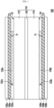
- FIG. 1 is a diagram showing a battery device according to an embodiment of the present disclosure.
- FIG. 1 is a diagram showing a battery device according to an embodiment of the present disclosure.
- a battery device 100 includes one stacked battery unit 110, two support frames 120a and 120b, two thermally conductive adhesive layers 130a and 130b, and two thermally conductive plates 140a and 140b.
- the stacked battery unit 110 has two surfaces S1 and S2 facing each other.
- the support frames 120a and 120b are located on the surfaces S1 and S2 of the stacked battery unit 110, respectively, and partially expose the surfaces S1 and S2, respectively.
- the thermally conductive adhesive layers 130a and 130b are respectively provided on the surfaces S1 and S2 of the stacked battery unit 110 exposed by the support frames 120a and 120b.
- the thermally conductive plates 140a and 140b are provided on the support frames 120a and 120b, respectively, and are fixed on the stacked battery unit 110 through the thermally conductive adhesive layers 130a and 130b, respectively.
- the battery device 100 is a battery device used in a notebook computer or other electronic products, but is not limited thereto.
- the stacked battery unit 110 includes a first battery unit 112, a second battery unit 114, and a support layer 116, among which the support layer 116 is provided between the first battery unit 112 and the second battery unit 114.
- each of the first battery unit 112 and the second battery unit 114 may be a soft pack battery cell.
- the material of the support layer 116 may be plastic, for example, polycarbonate (PC), but is not limited thereto.
- the thickness of the support layer 116 may be 0.2 mm, but is not limited thereto.
- the support frames 120a and 120b include openings 122a and 122b, respectively, and the material of each of the support frames 120a and 120b is plastic, such as polycarbonate, but is not limited thereto. In one embodiment, the thickness of each of the support frames 120a and 120b is 0.2 mm, but is not limited thereto.
- the thermally conductive adhesive layers 130a and 130b in this embodiment are provided in the openings 122a and 122b of the support frames 120a and 120b, respectively, and directly contact the surfaces S1 and S2 of the stacked battery unit 110 exposed by the support frames 120a and 120b.
- the thickness T1 of each of the thermally conductive adhesive layers 130a and 130b is in the range of, for example, 0.125 mm to 0.5 mm.
- the thermally conductive adhesive layers 130a and 130b may be, for example, 3M adhesives having a thermal conductivity of 0.6 W/mK, such as 3M TM 8805 (0.125 mm thickness), 3M TM 8810 (0.25 mm thickness), 3M TM 8815 (0.375 mm thickness), or 3M TM 8820 (0.5mm thickness) module, but is not limited thereto.
- the thermally conductive adhesive layers 130a and 130b fill the openings 122a and 122b of the support frames 120a and 120b and are cut to coincide with the openings 122a and 122b.
- the thermally conductive adhesive layers 130a and 130b may fill the openings 122a and 122b of the support frames 120a and 120b and extend onto the support frames 120a and 120b.
- the thermally conductive plates 140a and 140b according to this embodiment are specifically flat, and the thermal conductivity of each of the thermally conductive plates 140a and 140b is greater than the thermal conductivity of each of the thermally conductive adhesive layers 130a and 130b.
- the material of each of the thermally conductive plates 140a and 140b may be stainless steel, for example, stainless steel 304 or stainless steel 316, and the thermal conductivity of stainless steel 304 and stainless steel 316 is 16.3 W/m°C, respectively.
- the thickness T2 of each of the thermally conductive plates 140a and 140b is in the range of 0.05 mm to 0.2 mm.
- the thickness T2 is preferably 0.1 mm, and when the thermally conductive plates 140a and 140b are made of stainless steel 316, the thickness T2 is preferably 0.15 mm.
- the battery device 100 also includes two printing layers 150a and 150b, and the printing layers 150a and 150b are provided on the thermally conductive plates 140a and 140b, respectively, to cover the thermally conductive plates 140a and 140b.
- the printing layers 150a and 150b may include text or image, and display information such as a model of the battery device 100. Accordingly, the printing layers 150a and 150b may also be referred to as label layers.
- the thickness of the printing layers 150a and 150b is 0.1 mm, for example.
- the thermally conductive plate is fixed on the stacked battery unit through a thermally conductive adhesive layer, which corresponds to the surface of the stacked battery unit and increases the heat dissipation area of the stacked battery unit. Therefore, it is advantageous for heat dissipation of the stacked battery unit.
- the stacked battery unit also provides a good thermal conduction path through the thermally conductive adhesive layer and the thermally conductive plate so that the temperature of the stacked battery unit is balanced to have desirable thermal stability. Therefore, the battery device according to the present disclosure has a good heat dissipation effect (temperature drop by at least 3°C) and allows the stacked battery unit to have desirable thermal stability.
Landscapes
- Chemical & Material Sciences (AREA)
- Chemical Kinetics & Catalysis (AREA)
- Electrochemistry (AREA)
- General Chemical & Material Sciences (AREA)
- Engineering & Computer Science (AREA)
- Manufacturing & Machinery (AREA)
- General Physics & Mathematics (AREA)
- Algebra (AREA)
- Physics & Mathematics (AREA)
- Mathematical Analysis (AREA)
- Mathematical Optimization (AREA)
- Pure & Applied Mathematics (AREA)
- Life Sciences & Earth Sciences (AREA)
- Biophysics (AREA)
- Secondary Cells (AREA)
- Battery Mounting, Suspending (AREA)
Abstract
Description
- The present disclosure relates to an electronic component, more particularly, to a battery device. The present application claims priority to
Korean Patent Application No. 10-2022-0160261 filed on November 25, 2022 - Portable electronic products (e.g., notebook computers) may provide the required power by including a battery device. However, battery devices generate heat during operation, which affects the efficacy of the electronic products. Therefore, an effective method for improving the heat dissipation efficiency of battery devices is emerging as a challenge to be solved.
- The present disclosure is directed to providing a battery device with excellent heat dissipation effect.
- In one aspect of the present disclosure, there is provided a battery device, comprising: one stacked battery unit having two surfaces facing each other; two support frames provided on the surfaces of the stacked battery unit, respectively, to partially expose the surfaces; two thermally conductive adhesive layers respectively provided on the surfaces of the stacked battery unit exposed by the support frames; and two thermally conductive plates respectively provided on the support frames and respectively fixed on the stacked battery unit through the thermally conductive adhesive layers.
- In an embodiment of the present disclosure, the stacked battery unit may include a first battery unit; a second battery unit; and a support layer provided between the first battery unit and the second battery unit.
- In an embodiment of the present disclosure, the first battery unit and the second battery unit may include a soft pack battery cell, respectively.
- In an embodiment of the present disclosure, the material of the support layer may include plastic.
- In an embodiment of the present disclosure, the material of each support frame may include plastic.
- In an embodiment of the present disclosure, each of the thermally conductive adhesive layers may have a thickness in the range of 0.125 mm to 0.5 mm.
- In an embodiment of the present disclosure, the thermal conductivity of each thermally conductive plate may be greater than the thermal conductivity of each thermally conductive adhesive layer.
- In an embodiment of the present disclosure, the material of each thermally conductive plate may include stainless steel.
- In an embodiment of the present disclosure, each of the thermally conductive plates may have a thickness in the range of 0.05 mm to 0.2 mm.
- In an embodiment of the present disclosure, the battery device may further comprise two printing layers respectively provided on the thermally conductive plates to cover the thermally conductive plates.
- As described above, in the battery device according to the present disclosure, the thermally conductive plate is fixed on the stacked battery unit through a thermally conductive adhesive layer, which corresponds to the surface of the stacked battery unit to increase the heat dissipation area of the stacked battery unit and is advantageous for heat dissipation of the stacked battery unit. In addition, the stacked battery unit provides a good thermal conduction path through the thermally conductive adhesive layer and the thermally conductive plate, so that the temperature of the stacked battery unit is balanced and has desirable thermal stability. Therefore, the battery device according to the present disclosure has a desirable heat dissipation effect and allows the stacked battery unit to have desirable thermal stability.
-
FIG. 1 is a diagram showing a battery device according to an embodiment of the present disclosure. - In order to understand the features and advantages of the present disclosure more clearly and easily, a detailed description is provided in conjunction with the drawings through the following embodiment.
- The present disclosure can be understood by referring to the following detailed description and the accompanying drawings, and it should be noted that for easy understanding of the present disclosure and conciseness of the drawings, the structures in the drawings are not drawn to scale. In addition, the quantity and size of each component in the drawing is only an example and does not limit the present disclosure.
-
FIG. 1 is a diagram showing a battery device according to an embodiment of the present disclosure. According toFIG. 1 , in this embodiment, abattery device 100 includes one stacked battery unit 110, twosupport frames adhesive layers conductive plates support frames adhesive layers support frames conductive plates support frames adhesive layers - In detail, the
battery device 100 according to this embodiment is a battery device used in a notebook computer or other electronic products, but is not limited thereto. The stacked battery unit 110 includes afirst battery unit 112, asecond battery unit 114, and a support layer 116, among which the support layer 116 is provided between thefirst battery unit 112 and thesecond battery unit 114. In the first embodiment, each of thefirst battery unit 112 and thesecond battery unit 114 may be a soft pack battery cell. In one embodiment, the material of the support layer 116 may be plastic, for example, polycarbonate (PC), but is not limited thereto. In one embodiment, the thickness of the support layer 116 may be 0.2 mm, but is not limited thereto. - Referring to
FIG. 1 again, in this embodiment, thesupport frames openings support frames support frames - In addition, the thermally conductive
adhesive layers openings support frames support frames adhesive layers adhesive layers adhesive layers openings support frames openings adhesive layers openings support frames support frames - In addition, the thermally
conductive plates conductive plates adhesive layers conductive plates conductive plates conductive plates conductive plates - In addition, the
battery device 100 according to this embodiment also includes twoprinting layers printing layers conductive plates conductive plates printing layers battery device 100. Accordingly, theprinting layers printing layers - As described above, in the battery device according to the present disclosure, the thermally conductive plate is fixed on the stacked battery unit through a thermally conductive adhesive layer, which corresponds to the surface of the stacked battery unit and increases the heat dissipation area of the stacked battery unit. Therefore, it is advantageous for heat dissipation of the stacked battery unit. In addition, the stacked battery unit also provides a good thermal conduction path through the thermally conductive adhesive layer and the thermally conductive plate so that the temperature of the stacked battery unit is balanced to have desirable thermal stability. Therefore, the battery device according to the present disclosure has a good heat dissipation effect (temperature drop by at least 3°C) and allows the stacked battery unit to have desirable thermal stability.
- The present disclosure has been described through the embodiment as described above, but is not limited thereto, and appropriate changes and modifications can be made by those skilled in the art within the range that does not deviate from the purpose of the present disclosure, and the scope of protection of the present disclosure shall be based on the appended claims.
-
- 100: battery device
- 110: stacked battery unit
- 112: first battery unit
- 114: second battery unit
- 116: support layer
- 120a, 120b: support frame
- 122a, 122b: opening
- 130a, 130b: thermally conductive adhesive layer
- 140a, 140b: thermally conductive plate
- 150a, 150b: printing layer
- S1, S2: surface
- T1, T2: thickness
Claims (10)
- A battery device, comprising:one stacked battery unit having two surfaces facing each other;two support frames provided on the surfaces of the stacked battery unit, respectively, to partially expose the surfaces;two thermally conductive adhesive layers respectively provided on the surfaces of the stacked battery unit exposed by the support frames; andtwo thermally conductive plates respectively provided on the support frames and respectively fixed on the stacked battery unit through the thermally conductive adhesive layers.
- The battery device according to claim 1,
wherein the stacked battery unit includes:a first battery unit;a second battery unit; anda support layer provided between the first battery unit and the second battery unit. - The battery device according to claim 2,
wherein the first battery unit and the second battery unit include a soft pack battery cell, respectively. - The battery device according to claim 2,
wherein the material of the support layer includes plastic. - The battery device according to claim 1,
wherein the material of each support frame includes plastic. - The battery device according to claim 1,
wherein each of the thermally conductive adhesive layers has a thickness in the range of 0.125 mm to 0.5 mm. - The battery device according to claim 1,
wherein the thermal conductivity of each thermally conductive plate is greater than the thermal conductivity of each thermally conductive adhesive layer. - The battery device according to claim 1,
wherein the material of each thermally conductive plate includes stainless steel. - The battery device according to claim 1,
wherein each of the thermally conductive plates has a thickness in the range of 0.05 mm to 0.2 mm. - The battery device according to claim 1, further comprising:
two printing layers respectively provided on the thermally conductive plates to cover the thermally conductive plates.
Applications Claiming Priority (2)
| Application Number | Priority Date | Filing Date | Title |
|---|---|---|---|
| KR1020220160261A KR102943825B1 (en) | 2022-11-25 | 2022-11-25 | Battery device |
| PCT/KR2023/005563 WO2024111765A1 (en) | 2022-11-25 | 2023-04-24 | Battery device |
Publications (2)
| Publication Number | Publication Date |
|---|---|
| EP4404337A1 true EP4404337A1 (en) | 2024-07-24 |
| EP4404337A4 EP4404337A4 (en) | 2025-07-30 |
Family
ID=90675584
Family Applications (1)
| Application Number | Title | Priority Date | Filing Date |
|---|---|---|---|
| EP23864152.6A Pending EP4404337A4 (en) | 2022-11-25 | 2023-04-24 | BATTERY DEVICE |
Country Status (5)
| Country | Link |
|---|---|
| EP (1) | EP4404337A4 (en) |
| JP (1) | JP7688233B2 (en) |
| KR (1) | KR102943825B1 (en) |
| CN (1) | CN118591929A (en) |
| WO (1) | WO2024111765A1 (en) |
Family Cites Families (7)
| Publication number | Priority date | Publication date | Assignee | Title |
|---|---|---|---|---|
| CN109585904B (en) * | 2017-09-29 | 2021-11-23 | 辉能科技股份有限公司 | Flexible lithium battery |
| KR20190051300A (en) * | 2017-11-06 | 2019-05-15 | 주식회사 엘지화학 | Method of attaching cooling plate to battery module and battery pack manufactured by the same |
| CN113228387B (en) * | 2019-01-25 | 2023-10-27 | 株式会社东芝 | Battery packs and battery systems |
| CN112117400A (en) * | 2019-06-21 | 2020-12-22 | 比亚迪股份有限公司 | Power battery package and vehicle |
| KR102762546B1 (en) * | 2019-11-26 | 2025-02-03 | 주식회사 엘지에너지솔루션 | Battery module |
| KR20220107551A (en) * | 2021-01-25 | 2022-08-02 | 주식회사 엘지에너지솔루션 | Battery module having a cooling plate having excellent rigidity and ESS including the same |
| KR102486723B1 (en) | 2021-05-27 | 2023-01-09 | 조선대학교산학협력단 | Providing method of diagnostic information on alzheimer's disease using extreme learning machine |
-
2022
- 2022-11-25 KR KR1020220160261A patent/KR102943825B1/en active Active
-
2023
- 2023-04-24 WO PCT/KR2023/005563 patent/WO2024111765A1/en not_active Ceased
- 2023-04-24 JP JP2024523967A patent/JP7688233B2/en active Active
- 2023-04-24 CN CN202380015907.2A patent/CN118591929A/en active Pending
- 2023-04-24 EP EP23864152.6A patent/EP4404337A4/en active Pending
Also Published As
| Publication number | Publication date |
|---|---|
| KR102943825B1 (en) | 2026-03-24 |
| KR20240077888A (en) | 2024-06-03 |
| EP4404337A4 (en) | 2025-07-30 |
| WO2024111765A1 (en) | 2024-05-30 |
| JP2024545391A (en) | 2024-12-06 |
| CN118591929A (en) | 2024-09-03 |
| JP7688233B2 (en) | 2025-06-03 |
Similar Documents
| Publication | Publication Date | Title |
|---|---|---|
| US8345420B2 (en) | Battery assembly for battery powered portable devices | |
| CN113658517A (en) | Display module and assembling method thereof, and display device | |
| US20190011760A1 (en) | Display module and display device | |
| EP4682856A1 (en) | Electronic device | |
| CN105759498B (en) | Display device | |
| CN107728380B (en) | Backlight module and display device | |
| US20250377696A1 (en) | Electronic Device | |
| US12262582B2 (en) | Display module having magnetic attraction structure and bonding portions and display device | |
| US20130114290A1 (en) | Display module | |
| KR102030112B1 (en) | Battery pack | |
| JP6850948B2 (en) | Surface light source device, display device, and electronic device | |
| CN104571654A (en) | Touch display panel, touch display device and display device | |
| CN115171534B (en) | Display module and display device | |
| TWI687799B (en) | Heat dissipation module, display device having the same and assembly method thereof | |
| CN108459439B (en) | Backlight modules and liquid crystal display devices | |
| JP7688233B2 (en) | Battery Device | |
| CN105717708A (en) | Backlight module, display module and display device | |
| CN106163230A (en) | Display screen module and mobile terminal | |
| TW202422928A (en) | Battery device | |
| CN111354269A (en) | Display devices and electronic equipment | |
| US20220300048A1 (en) | Thermal management systems for electronic devices and related methods | |
| JP2001313487A (en) | Thermal insulation member for electronic parts and electronic parts | |
| CN1963653A (en) | Electrophoretic display module and electrophoretic display device | |
| JP2004004397A (en) | Reflection type liquid crystal display element | |
| US20260143610A1 (en) | Electronic device |
Legal Events
| Date | Code | Title | Description |
|---|---|---|---|
| STAA | Information on the status of an ep patent application or granted ep patent |
Free format text: STATUS: UNKNOWN |
|
| STAA | Information on the status of an ep patent application or granted ep patent |
Free format text: STATUS: THE INTERNATIONAL PUBLICATION HAS BEEN MADE |
|
| PUAI | Public reference made under article 153(3) epc to a published international application that has entered the european phase |
Free format text: ORIGINAL CODE: 0009012 |
|
| STAA | Information on the status of an ep patent application or granted ep patent |
Free format text: STATUS: REQUEST FOR EXAMINATION WAS MADE |
|
| 17P | Request for examination filed |
Effective date: 20240322 |
|
| AK | Designated contracting states |
Kind code of ref document: A1 Designated state(s): AL AT BE BG CH CY CZ DE DK EE ES FI FR GB GR HR HU IE IS IT LI LT LU LV MC ME MK MT NL NO PL PT RO RS SE SI SK SM TR |
|
| A4 | Supplementary search report drawn up and despatched |
Effective date: 20250626 |
|
| RIC1 | Information provided on ipc code assigned before grant |
Ipc: H01M 10/6554 20140101AFI20250620BHEP Ipc: H01M 10/647 20140101ALI20250620BHEP Ipc: H01M 10/613 20140101ALI20250620BHEP Ipc: H01M 10/623 20140101ALI20250620BHEP Ipc: H01M 10/651 20140101ALI20250620BHEP Ipc: H01M 6/50 20060101ALI20250620BHEP |
|
| DAV | Request for validation of the european patent (deleted) | ||
| DAX | Request for extension of the european patent (deleted) |