EP4404336A1 - Immersion-type power battery thermal management system - Google Patents
Immersion-type power battery thermal management system Download PDFInfo
- Publication number
- EP4404336A1 EP4404336A1 EP23848459.6A EP23848459A EP4404336A1 EP 4404336 A1 EP4404336 A1 EP 4404336A1 EP 23848459 A EP23848459 A EP 23848459A EP 4404336 A1 EP4404336 A1 EP 4404336A1
- Authority
- EP
- European Patent Office
- Prior art keywords
- liquid
- external
- thermal management
- immersion
- management system
- Prior art date
- Legal status (The legal status is an assumption and is not a legal conclusion. Google has not performed a legal analysis and makes no representation as to the accuracy of the status listed.)
- Granted
Links
Images

Classifications
-
- H—ELECTRICITY
- H01—ELECTRIC ELEMENTS
- H01M—PROCESSES OR MEANS, e.g. BATTERIES, FOR THE DIRECT CONVERSION OF CHEMICAL ENERGY INTO ELECTRICAL ENERGY
- H01M10/00—Secondary cells; Manufacture thereof
- H01M10/60—Heating or cooling; Temperature control
- H01M10/61—Types of temperature control
- H01M10/613—Cooling or keeping cold
-
- H—ELECTRICITY
- H01—ELECTRIC ELEMENTS
- H01M—PROCESSES OR MEANS, e.g. BATTERIES, FOR THE DIRECT CONVERSION OF CHEMICAL ENERGY INTO ELECTRICAL ENERGY
- H01M10/00—Secondary cells; Manufacture thereof
- H01M10/60—Heating or cooling; Temperature control
- H01M10/61—Types of temperature control
- H01M10/615—Heating or keeping warm
-
- H—ELECTRICITY
- H01—ELECTRIC ELEMENTS
- H01M—PROCESSES OR MEANS, e.g. BATTERIES, FOR THE DIRECT CONVERSION OF CHEMICAL ENERGY INTO ELECTRICAL ENERGY
- H01M10/00—Secondary cells; Manufacture thereof
- H01M10/60—Heating or cooling; Temperature control
- H01M10/63—Control systems
-
- H—ELECTRICITY
- H01—ELECTRIC ELEMENTS
- H01M—PROCESSES OR MEANS, e.g. BATTERIES, FOR THE DIRECT CONVERSION OF CHEMICAL ENERGY INTO ELECTRICAL ENERGY
- H01M10/00—Secondary cells; Manufacture thereof
- H01M10/60—Heating or cooling; Temperature control
- H01M10/65—Means for temperature control structurally associated with the cells
- H01M10/653—Means for temperature control structurally associated with the cells characterised by electrically insulating or thermally conductive materials
-
- H—ELECTRICITY
- H01—ELECTRIC ELEMENTS
- H01M—PROCESSES OR MEANS, e.g. BATTERIES, FOR THE DIRECT CONVERSION OF CHEMICAL ENERGY INTO ELECTRICAL ENERGY
- H01M10/00—Secondary cells; Manufacture thereof
- H01M10/60—Heating or cooling; Temperature control
- H01M10/65—Means for temperature control structurally associated with the cells
- H01M10/655—Solid structures for heat exchange or heat conduction
- H01M10/6556—Solid parts with flow channel passages or pipes for heat exchange
-
- H—ELECTRICITY
- H01—ELECTRIC ELEMENTS
- H01M—PROCESSES OR MEANS, e.g. BATTERIES, FOR THE DIRECT CONVERSION OF CHEMICAL ENERGY INTO ELECTRICAL ENERGY
- H01M10/00—Secondary cells; Manufacture thereof
- H01M10/60—Heating or cooling; Temperature control
- H01M10/65—Means for temperature control structurally associated with the cells
- H01M10/656—Means for temperature control structurally associated with the cells characterised by the type of heat-exchange fluid
- H01M10/6567—Liquids
- H01M10/6568—Liquids characterised by flow circuits, e.g. loops, located externally to the cells or cell casings
-
- H—ELECTRICITY
- H01—ELECTRIC ELEMENTS
- H01M—PROCESSES OR MEANS, e.g. BATTERIES, FOR THE DIRECT CONVERSION OF CHEMICAL ENERGY INTO ELECTRICAL ENERGY
- H01M50/00—Constructional details or processes of manufacture of the non-active parts of electrochemical cells other than fuel cells, e.g. hybrid cells
- H01M50/20—Mountings; Secondary casings or frames; Racks, modules or packs; Suspension devices; Shock absorbers; Transport or carrying devices; Holders
- H01M50/204—Racks, modules or packs for multiple batteries or multiple cells
-
- H—ELECTRICITY
- H01—ELECTRIC ELEMENTS
- H01M—PROCESSES OR MEANS, e.g. BATTERIES, FOR THE DIRECT CONVERSION OF CHEMICAL ENERGY INTO ELECTRICAL ENERGY
- H01M10/00—Secondary cells; Manufacture thereof
- H01M10/60—Heating or cooling; Temperature control
- H01M10/61—Types of temperature control
- H01M10/617—Types of temperature control for achieving uniformity or desired distribution of temperature
-
- Y—GENERAL TAGGING OF NEW TECHNOLOGICAL DEVELOPMENTS; GENERAL TAGGING OF CROSS-SECTIONAL TECHNOLOGIES SPANNING OVER SEVERAL SECTIONS OF THE IPC; TECHNICAL SUBJECTS COVERED BY FORMER USPC CROSS-REFERENCE ART COLLECTIONS [XRACs] AND DIGESTS
- Y02—TECHNOLOGIES OR APPLICATIONS FOR MITIGATION OR ADAPTATION AGAINST CLIMATE CHANGE
- Y02E—REDUCTION OF GREENHOUSE GAS [GHG] EMISSIONS, RELATED TO ENERGY GENERATION, TRANSMISSION OR DISTRIBUTION
- Y02E60/00—Enabling technologies; Technologies with a potential or indirect contribution to GHG emissions mitigation
- Y02E60/10—Energy storage using batteries
Definitions
- the invention relates to the technical field of thermal management of power batteries, in particular to an immersion-type thermal management system for power batteries.
- the invention provides an immersion-type thermal management system for power batteries, which effectively solves the problem of poor thermal uniformity and safety of the power batteries in use, facilitates efficient and convenient thermal management of the power batteries, and prevents thermal runaway accidents of the power batteries.
- An immersion-type thermal management system for power batteries comprises a power battery unit and a thermal management unit, wherein the power battery unit comprises a box, a battery module and a liquid cooling plate, the box is provided with an external liquid inlet and an external liquid outlet, the liquid cooling plate is provided with internal liquid outlets and located below the battery module, a liquid passage is arranged in the liquid cooling plate, an immersion space is formed in the box, the internal liquid outlets are located between and connected to the liquid passage and the immersion space, the external liquid inlet is connected to the liquid passage, and the external liquid outlet is connected to the immersion space; the thermal management unit comprises a controller and an external circulation path formed outside the box, the external circulation path is connected to the external liquid inlet from the external liquid outlet and comprises an expansion box, a circulating pump, a water cooling unit, a heater and a check valve which are sequentially connected from the external liquid outlet, and the expansion box, the circulating pump, the water cooling unit and the heater are all connected to the controller; liquid enters the liquid passage from the external circulation path via the external liquid in
- the liquid passage comprises a plurality of S-shaped passages which are arranged in parallel, and a plurality of liquid diverter partitions are arranged at the external liquid inlet to allow liquid flowing in via the external liquid inlet to enter the S-shaped passages uniformly.
- the external liquid outlet is formed in an upper portion of the box and located above the battery module.
- a filter is arranged between the expansion box and the circulating pump.
- a first temperature sensor is arranged at the external liquid inlet, connected to the controller and used for monitoring a temperature of the liquid flowing in via the external liquid inlet.
- a second temperature sensor is arranged at the external liquid outlet, connected to the controller and used for monitoring a temperature of the liquid flowing in via the external liquid outlet.
- the system further has a self-circulation mode and a static mode, and the controller controls the system to switch between the cooling mode, the heating mode, the self-circulation mode and the static mode.
- thermally conductive silicone is arranged between the battery module and the liquid cooling plate.
- the box is provided with N external liquid inlets, N is a positive integer, an interior of the liquid cooling plate is divided into N liquid inlet spaces, the external liquid inlets are connected to the liquid inlet spaces in one-to-one correspondence, and the liquid passage is arranged in each liquid inlet space.
- the internal liquid outlets are formed in two ends of the liquid cooling plate.
- the technical solution of the invention has at least the following beneficial effects: the immersion-type thermal management system for power batteries provided by the invention has a heating mode and a cooling mode and can be easily controlled as required, and liquid can sufficiently exchange heat with the battery module, so the efficiency is high, the effect is good, the problem of poor thermal uniformity and safety in use of power batteries is effectively solved, efficient and convenient thermal management of the power batteries is facilitated, and thermal runaway accidents of the power batteries are prevented.
- FIGS. 1 , box; 2, battery module; 3, liquid cooling plate; 4, external liquid inlet; 5, external liquid outlet; 6, liquid passage; 7, immersion space; 8, internal liquid outlet; 9, expansion box; 10, circulating pump; 11, water cooling unit; 12, heater; 13, check valve; 14, flow divider partition; 15, filter; 16, first temperature sensor; 17, second temperature sensor; 18, controller.
- an embodiment of the invention provides an immersion-type thermal management system for power batteries, comprising a power battery unit and a thermal management unit;
- the power battery unit comprises a box 1, a battery module 2 and a liquid cooling plate 3, the box 1 is provided with an external liquid inlet 4 and an external liquid outlet 5, the liquid cooling plate 3 is provided with internal liquid outlets 8 and located below the battery module 2, a liquid passage 6 is arranged in the liquid cooling plate 3, an immersion space 7 is formed in the box 1, the internal liquid outlets 8 are located between and connected to the liquid passage 6 and the immersion space 7, the external liquid inlet 4 is connected to the liquid passage 6, and the external liquid outlet 5 is connected to the immersion space 7;
- the thermal management unit comprises a controller 18 and an external circulation path formed outside the box 1, the external circulation path is connected to the external liquid inlet 4 from the external liquid outlet 5 and comprises an expansion box 9, a circulating pump 10, a water cooling unit 11, a heater 12 and a check valve 13 which are sequentially connected from the external liquid outlet 5, and the expansion
- the liquid passage 6 comprises a plurality of S-shaped passages which are arranged in parallel, a plurality of flow divider partitions 14 are arranged at the external liquid outlet 4 to allow liquid flowing in via the external liquid outlet 4 to uniformly enter the S-shaped passages, the external liquid outlet 5 is formed in an upper portion of the box 1 and located above the battery module 2, and a filter 15 is arranged between the expansion box 9 and the circulating pump 10 and is used for filtering out impurities in the liquid; and a first temperature sensor 16 is arranged at the external liquid inlet 4, connected to the controller 18 and used for monitoring the temperature of the liquid flowing in via the external liquid inlet 4, and a second temperature sensor 17 is arranged at the external liquid outlet 5, connected to the controller 18 and used for monitoring the temperature of the liquid flowing out via the external liquid outlet 5.
- Thermally conductive silicone is arranged between the battery module 2 and the liquid cooling plate 3 to enhance heat transfer between the battery module 2 and the liquid cooling plate 3, the internal liquid outlets 8 are formed in two ends of the liquid cooling plate 3 and are not blocked by the thermally conductive silicone.
- the thermal management system has a self-circulation mode and a static mode, and the controller 18 controls the thermal management system to switch between a cooling mode, a heating mode, the self-circulation mode and the static mode specifically as follows:
- the circulation circuit including the box 1 of the power battery unit is filled with heat-transfer liquid.
- the controller 18 sends a running instruction to the circulating pump 10 and the water cooling unit 11 to enable the circulating pump 10 and the water cooling unit 11 to work.
- heat generated by the battery module 2 will be gradually transferred to the liquid in the power battery unit, and the liquid is driven by the circulating pump 10 to enter the external circulation path via the external liquid outlet 5; because gas will be generated in use of the battery module 2 and will overflow into a cavity in the power battery unit, the heat transfer efficiency of the system and the safety of a power battery in use will be severely affected if the gas cannot be discharged in time; in view of this, the liquid entering the external circulation path first passes through the expansion box 9 to discharge the gas generated, then flows through the filter 15 to filter out impurities in the power battery unit, then flows into the circulating pump 10 to improve the driving force, and then enters the water cooling unit 11 to transfer heat absorbed from the battery module 2 to the water cooling unit 11 to reduce the temperature of the liquid; in this mode, the heater 12 does
- the controller 18 monitors the temperature of the liquid flowing into the power battery unit and the liquid flowing out of the power battery unit through the first temperature sensor 16 and the second temperature sensor 17 respectively to regulate the operating power of the circulating pump 10 and the water cooling unit 11.
- the controller 18 sends a running instruction to the circulating pump 10 and the heater 12 to enable the circulating pump 10 and the heater 12 to work.
- the immersion-type thermal management system runs in the same way as in the cooling mode in other aspects.
- the controller 18 sends a running instruction to the circulating pump 10 to enable the circulating pump to work, and the internal temperature of the power battery unit is uniformized by flowing of liquid. In this mode, neither the water cooling unit nor the heater works.
- the thermal management system In the static mode, the thermal management system is in a static state and does not work.
- liquid overflows from the tops of the S-shaped passages of the liquid cooling plate 3 the battery module 2 is directly immersed in the overflowing liquid, and the liquid in the S-shaped passages of the liquid cooling plate 3 can indirectly exchange heat with the bottom of the battery module 2, thus solving the problem that the heat-exchange uniformity is poor because the bottom of the battery module 2 cannot be immersed and guaranteeing good heat-exchange uniformity of the battery module 2.
- the liquid outlet of the power battery unit is formed in the upper portion of the box 1.
- the liquid outlet is formed in the upper portion of the box 1 to easily discharge the generated gas along with the liquid in the box, thus greatly reducing the risk of thermal safety accidents of the power battery unit.
- the expansion box 9 is arranged in the system circuit and is connected to a position close to the external liquid outlet 5 of the power battery unit, such that gas taken out of the power battery unit by liquid can be quickly and effectively absorbed into the expansion box 9 to be discharged into the atmosphere, thus reducing harm of the gas to the system.
- the water-cooling unit 11 and the heater 12 are arranged in the system circuit, such that the system can both cool and heat a power battery, thus improving the working adaptivity of the power battery in high-temperature and low-temperature harsh conditions.
- a liquid level sensor is arranged in the expansion box 9 and connected to the controller 18 through a signal acquisition line.
- the flow rate of liquid in the system can be properly controlled by changing the liquid level, and a liquid supply signal can be provided, thus facilitating efficient and safe use of the thermal management system.
- the number of the external liquid outlets 4 is two, the interior of the liquid cooling plate 3 is divided into two liquid inlet spaces, and the external liquid outlets 4 are connected to the liquid passages 6 in the liquid inlet spaces in one-to-one correspondence to allow liquid to enter the liquid cooling plate 3 from the external circulation path.
- the number of the external liquid outlets 4 can be designed according to the size of the liquid cooling plate 3, the amount of liquid entering the liquid cooling plate 3, a desired heating/cooling effect and other factors, for example, the number of the external liquid outlets 4 may be 1, 3, 4 or 5.
- the interior of the liquid cooling plate 3 is divided into the same number of liquid inlet spaces, the external liquid outlets 4 are connected to the liquid inlet spaces in one-to-one correspondence, and a liquid passage 6 is arranged in each liquid inlet space.
- the immersion-type thermal management system for power batteries provided by the invention has a heating mode and a cooling mode and can be easily controlled as required, and liquid can sufficiently exchange heat with the battery module, so the efficiency is high, the effect is good, the problem of poor thermal uniformity and safety in use of power batteries is effectively solved, efficient and convenient thermal management of the power batteries is facilitated, and thermal runaway accidents of the power batteries are prevented.
Landscapes
- Engineering & Computer Science (AREA)
- Chemical & Material Sciences (AREA)
- Chemical Kinetics & Catalysis (AREA)
- Electrochemistry (AREA)
- General Chemical & Material Sciences (AREA)
- Manufacturing & Machinery (AREA)
- Automation & Control Theory (AREA)
- Secondary Cells (AREA)
Abstract
Description
- The invention relates to the technical field of thermal management of power batteries, in particular to an immersion-type thermal management system for power batteries.
- In recent years, with the wide use of power batteries, application scenarios of the power batteries become increasingly diversified and complex, accompanied with the gradual emergence of application problems, among which the unsatisfying consistency in electrical performance, short cycle life and short battery life caused by poor temperature uniformity of the power batteries are prominent. In addition, the frequent occurrence of explosions and fires of the power batteries leads to extensive attention to the thermal safety of the power batteries.
- Thermal management systems for batteries in the prior art have at least the following defects:
- 1. The replacement of hot liquid in a closed cavity leads to low heat-exchange efficiency. In the prior art, a sealed battery box is used to allow a heat-exchange liquid medium to flow therein, and heat/cold of a battery is indirectly transferred to the outside by means of a heat-exchange device, thus greatly compromising the heat-exchange efficiency; in addition, the liquid in the sealed battery box has a poor flow characteristic, which makes it impossible to drive a flow field to dissipate heat uniformly, so the thermal management effect cannot be guaranteed.
- 2. Heating is not taken into account and there is no gas discharge measure. In the structure of some thermal management systems, heating in extremely cold weather and corresponding thermal uniformity of power batteries are not taken into account, and the configuration of a liquid outlet in the bottom of the battery box makes it impossible to timely and effectively discharge gas generated by the power batteries in use, thus greatly compromising the safety of the power batteries in use.
- 3. The complex and diversified components and high cost are not beneficial to industrialization. In the prior art, a passage is additionally arranged, which greatly increases the number of assembled components and the process difficulty of power batteries; in addition, the service environment of the power batteries is severe, so the reliability of the power batteries cannot be guaranteed; and the addition of a groove greatly increases the cost of the power batteries and is not beneficial to industrial popularization.
- In view of the defects in the prior art, the invention provides an immersion-type thermal management system for power batteries, which effectively solves the problem of poor thermal uniformity and safety of the power batteries in use, facilitates efficient and convenient thermal management of the power batteries, and prevents thermal runaway accidents of the power batteries.
- An immersion-type thermal management system for power batteries comprises a power battery unit and a thermal management unit, wherein the power battery unit comprises a box, a battery module and a liquid cooling plate, the box is provided with an external liquid inlet and an external liquid outlet, the liquid cooling plate is provided with internal liquid outlets and located below the battery module, a liquid passage is arranged in the liquid cooling plate, an immersion space is formed in the box, the internal liquid outlets are located between and connected to the liquid passage and the immersion space, the external liquid inlet is connected to the liquid passage, and the external liquid outlet is connected to the immersion space; the thermal management unit comprises a controller and an external circulation path formed outside the box, the external circulation path is connected to the external liquid inlet from the external liquid outlet and comprises an expansion box, a circulating pump, a water cooling unit, a heater and a check valve which are sequentially connected from the external liquid outlet, and the expansion box, the circulating pump, the water cooling unit and the heater are all connected to the controller; liquid enters the liquid passage from the external circulation path via the external liquid inlet, then enters the immersion space via the internal liquid outlets, and then enters the external circulation path via the external liquid outlet; the system at least has a cooling mode and a heating mode, and the controller controls the system to switch between the cooling mode and the heating mode.
- Optionally, the liquid passage comprises a plurality of S-shaped passages which are arranged in parallel, and a plurality of liquid diverter partitions are arranged at the external liquid inlet to allow liquid flowing in via the external liquid inlet to enter the S-shaped passages uniformly.
- Optionally, the external liquid outlet is formed in an upper portion of the box and located above the battery module.
- Optionally, a filter is arranged between the expansion box and the circulating pump.
- Optionally, a first temperature sensor is arranged at the external liquid inlet, connected to the controller and used for monitoring a temperature of the liquid flowing in via the external liquid inlet.
- Optionally, a second temperature sensor is arranged at the external liquid outlet, connected to the controller and used for monitoring a temperature of the liquid flowing in via the external liquid outlet.
- Optionally, the system further has a self-circulation mode and a static mode, and the controller controls the system to switch between the cooling mode, the heating mode, the self-circulation mode and the static mode.
- Optionally, thermally conductive silicone is arranged between the battery module and the liquid cooling plate.
- Optionally, the box is provided with N external liquid inlets, N is a positive integer, an interior of the liquid cooling plate is divided into N liquid inlet spaces, the external liquid inlets are connected to the liquid inlet spaces in one-to-one correspondence, and the liquid passage is arranged in each liquid inlet space.
- Optionally, the internal liquid outlets are formed in two ends of the liquid cooling plate.
- Compared with the prior art, the technical solution of the invention has at least the following beneficial effects: the immersion-type thermal management system for power batteries provided by the invention has a heating mode and a cooling mode and can be easily controlled as required, and liquid can sufficiently exchange heat with the battery module, so the efficiency is high, the effect is good, the problem of poor thermal uniformity and safety in use of power batteries is effectively solved, efficient and convenient thermal management of the power batteries is facilitated, and thermal runaway accidents of the power batteries are prevented.
-
-
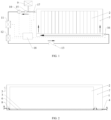
FIG. 1 is a schematic diagram of an immersion-type thermal management system for power batteries according to the invention (wherein, the arrows indicate the flow direction of liquid, and the dotted lines indicate signal connection); -
FIG. 2 is a schematic diagram of a power battery unit of the immersion-type thermal management system for power batteries according to the invention; -
FIG. 3 is a sectional view along A-A inFIG. 2 . - In the
FIGS.: 1 , box; 2, battery module; 3, liquid cooling plate; 4, external liquid inlet; 5, external liquid outlet; 6, liquid passage; 7, immersion space; 8, internal liquid outlet; 9, expansion box; 10, circulating pump; 11, water cooling unit; 12, heater; 13, check valve; 14, flow divider partition; 15, filter; 16, first temperature sensor; 17, second temperature sensor; 18, controller. - Illustrative embodiments of the invention will be described below in conjunction with accompanying drawings together with some details of the embodiments of the invention to facilitate understanding, and all these embodiments and details should be construed as illustrative merely. Therefore, those ordinarily skilled in the art should appreciate that various transformations and amendments can be made to the embodiments described here without departing from the scope and spirit of the invention. Similarly, for the sake of clarity and briefness, the description of commonly known functions and structures is omitted below.
- As shown in
FIG. 1-FIG. 3 , an embodiment of the invention provides an immersion-type thermal management system for power batteries, comprising a power battery unit and a thermal management unit; wherein, the power battery unit comprises a box 1, abattery module 2 and a liquid cooling plate 3, the box 1 is provided with an externalliquid inlet 4 and an externalliquid outlet 5, the liquid cooling plate 3 is provided with internalliquid outlets 8 and located below thebattery module 2, aliquid passage 6 is arranged in the liquid cooling plate 3, animmersion space 7 is formed in the box 1, the internalliquid outlets 8 are located between and connected to theliquid passage 6 and theimmersion space 7, the externalliquid inlet 4 is connected to theliquid passage 6, and the externalliquid outlet 5 is connected to theimmersion space 7; the thermal management unit comprises acontroller 18 and an external circulation path formed outside the box 1, the external circulation path is connected to the externalliquid inlet 4 from the externalliquid outlet 5 and comprises anexpansion box 9, a circulatingpump 10, awater cooling unit 11, aheater 12 and acheck valve 13 which are sequentially connected from the externalliquid outlet 5, and theexpansion box 9, the circulatingpump 10, thewater cooling unit 11 and theheater 12 are all connected to thecontroller 18; theexpansion box 9 is used for filtering out gas generated in the operating process of the thermal management system, the circulatingpump 10 is used for providing operating power for the whole thermal management system, thewater cooling unit 11 is used for providing a cold source required by the thermal management system, theheater 12 is used for providing a heat source required by the thermal management system, and thecheck valve 13 is used for preventing liquid in a pipeline from flowing back; liquid enters theliquid passage 6 from the external circulation path via the externalliquid inlet 4, then enters theimmersion space 7 via the internalliquid outlets 8, and when the liquid level in theimmersion space 7 reaches the position where theexternal liquid outlet 5 is located, is discharged via the externalliquid outlet 5 and enters the external circulation path; and thecontroller 18 is used for controlling the system to switch between different modes. - Wherein, more specifically, the
liquid passage 6 comprises a plurality of S-shaped passages which are arranged in parallel, a plurality offlow divider partitions 14 are arranged at the externalliquid outlet 4 to allow liquid flowing in via the externalliquid outlet 4 to uniformly enter the S-shaped passages, the externalliquid outlet 5 is formed in an upper portion of the box 1 and located above thebattery module 2, and afilter 15 is arranged between theexpansion box 9 and the circulatingpump 10 and is used for filtering out impurities in the liquid; and afirst temperature sensor 16 is arranged at the externalliquid inlet 4, connected to thecontroller 18 and used for monitoring the temperature of the liquid flowing in via the externalliquid inlet 4, and asecond temperature sensor 17 is arranged at the externalliquid outlet 5, connected to thecontroller 18 and used for monitoring the temperature of the liquid flowing out via the externalliquid outlet 5. - In this embodiment, four S-shaped passages are connected in parallel, and liquid flowing in via the external
liquid inlet 4 synchronously enters the liquid cooling plate 3 from the four of the liquid flowing in via the external liquid outlet passages, and after the liquid cooling plate 3 is full of liquid, the liquid overflows into theimmersion space 7 via the internalliquid outlets 8. - Thermally conductive silicone is arranged between the
battery module 2 and the liquid cooling plate 3 to enhance heat transfer between thebattery module 2 and the liquid cooling plate 3, the internalliquid outlets 8 are formed in two ends of the liquid cooling plate 3 and are not blocked by the thermally conductive silicone. - The thermal management system has a self-circulation mode and a static mode, and the
controller 18 controls the thermal management system to switch between a cooling mode, a heating mode, the self-circulation mode and the static mode specifically as follows: - Before running of the whole thermal management system, the circulation circuit including the box 1 of the power battery unit is filled with heat-transfer liquid.
- When the immersion-type thermal management system runs in the cooling mode, the
controller 18 sends a running instruction to the circulatingpump 10 and thewater cooling unit 11 to enable the circulatingpump 10 and thewater cooling unit 11 to work. At this moment, heat generated by thebattery module 2 will be gradually transferred to the liquid in the power battery unit, and the liquid is driven by the circulatingpump 10 to enter the external circulation path via theexternal liquid outlet 5; because gas will be generated in use of thebattery module 2 and will overflow into a cavity in the power battery unit, the heat transfer efficiency of the system and the safety of a power battery in use will be severely affected if the gas cannot be discharged in time; in view of this, the liquid entering the external circulation path first passes through theexpansion box 9 to discharge the gas generated, then flows through thefilter 15 to filter out impurities in the power battery unit, then flows into the circulatingpump 10 to improve the driving force, and then enters thewater cooling unit 11 to transfer heat absorbed from thebattery module 2 to thewater cooling unit 11 to reduce the temperature of the liquid; in this mode, theheater 12 does not work, so the liquid remains unchanged after flowing through theheater 12, and directly flows into thecheck valve 13 which is used for preventing the liquid from flowing back; finally, the liquid flows into theliquid passage 6 of the liquid cooling plate 3 via the externalliquid inlet 4 and overflows via the internalliquid outlets 8. In this way, original liquid in the power battery unit is gradually replaced, and heat, gas and impurities generated in use of thebattery module 2 are taken away, thus forming a complete power battery cooling circuit. Thecontroller 18 monitors the temperature of the liquid flowing into the power battery unit and the liquid flowing out of the power battery unit through thefirst temperature sensor 16 and thesecond temperature sensor 17 respectively to regulate the operating power of the circulatingpump 10 and thewater cooling unit 11. - Compared with the cooling mode, when the immersion-type thermal management system runs in the heating mode, the
controller 18 sends a running instruction to the circulatingpump 10 and theheater 12 to enable the circulatingpump 10 and theheater 12 to work. The immersion-type thermal management system runs in the same way as in the cooling mode in other aspects. - Compared with the cooling mode, when the immersion-type thermal management system runs in the self-circulation mode, the
controller 18 sends a running instruction to the circulatingpump 10 to enable the circulating pump to work, and the internal temperature of the power battery unit is uniformized by flowing of liquid. In this mode, neither the water cooling unit nor the heater works. - In the static mode, the thermal management system is in a static state and does not work.
- In the design of this embodiment, liquid overflows from the tops of the S-shaped passages of the liquid cooling plate 3, the
battery module 2 is directly immersed in the overflowing liquid, and the liquid in the S-shaped passages of the liquid cooling plate 3 can indirectly exchange heat with the bottom of thebattery module 2, thus solving the problem that the heat-exchange uniformity is poor because the bottom of thebattery module 2 cannot be immersed and guaranteeing good heat-exchange uniformity of thebattery module 2. - In this design, the liquid outlet of the power battery unit is formed in the upper portion of the box 1. Considering that flammable and combustible gas that needs to be discharged in time will be generated in use of the power battery and the generated gas will be undoubtedly accumulated in the upper portion of the box 1 when the cavity of the power battery unit is full of liquid, the liquid outlet is formed in the upper portion of the box 1 to easily discharge the generated gas along with the liquid in the box, thus greatly reducing the risk of thermal safety accidents of the power battery unit.
- In the invention, the
expansion box 9 is arranged in the system circuit and is connected to a position close to the externalliquid outlet 5 of the power battery unit, such that gas taken out of the power battery unit by liquid can be quickly and effectively absorbed into theexpansion box 9 to be discharged into the atmosphere, thus reducing harm of the gas to the system. - In this design, four S-shaped passages connected in parallel are adopted, and liquid flows in from two ends of the S-shaped passages, thus guaranteeing the temperature uniformity of liquid in the liquid cooling plate 3; and the internal
liquid outlets 8 are arranged above the S-shaped passages at the two ends of the liquid cooling plate 3, thus guaranteeing the temperature uniformity of liquid entering the cavity of the power battery unit. - In the invention, the water-
cooling unit 11 and theheater 12 are arranged in the system circuit, such that the system can both cool and heat a power battery, thus improving the working adaptivity of the power battery in high-temperature and low-temperature harsh conditions. - In addition, a liquid level sensor is arranged in the
expansion box 9 and connected to thecontroller 18 through a signal acquisition line. The flow rate of liquid in the system can be properly controlled by changing the liquid level, and a liquid supply signal can be provided, thus facilitating efficient and safe use of the thermal management system. - In this embodiment, the number of the external
liquid outlets 4 is two, the interior of the liquid cooling plate 3 is divided into two liquid inlet spaces, and theexternal liquid outlets 4 are connected to theliquid passages 6 in the liquid inlet spaces in one-to-one correspondence to allow liquid to enter the liquid cooling plate 3 from the external circulation path. - In some other embodiments, the number of the external
liquid outlets 4 can be designed according to the size of the liquid cooling plate 3, the amount of liquid entering the liquid cooling plate 3, a desired heating/cooling effect and other factors, for example, the number of the externalliquid outlets 4 may be 1, 3, 4 or 5. Correspondingly, the interior of the liquid cooling plate 3 is divided into the same number of liquid inlet spaces, the externalliquid outlets 4 are connected to the liquid inlet spaces in one-to-one correspondence, and aliquid passage 6 is arranged in each liquid inlet space. - Compared with the prior art, the immersion-type thermal management system for power batteries provided by the invention has a heating mode and a cooling mode and can be easily controlled as required, and liquid can sufficiently exchange heat with the battery module, so the efficiency is high, the effect is good, the problem of poor thermal uniformity and safety in use of power batteries is effectively solved, efficient and convenient thermal management of the power batteries is facilitated, and thermal runaway accidents of the power batteries are prevented.
- The above specific embodiments are not intended to limit the protection scope of the invention. Those skilled in the art should understand that various amendments, combinations, subcombinations and substitutions can be made depending on design requirements and other factors. Any amendments, equivalent substitutions and improvements made based on the spirit and principle of the invention should also fall within the protection scope of the invention.
Claims (10)
- An immersion-type thermal management system for power batteries, comprising a power battery unit and a thermal management unit, wherein:the power battery unit comprises a box, a battery module and a liquid cooling plate, the box is provided with an external liquid inlet and an external liquid outlet, the liquid cooling plate is provided with internal liquid outlets and located below the battery module, a liquid passage is arranged in the liquid cooling plate, an immersion space is formed in the box, the internal liquid outlets are located between and connected to the liquid passage and the immersion space, the external liquid inlet is connected to the liquid passage, and the external liquid outlet is connected to the immersion space;the thermal management unit comprises a controller and an external circulation path formed outside the box, the external circulation path is connected to the external liquid inlet from the external liquid outlet and comprises an expansion box, a circulating pump, a water cooling unit, a heater and a check valve which are sequentially connected from the external liquid outlet, and the expansion box, the circulating pump, the water cooling unit and the heater are all connected to the controller;liquid enters the liquid passage from the external circulation path via the external liquid inlet, then enters the immersion space via the internal liquid outlets, and then enters the external circulation path via the external liquid outlet;the system at least has a cooling mode and a heating mode, and the controller controls the system to switch between the cooling mode and the heating mode.
- The immersion-type thermal management system for power batteries according to Claim 1, wherein the liquid passage comprises a plurality of S-shaped passages which are arranged in parallel, and a plurality of liquid diverter partitions are arranged at the external liquid inlet to allow liquid flowing in via the external liquid inlet to enter the S-shaped passages uniformly.
- The immersion-type thermal management system for power batteries according to Claim 1, wherein the external liquid outlet is formed in an upper portion of the box and located above the battery module.
- The immersion-type thermal management system for power batteries according to Claim 1, wherein a filter is arranged between the expansion box and the circulating pump.
- The immersion-type thermal management system for power batteries according to Claim 1, wherein a first temperature sensor is arranged at the external liquid inlet, connected to the controller and used for monitoring a temperature of the liquid flowing in via the external liquid inlet.
- The immersion-type thermal management system for power batteries according to Claim 1, wherein a second temperature sensor is arranged at the external liquid outlet, connected to the controller and used for monitoring a temperature of the liquid flowing out via the external liquid outlet.
- The immersion-type thermal management system for power batteries according to Claim 1, wherein the system further has a self-circulation mode and a static mode, and the controller controls the system to switch between the cooling mode, the heating mode, the self-circulation mode and the static mode.
- The immersion-type thermal management system for power batteries according to Claim 1, wherein thermally conductive silicone is arranged between the battery module and the liquid cooling plate.
- The immersion-type thermal management system for power batteries according to Claim 1, wherein the box is provided with N said external liquid inlets, N is a positive integer, an interior of the liquid cooling plate is divided into N liquid inlet spaces, the external liquid inlets are connected to the liquid inlet spaces in one-to-one correspondence, and the liquid passage is arranged in each said liquid inlet space.
- The immersion-type thermal management system for power batteries according to Claim 1, wherein the internal liquid outlets are formed in two ends of the liquid cooling plate.
Applications Claiming Priority (2)
| Application Number | Priority Date | Filing Date | Title |
|---|---|---|---|
| CN202211575986.6A CN115863844A (en) | 2022-12-09 | 2022-12-09 | Immersed power battery thermal management system |
| PCT/CN2023/106476 WO2024119822A1 (en) | 2022-12-09 | 2023-07-10 | Immersion-type power battery thermal management system |
Publications (3)
| Publication Number | Publication Date |
|---|---|
| EP4404336A1 true EP4404336A1 (en) | 2024-07-24 |
| EP4404336A4 EP4404336A4 (en) | 2025-06-25 |
| EP4404336B1 EP4404336B1 (en) | 2026-03-04 |
Family
ID=85671350
Family Applications (1)
| Application Number | Title | Priority Date | Filing Date |
|---|---|---|---|
| EP23848459.6A Active EP4404336B1 (en) | 2022-12-09 | 2023-07-10 | Immersion-type power battery thermal management system |
Country Status (4)
| Country | Link |
|---|---|
| EP (1) | EP4404336B1 (en) |
| CN (1) | CN115863844A (en) |
| AU (1) | AU2023316922B2 (en) |
| WO (1) | WO2024119822A1 (en) |
Families Citing this family (9)
| Publication number | Priority date | Publication date | Assignee | Title |
|---|---|---|---|---|
| CN113809432B (en) * | 2021-09-10 | 2025-05-30 | 哲弗智能系统(上海)有限公司 | Battery Thermal Management System |
| CN115863844A (en) * | 2022-12-09 | 2023-03-28 | 江苏汇智高端工程机械创新中心有限公司 | Immersed power battery thermal management system |
| CN116345017A (en) * | 2023-04-14 | 2023-06-27 | 天津市捷威动力工业有限公司 | Power battery system and new energy vehicles |
| CN116864855A (en) * | 2023-07-18 | 2023-10-10 | 中国电建集团江西省电力建设有限公司 | Liquid cooling device and cooling control method thereof |
| CN117154288A (en) * | 2023-09-19 | 2023-12-01 | 浙江冠宇电源有限公司 | A battery pack and thermal management system |
| WO2026000962A1 (en) * | 2024-06-28 | 2026-01-02 | 国联汽车动力电池研究院有限责任公司 | Battery performance testing device and battery performance testing method |
| CN119764647A (en) * | 2024-06-30 | 2025-04-04 | 比亚迪股份有限公司 | Liquid circulation device, energy storage device and energy storage system |
| CN223427552U (en) * | 2024-09-24 | 2025-10-10 | 惠州亿纬锂能股份有限公司 | Battery module and battery pack |
| CN119447571B (en) * | 2024-10-31 | 2026-04-03 | 清安储能技术(重庆)有限公司 | A top-immersion battery pack |
Family Cites Families (8)
| Publication number | Priority date | Publication date | Assignee | Title |
|---|---|---|---|---|
| JP3130238B2 (en) * | 1995-12-18 | 2001-01-31 | 日本碍子株式会社 | Sodium-sulfur battery |
| US20100104927A1 (en) * | 2008-10-29 | 2010-04-29 | Scott Albright | Temperature-controlled battery configuration |
| CN214043778U (en) * | 2020-12-22 | 2021-08-24 | 河南电池研究院有限公司 | Immersion type liquid cooling battery module with integrated liquid cooling board |
| FR3125635B1 (en) * | 2021-07-20 | 2024-02-09 | Psa Automobiles Sa | ELECTRIC STORAGE DEVICE WITH PARTIALLY IMMERSED CELLS |
| CN217214871U (en) * | 2021-10-29 | 2022-08-16 | 广东合一新材料研究院有限公司 | Stable and reliable energy storage battery pack heat exchange system |
| CN216054908U (en) * | 2021-10-29 | 2022-03-15 | 广东合一新材料研究院有限公司 | Immersed heat exchange system of battery energy storage system |
| CN217426881U (en) * | 2022-04-06 | 2022-09-13 | 周锡卫 | Contact liquid cooling plate and immersion liquid cooling battery module |
| CN115863844A (en) * | 2022-12-09 | 2023-03-28 | 江苏汇智高端工程机械创新中心有限公司 | Immersed power battery thermal management system |
-
2022
- 2022-12-09 CN CN202211575986.6A patent/CN115863844A/en active Pending
-
2023
- 2023-07-10 AU AU2023316922A patent/AU2023316922B2/en active Active
- 2023-07-10 WO PCT/CN2023/106476 patent/WO2024119822A1/en not_active Ceased
- 2023-07-10 EP EP23848459.6A patent/EP4404336B1/en active Active
Also Published As
| Publication number | Publication date |
|---|---|
| AU2023316922A1 (en) | 2024-06-27 |
| EP4404336B1 (en) | 2026-03-04 |
| WO2024119822A1 (en) | 2024-06-13 |
| CN115863844A (en) | 2023-03-28 |
| EP4404336A4 (en) | 2025-06-25 |
| AU2023316922B2 (en) | 2025-10-23 |
Similar Documents
| Publication | Publication Date | Title |
|---|---|---|
| EP4404336A1 (en) | Immersion-type power battery thermal management system | |
| CN209691817U (en) | A kind of cooling power battery assembly structure of immersion type for electric vehicle | |
| JP2017157541A (en) | Battery pack thermal management system | |
| CN211376819U (en) | Fuel cell thermal management system | |
| KR102217341B1 (en) | Battery system including water cooling type cooling apparatus and flow control device assembly for the same | |
| WO2019037309A1 (en) | Cooling device and liquid-cooled heat dissipation system | |
| CN220732162U (en) | Electrical equipment and energy storage system | |
| CN114220989A (en) | Heat radiation system of fuel cell stack | |
| CN116365103A (en) | A submerged liquid-cooled energy storage battery pack heat exchange device | |
| CN116424125A (en) | Charging and swapping station thermal management system and charging and swapping station | |
| CN119419410A (en) | Thermal management devices and energy storage cabinets | |
| CN111509333A (en) | Partitioned thermal management control method for battery pack | |
| WO2024159800A1 (en) | Cooling system of vehicle, and vehicle | |
| CN222562776U (en) | Immersion liquid cooling device and energy storage system | |
| CN222572035U (en) | A thermal management integrated device | |
| CN214647452U (en) | Electronic bull-dozer thermal management system and electronic bull-dozer | |
| CN119009251A (en) | Liquid cooling unit for energy storage system and operation method thereof | |
| CN116437626A (en) | A security protection device for 5G distribution network communication | |
| CN110544807A (en) | Liquid cooling system of power battery and control method thereof | |
| CN117317467A (en) | Energy storage battery module combined heat dissipation device and control method thereof | |
| CN116845432A (en) | Battery thermal management unit integrating heat pump system and electric heat dissipation system | |
| CN222507771U (en) | Thermal management system and energy storage system | |
| LU500023B1 (en) | Liquid-cooled double-cycle heat management box for power lithium battery pack | |
| CN117386483B (en) | An oil cooler assembly | |
| CN213417532U (en) | Cooling system of road microwave maintenance vehicle |
Legal Events
| Date | Code | Title | Description |
|---|---|---|---|
| STAA | Information on the status of an ep patent application or granted ep patent |
Free format text: STATUS: UNKNOWN |
|
| STAA | Information on the status of an ep patent application or granted ep patent |
Free format text: STATUS: THE INTERNATIONAL PUBLICATION HAS BEEN MADE |
|
| PUAI | Public reference made under article 153(3) epc to a published international application that has entered the european phase |
Free format text: ORIGINAL CODE: 0009012 |
|
| STAA | Information on the status of an ep patent application or granted ep patent |
Free format text: STATUS: REQUEST FOR EXAMINATION WAS MADE |
|
| 17P | Request for examination filed |
Effective date: 20240214 |
|
| AK | Designated contracting states |
Kind code of ref document: A1 Designated state(s): AL AT BE BG CH CY CZ DE DK EE ES FI FR GB GR HR HU IE IS IT LI LT LU LV MC ME MK MT NL NO PL PT RO RS SE SI SK SM TR |
|
| A4 | Supplementary search report drawn up and despatched |
Effective date: 20250527 |
|
| RIC1 | Information provided on ipc code assigned before grant |
Ipc: H01M 10/615 20140101ALI20250521BHEP Ipc: H01M 10/613 20140101ALI20250521BHEP Ipc: H01M 10/617 20140101AFI20250521BHEP |
|
| GRAP | Despatch of communication of intention to grant a patent |
Free format text: ORIGINAL CODE: EPIDOSNIGR1 |
|
| STAA | Information on the status of an ep patent application or granted ep patent |
Free format text: STATUS: GRANT OF PATENT IS INTENDED |
|
| INTG | Intention to grant announced |
Effective date: 20251120 |
|
| GRAS | Grant fee paid |
Free format text: ORIGINAL CODE: EPIDOSNIGR3 |
|
| GRAA | (expected) grant |
Free format text: ORIGINAL CODE: 0009210 |
|
| STAA | Information on the status of an ep patent application or granted ep patent |
Free format text: STATUS: THE PATENT HAS BEEN GRANTED |
|
| AK | Designated contracting states |
Kind code of ref document: B1 Designated state(s): AL AT BE BG CH CY CZ DE DK EE ES FI FR GB GR HR HU IE IS IT LI LT LU LV MC ME MK MT NL NO PL PT RO RS SE SI SK SM TR |
|
| DAV | Request for validation of the european patent (deleted) | ||
| DAX | Request for extension of the european patent (deleted) | ||
| REG | Reference to a national code |
Ref country code: CH Ref legal event code: F10 Free format text: ST27 STATUS EVENT CODE: U-0-0-F10-F00 (AS PROVIDED BY THE NATIONAL OFFICE) Effective date: 20260304 Ref country code: GB Ref legal event code: FG4D |
|
| REG | Reference to a national code |
Ref country code: IE Ref legal event code: FG4D |
|
| REG | Reference to a national code |
Ref country code: DE Ref legal event code: R096 Ref document number: 602023013154 Country of ref document: DE |
|
| P01 | Opt-out of the competence of the unified patent court (upc) registered |
Free format text: CASE NUMBER: UPC_APP_0008256_4404336/2026 Effective date: 20260227 |