EP4404318A1 - Battery - Google Patents
Battery Download PDFInfo
- Publication number
- EP4404318A1 EP4404318A1 EP24151620.2A EP24151620A EP4404318A1 EP 4404318 A1 EP4404318 A1 EP 4404318A1 EP 24151620 A EP24151620 A EP 24151620A EP 4404318 A1 EP4404318 A1 EP 4404318A1
- Authority
- EP
- European Patent Office
- Prior art keywords
- exterior body
- metal exterior
- bottom plate
- positive electrode
- negative electrode
- Prior art date
- Legal status (The legal status is an assumption and is not a legal conclusion. Google has not performed a legal analysis and makes no representation as to the accuracy of the status listed.)
- Pending
Links
Images




Classifications
-
- H—ELECTRICITY
- H01—ELECTRIC ELEMENTS
- H01M—PROCESSES OR MEANS, e.g. BATTERIES, FOR THE DIRECT CONVERSION OF CHEMICAL ENERGY INTO ELECTRICAL ENERGY
- H01M50/00—Constructional details or processes of manufacture of the non-active parts of electrochemical cells other than fuel cells, e.g. hybrid cells
- H01M50/50—Current conducting connections for cells or batteries
- H01M50/543—Terminals
- H01M50/545—Terminals formed by the casing of the cells
-
- H—ELECTRICITY
- H01—ELECTRIC ELEMENTS
- H01M—PROCESSES OR MEANS, e.g. BATTERIES, FOR THE DIRECT CONVERSION OF CHEMICAL ENERGY INTO ELECTRICAL ENERGY
- H01M10/00—Secondary cells; Manufacture thereof
- H01M10/05—Accumulators with non-aqueous electrolyte
- H01M10/058—Construction or manufacture
-
- H—ELECTRICITY
- H01—ELECTRIC ELEMENTS
- H01M—PROCESSES OR MEANS, e.g. BATTERIES, FOR THE DIRECT CONVERSION OF CHEMICAL ENERGY INTO ELECTRICAL ENERGY
- H01M50/00—Constructional details or processes of manufacture of the non-active parts of electrochemical cells other than fuel cells, e.g. hybrid cells
- H01M50/10—Primary casings; Jackets or wrappings
- H01M50/102—Primary casings; Jackets or wrappings characterised by their shape or physical structure
-
- E—FIXED CONSTRUCTIONS
- E01—CONSTRUCTION OF ROADS, RAILWAYS, OR BRIDGES
- E01H—STREET CLEANING; CLEANING OF PERMANENT WAYS; CLEANING BEACHES; DISPERSING OR PREVENTING FOG IN GENERAL CLEANING STREET OR RAILWAY FURNITURE OR TUNNEL WALLS
- E01H5/00—Removing snow or ice from roads or like surfaces; Grading or roughening snow or ice
- E01H5/10—Removing snow or ice from roads or like surfaces; Grading or roughening snow or ice by application of heat for melting snow or ice, whether cleared or not, combined or not with clearing or removing mud or water, e.g. burners for melting in situ, heated clearing instruments ; Cleaning snow by blowing or suction only
- E01H5/106—Clearing snow or ice exclusively by means of rays or streams of gas or steam or by suction with or without melting
-
- E—FIXED CONSTRUCTIONS
- E01—CONSTRUCTION OF ROADS, RAILWAYS, OR BRIDGES
- E01C—CONSTRUCTION OF, OR SURFACES FOR, ROADS, SPORTS GROUNDS, OR THE LIKE; MACHINES OR AUXILIARY TOOLS FOR CONSTRUCTION OR REPAIR
- E01C11/00—Details of pavings
- E01C11/24—Methods or arrangements for preventing slipperiness or protecting against influences of the weather
- E01C11/26—Permanently installed heating or blowing devices ; Mounting thereof
-
- H—ELECTRICITY
- H01—ELECTRIC ELEMENTS
- H01M—PROCESSES OR MEANS, e.g. BATTERIES, FOR THE DIRECT CONVERSION OF CHEMICAL ENERGY INTO ELECTRICAL ENERGY
- H01M10/00—Secondary cells; Manufacture thereof
- H01M10/04—Construction or manufacture in general
- H01M10/0413—Large-sized flat cells or batteries for motive or stationary systems with plate-like electrodes
- H01M10/0418—Large-sized flat cells or batteries for motive or stationary systems with plate-like electrodes with bipolar electrodes
-
- H—ELECTRICITY
- H01—ELECTRIC ELEMENTS
- H01M—PROCESSES OR MEANS, e.g. BATTERIES, FOR THE DIRECT CONVERSION OF CHEMICAL ENERGY INTO ELECTRICAL ENERGY
- H01M10/00—Secondary cells; Manufacture thereof
- H01M10/05—Accumulators with non-aqueous electrolyte
- H01M10/052—Li-accumulators
-
- H—ELECTRICITY
- H01—ELECTRIC ELEMENTS
- H01M—PROCESSES OR MEANS, e.g. BATTERIES, FOR THE DIRECT CONVERSION OF CHEMICAL ENERGY INTO ELECTRICAL ENERGY
- H01M10/00—Secondary cells; Manufacture thereof
- H01M10/05—Accumulators with non-aqueous electrolyte
- H01M10/052—Li-accumulators
- H01M10/0525—Rocking-chair batteries, i.e. batteries with lithium insertion or intercalation in both electrodes; Lithium-ion batteries
-
- H—ELECTRICITY
- H01—ELECTRIC ELEMENTS
- H01M—PROCESSES OR MEANS, e.g. BATTERIES, FOR THE DIRECT CONVERSION OF CHEMICAL ENERGY INTO ELECTRICAL ENERGY
- H01M10/00—Secondary cells; Manufacture thereof
- H01M10/05—Accumulators with non-aqueous electrolyte
- H01M10/056—Accumulators with non-aqueous electrolyte characterised by the materials used as electrolytes, e.g. mixed inorganic/organic electrolytes
-
- H—ELECTRICITY
- H01—ELECTRIC ELEMENTS
- H01M—PROCESSES OR MEANS, e.g. BATTERIES, FOR THE DIRECT CONVERSION OF CHEMICAL ENERGY INTO ELECTRICAL ENERGY
- H01M10/00—Secondary cells; Manufacture thereof
- H01M10/05—Accumulators with non-aqueous electrolyte
- H01M10/058—Construction or manufacture
- H01M10/0585—Construction or manufacture of accumulators having only flat construction elements, i.e. flat positive electrodes, flat negative electrodes and flat separators
-
- H—ELECTRICITY
- H01—ELECTRIC ELEMENTS
- H01M—PROCESSES OR MEANS, e.g. BATTERIES, FOR THE DIRECT CONVERSION OF CHEMICAL ENERGY INTO ELECTRICAL ENERGY
- H01M50/00—Constructional details or processes of manufacture of the non-active parts of electrochemical cells other than fuel cells, e.g. hybrid cells
- H01M50/10—Primary casings; Jackets or wrappings
- H01M50/102—Primary casings; Jackets or wrappings characterised by their shape or physical structure
- H01M50/103—Primary casings; Jackets or wrappings characterised by their shape or physical structure prismatic or rectangular
-
- H—ELECTRICITY
- H01—ELECTRIC ELEMENTS
- H01M—PROCESSES OR MEANS, e.g. BATTERIES, FOR THE DIRECT CONVERSION OF CHEMICAL ENERGY INTO ELECTRICAL ENERGY
- H01M50/00—Constructional details or processes of manufacture of the non-active parts of electrochemical cells other than fuel cells, e.g. hybrid cells
- H01M50/10—Primary casings; Jackets or wrappings
- H01M50/102—Primary casings; Jackets or wrappings characterised by their shape or physical structure
- H01M50/109—Primary casings; Jackets or wrappings characterised by their shape or physical structure of button or coin shape
-
- H—ELECTRICITY
- H01—ELECTRIC ELEMENTS
- H01M—PROCESSES OR MEANS, e.g. BATTERIES, FOR THE DIRECT CONVERSION OF CHEMICAL ENERGY INTO ELECTRICAL ENERGY
- H01M50/00—Constructional details or processes of manufacture of the non-active parts of electrochemical cells other than fuel cells, e.g. hybrid cells
- H01M50/10—Primary casings; Jackets or wrappings
- H01M50/116—Primary casings; Jackets or wrappings characterised by the material
- H01M50/117—Inorganic material
- H01M50/119—Metals
-
- H—ELECTRICITY
- H01—ELECTRIC ELEMENTS
- H01M—PROCESSES OR MEANS, e.g. BATTERIES, FOR THE DIRECT CONVERSION OF CHEMICAL ENERGY INTO ELECTRICAL ENERGY
- H01M50/00—Constructional details or processes of manufacture of the non-active parts of electrochemical cells other than fuel cells, e.g. hybrid cells
- H01M50/10—Primary casings; Jackets or wrappings
- H01M50/14—Primary casings; Jackets or wrappings for protecting against damage caused by external factors
-
- H—ELECTRICITY
- H01—ELECTRIC ELEMENTS
- H01M—PROCESSES OR MEANS, e.g. BATTERIES, FOR THE DIRECT CONVERSION OF CHEMICAL ENERGY INTO ELECTRICAL ENERGY
- H01M50/00—Constructional details or processes of manufacture of the non-active parts of electrochemical cells other than fuel cells, e.g. hybrid cells
- H01M50/10—Primary casings; Jackets or wrappings
- H01M50/14—Primary casings; Jackets or wrappings for protecting against damage caused by external factors
- H01M50/141—Primary casings; Jackets or wrappings for protecting against damage caused by external factors for protecting against humidity
-
- H—ELECTRICITY
- H01—ELECTRIC ELEMENTS
- H01M—PROCESSES OR MEANS, e.g. BATTERIES, FOR THE DIRECT CONVERSION OF CHEMICAL ENERGY INTO ELECTRICAL ENERGY
- H01M50/00—Constructional details or processes of manufacture of the non-active parts of electrochemical cells other than fuel cells, e.g. hybrid cells
- H01M50/50—Current conducting connections for cells or batteries
- H01M50/543—Terminals
- H01M50/547—Terminals characterised by the disposition of the terminals on the cells
- H01M50/548—Terminals characterised by the disposition of the terminals on the cells on opposite sides of the cell
-
- H—ELECTRICITY
- H01—ELECTRIC ELEMENTS
- H01M—PROCESSES OR MEANS, e.g. BATTERIES, FOR THE DIRECT CONVERSION OF CHEMICAL ENERGY INTO ELECTRICAL ENERGY
- H01M50/00—Constructional details or processes of manufacture of the non-active parts of electrochemical cells other than fuel cells, e.g. hybrid cells
- H01M50/50—Current conducting connections for cells or batteries
- H01M50/543—Terminals
- H01M50/552—Terminals characterised by their shape
-
- H—ELECTRICITY
- H01—ELECTRIC ELEMENTS
- H01M—PROCESSES OR MEANS, e.g. BATTERIES, FOR THE DIRECT CONVERSION OF CHEMICAL ENERGY INTO ELECTRICAL ENERGY
- H01M50/00—Constructional details or processes of manufacture of the non-active parts of electrochemical cells other than fuel cells, e.g. hybrid cells
- H01M50/50—Current conducting connections for cells or batteries
- H01M50/543—Terminals
- H01M50/552—Terminals characterised by their shape
- H01M50/553—Terminals adapted for prismatic, pouch or rectangular cells
-
- H—ELECTRICITY
- H01—ELECTRIC ELEMENTS
- H01M—PROCESSES OR MEANS, e.g. BATTERIES, FOR THE DIRECT CONVERSION OF CHEMICAL ENERGY INTO ELECTRICAL ENERGY
- H01M50/00—Constructional details or processes of manufacture of the non-active parts of electrochemical cells other than fuel cells, e.g. hybrid cells
- H01M50/50—Current conducting connections for cells or batteries
- H01M50/543—Terminals
- H01M50/562—Terminals characterised by the material
-
- H—ELECTRICITY
- H01—ELECTRIC ELEMENTS
- H01M—PROCESSES OR MEANS, e.g. BATTERIES, FOR THE DIRECT CONVERSION OF CHEMICAL ENERGY INTO ELECTRICAL ENERGY
- H01M50/00—Constructional details or processes of manufacture of the non-active parts of electrochemical cells other than fuel cells, e.g. hybrid cells
- H01M50/50—Current conducting connections for cells or batteries
- H01M50/572—Means for preventing undesired use or discharge
- H01M50/584—Means for preventing undesired use or discharge for preventing incorrect connections inside or outside the batteries
-
- H—ELECTRICITY
- H01—ELECTRIC ELEMENTS
- H01M—PROCESSES OR MEANS, e.g. BATTERIES, FOR THE DIRECT CONVERSION OF CHEMICAL ENERGY INTO ELECTRICAL ENERGY
- H01M50/00—Constructional details or processes of manufacture of the non-active parts of electrochemical cells other than fuel cells, e.g. hybrid cells
- H01M50/50—Current conducting connections for cells or batteries
- H01M50/572—Means for preventing undesired use or discharge
- H01M50/584—Means for preventing undesired use or discharge for preventing incorrect connections inside or outside the batteries
- H01M50/586—Means for preventing undesired use or discharge for preventing incorrect connections inside or outside the batteries inside the batteries, e.g. incorrect connections of electrodes
-
- H—ELECTRICITY
- H01—ELECTRIC ELEMENTS
- H01M—PROCESSES OR MEANS, e.g. BATTERIES, FOR THE DIRECT CONVERSION OF CHEMICAL ENERGY INTO ELECTRICAL ENERGY
- H01M50/00—Constructional details or processes of manufacture of the non-active parts of electrochemical cells other than fuel cells, e.g. hybrid cells
- H01M50/50—Current conducting connections for cells or batteries
- H01M50/572—Means for preventing undesired use or discharge
- H01M50/584—Means for preventing undesired use or discharge for preventing incorrect connections inside or outside the batteries
- H01M50/59—Means for preventing undesired use or discharge for preventing incorrect connections inside or outside the batteries characterised by the protection means
-
- H—ELECTRICITY
- H01—ELECTRIC ELEMENTS
- H01M—PROCESSES OR MEANS, e.g. BATTERIES, FOR THE DIRECT CONVERSION OF CHEMICAL ENERGY INTO ELECTRICAL ENERGY
- H01M2300/00—Electrolytes
- H01M2300/0085—Immobilising or gelification of electrolyte
-
- Y—GENERAL TAGGING OF NEW TECHNOLOGICAL DEVELOPMENTS; GENERAL TAGGING OF CROSS-SECTIONAL TECHNOLOGIES SPANNING OVER SEVERAL SECTIONS OF THE IPC; TECHNICAL SUBJECTS COVERED BY FORMER USPC CROSS-REFERENCE ART COLLECTIONS [XRACs] AND DIGESTS
- Y02—TECHNOLOGIES OR APPLICATIONS FOR MITIGATION OR ADAPTATION AGAINST CLIMATE CHANGE
- Y02E—REDUCTION OF GREENHOUSE GAS [GHG] EMISSIONS, RELATED TO ENERGY GENERATION, TRANSMISSION OR DISTRIBUTION
- Y02E60/00—Enabling technologies; Technologies with a potential or indirect contribution to GHG emissions mitigation
- Y02E60/10—Energy storage using batteries
Definitions
- the present disclosure relates to a battery.
- JP-A Japanese Patent Application Laid-Open
- JP-A No. 2021-150073 discloses a solid-state battery having: an exterior body; a sealing portion provided at the exterior body; a bipolar electrode body accommodated at the inner side of the sealing portion of the exterior body; a tab that passes-through the sealing portion from the bipolar electrode body and projects-out to the exterior of the exterior body; and a heat conducting portion provided at the interior of the exterior body.
- the heat conducting portion is insulating, and contains a resin and a heat conducting material whose heat conductivity is higher than the resin. The heat conducting portion contacts the bipolar electrode body and the tab.
- JP-A No. 2017-220447 discloses an all-solid-state battery including: a layered battery in which plural collector layers, positive electrode composite material layers, solid electrolyte layers and negative electrode composite material layers are respectively layered, and the collector layer, the positive electrode composite material layer and the negative electrode composite material layer structure a bipolar electrode layer; outermost collectors that structure the layering direction both end surfaces of the layered battery; and resins that cover only the side surfaces of the layered battery.
- At least one layer among the collector layer, the positive electrode composite material layer, the solid electrolyte layer and the negative electrode composite material layer extends-out toward the outer side further than the other layers and is an extending layer.
- a plurality of these extending layers extend-out at the side surfaces of the layered battery.
- the resins enter into the gaps between ones of the extending layers and others of the extending layers.
- a battery case for sealing the layered battery other than the outermost collectors is structured by the outermost collectors and the resins, and the outermost collectors are the battery terminals.
- International Publication No. 2021/149644 discloses a secondary battery formed to have an electrode assembly and an exterior body that houses the electrode assembly.
- the exterior body is formed to have a two-part structure of a first metal exterior body and a second metal exterior body.
- the first metal exterior body and the second metal exterior body that are metal members are assembled together without being caulked.
- a laminate film for example is used as the exterior body.
- moisture permeation resistance i.e., water vapor barrier performance
- the surface area of the region where the end portions of the laminate film are thermally welded must be made to be large.
- the structural efficiency of the battery thereby deteriorates.
- a terminal for external connection must be exposed to the exterior of the laminate film from a side surface side of the electrode body, and the structural efficiency deteriorates for this reason as well.
- the present disclosure was made in view of the above-described circumstances, and an object thereof is to provide a battery that maintains moisture permeation resistance and has good structural efficiency.
- a battery of a first aspect of the present disclosure including:
- a battery of a second aspect according to the present disclosure is the battery of the first aspect, wherein:
- a battery of a third aspect according to the present disclosure is the battery of the second aspect, wherein:
- a battery of a fourth aspect according to the present disclosure is the battery of the second aspect or the third aspect, wherein the metal exterior body at which the surface area of the bottom plate is larger is the negative electrode metal exterior body.
- a battery of a fifth aspect according to the present disclosure is the battery of any one of the second aspect to the fourth aspect, wherein:
- a battery of a sixth aspect according to the present disclosure is the battery of any one of the first aspect to the fifth aspect, wherein the battery is a solid-state battery.
- a battery of a seventh aspect according to the present disclosure is the battery of any one of the first aspect to the sixth aspect, wherein, at the electrode body, plural bipolar electrodes are layered via solid electrolyte layers.
- a battery that maintains moisture permeation resistance and has good structural efficiency.
- Fig. 1 is a schematic sectional view illustrating a battery relating to an embodiment of the present disclosure.
- Fig. 2 is a schematic perspective view illustrating an electrode body, a positive electrode foil and a negative electrode foil of the battery relating to the embodiment of the present disclosure.
- a battery 10 relating to the present disclosure has an electrode body 2, a metal exterior body pair formed from a positive electrode metal exterior body 41 and a negative electrode metal exterior body 42, and resins 6A and 6B. Further, as illustrated in Fig.
- the battery has a positive electrode foil 2A, which is provided between the electrode body 2 and the positive electrode metal exterior body 41 so as to contact the positive electrode side surface of the electrode body 2, and a negative electrode foil 2B, which is provided between the electrode body 2 and the negative electrode metal exterior body 42 so as to contact the negative electrode side surface of the electrode body 2.
- the positive electrode foil 2A and the negative electrode foil 2B are omitted in Fig. 1 .
- Fig. 3 is a schematic perspective view illustrating only the positive electrode metal exterior body 41 and the negative electrode metal exterior body 42 of the battery relating to the embodiment of the present disclosure.
- the positive electrode metal exterior body 41 at the metal exterior body pair is formed of metal, and is disposed so as to contact the positive electrode foil 2A.
- the negative electrode metal exterior body 42 is formed of metal, and is disposed so as to contact the negative electrode foil 2B. At least portions of the outer surfaces of the positive electrode metal exterior body 41 and the negative electrode metal exterior body 42 of the metal exterior body pair are exposed to as to enable electrical connection with the exterior.
- the positive electrode metal exterior body 41 is formed in the shape of a box having a bottom plate 41A that is quadrilateral and four side plates 41B that each share one side with the bottom plate 41A.
- the positive electrode metal exterior body 41 houses the electrode body 2 at the inner side of the box shape that is formed by the bottom plate 41A and the side plates 41B.
- the negative electrode metal exterior body 42 is formed in the shape of a box having a bottom plate 42A that is quadrilateral and four side plates 42B that each share one side with the bottom plate 42A.
- the negative electrode metal exterior body 42 houses the electrode body 2 at the inner side of the box shape that is formed by the bottom plate 42A and the side plates 42B.
- the positive electrode metal exterior body 41 and the negative electrode metal exterior body 42 are superposed such that the sides having the side plates 41B and the sides having the side plates 42B face one another.
- the surface area of the bottom plate 42A at the negative electrode metal exterior body 42 is larger than that of the bottom plate 41A at the positive electrode metal exterior body 41, and all of the side plates 41B of the positive electrode metal exterior body 41 are accommodated at the inner sides of all of the side plates 42B of the negative electrode metal exterior body 42.
- the resins 6A and 6B fix the electrode body 2 and the metal exterior body pair that is formed from the positive electrode metal exterior body 41 and the negative electrode metal exterior body 42.
- the resin 6A is interposed between the side surfaces of the electrode body 2 and the side plates 41B of the positive electrode metal exterior body 41, and the side surfaces of the electrode body 2 are covered by the resin 6A.
- the resin 6B is interposed between the side plates 41B of the positive electrode metal exterior body 41 and the side plates 42B of the negative electrode metal exterior body 42.
- the side surfaces of the electrode body 2 are insulated from the metal exterior body pair, which is formed from the positive electrode metal exterior body 41 and the negative electrode metal exterior body 42, by the resins 6A and 6B.
- the positive electrode metal exterior body 41 and the negative electrode metal exterior body 42 are insulated by the resins 6A and 6B.
- the positive electrode metal exterior body 41, the negative electrode metal exterior body 42 and the side surfaces of the electrode body 2 are respectively insulated by the resins 6A and 6B, and the occurrence of short circuits is thereby suppressed.
- a laminate film is used as the exterior body.
- one laminate film is folded-over and covers the electrode body, and one end side and the another end side of the laminate film are superposed together and are sealed by heat welding.
- Fig. 5 there is also the example of a battery 20 in which two laminate films 24A and 24B are superposed and cover an electrode body 22 that has terminals 28, and the battery 20 is sealed due to the end portions of the two laminate films 24A and 24B being heat welded together.
- sealing portions the surface areas of the regions that are heat welded (hereinafter called sealing portions) must be made to be large in order to obtain good strength and moisture permeation resistance (i.e., the ability to act as a barrier to water vapor) at the laminate films, and due thereto, the efficiency of manufacturing the battery deteriorates.
- the terminals for external connection the positive electrode terminal and the negative electrode terminal
- the structural efficiency deteriorates.
- the battery relating to the present disclosure uses the metal exterior body, which is formed from the positive electrode metal exterior body and the negative electrode metal exterior body, as the exterior body instead of a laminate film, and the electrode body and the metal exterior body pair are fixed by resins.
- the positive electrode metal exterior body and the negative electrode metal exterior body is shaped as a box having a bottom plate that is quadrilateral and four side plates that each share one side with the bottom plate, and accommodates the electrode body at the inner side of the box shape.
- the strength and the moisture permeation resistance (water vapor barrier ability) that are required of a battery can be ensured. Further, because there is no need for a heat-welded region (a sealed portion) that is necessary in a case in which a laminate film is used, the structural efficiency can be improved.
- the positive electrode metal exterior body and the negative electrode metal exterior body are formed of metal.
- the positive electrode metal exterior body contacts the positive electrode foil, and the negative electrode metal exterior body contacts the negative electrode foil.
- at least a portion of the outer surface of each of the positive electrode metal exterior body and the negative electrode metal exterior body is exposed so as to enable electrical connection with the exterior. Due thereto, the positive electrode metal exterior body and the negative electrode metal exterior body can be made to function as terminals.
- the positive electrode and the negative electrode at the electrode body can be electrically connected to the exterior through the positive electrode metal exterior body and the negative electrode metal exterior body, respectively. Therefore, the providing of terminals that are exposed to the exterior from the side surface sides of the electrode body, which is necessary in a case of using a laminate film, becomes unnecessary, and the structural efficiency can be improved for this reason as well.
- the moisture permeation resistance can be maintained and the structural efficiency of the battery can be improved.
- the metal exterior body at which the surface area of the bottom plate is larger is the negative electrode metal exterior body 42.
- the metal exterior body at which the surface area of the bottom plate is larger can be made to be the negative electrode metal exterior body, from the standpoint of preventing short-circuiting.
- the surface area of the bottom plate 42A at the negative electrode metal exterior body 42 is larger than that of the bottom plate 41A at the positive electrode metal exterior body 41, and all of the side plates 41B at the positive electrode metal exterior body 41 are accommodated at the inner sides of all of the side plates 42B at the negative electrode metal exterior body 42.
- the battery relating to the present disclosure there is preferably a structure in which the surface area of one of the bottom plate at the positive electrode metal exterior body and the bottom plate at the negative electrode metal exterior body is larger than the other, and all of the side plates of the metal exterior body at which the surface area of the bottom plate is smaller are accommodated at the inner sides of all of the side plates of the metal exterior body at which the surface area of the bottom plate is larger.
- This structure is a structure in which the outer sides of the side surfaces of the electrode body are covered doubly by metal exterior bodies, by the side plates of the metal exterior body at which the surface area of the bottom plate is smaller and the side plates of the metal exterior body at which the surface area of the bottom plate is larger.
- the distance from the side surface of the electrode body to the place where the resin is exposed to the exterior of the battery can be made to be long, and the moisture permeation resistance (water vapor barrier ability) can be improved. Further, the strength of the side surface sides of the electrode body can be improved.
- the resins 6A and 6B are filled-in between the side surfaces of the electrode body 2 and the side plates 41B at the positive electrode metal exterior body 41, and between the side plates 41B at the positive electrode metal exterior body 41 and the side plates 42B at the negative electrode metal exterior body 42.
- the lengths of the resins at respective places are preferably the following lengths.
- distance L1 from the side plate 41B at the positive electrode metal exterior body 41 to the side plate 42B at the negative electrode metal exterior body 42 is preferably 0.1 mm or more and 1.0 mm or less. Due to the distance being 0.1 mm or more, it is even easier to suppress short-circuiting between the metal exterior bodies. On the other hand, due to the distance being 1.0 mm or less, the structural efficiency of the battery can be improved more, and the moisture permeation resistance (water vapor barrier ability) can be improved more.
- the aforementioned distance (distance L1 in Fig. 1 ) is even more preferably 0.3 mm or more and 0.7 mm or less.
- the distance between a side plate of the metal exterior body at which the surface area of the bottom plate is smaller and a side plate of the metal exterior body at which the surface area of the bottom plate is larger is measured at five arbitrary places of each of the four side plates of the metal exterior bodies (a total of 20 places), and the average value thereof is used as the aforementioned distance (distance L1 in Fig. 1 ).
- the distance in the thickness direction of the electrode body from the end, which is at the side opposite the bottom plate, at a side plate of the metal exterior body at which the surface area of the bottom plate is smaller to the end, which is at the side opposite the bottom plate, at a side plate of the metal exterior body at which the surface area of the bottom plate is larger e.g., in the battery 10 illustrated in Fig. 1 , distance L2 in the thickness direction of the electrode body 2 (i.e., the up-down direction in Fig.
- the aforementioned distance (distance L2 in Fig. 1 ) is more preferably 2.0 mm or more and 10.0 mm or less.
- the distance, in the thickness direction of the electrode body, from the end, which is at the side opposite the bottom plate, of a side plate of the metal exterior body at which the surface area of the bottom plate is smaller to the end, which is at the side opposite the bottom plate, of a side plate of the metal exterior body at which the surface area of the bottom plate is larger is measured at five arbitrary places of each of the four side plates of the metal exterior bodies (a total of 20 places), and the average value thereof is used as the aforementioned distance (distance L2 in Fig. 1 ).
- moisture was made to permeate through an evaluation sample of the resin for a given time period, and a permeation factor of the moisture at the resin was measured, and the results of calculating the permeation amount by the following calculation formula (i.e., a graph) are shown in Fig. 7 .
- a thermoplastic resin was used as the resin of the evaluation sample.
- moisture permeation amount g / day ⁇ / I ⁇ S ⁇ RH (In the formula, ⁇ represents the permeation factor, I represents the distance (distance L2 in Fig.
- Fig. 7 it can be understood that, the shorter the distance from a side plate of the metal exterior body at which the surface area of the bottom plate is smaller to a side plate of the metal exterior body at which the surface area of the bottom plate is larger (distance L1 in Fig. 1 , called “sealing portion thickness" in Fig. 7 ), the more that permeation of moisture is suppressed.
- both the positive electrode metal exterior body 41 and the negative electrode metal exterior body 42 are box-shaped, and the surface area of the bottom plate 42A at the negative electrode metal exterior body 42 is larger than that of the bottom plate 41A at the positive electrode metal exterior body 41, and all of the side plates 41B of the positive electrode metal exterior body 41 are accommodated at the inner sides of all of the side plates 42B of the negative electrode metal exterior body 42.
- the present disclosure is not limited to this, and, in the battery relating to the present disclosure, it suffices for at least one of the positive electrode metal exterior body or the negative electrode metal exterior body to be shaped as a box.
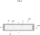
- FIG. 4 is a schematic sectional view illustrating a battery relating to another embodiment of the present disclosure. Note that the electrode body 2, the positive electrode foil and the negative electrode foil are similar to those illustrated in Fig. 1 and Fig. 2 , and description thereof is omitted.
- positive electrode metal exterior body 43 of a metal exterior body pair is formed of a metal and is disposed so as to contact the positive electrode foil.
- Negative electrode metal exterior body 44 is formed of a metal and is disposed so as to contact the negative electrode foil. At least portions of the outer surfaces of both the positive electrode metal exterior body 43 and the negative electrode metal exterior body 44 of the metal exterior body pair are exposed such that electrical connection with the exterior is enabled.
- the positive electrode metal exterior body 43 is formed in the shape of a box having a bottom plate 43A that is quadrilateral and four side plates 43B that each share one side with the bottom plate 43A.
- the positive electrode metal exterior body 43 houses the electrode body 2 at the inner side of the box shape that is formed by the bottom plate 43A and the side plates 43B.
- the negative electrode metal exterior body 44 is formed by a quadrilateral, plate-shaped member.
- the electrode body 2 and the metal exterior body pair formed by the positive electrode metal exterior body 43 and the negative electrode metal exterior body 44 are fixed by using only one type of resin 6.
- the resin 6 is interposed between the side surfaces of the electrode body 2 and the side plates 43B of the positive electrode metal exterior body 43, and the side surfaces of the electrode body 2 are covered by the resin 6.
- the side surfaces of the electrode body 2 are insulated by the resin 6 from the metal exterior body pair that is formed from the positive electrode metal exterior body 43 and the negative electrode metal exterior body 44.
- the positive electrode metal exterior body 43 and the negative electrode metal exterior body 44 are insulated by the resin 6.
- the positive electrode metal exterior body 43, the negative electrode metal exterior body 44 and the side surfaces of the electrode body 2 are respectively insulated by the resin 6. The occurrence of short-circuiting is thereby suppressed.
- the positive electrode metal exterior body and the negative electrode metal exterior body are formed of metal.
- the metal materials are aluminum, aluminum alloys, stainless steel, copper, copper alloys, nickel steel, and the like.
- the thickness of the positive electrode metal exterior body and the negative electrode metal exterior body is, for example, 0.05 mm or more and 2.0 mm or less.
- the battery 10 illustrated in Fig. 1 has the resin 6A that is interposed between the side surfaces of the electrode body 2 and the side plates 41B of the positive electrode metal exterior body 41, and the resin 6B that is interposed between the side plates 41B of the positive electrode metal exterior body 41 and the side plates 42B of the negative electrode metal exterior body 42.
- the first resin that is interposed between the side surfaces of the electrode body and the side plates of the metal exterior body at which the surface area of the bottom plate is smaller, and the second resin that is interposed between the side plates of the metal exterior body at which the surface area of the bottom plate is smaller and the side plates of the metal exterior body at which the surface area of the bottom plate is larger be different types of resin.
- the first resin and the second resin have different performances.
- the first resin be a resin whose insulating ability is better than that of the second resin
- the second resin be a resin whose moisture permeation resistance is better than that of the first resin.
- Resins having good insulating ability mean resins whose electrical resistance at the time when current passes through the resin is higher.
- Resins having good moisture permeation resistance mean resins at which the amount of water vapor per 1 m 2 unit surface area that, in a 24-hour period, passes-through a resin placed between two spaces having a difference in relative humidities, is small.
- Examples of the first resin whose insulating ability is good are polyethylene (PE), polyamide (PA), polyester (PEs), polypropylene (PP), polyetherimide (PEI), polytetrafluoroethylene (PTFE), polyurethane (TPU) and the like.
- Examples of the second resin that has good moisture permeation resistance are polyethylene (PE), polypropylene (PP), polystyrene (PS), cyclic olefin copolymer (COC) and the like.
- the electrode body usually has a collector, a positive electrode active material layer, an electrolyte layer and a negative electrode active material layer.
- the battery may have a layered-type electrode body in which plural electrode bodies are layered, or may have only one electrode body.
- the electrode body preferably is a structure in which plural bipolar electrodes are layered via solid electrolyte layers. More specifically, the electrode body is preferably a layered bipolar solid electrode body having: a bipolar electrode having a collector and electrode active material layers including a positive electrode active material layer formed on one surface of the collector and a negative electrode active material layer formed on another surface of the collector; and a solid electrolyte layer containing a solid electrolyte, and having a structure in which plural bipolar electrodes are layered via solid electrolyte layers.
- the positive electrode active material layer contains at least a positive electrode active material.
- the positive electrode active material layer may further contain at least one of a conductive material, an electrolyte and a binder.
- the shape of the positive electrode active material is particle-shaped for example. Oxide active materials are examples of the positive electrode active material. Further, sulfur (S) may be used as the positive electrode active material.
- the positive electrode active material preferably contains a lithium composite oxide.
- the lithium composite oxide contains at least one type selected from the group consisting of F, Cl, N, S, Br and I. Further, the lithium composite oxide may have a crystal structure belonging to at least one space group selected from space groups R-3m, Immm, and P63-mmc (also called P63mc, P6/mmc).
- the main sequence of a transition metal, oxygen and lithium may be an O2-type structure.
- lithium composite oxides having a crystal structure belonging to R-3m are compounds expressed by Li x Me y O ⁇ X ⁇ (Me represents at least one type selected from the group consisting of Mn, Co, Ni, Fe, Al, Cu, V, Nb, Mo, Ti, Cr, Zr, Zn, Na, K, Ca, Mg, Pt, Au, Ag, Ru, W, B, Si and P, and X represents at least one type selected from the group consisting of F, Cl, N, S, Br and I, and 0.5 ⁇ x ⁇ 1.5, 0.5 ⁇ y ⁇ 1.0, 1 ⁇ 2, 0 ⁇ 1 are satisfied).
- lithium composite oxides having a crystal structure belonging to Immm are composite oxides expressed by Li x1 M 1 A 1 2 (1.5 ⁇ x1 ⁇ 2.3 is satisfied, M 1 includes at least one type selected from the group consisting of Ni, Co, Mn, Cu and Fe, A 1 includes at least oxygen, and the ratio of the oxygen contained in A 1 is greater than or equal to 85 atom%) (a specific example is Li 2 NiO 2 ), and composite oxides expressed by Li x1 M 1A 1-x2 M 1B x2 O 2-y A 2 y (0 ⁇ x2 ⁇ 0.5 and 0 ⁇ y ⁇ 0.3, at least one of x2 and y is not 0, M 1A represents at least one type selected from the group consisting of Ni, Co, Mn, Cu and Fe, M 1B represents at least one type selected from the group consisting of Al, Mg, Sc, Ti, Cr, V, Zn, Ga, Zr, Mo, Nb, Ta and W, and A2 represents at least one type selected from the group consisting of F, Cl, Br, S and P
- lithium composite oxides having a crystal structure belonging to P63-mmc are composite oxides expressed by M1 x M2 y O 2 (M1 represents an alkali metal (at least one of Na and K is preferable), M2 represents a transition metal (at least one type selected from the group consisting of Mn, Ni, Co and Fe is preferable), and x+y satisfies 0 ⁇ x+y ⁇ 2).
- M1 represents an alkali metal (at least one of Na and K is preferable)
- M2 represents a transition metal (at least one type selected from the group consisting of Mn, Ni, Co and Fe is preferable)
- x+y satisfies 0 ⁇ x+y ⁇ 2).
- lithium composite oxides having an O2-type structure are composite oxides expressed by Li x [Li ⁇ (Mn a Co b M c ) 1- ⁇ ]O 2 (0.5 ⁇ x ⁇ 1.1, 0.1 ⁇ 0.33, 0.17 ⁇ a ⁇ 0.93, 0.03 ⁇ b ⁇ 0.50, 0.04 ⁇ c ⁇ 0.33, and M represents at least one type selected from the group consisting of Ni, Mg, Ti, Fe, Sn, Zr, Nb, Mo, W and Bi). Specific examples are Li 0.744 [Li 0.145 Mn 0.625 Co 0.115 Ni 0.115 ]O 2 and the like.
- the positive electrode preferably contains a solid electrolyte selected from the group of solid electrolytes consisting of sulfide solid electrolytes, oxide solid electrolytes, and halide solid electrolytes.
- a solid electrolyte selected from the group of solid electrolytes consisting of sulfide solid electrolytes, oxide solid electrolytes, and halide solid electrolytes.
- a form in which at least a portion of the surface of the positive electrode active material is covered by a sulfide solid electrolyte, an oxide solid electrolyte or a halide solid electrolyte is more preferable.
- Li 6-(4-x)b (Ti 1-x Al x ) b F 6 (0 ⁇ x ⁇ 1, 0 ⁇ b ⁇ 1.5) [LTAF electrolyte] is preferable as the halide solid electrolyte that covers at least a portion of the surface of the positive electrode active material.
- the electrolyte may be a solid electrolyte or may be a liquid electrolyte, but a solid electrolyte is preferable.
- the solid electrolyte may be an organic solid electrolyte such as a gel electrolyte or the like, or may be an inorganic solid electrolyte such as an oxide solid electrolyte, a sulfide solid electrolyte or the like.
- Liquid electrolytes include, for example, supporting salts such as LiPF 6 and the like, and solvents such as carbonate solvents and the like.
- examples of the binder are rubber binders and fluoride binders.
- the negative electrode active material layer contains at least a negative electrode active material.
- the negative electrode active material layer may further contain at least one of a conductive material, an electrolyte, and a binder.
- a conductive material such as Li, Si and the like
- carbon active materials such as graphite and the like
- oxide active materials such as Li 4 Ti 5 O 12 and the like.
- the shape of the negative electrode active material is, for example, particulate-shaped or foil-shaped.
- the conductive material, the electrolyte and the binder are similar to those described above.
- the electrolyte layer is disposed between the positive electrode active material layer and the negative electrode active material layer, and contains at least an electrolyte.
- the electrolyte may be a solid electrolyte or may be a liquid electrolyte. It is preferable that the electrolyte layer be a solid electrolyte layer.
- the electrolyte layer may have a separator.
- the solid electrolyte preferably includes at least one type of solid electrolyte selected from the group of solid electrolytes consisting of sulfide solid electrolytes, oxide solid electrolytes and halide solid electrolytes.
- the sulfide solid electrolyte preferably contains sulfur (S) as the main component that is an anion element, and further, preferably contains, for example, the element Li, element A and the element S.
- Element A is at least one type selected from the group consisting of P, As, Sb, Si, Ge, Sn, B, Al, Ga and In.
- the sulfide solid electrolyte may further contain at least one of O and a halogen element. Examples of the halogen element (X) are F, Cl, Br, I and the like.
- the composition of the sulfide solid electrolyte is not particularly limited, and examples are xLi 2 S•(100-x)P 2 S 5 (70 ⁇ x ⁇ 80) and yLiI•zLiBr•(100-y-z)(xLi 2 S•(1-x)P 2 S 5 ) (0.7 ⁇ x ⁇ 0.8, 0 ⁇ y ⁇ 30, 0 ⁇ z ⁇ 30).
- the sulfide solid electrolyte may have the composition expressed by following general formula (1). Li 4-x Ge 1-x P x S 4 (0 ⁇ x ⁇ 1) ...
- At least a portion of Ge may be substituted by at least one selected from the group consisting of Sb, Si, Sn, B, Al, Ga, In, Ti, Zr, V and Nb.
- at least a portion of P may be substituted by at least one selected from the group consisting of Sb, Si, Sn, B, Al, Ga, In, Ti, Zr, V and Nb.
- a portion of Li may be substituted by at least one selected from the group consisting of Na, K, Mg, Ca and Zn.
- a portion of S may be substituted by a halogen.
- the halogen is at least one of F, Cl, Br and I.
- the oxide solid electrolyte preferably contains oxygen (O) as the main component that is an anion element, and, for example, may contain Li, element Q (Q represents at least one of Nb, B, Al, Si, P, Ti, Zr, Mo, W and S), and O.
- O oxygen
- Examples of the oxide solid electrolyte are garnet type solid electrolytes, perovskite type solid electrolytes, NASICON type solid electrolytes, Li-P-O solid electrolytes, Li-B-O solid electrolytes, and the like.
- garnet type solid electrolytes are Li 7 La 3 Zr 2 O 12 , Li 7-x La 3 (Zr 2-x Nb x )O 12 (0 ⁇ x ⁇ 2), Li 5 La 3 Nb 2 O 12 , and the like.
- Examples of perovskite type solid electrolytes are (Li,La)TiO 3 , (Li,La)NbO 3 , (Li,Sr)(Ta,Zr)O 3 and the like.
- Examples of NASICON type solid electrolytes are Li(Al,Ti)(PO 4 ) 3 , Li(Al,Ga)(PO 4 ) 3 , and the like.
- Examples of Li-P-O solid electrolytes are Li 3 PO 4 and LIPON (compounds in which some of the O in Li 3 PO 4 is substituted with N).
- Examples of Li-B-O solid electrolytes are Li 3 BO 3 , compounds in which some of the O in Li 3 BO 3 is substituted with C, and the like.
- solid electrolytes containing Li, M and X (M represents at least one of Ti, Al and Y, and X represents F, Cl or Br) are suitable.
- Li 6-3z Y z X 6 (X represents Cl or Br, and z satisfies 0 ⁇ z ⁇ 2) and Li 6-(4-x)b (Ti 1-x Al x ) b F 6 (0 ⁇ x ⁇ 1, 0 ⁇ b ⁇ 1.5) are preferable.
- Li 6-3z Y z X 6 from the standpoint of having excellent lithium ion conductivity, Li 3 YX 6 (X represents Cl or Br) is more preferable, and Li 3 YCl 6 is even more preferable.
- Li 6-(4-x)b (Ti 1-x Al x ) b F 6 (0 ⁇ x ⁇ 1, 0 ⁇ b ⁇ 1.5) be contained together with a solid electrolyte such as a sulfide solid electrolyte or the like.
- a collector that is electrically conductive and that can form a positive electrode active material layer and a negative electrode active material layer is used.
- Examples are stainless steel, aluminum, nickel, iron, titanium, carbon, copper and the like.
- the form of the collector is, for example, the form of a foil or the form of a mesh.
- the electrode body may have a structure in which a positive electrode collector, a positive electrode active material layer, an electrolyte layer, a negative electrode active material layer and a negative electrode collector are layered in that order.
- the positive electrode collector carries out power collection of the positive electrode active material layer.
- the positive electrode collector are stainless steel, aluminum, nickel, iron, titanium, carbon and the like, and an aluminum alloy foil or an aluminum foil is preferable.
- the aluminum alloy foil or aluminum foil may be manufactured by using a powder.
- Examples of the form of the positive electrode collector are the form of a foil and the form of a mesh.
- the positive electrode collector may have a positive electrode tab for connection with a positive electrode collector terminal.
- the negative electrode collector carries out power collection of the negative electrode active material layer.
- Examples of the material of the negative electrode collector are metals such as copper, SUS, nickel and the like. Examples of the form of the negative electrode collector are the form of a foil and the form of a mesh.
- the negative electrode collector may have a negative electrode tab for connection with a negative electrode collector terminal.
- a positive electrode foil is provided at the surface, which is at the positive electrode side, of the electrode body.
- a negative electrode foil is provided at the surface, which is at the negative electrode side.
- Examples of the positive electrode foil are stainless steel, aluminum, nickel, iron, titanium, carbon and the like.
- Examples of the negative electrode foil are copper, SUS, nickel and the like.
- the battery of the present disclosure is preferably a solid-state battery.
- Solid-state batteries include so-called all-solid-state batteries that use an inorganic solid electrolyte as the electrolyte (batteries using a solid electrolyte and not using an electrolytic liquid).
- the structure of the solid-state battery is a layered structure of a positive electrode / a solid electrolyte layer / a negative electrode.
- the positive electrode has a positive electrode active material layer and a collector.
- the negative electrode has a negative electrode active material layer and a collector.
- the solid electrolyte layer may be a single layer structure, or may be a multilayer structure of two or more layers.
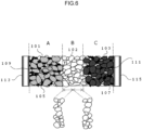
- the solid-state battery may have the cross-sectional structure illustrated in Fig. 6
- solid electrolyte layer B may be a two-layer structure as illustrated in Fig. 6.
- Fig. 6 is a schematic sectional view illustrating an example of a solid-state battery.
- the solid-state battery illustrated in Fig. 6 has a negative electrode including a negative electrode collector 113 and a negative electrode active material layer A, and the solid electrolyte layer B, and a positive electrode including a positive electrode collector 115 and positive electrode active material layer C.
- the negative electrode active material layer A includes a negative electrode active material 101, a conduction assistant 105 and a binder 109.
- the positive electrode active material layer C includes a covered positive electrode active material 103, a conduction assistant 107 and a binder 111.
- the covered positive electrode active material 103 the surface of a positive electrode active material is covered by an LTAF electrolyte or an LiNbO 3 electrolyte.
- the solid-state battery may be structured such that the layer end surfaces (side surfaces) of a layered structure of a positive electrode / a solid electrolyte layer / a negative electrode are sealed by a resin.
- the collector of the electrode may be a structure in which a shock-absorbing layer, an elastic layer or a PTC (Positive Temperature Coefficient) thermistor layer is disposed on the surface of the collector.
- An example of the intended use of the battery is the power source of a vehicle such as, for example, a hybrid vehicle (HEV), a plug-in hybrid vehicle (PHEV), an electric vehicle (BEV), a gasoline-powered vehicle, a diesel-powered vehicle or the like.
- the battery is particularly preferably used as the power source for driving of an HEV, a PHEV or a BEV.
- the battery of the present disclosure may be used as the power source of a moving body other than a vehicle (e.g., a train, a boat, an airplane), or may be used as the power source of an electronic product such as an information processing device or the like.
Landscapes
- Chemical & Material Sciences (AREA)
- Chemical Kinetics & Catalysis (AREA)
- Electrochemistry (AREA)
- General Chemical & Material Sciences (AREA)
- Engineering & Computer Science (AREA)
- Manufacturing & Machinery (AREA)
- Inorganic Chemistry (AREA)
- Architecture (AREA)
- Civil Engineering (AREA)
- Structural Engineering (AREA)
- Materials Engineering (AREA)
- Sealing Battery Cases Or Jackets (AREA)
Abstract
A battery has: an electrode body; a positive electrode foil and a negative electrode foil provided at surfaces of the electrode body; a metal exterior body pair formed from a positive electrode metal exterior body that contacts the positive electrode foil and a negative electrode metal exterior body that contacts the negative electrode foil; and resins that fix the electrode body and the metal exterior body pair. Outer surfaces of the metal exterior body pair are exposed so as to enable electrical connection with an exterior. At least one of the positive electrode metal exterior body or the negative electrode metal exterior body is shaped as a box having a bottom plate that is quadrilateral and four side plates that each share one side with the bottom plate, and accommodates the electrode body at an inner side of the box shape. The positive electrode metal exterior body, the negative electrode metal exterior body, and side surfaces of the electrode body are respectively insulated by the resins.
Description
- The present disclosure relates to a battery.
- Conventionally, batteries in which an electrode body is sealed by a laminate film that serves as an exterior body have been used from the standpoints of battery strength and of suppressing permeation of water vapor into the interior of the battery.
For example, Japanese Patent Application Laid-Open (JP-A) No. 2021-150073 - On the other hand, batteries in which the electrode body is sealed by an exterior body that is not a laminate film also have been disclosed.
For example,JP-A No. 2017-220447 - Further, International Publication No.
2021/149644 discloses a secondary battery formed to have an electrode assembly and an exterior body that houses the electrode assembly. The exterior body is formed to have a two-part structure of a first metal exterior body and a second metal exterior body. The first metal exterior body and the second metal exterior body that are metal members are assembled together without being caulked. - In a conventional battery, a laminate film for example is used as the exterior body. However, in order for the laminate film to exhibit moisture permeation resistance (i.e., water vapor barrier performance), the surface area of the region where the end portions of the laminate film are thermally welded must be made to be large. The structural efficiency of the battery thereby deteriorates. Further, a terminal for external connection must be exposed to the exterior of the laminate film from a side surface side of the electrode body, and the structural efficiency deteriorates for this reason as well.
- The present disclosure was made in view of the above-described circumstances, and an object thereof is to provide a battery that maintains moisture permeation resistance and has good structural efficiency.
- A battery of a first aspect of the present disclosure including:
- an electrode body;
- a positive electrode foil provided at one surface of the electrode body;
- a negative electrode foil provided at another surface of the electrode body;
- a metal exterior body pair formed from a positive electrode metal exterior body that contacts the positive electrode foil and is formed of metal, and a negative electrode metal exterior body that contacts the negative electrode foil and is formed of metal; and
- a resin that fixes the electrode body and the metal exterior body pair,
- wherein outer surfaces of the metal exterior body pair are exposed so as to enable electrical connection with an exterior,
- wherein at least one of the positive electrode metal exterior body or the negative electrode metal exterior body is shaped as a box having a bottom plate that is quadrilateral and four side plates that each share one side with the bottom plate, and accommodates the electrode body at an inner side of the box shape, and
- wherein the positive electrode metal exterior body, the negative electrode metal exterior body, and side surfaces of the electrode body are respectively insulated by the resin.
- A battery of a second aspect according to the present disclosure is the battery of the first aspect, wherein:
- the positive electrode metal exterior body and the negative electrode metal exterior body are both box shaped,
- the positive electrode metal exterior body and the negative electrode metal exterior body overlap such that sides of the positive electrode metal exterior body and the negative electrode metal exterior body having the side plates face one another, and
- a surface area of one of the bottom plate of the positive electrode metal exterior body or the bottom plate of the negative electrode metal exterior body is larger than another, and all of the side plates of the metal exterior body at which a surface area of the bottom plate is smaller are accommodated at inner sides of all of the side plates of the metal exterior body at which a surface area of the bottom plate is larger.
- A battery of a third aspect according to the present disclosure is the battery of the second aspect, wherein:
- the battery has, as the resin, a first resin that is interposed between the side surfaces of the electrode body and the side plates of the metal exterior body at which the surface area of the bottom plate is smaller, and a second resin that is interposed between the side plates of the metal exterior body at which the surface area of the bottom plate is smaller and the side plates of the metal exterior body at which the surface area of the bottom plate is larger,
- the first resin is a resin that has a better insulating ability than the second resin, and
- the second resin is a resin that has better moisture permeation resistance than the first resin.
- A battery of a fourth aspect according to the present disclosure is the battery of the second aspect or the third aspect, wherein the metal exterior body at which the surface area of the bottom plate is larger is the negative electrode metal exterior body.
- A battery of a fifth aspect according to the present disclosure is the battery of any one of the second aspect to the fourth aspect, wherein:
- the resin is filled-in between the side surfaces of the electrode body and the side plates of the metal exterior body at which the surface area of the bottom plate is smaller, and between the side plates of the metal exterior body at which the surface area of the bottom plate is smaller and the side plates of the metal exterior body at which the surface area of the bottom plate is larger,
- a distance from the side plate of the metal exterior body at which the surface area of the bottom plate is smaller to the side plate of the metal exterior body at which the surface area of the bottom plate is larger is from 0.1 mm to 1.0 mm, and
- a distance in a thickness direction of the electrode body from an end, which is at a side opposite the bottom plate, at the side plate of the metal exterior body at which the surface area of the bottom plate is smaller to an end, which is at the side opposite the bottom plate, at the side plate of the metal exterior body at which the surface area of the bottom plate is larger is from 1.0 mm to 50.0 mm.
- A battery of a sixth aspect according to the present disclosure is the battery of any one of the first aspect to the fifth aspect, wherein the battery is a solid-state battery.
- A battery of a seventh aspect according to the present disclosure is the battery of any one of the first aspect to the sixth aspect, wherein, at the electrode body, plural bipolar electrodes are layered via solid electrolyte layers.
- In accordance with the present disclosure, there can be provided a battery that maintains moisture permeation resistance and has good structural efficiency.
-
-
Fig. 1 is a schematic sectional view illustrating a battery relating to an embodiment of the present disclosure; -
Fig. 2 is a schematic perspective view illustrating an electrode body, a positive electrode foil and a negative electrode foil of the battery relating to the embodiment of the present disclosure; -
Fig. 3 is a schematic perspective view illustrating a positive electrode metal exterior body and a negative electrode metal exterior body of the battery relating to the embodiment of the present disclosure; -
Fig. 4 is a schematic sectional view illustrating a battery relating to another embodiment of the present disclosure; -
Fig. 5 is a schematic sectional view illustrating a conventional battery that uses a laminate sheet as an exterior body; -
Fig. 6 is a schematic sectional view illustrating an example of a solid-state battery; and -
Fig. 7 is a graph illustrating the relationship between length of a sealing portion, thickness of a sealing portion, and an amount of moisture permeation. - A battery of the present disclosure is described in detail hereinafter by using the drawings. The respective drawings described hereinafter are schematic illustrations, and sizes and shapes of respective portions are exaggerated when appropriate in order to facilitate understanding.
-
Fig. 1 is a schematic sectional view illustrating a battery relating to an embodiment of the present disclosure.Fig. 2 is a schematic perspective view illustrating an electrode body, a positive electrode foil and a negative electrode foil of the battery relating to the embodiment of the present disclosure. Abattery 10 relating to the present disclosure has anelectrode body 2, a metal exterior body pair formed from a positive electrode metalexterior body 41 and a negative electrode metalexterior body 42, andresins Fig. 2 , the battery has apositive electrode foil 2A, which is provided between theelectrode body 2 and the positive electrode metalexterior body 41 so as to contact the positive electrode side surface of theelectrode body 2, and anegative electrode foil 2B, which is provided between theelectrode body 2 and the negative electrode metalexterior body 42 so as to contact the negative electrode side surface of theelectrode body 2. (Thepositive electrode foil 2A and thenegative electrode foil 2B are omitted inFig. 1 .) -
Fig. 3 is a schematic perspective view illustrating only the positive electrode metalexterior body 41 and the negative electrode metalexterior body 42 of the battery relating to the embodiment of the present disclosure. - The positive electrode
metal exterior body 41 at the metal exterior body pair is formed of metal, and is disposed so as to contact thepositive electrode foil 2A. The negative electrodemetal exterior body 42 is formed of metal, and is disposed so as to contact thenegative electrode foil 2B. At least portions of the outer surfaces of the positive electrodemetal exterior body 41 and the negative electrodemetal exterior body 42 of the metal exterior body pair are exposed to as to enable electrical connection with the exterior. As illustrated inFig. 1 andFig. 3 , the positive electrodemetal exterior body 41 is formed in the shape of a box having abottom plate 41A that is quadrilateral and fourside plates 41B that each share one side with thebottom plate 41A. The positive electrodemetal exterior body 41 houses theelectrode body 2 at the inner side of the box shape that is formed by thebottom plate 41A and theside plates 41B. The negative electrodemetal exterior body 42 is formed in the shape of a box having abottom plate 42A that is quadrilateral and fourside plates 42B that each share one side with thebottom plate 42A. The negative electrodemetal exterior body 42 houses theelectrode body 2 at the inner side of the box shape that is formed by thebottom plate 42A and theside plates 42B. The positive electrodemetal exterior body 41 and the negative electrodemetal exterior body 42 are superposed such that the sides having theside plates 41B and the sides having theside plates 42B face one another. The surface area of thebottom plate 42A at the negative electrodemetal exterior body 42 is larger than that of thebottom plate 41A at the positive electrodemetal exterior body 41, and all of theside plates 41B of the positive electrodemetal exterior body 41 are accommodated at the inner sides of all of theside plates 42B of the negative electrodemetal exterior body 42. - As illustrated in
Fig. 1 , theresins electrode body 2 and the metal exterior body pair that is formed from the positive electrodemetal exterior body 41 and the negative electrodemetal exterior body 42. Theresin 6A is interposed between the side surfaces of theelectrode body 2 and theside plates 41B of the positive electrodemetal exterior body 41, and the side surfaces of theelectrode body 2 are covered by theresin 6A. Theresin 6B is interposed between theside plates 41B of the positive electrodemetal exterior body 41 and theside plates 42B of the negative electrodemetal exterior body 42. The side surfaces of theelectrode body 2 are insulated from the metal exterior body pair, which is formed from the positive electrodemetal exterior body 41 and the negative electrodemetal exterior body 42, by theresins metal exterior body 41 and the negative electrodemetal exterior body 42 are insulated by theresins metal exterior body 41, the negative electrodemetal exterior body 42 and the side surfaces of theelectrode body 2 are respectively insulated by theresins - In a conventional battery, for example, a laminate film is used as the exterior body. For example, one laminate film is folded-over and covers the electrode body, and one end side and the another end side of the laminate film are superposed together and are sealed by heat welding. Further, as illustrated in
Fig. 5 , there is also the example of abattery 20 in which twolaminate films electrode body 22 that hasterminals 28, and thebattery 20 is sealed due to the end portions of the twolaminate films
Further, in a case of using laminate films as the exterior body, the terminals for external connection (the positive electrode terminal and the negative electrode terminal) must be exposed to the exterior of the laminate films from the side surface sides of the electrode body, and for this reason as well, the structural efficiency deteriorates. - In contrast, the battery relating to the present disclosure uses the metal exterior body, which is formed from the positive electrode metal exterior body and the negative electrode metal exterior body, as the exterior body instead of a laminate film, and the electrode body and the metal exterior body pair are fixed by resins. Further, one or both of the positive electrode metal exterior body and the negative electrode metal exterior body is shaped as a box having a bottom plate that is quadrilateral and four side plates that each share one side with the bottom plate, and accommodates the electrode body at the inner side of the box shape. Due to the electrode body and the metal exterior body pair being fixed and made integral by the resins, and at least one of the metal exterior body pair being formed in the shape of a box, the strength and the moisture permeation resistance (water vapor barrier ability) that are required of a battery can be ensured. Further, because there is no need for a heat-welded region (a sealed portion) that is necessary in a case in which a laminate film is used, the structural efficiency can be improved.
- The positive electrode metal exterior body and the negative electrode metal exterior body are formed of metal. The positive electrode metal exterior body contacts the positive electrode foil, and the negative electrode metal exterior body contacts the negative electrode foil. Moreover, at least a portion of the outer surface of each of the positive electrode metal exterior body and the negative electrode metal exterior body is exposed so as to enable electrical connection with the exterior. Due thereto, the positive electrode metal exterior body and the negative electrode metal exterior body can be made to function as terminals. In other words, the positive electrode and the negative electrode at the electrode body can be electrically connected to the exterior through the positive electrode metal exterior body and the negative electrode metal exterior body, respectively. Therefore, the providing of terminals that are exposed to the exterior from the side surface sides of the electrode body, which is necessary in a case of using a laminate film, becomes unnecessary, and the structural efficiency can be improved for this reason as well.
- Due to the above, in accordance with the battery relating to the present disclosure, the moisture permeation resistance can be maintained and the structural efficiency of the battery can be improved.
- In the
battery 10 illustrated inFig. 1 andFig. 3 , the metal exterior body at which the surface area of the bottom plate is larger is the negative electrodemetal exterior body 42. In this way, in the battery relating to the present disclosure, the metal exterior body at which the surface area of the bottom plate is larger can be made to be the negative electrode metal exterior body, from the standpoint of preventing short-circuiting. - In the
battery 10 illustrated inFig. 1 andFig. 3 , the surface area of thebottom plate 42A at the negative electrodemetal exterior body 42 is larger than that of thebottom plate 41A at the positive electrodemetal exterior body 41, and all of theside plates 41B at the positive electrodemetal exterior body 41 are accommodated at the inner sides of all of theside plates 42B at the negative electrodemetal exterior body 42. In this way, in the battery relating to the present disclosure, there is preferably a structure in which the surface area of one of the bottom plate at the positive electrode metal exterior body and the bottom plate at the negative electrode metal exterior body is larger than the other, and all of the side plates of the metal exterior body at which the surface area of the bottom plate is smaller are accommodated at the inner sides of all of the side plates of the metal exterior body at which the surface area of the bottom plate is larger. This structure is a structure in which the outer sides of the side surfaces of the electrode body are covered doubly by metal exterior bodies, by the side plates of the metal exterior body at which the surface area of the bottom plate is smaller and the side plates of the metal exterior body at which the surface area of the bottom plate is larger. Due thereto, in relation to the resin that covers the side surfaces of the electrode body, the distance from the side surface of the electrode body to the place where the resin is exposed to the exterior of the battery can be made to be long, and the moisture permeation resistance (water vapor barrier ability) can be improved. Further, the strength of the side surface sides of the electrode body can be improved. - At the
battery 10 illustrated inFig. 1 , theresins electrode body 2 and theside plates 41B at the positive electrodemetal exterior body 41, and between theside plates 41B at the positive electrodemetal exterior body 41 and theside plates 42B at the negative electrodemetal exterior body 42. In a case in which, in this way, resins are filled-in between the side surfaces of the electrode body and the side plates of the metal exterior body at which the surface area of the bottom plate is smaller, and between the side plates of the metal exterior body at which the surface area of the bottom plate is smaller and the side plates of the metal exterior body at which the surface area of the bottom plate is larger, the lengths of the resins at respective places are preferably the following lengths. - The distance from a side plate of the metal exterior body at which the surface area of the bottom plate is smaller to a side plate of the metal exterior body at which the surface area of the bottom plate is larger (e.g., in the
battery 10 illustrated inFig. 1 , distance L1 from theside plate 41B at the positive electrodemetal exterior body 41 to theside plate 42B at the negative electrode metal exterior body 42) is preferably 0.1 mm or more and 1.0 mm or less. Due to the distance being 0.1 mm or more, it is even easier to suppress short-circuiting between the metal exterior bodies. On the other hand, due to the distance being 1.0 mm or less, the structural efficiency of the battery can be improved more, and the moisture permeation resistance (water vapor barrier ability) can be improved more. The aforementioned distance (distance L1 inFig. 1 ) is even more preferably 0.3 mm or more and 0.7 mm or less. - Note that the distance between a side plate of the metal exterior body at which the surface area of the bottom plate is smaller and a side plate of the metal exterior body at which the surface area of the bottom plate is larger is measured at five arbitrary places of each of the four side plates of the metal exterior bodies (a total of 20 places), and the average value thereof is used as the aforementioned distance (distance L1 in
Fig. 1 ). - The distance in the thickness direction of the electrode body from the end, which is at the side opposite the bottom plate, at a side plate of the metal exterior body at which the surface area of the bottom plate is smaller to the end, which is at the side opposite the bottom plate, at a side plate of the metal exterior body at which the surface area of the bottom plate is larger (e.g., in the
battery 10 illustrated inFig. 1 , distance L2 in the thickness direction of the electrode body 2 (i.e., the up-down direction inFig. 1 ) from the end, which is at the side opposite thebottom plate 41A, of theside plate 41B of the positive electrodemetal exterior body 41 to the end, which is at the side opposite thebottom plate 42A, of theside plate 42B of the negative electrode metal exterior body 42) is preferably 1.0 mm or more and 50.0 mm or less. Due to the distance being 1.0 mm or more, the moisture permeation resistance (water vapor barrier ability) can be improved more. On the other hand, due to the distance being 50.0 mm or less, poor filling of the resins can be prevented. The aforementioned distance (distance L2 inFig. 1 ) is more preferably 2.0 mm or more and 10.0 mm or less. - Note that the distance, in the thickness direction of the electrode body, from the end, which is at the side opposite the bottom plate, of a side plate of the metal exterior body at which the surface area of the bottom plate is smaller to the end, which is at the side opposite the bottom plate, of a side plate of the metal exterior body at which the surface area of the bottom plate is larger is measured at five arbitrary places of each of the four side plates of the metal exterior bodies (a total of 20 places), and the average value thereof is used as the aforementioned distance (distance L2 in
Fig. 1 ). - Note that moisture was made to permeate through an evaluation sample of the resin for a given time period, and a permeation factor of the moisture at the resin was measured, and the results of calculating the permeation amount by the following calculation formula (i.e., a graph) are shown in
Fig. 7 . Note that a thermoplastic resin was used as the resin of the evaluation sample.
Fig. 1 ) in the thickness direction of the electrode body from the end, which is at the side opposite the bottom plate, of a side plate of the metal exterior body at which the surface area of the bottom plate is smaller to the end, which is at the side opposite the bottom plate, of a side plate of the metal exterior body at which the surface area of the bottom plate is larger, S represents the sectional surface area of permeation, and RH represents the relative humidity.) - As illustrated in
Fig. 7 , it can be understood that, the shorter the distance from a side plate of the metal exterior body at which the surface area of the bottom plate is smaller to a side plate of the metal exterior body at which the surface area of the bottom plate is larger (distance L1 inFig. 1 , called "sealing portion thickness" inFig. 7 ), the more that permeation of moisture is suppressed. Further, it can be understood that, the longer the distance, in the thickness direction of the electrode body, from the end, which is at the side opposite the bottom plate, of a side plate of the metal exterior body at which the surface area of the bottom plate is smaller to the end, which is at the side opposite the bottom plate, of a side plate of the metal exterior body at which the surface area of the bottom plate is larger (distance L2 inFig. 1 , called "sealing portion length" inFig. 7 ), the more that permeation of moisture is suppressed. - An aspect has been described in which, in the
battery 10 illustrated inFig. 1 andFig. 3 , both the positive electrodemetal exterior body 41 and the negative electrodemetal exterior body 42 are box-shaped, and the surface area of thebottom plate 42A at the negative electrodemetal exterior body 42 is larger than that of thebottom plate 41A at the positive electrodemetal exterior body 41, and all of theside plates 41B of the positive electrodemetal exterior body 41 are accommodated at the inner sides of all of theside plates 42B of the negative electrodemetal exterior body 42. However, the present disclosure is not limited to this, and, in the battery relating to the present disclosure, it suffices for at least one of the positive electrode metal exterior body or the negative electrode metal exterior body to be shaped as a box. - A battery relating to another embodiment of the present disclosure is described here.
Fig. 4 is a schematic sectional view illustrating a battery relating to another embodiment of the present disclosure. Note that theelectrode body 2, the positive electrode foil and the negative electrode foil are similar to those illustrated inFig. 1 andFig. 2 , and description thereof is omitted. - In
battery 10B illustrated inFig. 4 , positive electrodemetal exterior body 43 of a metal exterior body pair is formed of a metal and is disposed so as to contact the positive electrode foil. Negative electrodemetal exterior body 44 is formed of a metal and is disposed so as to contact the negative electrode foil. At least portions of the outer surfaces of both the positive electrodemetal exterior body 43 and the negative electrodemetal exterior body 44 of the metal exterior body pair are exposed such that electrical connection with the exterior is enabled. As illustrated inFig. 4 , the positive electrodemetal exterior body 43 is formed in the shape of a box having abottom plate 43A that is quadrilateral and fourside plates 43B that each share one side with thebottom plate 43A. The positive electrodemetal exterior body 43 houses theelectrode body 2 at the inner side of the box shape that is formed by thebottom plate 43A and theside plates 43B. The negative electrodemetal exterior body 44 is formed by a quadrilateral, plate-shaped member. - At the
battery 10B illustrated inFig. 4 , theelectrode body 2 and the metal exterior body pair formed by the positive electrodemetal exterior body 43 and the negative electrodemetal exterior body 44 are fixed by using only one type ofresin 6. Theresin 6 is interposed between the side surfaces of theelectrode body 2 and theside plates 43B of the positive electrodemetal exterior body 43, and the side surfaces of theelectrode body 2 are covered by theresin 6. The side surfaces of theelectrode body 2 are insulated by theresin 6 from the metal exterior body pair that is formed from the positive electrodemetal exterior body 43 and the negative electrodemetal exterior body 44. Further, the positive electrodemetal exterior body 43 and the negative electrodemetal exterior body 44 are insulated by theresin 6. The positive electrodemetal exterior body 43, the negative electrodemetal exterior body 44 and the side surfaces of theelectrode body 2 are respectively insulated by theresin 6. The occurrence of short-circuiting is thereby suppressed. - Even in a case in which only one of the positive electrode metal exterior body and the negative electrode metal exterior body is formed in the shape of a box as in the
battery 10B illustrated inFig. 4 , the strength and the moisture permeation resistance (water vapor barrier ability) required of the battery can be ensured, and the structural efficiency can be improved. - The respective members that structure the battery relating to the present disclosure are described next.
- The positive electrode metal exterior body and the negative electrode metal exterior body are formed of metal. Examples of the metal materials are aluminum, aluminum alloys, stainless steel, copper, copper alloys, nickel steel, and the like.
- The thickness of the positive electrode metal exterior body and the negative electrode metal exterior body is, for example, 0.05 mm or more and 2.0 mm or less.
- The
battery 10 illustrated inFig. 1 has theresin 6A that is interposed between the side surfaces of theelectrode body 2 and theside plates 41B of the positive electrodemetal exterior body 41, and theresin 6B that is interposed between theside plates 41B of the positive electrodemetal exterior body 41 and theside plates 42B of the negative electrodemetal exterior body 42. In this way, at the battery relating to the present disclosure, it is preferable that the first resin that is interposed between the side surfaces of the electrode body and the side plates of the metal exterior body at which the surface area of the bottom plate is smaller, and the second resin that is interposed between the side plates of the metal exterior body at which the surface area of the bottom plate is smaller and the side plates of the metal exterior body at which the surface area of the bottom plate is larger, be different types of resin. - Further, it is preferable that the first resin and the second resin have different performances.
- Namely, it is preferable that the first resin be a resin whose insulating ability is better than that of the second resin, and that the second resin be a resin whose moisture permeation resistance is better than that of the first resin. Owing to this structure, the insulating ability between the side surfaces of the electrode body and the metal exterior body pair can be improved by the first resin that has a good insulating ability, and the moisture permeation resistance (water vapor barrier ability) of the battery can be improved by the second resin that has good moisture permeation resistance.
- Resins having good insulating ability mean resins whose electrical resistance at the time when current passes through the resin is higher.
- Resins having good moisture permeation resistance mean resins at which the amount of water vapor per 1 m2 unit surface area that, in a 24-hour period, passes-through a resin placed between two spaces having a difference in relative humidities, is small.
- Examples of the first resin whose insulating ability is good are polyethylene (PE), polyamide (PA), polyester (PEs), polypropylene (PP), polyetherimide (PEI), polytetrafluoroethylene (PTFE), polyurethane (TPU) and the like.
Examples of the second resin that has good moisture permeation resistance are polyethylene (PE), polypropylene (PP), polystyrene (PS), cyclic olefin copolymer (COC) and the like. - Note that, in a case in which only one type of resin is used in the battery, the resins exemplified above can be used.
- The electrode body usually has a collector, a positive electrode active material layer, an electrolyte layer and a negative electrode active material layer. In the present disclosure, the battery may have a layered-type electrode body in which plural electrode bodies are layered, or may have only one electrode body.
- Note that the electrode body preferably is a structure in which plural bipolar electrodes are layered via solid electrolyte layers. More specifically, the electrode body is preferably a layered bipolar solid electrode body having: a bipolar electrode having a collector and electrode active material layers including a positive electrode active material layer formed on one surface of the collector and a negative electrode active material layer formed on another surface of the collector; and a solid electrolyte layer containing a solid electrolyte, and having a structure in which plural bipolar electrodes are layered via solid electrolyte layers.
- The positive electrode active material layer contains at least a positive electrode active material. The positive electrode active material layer may further contain at least one of a conductive material, an electrolyte and a binder. The shape of the positive electrode active material is particle-shaped for example. Oxide active materials are examples of the positive electrode active material. Further, sulfur (S) may be used as the positive electrode active material.
- The positive electrode active material preferably contains a lithium composite oxide. The lithium composite oxide contains at least one type selected from the group consisting of F, Cl, N, S, Br and I. Further, the lithium composite oxide may have a crystal structure belonging to at least one space group selected from space groups R-3m, Immm, and P63-mmc (also called P63mc, P6/mmc). In the lithium composite oxide, the main sequence of a transition metal, oxygen and lithium may be an O2-type structure.
- Examples of lithium composite oxides having a crystal structure belonging to R-3m are compounds expressed by LixMeyOαXβ (Me represents at least one type selected from the group consisting of Mn, Co, Ni, Fe, Al, Cu, V, Nb, Mo, Ti, Cr, Zr, Zn, Na, K, Ca, Mg, Pt, Au, Ag, Ru, W, B, Si and P, and X represents at least one type selected from the group consisting of F, Cl, N, S, Br and I, and 0.5<x<1.5, 0.5≤y≤1.0, 1≤α<2, 0<β≤1 are satisfied).
- Examples of lithium composite oxides having a crystal structure belonging to Immm are composite oxides expressed by Lix1M1A12 (1.5≤x1≤2.3 is satisfied, M1 includes at least one type selected from the group consisting of Ni, Co, Mn, Cu and Fe, A1 includes at least oxygen, and the ratio of the oxygen contained in A1 is greater than or equal to 85 atom%) (a specific example is Li2NiO2), and composite oxides expressed by Lix1M1A 1-x2M1B x2O2-yA2 y (0≤x2≤0.5 and 0≤y≤0.3, at least one of x2 and y is not 0, M1A represents at least one type selected from the group consisting of Ni, Co, Mn, Cu and Fe, M1B represents at least one type selected from the group consisting of Al, Mg, Sc, Ti, Cr, V, Zn, Ga, Zr, Mo, Nb, Ta and W, and A2 represents at least one type selected from the group consisting of F, Cl, Br, S and P).
- Examples of lithium composite oxides having a crystal structure belonging to P63-mmc are composite oxides expressed by M1xM2yO2 (M1 represents an alkali metal (at least one of Na and K is preferable), M2 represents a transition metal (at least one type selected from the group consisting of Mn, Ni, Co and Fe is preferable), and x+y satisfies 0<x+y≤2).
- Examples of lithium composite oxides having an O2-type structure are composite oxides expressed by Lix[Liα(MnaCobMc)1-α]O2 (0.5<x<1.1, 0.1<α<0.33, 0.17<a<0.93, 0.03<b<0.50, 0.04<c<0.33, and M represents at least one type selected from the group consisting of Ni, Mg, Ti, Fe, Sn, Zr, Nb, Mo, W and Bi). Specific examples are Li0.744[Li0.145Mn0.625Co0.115Ni0.115]O2 and the like.
- In addition to the positive electrode active material, the positive electrode preferably contains a solid electrolyte selected from the group of solid electrolytes consisting of sulfide solid electrolytes, oxide solid electrolytes, and halide solid electrolytes. A form in which at least a portion of the surface of the positive electrode active material is covered by a sulfide solid electrolyte, an oxide solid electrolyte or a halide solid electrolyte is more preferable. Li6-(4-x)b(Ti1-xAlx)bF6 (0<x<1, 0<b≤1.5) [LTAF electrolyte] is preferable as the halide solid electrolyte that covers at least a portion of the surface of the positive electrode active material.
- Carbon materials are examples of the conductive material. The electrolyte may be a solid electrolyte or may be a liquid electrolyte, but a solid electrolyte is preferable. The solid electrolyte may be an organic solid electrolyte such as a gel electrolyte or the like, or may be an inorganic solid electrolyte such as an oxide solid electrolyte, a sulfide solid electrolyte or the like. Liquid electrolytes (electrolytic liquids) include, for example, supporting salts such as LiPF6 and the like, and solvents such as carbonate solvents and the like. Further, examples of the binder are rubber binders and fluoride binders.
- The negative electrode active material layer contains at least a negative electrode active material. The negative electrode active material layer may further contain at least one of a conductive material, an electrolyte, and a binder. Examples of the negative electrode active material are metal active materials such as Li, Si and the like, carbon active materials such as graphite and the like, and oxide active materials such as Li4Ti5O12 and the like. The shape of the negative electrode active material is, for example, particulate-shaped or foil-shaped. The conductive material, the electrolyte and the binder are similar to those described above.
- The electrolyte layer is disposed between the positive electrode active material layer and the negative electrode active material layer, and contains at least an electrolyte. The electrolyte may be a solid electrolyte or may be a liquid electrolyte. It is preferable that the electrolyte layer be a solid electrolyte layer. The electrolyte layer may have a separator.
- The solid electrolyte preferably includes at least one type of solid electrolyte selected from the group of solid electrolytes consisting of sulfide solid electrolytes, oxide solid electrolytes and halide solid electrolytes.
- The sulfide solid electrolyte preferably contains sulfur (S) as the main component that is an anion element, and further, preferably contains, for example, the element Li, element A and the element S. Element A is at least one type selected from the group consisting of P, As, Sb, Si, Ge, Sn, B, Al, Ga and In. The sulfide solid electrolyte may further contain at least one of O and a halogen element. Examples of the halogen element (X) are F, Cl, Br, I and the like. The composition of the sulfide solid electrolyte is not particularly limited, and examples are xLi2S•(100-x)P2S5 (70≤x≤80) and yLiI•zLiBr•(100-y-z)(xLi2S•(1-x)P2S5) (0.7≤x≤0.8, 0≤y≤30, 0≤z≤30). The sulfide solid electrolyte may have the composition expressed by following general formula (1).
Li4-xGe1-xPxS4 (0<x<1) ... formula (1)
In formula (1), at least a portion of Ge may be substituted by at least one selected from the group consisting of Sb, Si, Sn, B, Al, Ga, In, Ti, Zr, V and Nb. Further, at least a portion of P may be substituted by at least one selected from the group consisting of Sb, Si, Sn, B, Al, Ga, In, Ti, Zr, V and Nb. A portion of Li may be substituted by at least one selected from the group consisting of Na, K, Mg, Ca and Zn. A portion of S may be substituted by a halogen. The halogen is at least one of F, Cl, Br and I. - The oxide solid electrolyte preferably contains oxygen (O) as the main component that is an anion element, and, for example, may contain Li, element Q (Q represents at least one of Nb, B, Al, Si, P, Ti, Zr, Mo, W and S), and O. Examples of the oxide solid electrolyte are garnet type solid electrolytes, perovskite type solid electrolytes, NASICON type solid electrolytes, Li-P-O solid electrolytes, Li-B-O solid electrolytes, and the like. Examples of garnet type solid electrolytes are Li7La3Zr2O12, Li7-xLa3(Zr2-xNbx)O12 (0≤x≤2), Li5La3Nb2O12, and the like. Examples of perovskite type solid electrolytes are (Li,La)TiO3, (Li,La)NbO3, (Li,Sr)(Ta,Zr)O3 and the like. Examples of NASICON type solid electrolytes are Li(Al,Ti)(PO4)3, Li(Al,Ga)(PO4)3, and the like. Examples of Li-P-O solid electrolytes are Li3PO4 and LIPON (compounds in which some of the O in Li3PO4 is substituted with N). Examples of Li-B-O solid electrolytes are Li3BO3, compounds in which some of the O in Li3BO3 is substituted with C, and the like.
- As the halide solid electrolyte, solid electrolytes containing Li, M and X (M represents at least one of Ti, Al and Y, and X represents F, Cl or Br) are suitable. Specifically, Li6-3zYzX6 (X represents Cl or Br, and z satisfies 0<z<2) and Li6-(4-x)b(Ti1-xAlx)bF6 (0<x<1, 0<b≤1.5) are preferable. Among Li6-3zYzX6, from the standpoint of having excellent lithium ion conductivity, Li3YX6 (X represents Cl or Br) is more preferable, and Li3YCl6 is even more preferable. Further, from standpoints such as, for example, suppressing oxidative decomposition of the sulfide solid electrolyte and the like, it is preferable that Li6-(4-x)b(Ti1-xAlx)bF6 (0<x<1, 0<b≤1.5) be contained together with a solid electrolyte such as a sulfide solid electrolyte or the like.
- In the case of a bipolar electrode, a collector that is electrically conductive and that can form a positive electrode active material layer and a negative electrode active material layer is used. Examples are stainless steel, aluminum, nickel, iron, titanium, carbon, copper and the like. The form of the collector is, for example, the form of a foil or the form of a mesh.
- On the other hand, the electrode body may have a structure in which a positive electrode collector, a positive electrode active material layer, an electrolyte layer, a negative electrode active material layer and a negative electrode collector are layered in that order. The positive electrode collector carries out power collection of the positive electrode active material layer. Examples of the positive electrode collector are stainless steel, aluminum, nickel, iron, titanium, carbon and the like, and an aluminum alloy foil or an aluminum foil is preferable. The aluminum alloy foil or aluminum foil may be manufactured by using a powder. Examples of the form of the positive electrode collector are the form of a foil and the form of a mesh. The positive electrode collector may have a positive electrode tab for connection with a positive electrode collector terminal.
The negative electrode collector carries out power collection of the negative electrode active material layer. Examples of the material of the negative electrode collector are metals such as copper, SUS, nickel and the like. Examples of the form of the negative electrode collector are the form of a foil and the form of a mesh. The negative electrode collector may have a negative electrode tab for connection with a negative electrode collector terminal. - A positive electrode foil is provided at the surface, which is at the positive electrode side, of the electrode body. A negative electrode foil is provided at the surface, which is at the negative electrode side.
- Examples of the positive electrode foil are stainless steel, aluminum, nickel, iron, titanium, carbon and the like.
- Examples of the negative electrode foil are copper, SUS, nickel and the like.
- The battery of the present disclosure is preferably a solid-state battery. Solid-state batteries include so-called all-solid-state batteries that use an inorganic solid electrolyte as the electrolyte (batteries using a solid electrolyte and not using an electrolytic liquid).
- The structure of the solid-state battery is a layered structure of a positive electrode / a solid electrolyte layer / a negative electrode.
- The positive electrode has a positive electrode active material layer and a collector. The negative electrode has a negative electrode active material layer and a collector.
- The solid electrolyte layer may be a single layer structure, or may be a multilayer structure of two or more layers.
- For example, the solid-state battery may have the cross-sectional structure illustrated in
Fig. 6 , and solid electrolyte layer B may be a two-layer structure as illustrated inFig. 6. Fig. 6 is a schematic sectional view illustrating an example of a solid-state battery. The solid-state battery illustrated inFig. 6 has a negative electrode including a negative electrode collector 113 and a negative electrode active material layer A, and the solid electrolyte layer B, and a positive electrode including a positive electrode collector 115 and positive electrode active material layer C. The negative electrode active material layer A includes a negative electrodeactive material 101, aconduction assistant 105 and abinder 109. The positive electrode active material layer C includes a covered positive electrodeactive material 103, aconduction assistant 107 and a binder 111. In the covered positive electrodeactive material 103, the surface of a positive electrode active material is covered by an LTAF electrolyte or an LiNbO3 electrolyte. - Further, the solid-state battery may be structured such that the layer end surfaces (side surfaces) of a layered structure of a positive electrode / a solid electrolyte layer / a negative electrode are sealed by a resin. The collector of the electrode may be a structure in which a shock-absorbing layer, an elastic layer or a PTC (Positive Temperature Coefficient) thermistor layer is disposed on the surface of the collector.
- An example of the intended use of the battery is the power source of a vehicle such as, for example, a hybrid vehicle (HEV), a plug-in hybrid vehicle (PHEV), an electric vehicle (BEV), a gasoline-powered vehicle, a diesel-powered vehicle or the like. The battery is particularly preferably used as the power source for driving of an HEV, a PHEV or a BEV. Further, the battery of the present disclosure may be used as the power source of a moving body other than a vehicle (e.g., a train, a boat, an airplane), or may be used as the power source of an electronic product such as an information processing device or the like.
- The present disclosure is not limited to the above-described embodiments. The above embodiments are illustrative, and all forms that have substantially the same structures as, and exhibit similar operations and effects as, the technical concepts put forth in the claims of the present disclosure are included in the technical scope of the present disclosure. Explanation of Reference Numerals
- 2
- electrode body
- 2A
- positive electrode foil
- 2B
- negative electrode foil
- 41, 43
- positive electrode metal exterior body
- 42, 44
- negative electrode metal exterior body
- 41A, 42A, 43A
- bottom plate
- 41B, 42B, 43B
- side plate
- 6, 6A, 6B
- resin
- 10, 10B, 20
- battery
- 22
- electrode body
- 24A, 24B
- laminate film
- 28
- terminal
- 101
- negative electrode active material
- 103
- covered positive electrode active material
- 105, 107
- conduction assistant
- 109, 111
- binder
- 113
- negative electrode collector
- 115
- positive electrode collector
- A
- negative electrode active material layer
- B
- solid electrolyte layer
- C
- positive electrode active material layer
Claims (7)
- A battery (10) comprising:an electrode body (2);a positive electrode foil (2A) provided at one surface of the electrode body (2);a negative electrode foil (2B) provided at another surface of the electrode body (2);a metal exterior body pair formed from a positive electrode metal exterior body (41) that contacts the positive electrode foil (2A) and is formed of metal, and a negative electrode metal exterior body (42) that contacts the negative electrode foil (2B) and is formed of metal; anda resin (6A,6B) that fixes the electrode body (2) and the metal exterior body pair,wherein outer surfaces of the metal exterior body pair are exposed so as to enable electrical connection with an exterior,wherein at least one of the positive electrode metal exterior body (41) or the negative electrode metal exterior body (42) is shaped as a box having a bottom plate (41A,42A) that is quadrilateral and four side plates (41B,42B) that each share one side with the bottom plate (41A,42A), and accommodates the electrode body (2) at an inner side of the box shape, andwherein the positive electrode metal exterior body (41), the negative electrode metal exterior body (42), and side surfaces of the electrode body (2) are respectively insulated by the resin (6A,6B).
- The battery (10) according to claim 1, wherein:the positive electrode metal exterior body (41) and the negative electrode metal exterior body (42) are both box shaped,the positive electrode metal exterior body (41) and the negative electrode metal exterior body (42) overlap such that sides of the positive electrode metal exterior body (41) and the negative electrode metal exterior body (42) having the side plates (41B,42B) face one another, anda surface area of one of the bottom plate (41A) of the positive electrode metal exterior body (41) or the bottom plate (42A) of the negative electrode metal exterior body (42) is larger than another, and all of the side plates (41B) of the metal exterior body at which a surface area of the bottom plate (41A) is smaller are accommodated at inner sides of all of the side plates (42B) of the metal exterior body at which a surface area of the bottom plate (42A) is larger.
- The battery (10) according to claim 2, wherein:the battery (10) has, as the resin (6A,6B), a first resin (6A) that is interposed between the side surfaces of the electrode body (2) and the side plates (41B) of the metal exterior body at which the surface area of the bottom plate (41A) is smaller, and a second resin (6B) that is interposed between the side plates (41B) of the metal exterior body at which the surface area of the bottom plate (41A) is smaller and the side plates (42B) of the metal exterior body at which the surface area of the bottom plate (42A) is larger,the first resin (6A) is a resin that has a better insulating ability than the second resin (6B), andthe second resin (6B) is a resin that has better moisture permeation resistance than the first resin (6A).
- The battery (10) according to claim 2 or 3, wherein the metal exterior body at which the surface area of the bottom plate (42A) is larger is the negative electrode metal exterior body (42).
- The battery (10) according to any one of claim 2 to 4, wherein:the resin (6A,6B) is filled-in between the side surfaces of the electrode body (2) and the side plates (41B) of the metal exterior body at which the surface area of the bottom plate (41A) is smaller, and between the side plates (41B) of the metal exterior body at which the surface area of the bottom plate (41A) is smaller and the side plates (42B) of the metal exterior body at which the surface area of the bottom plate (42A) is larger,a distance (L 1) from the side plate (41B) of the metal exterior body at which the surface area of the bottom plate (41A) is smaller to the side plate (42B) of the metal exterior body at which the surface area of the bottom plate (42A) is larger is from 0.1 mm to 1.0 mm, anda distance (L2) in a thickness direction of the electrode body (2) from an end, which is at a side opposite the bottom plate (41A), at the side plate (41B) of the metal exterior body at which the surface area of the bottom plate (41A) is smaller to an end, which is at the side opposite the bottom plate (42A), at the side plate (42B) of the metal exterior body at which the surface area of the bottom plate (42A) is larger is from 1.0 mm to 50.0 mm.
- The battery (10) according to any one of claim 1 to 5, wherein the battery (10) is a solid-state battery.
- The battery (10) according to any one of claim 1 to 6, wherein, at the electrode body (2), a plurality of bipolar electrodes are layered via solid electrolyte layers.
Applications Claiming Priority (1)
| Application Number | Priority Date | Filing Date | Title |
|---|---|---|---|
| JP2023006850A JP7768156B2 (en) | 2023-01-19 | 2023-01-19 | battery |
Publications (1)
| Publication Number | Publication Date |
|---|---|
| EP4404318A1 true EP4404318A1 (en) | 2024-07-24 |
Family
ID=89620082
Family Applications (1)
| Application Number | Title | Priority Date | Filing Date |
|---|---|---|---|
| EP24151620.2A Pending EP4404318A1 (en) | 2023-01-19 | 2024-01-12 | Battery |
Country Status (5)
| Country | Link |
|---|---|
| US (1) | US20240250391A1 (en) |
| EP (1) | EP4404318A1 (en) |
| JP (1) | JP7768156B2 (en) |
| KR (1) | KR102922039B1 (en) |
| CN (1) | CN118367222A (en) |
Citations (5)
| Publication number | Priority date | Publication date | Assignee | Title |
|---|---|---|---|---|
| US20040253512A1 (en) * | 2003-06-12 | 2004-12-16 | Nissan Motor Co., Ltd. | Bipolar battery and related method |
| JP2017220447A (en) | 2016-06-01 | 2017-12-14 | トヨタ自動車株式会社 | Manufacturing method for all-solid-state battery, manufacturing apparatus for all-solid-state battery, and all-solid-state battery |
| WO2021149644A1 (en) | 2020-01-20 | 2021-07-29 | 株式会社村田製作所 | Secondary battery and manufacturing method for same |
| JP2021150073A (en) | 2020-03-17 | 2021-09-27 | トヨタ自動車株式会社 | Solid battery |
| CN217158389U (en) * | 2022-03-24 | 2022-08-09 | 贵州中瑞丰泰新能源科技有限公司 | Square button cell |
Family Cites Families (12)
| Publication number | Priority date | Publication date | Assignee | Title |
|---|---|---|---|---|
| JP4253886B2 (en) | 1998-11-30 | 2009-04-15 | パナソニック株式会社 | Flat type non-aqueous electrolyte battery and manufacturing method thereof |
| CN1286192C (en) | 2000-10-13 | 2006-11-22 | 松下电器产业株式会社 | Flat square battery |
| JP2002298803A (en) | 2001-03-30 | 2002-10-11 | Toshiba Battery Co Ltd | Flat non-aqueous electrolyte secondary battery |
| JP4563001B2 (en) | 2003-07-10 | 2010-10-13 | 東芝電池株式会社 | Flat rectangular battery |
| JP4466905B2 (en) | 2003-08-28 | 2010-05-26 | 東芝電池株式会社 | Flat non-aqueous electrolyte secondary battery |
| JP2005310578A (en) | 2004-04-22 | 2005-11-04 | Matsushita Electric Ind Co Ltd | Coin-type secondary battery |
| EP3447819B1 (en) * | 2017-08-24 | 2022-03-23 | VARTA Microbattery GmbH | Secondary miniature battery with metal housing and method for its manufacturing |
| JP7240824B2 (en) | 2018-06-07 | 2023-03-16 | 株式会社レゾナック・パッケージング | Deep-drawn molded case for exterior of power storage device and power storage device |
| JP7227840B2 (en) | 2019-04-26 | 2023-02-22 | マクセル株式会社 | Method for manufacturing flat battery and printed circuit board |
| JP7326923B2 (en) | 2019-06-26 | 2023-08-16 | 株式会社村田製作所 | solid state battery |
| CN111564651B (en) | 2020-05-12 | 2024-01-19 | 路华置富电子(深圳)有限公司 | Lap wound cell |
| WO2021256403A1 (en) | 2020-06-15 | 2021-12-23 | 株式会社村田製作所 | Solid-state battery and method for producing solid-state battery |
-
2023
- 2023-01-19 JP JP2023006850A patent/JP7768156B2/en active Active
-
2024
- 2024-01-12 EP EP24151620.2A patent/EP4404318A1/en active Pending
- 2024-01-12 US US18/411,717 patent/US20240250391A1/en active Pending
- 2024-01-16 CN CN202410067372.XA patent/CN118367222A/en active Pending
- 2024-01-17 KR KR1020240007397A patent/KR102922039B1/en active Active
Patent Citations (5)
| Publication number | Priority date | Publication date | Assignee | Title |
|---|---|---|---|---|
| US20040253512A1 (en) * | 2003-06-12 | 2004-12-16 | Nissan Motor Co., Ltd. | Bipolar battery and related method |
| JP2017220447A (en) | 2016-06-01 | 2017-12-14 | トヨタ自動車株式会社 | Manufacturing method for all-solid-state battery, manufacturing apparatus for all-solid-state battery, and all-solid-state battery |
| WO2021149644A1 (en) | 2020-01-20 | 2021-07-29 | 株式会社村田製作所 | Secondary battery and manufacturing method for same |
| JP2021150073A (en) | 2020-03-17 | 2021-09-27 | トヨタ自動車株式会社 | Solid battery |
| CN217158389U (en) * | 2022-03-24 | 2022-08-09 | 贵州中瑞丰泰新能源科技有限公司 | Square button cell |
Also Published As
| Publication number | Publication date |
|---|---|
| CN118367222A (en) | 2024-07-19 |
| US20240250391A1 (en) | 2024-07-25 |
| KR20240115752A (en) | 2024-07-26 |
| JP7768156B2 (en) | 2025-11-12 |
| JP2024102749A (en) | 2024-07-31 |
| KR102922039B1 (en) | 2026-02-04 |
Similar Documents
| Publication | Publication Date | Title |
|---|---|---|
| JP6677671B2 (en) | Rechargeable battery, battery pack, and vehicle | |
| JP2024153920A (en) | Secondary battery | |
| US12444815B2 (en) | Secondary battery | |
| CN117795741A (en) | Storage element | |
| EP4404318A1 (en) | Battery | |
| CN116762201A (en) | Storage element | |
| JP6726398B2 (en) | Storage element | |
| JP5664068B2 (en) | Multilayer battery and method of manufacturing multilayer battery | |
| US20240195033A1 (en) | Battery | |
| EP4379880A2 (en) | Laminated battery and method of manufacturing laminated battery | |
| KR102960772B1 (en) | Laminated battery, and manufacturing method of laminated battery | |
| CN220420637U (en) | Battery | |
| JP7800503B2 (en) | Laminated battery and method for manufacturing laminated battery | |
| KR102956659B1 (en) | Laminated battery, battery module, and method of manufacturing laminated battery | |
| JP7782521B2 (en) | Laminated battery manufacturing method and laminated battery manufacturing device | |
| US20250007049A1 (en) | Laminated battery and method of producing laminated battery | |
| JP7352857B2 (en) | Energy storage element | |
| US20250046925A1 (en) | Unit cell | |
| US20240162497A1 (en) | Solid-state battery | |
| KR20250017647A (en) | Laminated battery, and manufacturing method of laminated battery | |
| KR20260057390A (en) | Laminated battery, battery module, and method of manufacturing laminated battery | |
| CN120357041A (en) | Secondary battery | |
| JP2019200932A (en) | Power storage unit | |
| JP2018045968A (en) | Power storage element and method of manufacturing power storage element |
Legal Events
| Date | Code | Title | Description |
|---|---|---|---|
| PUAI | Public reference made under article 153(3) epc to a published international application that has entered the european phase |
Free format text: ORIGINAL CODE: 0009012 |
|
| STAA | Information on the status of an ep patent application or granted ep patent |
Free format text: STATUS: REQUEST FOR EXAMINATION WAS MADE |
|
| 17P | Request for examination filed |
Effective date: 20240112 |
|
| AK | Designated contracting states |
Kind code of ref document: A1 Designated state(s): AL AT BE BG CH CY CZ DE DK EE ES FI FR GB GR HR HU IE IS IT LI LT LU LV MC ME MK MT NL NO PL PT RO RS SE SI SK SM TR |