EP4404067A1 - System und verfahren zur messung und überprüfung von daten und steuerung der kopplung zwischen softwarekomponenten ohne codeinstrumentierung - Google Patents
System und verfahren zur messung und überprüfung von daten und steuerung der kopplung zwischen softwarekomponenten ohne codeinstrumentierung Download PDFInfo
- Publication number
- EP4404067A1 EP4404067A1 EP24150536.1A EP24150536A EP4404067A1 EP 4404067 A1 EP4404067 A1 EP 4404067A1 EP 24150536 A EP24150536 A EP 24150536A EP 4404067 A1 EP4404067 A1 EP 4404067A1
- Authority
- EP
- European Patent Office
- Prior art keywords
- data
- control
- coupling
- information
- expected
- Prior art date
- Legal status (The legal status is an assumption and is not a legal conclusion. Google has not performed a legal analysis and makes no representation as to the accuracy of the status listed.)
- Pending
Links
Images






Classifications
-
- G—PHYSICS
- G06—COMPUTING OR CALCULATING; COUNTING
- G06F—ELECTRIC DIGITAL DATA PROCESSING
- G06F11/00—Error detection; Error correction; Monitoring
- G06F11/36—Prevention of errors by analysis, debugging or testing of software
- G06F11/3604—Analysis of software for verifying properties of programs
-
- G—PHYSICS
- G06—COMPUTING OR CALCULATING; COUNTING
- G06F—ELECTRIC DIGITAL DATA PROCESSING
- G06F11/00—Error detection; Error correction; Monitoring
- G06F11/36—Prevention of errors by analysis, debugging or testing of software
- G06F11/3668—Testing of software
- G06F11/3672—Test management
- G06F11/3692—Test management for test results analysis
-
- G—PHYSICS
- G06—COMPUTING OR CALCULATING; COUNTING
- G06F—ELECTRIC DIGITAL DATA PROCESSING
- G06F11/00—Error detection; Error correction; Monitoring
- G06F11/30—Monitoring
- G06F11/3003—Monitoring arrangements specially adapted to the computing system or computing system component being monitored
- G06F11/302—Monitoring arrangements specially adapted to the computing system or computing system component being monitored where the computing system component is a software system
-
- G—PHYSICS
- G06—COMPUTING OR CALCULATING; COUNTING
- G06F—ELECTRIC DIGITAL DATA PROCESSING
- G06F11/00—Error detection; Error correction; Monitoring
- G06F11/30—Monitoring
- G06F11/34—Recording or statistical evaluation of computer activity, e.g. of down time, of input/output operation ; Recording or statistical evaluation of user activity, e.g. usability assessment
- G06F11/3466—Performance evaluation by tracing or monitoring
-
- G—PHYSICS
- G06—COMPUTING OR CALCULATING; COUNTING
- G06F—ELECTRIC DIGITAL DATA PROCESSING
- G06F11/00—Error detection; Error correction; Monitoring
- G06F11/36—Prevention of errors by analysis, debugging or testing of software
- G06F11/362—Debugging of software
- G06F11/3636—Debugging of software by tracing the execution of the program
-
- G—PHYSICS
- G06—COMPUTING OR CALCULATING; COUNTING
- G06F—ELECTRIC DIGITAL DATA PROCESSING
- G06F11/00—Error detection; Error correction; Monitoring
- G06F11/36—Prevention of errors by analysis, debugging or testing of software
- G06F11/3668—Testing of software
- G06F11/3672—Test management
- G06F11/3688—Test management for test execution, e.g. scheduling of test suites
-
- G—PHYSICS
- G06—COMPUTING OR CALCULATING; COUNTING
- G06F—ELECTRIC DIGITAL DATA PROCESSING
- G06F2201/00—Indexing scheme relating to error detection, to error correction, and to monitoring
- G06F2201/865—Monitoring of software
Definitions
- DO-178C Software certification guidelines such as RTCA DO-178C mandates analysis of data and control coupling using requirement-based testing for safety-critical avionics software.
- the DO-178C guidelines contains define "control coupling” as the manner or degree by which one software component influences the execution of another software component; and define “data coupling” as the dependence of a software component on data not exclusively under the control of that software component.
- a “component” is defined as a self-contained part, combination of parts, subassemblies, or units that perform a distinct function or group of functions of a system.
- a “component” is used in this context to denote a piece of the software program rather than the entire program. Due to the size and complexity of embedded airborne software programs, developers construct programs that include modules or components (both functional and data components) that interact with one another and depend on one another to perform the program's functions.
- the intent of the analysis of data coupling and control coupling is to ensure that each module and component are interacting with each other as expected. That is, the intent is to show that the software modules and components affect one another in the ways in which the software designer intended, and do not affect one another in ways in which they were not intended, thus resulting in unplanned, anomalous, or erroneous behavior.
- the measurements and assurance should be conducted using requirements-based testing of the integrated components (that is, on the final software program build) in order to ensure that the interactions and dependencies are correct, the coverage is complete, and the objective is satisfied.
- Instrumentation code generally refers to code for recording in memory, passage through a certain location in source code. Instrumentation codes are embedded in various places in a program. Records resulting from execution at these places are collected to determine the DC-CC exercised in the program, and thus the DC-CC coverage of the program is measured.
- the main drawbacks of the instrumentation approach are, firstly, all the requirements-based tests are required to be executed both on instrumented code and non-instrumented code, and checked to confirm the tests execution (pass/fail) status is the same in both cases. This process increases the cost and cycle time of testing activity.
- the insertion of coverage instrumentation increases the code size, which can affect the instrumented application's performance as it will use more memory and increase execution time. Often, size of the instrumented code will be significantly high and cannot be loaded on to the target due to memory limitation.
- multiple builds of partially instrumented code files are created and maintained. The number of builds varies between programs based on the available memory size. This again will increase the cost, cycle time, and complexity of the testing activity.
- a method and system for measuring and verifying data and control couplings of software under test comprises obtaining software architecture and design information for the software under test; extracting expected control coupling information based on an order in which software component calls are in the software architecture; and extracting expected data coupling information from one software component to another software component in a sequence diagram.
- the method further comprises updating the expected control coupling information and the expected data coupling information in an expected control coupling and data coupling sequencing table; deriving actual control coupling information from execution trace data obtained from a requirements based test execution; deriving actual data coupling information from data trace information; and updating the actual control coupling information and the actual data coupling information in an actual control coupling and data coupling sequencing table.
- the method compares the expected control coupling information with the actual control coupling information, and compares the expected data coupling information with the actual data coupling information, to verify whether software components in the software under test are interacting with each other as expected.
- DO-178C section 6.4.4.2c states that analysis to confirm that the requirements-based testing has exercised the data and control coupling between code components is required.
- this activity is further clarified such that the structural coverage analysis of data and control coupling between code components should be achieved by assessing the results of the requirements-based tests.
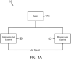
- Figure 1A depicts an example control flow and coupling diagram 10, created from the software architecture and design of a sample program under test.
- the call from a main subprogram 20 to a calculate air speed subprogram 30 should be first in the sequence; the call from the main subprogram 20 to a display air speed subprogram 40, should be second in the sequence; and there are no other subprograms called between this sequence.
- the air speed data read/used by the display air speed subprogram 40 is the same air speed data that was computed and set in the calculate air speed subprogram 30.
- the air speed is set in the calculate air speed subprogram 30 first before the air speed data is used in the display air speed subprogram 40. No other function other than the calculate air speed subprogram 30 should alter the value of the air speed data before it is read and used by the display air speed subprogram 40.
- test engineer In using manual analysis, the test engineer has to understand the software architecture, requirements, and design the test to ensure that data coupling and control coupling objectives are met. Understanding the entire software architecture is a very tedious task, especially when the software architecture diagrams are not present. Even if the software architecture diagrams are present in the form of UML diagrams, the test engineer has to put in more manual effort to understand interactions between components/modules. The test engineer must manually derive the DC-CC information, and needs to compare it with the expected DC-CC data defined in the software architecture and design to validate the correctness.
- the present approach provides a non-intrusive (instrument-less) method to generate and verify data coupling and control coupling from requirements-based test execution.
- This approach generally includes: extracting expected data and control coupling data from the software architecture and design automatically; deriving the actual control coupling information from the execution trace data obtained from requirements-based test execution; deriving the actual data coupling information from the data trace information, i.e., memory read and write operations; and comparing the actual data and control coupling information with the expected data and control coupling information automatically.
- the present method extracts actual data coupling and control coupling information, without instrumenting the source code while executing requirement-based tests.
- the present approach also provides a fully automated system, which provides an end-to-end solution of deriving the expected and actual control couplings, and comparing and providing the overall control coupling coverage status and gaps.
- a processor emulator is modified and a software component/block called a "trace control module" is added in the emulator.
- the trace control module collects and transmit the following additional data required to know information about the data and control couplings exercised: a) information about target memory read or write operation type; b) memory target address of all read and write operations and its sequence number; c) a unique incremental sequence number created and maintained for each executed instruction; d) execution trace of the program, i.e., address of all the executed instructions. Items a, b and c above are extra data in addition to the execution trace of the program.
- the present approach also provides a method of constructing the source code level data and control coupling information using the customized DC-CC trace data received from the target system (production operating environment) and disassembly file and map file.
- the address of all the read and write operations from the customized DC-CC execution trace data is extracted, then each of these addresses is checked in the map file to identify its corresponding global variable.
- Instruction type information from the customized DC-CC execution trace data is used to identify if the given operation is either read or write.
- the address of the read/write instruction from the customized DC-CC execution trace data is checked in the function address range information from the disassembly file to identify the actual function name where the given read or write operation has happened.
- a data coupling table is built using the information generated from the above steps for all the global variables, such as shown in Table 1.
- the expected control couplings are derived from analyzing the software architecture and design.
- the present approach has zero overhead on hardware resources usage, such as memory and central processing unit (CPU) throughput, and reduces the overall cycle time required for data and control coupling analysis by about 75%.
- hardware resources usage such as memory and central processing unit (CPU) throughput
- Figure 1B is flow diagram of an exemplary method 100 for measuring and verifying data and control coupling, according to one implementation.
- the method 100 comprises obtaining software architecture and design information for software under test (block 110), such as avionics software that needs to be certified.
- the method 100 further includes extracting expected control coupling information based on an order in which software component calls are in the software architecture (block 112), and extracting expected data coupling information from one software component to another software component in a sequence diagram (block 114).
- the method 100 then updates the expected control coupling information and the expected data coupling information in an expected control coupling and data coupling sequencing table (block 116).
- the method 100 also comprises deriving actual control coupling information from execution trace data obtained from a requirements-based test execution (bock 118), and deriving actual data coupling information from data trace information (block 120).
- the method 100 then updates the actual control coupling information and the actual data coupling information in an actual control coupling and data coupling sequencing table (block 122).
- method 100 compares the expected control coupling information with the actual control coupling information, and compares the expected data coupling information with the actual data coupling information, to verify that software components in the software under test are interacting with each other as expected (block 124).
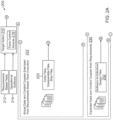
- FIGS 2A and 2B depict a software test system 200 for measuring and verifying data and control coupling, according to one embodiment.
- the test system 200 includes a target processing system 210, which can be either processor hardware or a processor emulator.
- the test system 200 is configured to receive requirement based tests 212 and as-is operational software 214.
- the target processing system 210 includes a trace control module 216, which is operative to create and transmit customized information required for data and control couplings.
- trace control module 216 is operative to create and transmit read/write target memory addresses, an address of each executed instruction, target memory operation type, and sequence number for each instruction, in real time continuously, to produce customized trace data from the requirement based tests execution (block 218).
- a data and control coupling analysis and generation system 220 is operative to produce actual data and control couples exercised from the requirements based tests execution (block 222), based on the customized trace data (from block 218) and code files, disassemble files, and map files (block 223).
- data and control coupling analysis and generation system 220 parses and analyzes customized trace data generated from the requirements based tests execution; and extracts inputs required for creating the data and control coupling information, including a list of memory addresses of all read operations (for all global variables), a list of memory addresses of all write operations (for all global variables), type of memory operations, instruction address of all memory read operations, instruction address of all memory write operations, sequence number of every executed instruction, and address of all executed instructions (block 224).
- the data and control coupling analysis and generation system 220 also parses and analyzes source code files, map files, and disassembly files; and extracts inputs required for creating the data and control coupling information, including a list of software components with start address and end address mapping, and addresses of global variables that are part of the data coupling (block 226).
- the data and control coupling analysis and generation system 220 then builds a list of actual data coupling and control couplings exercised from the requirements based tests execution using customized DC-CC supporting data extracted from the customized trace data and source code, disassembly files, and map files (block 228). This includes, for every address of each memory operation: identify the memory operation type, i.e., whether it is read or write operation; identify the global variable associated with a given memory operation; identify the software component where the given memory operation is performed; and identify the sequence number.
- the data and control coupling analysis and generation system 220 is also operative to produce expected data and control couples from requirements (block 230), based on software architecture and design files (block 232), and the information from block 226.
- the data and control coupling analysis and generation system 220 then parses and analyzes architecture and design files, and extracts inputs required for creating the expected data and control coupling information (block 234).
- the information from the software design is correlated with information extracted from the disassembly files and map files, to build a table of expected data and control couples.
- the test system 200 compares the actual and expected data and control couples, and generates an overall data and control couples coverage report, along with pass/fail status and any coverage holes (block 240), and outputs the data and control couples coverage report (block 242), for further use in the software verification process.
- Figure 3 is a functional block diagram of a control coupling analysis system 300 for measuring and verifying control coupling, according to one implementation, which can be employed by test system 200.
- the control coupling analysis system 300 is in operative communication with target processing system 210, which is configured to receive requirements based tests 212 and operational software 214 as described above ( Fig. 2 ).
- the target processing system 210 includes trace control module 216, which is operative to create and transmit the unique incremental sequence number for each executed instruction of a program, along with the address of each executed instruction (execution trace) of the program, in real time continuously, to produce customized trace files 304.
- the control coupling analysis system 300 is configured to receive information from trace files 304, along with source code files and disassemble files 306, and software architecture and design files 308.
- the control coupling analysis system 300 is operative to: analyze the software architecture and design to build an expected control couples table, including software component calls and calling sequence numbers (block 310); analyze source code files and disassemble files to build a table containing a list of software components, with start address and end address mapping (block 312); analyze the trace data generated from the requirements based tests execution, and build an actual control couples table using the software components to address mapping information (block 314); compare the actual control couples with the expected control couples, and generate an overall control couple coverage report along with pass/fail status and any coverage holes (block 316).
- the control coupling analysis system 300 then outputs the control coupling coverage data (block 320), for further use in the overall software verification process.
- control coupling analysis system 300 Further details of the operation of control coupling analysis system 300 are described as follows.
- the as-is operational software 214 is loaded into target processing system 210.
- the "as-is" meaning of operational software 214 refers to original software without instrumenting the code for DC-CC coverage tracking.
- the target processing system 210 is powered up, and the requirements based tests 212 are executed on target processing system 210.
- the trace control module 216 maintains a sequence counter, which is an incremental counter that is incremented every time an instruction is executed. The address of each executed instruction and a sequence number are collected in trace files 304 for transmission to control coupling analysis system 300, which is offline.
- the control coupling analysis system 300 reads the disassembly file of the program under test and builds a functions list lookup table containing the function name and start address of each of the functions.
- the disassembly file for the program contains the start and end address of all the functions.
- the control coupling analysis system 300 also reads the software architecture for the control flow diagram and detail design for algorithmic steps, to analyze and identify the list of control couples from the requirement. This data forms the expected control couples to be used for the control coupling coverage analysis.
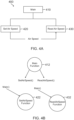
- Figure 4A is an example of a control flow and coupling diagram 400, created from the software architecture and design of a sample program under test. As shown in the example of Figure 4A , there are three components, including a main subprogram 410, which calls two subprograms, including a set air speed subprogram 420 and a read air speed subprogram 430. The set air speed is passed from subprogram 420 to subprogram 430 using an air speed global variable 440. In this example, there exists control coupling between main subprogram 410 and subprogram 420, and control coupling between main subprogram 410 and subprogram 430.
- a main subprogram 410 which calls two subprograms, including a set air speed subprogram 420 and a read air speed subprogram 430.
- the set air speed is passed from subprogram 420 to subprogram 430 using an air speed global variable 440.
- control coupling between main subprogram 410 and subprogram 420 there exists control coupling between main subpro
- Figure 4B illustrates the control couples based on control flow and coupling diagram 300.
- the following control couples are identified and a control coupling sequence table is built from requirements: control coupling between a "Main" function 412 and a "SetAirSpeed” function 422, which is the subprogram call from main subprogram 410 to set air speed subprogram 420; and the control coupling between "Main” function 412 and a "ReadAirSpeed” function 432, which is the subprogram call from main subprogram 410 to read air speed subprogram 430.
- the control coupling sequence table generated from the design requirement is given below in Table 2.
- control coupling analysis system 300 analyzes the trace data received from target processing system 210 via trace control module 216, and identifies the actual control couples exercised from requirements based test execution.
- the control coupling analysis system 300 compares the expected control couplings derived from requirements with the actual control couplings extracted from trace data, and reports the correctness status.
- An example report giving the sequence numbers, control couplings, and control coupling status is given below in Table 4.
- Table 4 Sequence Control Couplings Control Coupling Status 1 main PASS 2 main -> SetAirSpeed PASS 3 main -> ReadAirSpeed PASS 4 main -> SetAirSpeed PASS 5 main -> ReadAirSpeed PASS 6 main -> SetAirSpeed PASS 7 main -> ReadAirSpeed PASS
- FIG. 5 is a functional block diagram of a data coupling analysis system 500 for measuring and verifying datal coupling, according to one implementation, which can be employed by test system 200.
- the data coupling analysis system 500 is in operative communication with target processing system 210, which is configured to receive requirements based tests 212 and operational software 214 as described above ( Fig. 2 ).
- the target processing system 210 includes trace control module 216, which is operative to record and transmit the following data in real time: target memory read/write operation type and its sequence number; target memory address of all read/write operations; execution trace of the program, i.e., address of the executed instruction; and sequence number for each instruction. This data is used to produce customized trace files 504.
- the data coupling analysis system 500 which is offline, is configured to receive information from trace files 504, along with source code files and disassemble files 506, and software architecture and design files 508.
- the data coupling analysis system 500 is operative to: analyze the software architecture and design to build an expected data couples table, including write and set operations of global variables (parameters), their function name, and sequence number (block 510); analyze source code files and disassembly files to build a table containing a list of software components, with start address and end address mapping, and addresses of global variables that are part of data coupling (block 512); update trace control module to transmit addresses of all executed instructions, target memory read/write operations type, and memory target addresses of all read/write operations (block 514); analyze trace data generated from the requirements based tests execution to build an actual data couples table using software components to address mapping information (block 516); and compare the actual verses expected data couples, and generate an overall data couple coverage report along with pass/fail status and any coverage holes (block 518).
- the data coupling analysis system 500 then
- the operational software 214 is loaded into target processing system 210.
- the target processing system 210 is powered up, and the requirements based tests 212 are executed on target processing system 210.
- the trace control module 216 collects and transmits the following data in real time required for determining the data coupling information: target memory read/write operation type; memory target address of all read/write operations and sequence number; and address of all the executed instructions.
- the data coupling analysis system 500 reads the disassembly file of the program under test and builds a functions list lookup table containing the start address of each of the functions.
- the disassembly file for the program contains the start and end address of all the functions.
- the global variable addresses are found in the map file, and a lookup of the read/write instruction target memory address inside the trace file is performed. A determination is then made of the operations that are trying to read/write the addresses and corresponding functions, the detailed operation steps of the global variable (AirSpeed) are generated.
- the data coupling analysis system 500 compares the expected data couplings derived from requirements with the actual data couplings, and reports the correctness status.
- An example report giving the sequence numbers, data couplings, and data coupling status is given below in Table 5.
- Figure 6 is a flow diagram of a method 600 for expected CC-DC extraction from software architecture, according to an example implementation.
- method 600 fetches the software architecture (diagrams) for the software under test (block 610).
- the method 600 then extracts the expected control flow based on function calls in the order in which functions are called in the software architecture (block 612).
- the method 600 also extracts the expected data flow from one function to another function in a sequence diagram, i.e., extracts functions which are setting a variable and functions using the same variable (block 614).
- method 600 updates the expected control and data flow in a control coupling and data coupling sequencing table (expected) (block 616).
- Figure 7 is a flow diagram of a method 700 for an execution portion to obtain actual CC-DC data, according to an example implementation.
- method 700 compiles source code at 710, which is executable at 712 for process execution (in real hardware or emulator) (block 714). This produces CPU NIP/opcode/memory operation addresses at 716, and the execution ends.
- the compiled source code from 712 is also sent to a map file 720, which communicates with a CC-DC receiver 730.
- the CC-DC receiver 730 is configured to retrieve a global variable address (e.g., 060108a8 for AirSpeed, and 060108ac for VerticalSpeed) (block 732).
- a global variable address e.g., 060108a8 for AirSpeed, and 060108ac for VerticalSpeed
- the CC-DC receiver 730 is also configured to retrieve a function entry address (e.g., 06000470 for SetAirSpeed, 060004b8 for ReadAirSpeed, 06000500 for Set Vertical Speed, and 06000548 for ReadVerticalSpeed) (block 734).
- a function entry address e.g., 06000470 for SetAirSpeed, 060004b8 for ReadAirSpeed, 06000500 for Set Vertical Speed, and 06000548 for ReadVerticalSpeed
- the global variable addresses (from block 732) and function entry addresses (from block 734) are sent to a socket receiver 736, which also receives the CPU NIP/opcode/memory operation addresses (from block 716).
- Output data from socket server 736 is used in a process to determine if a function is invoked (block 740). If yes, an actual control coupling sequence table is updated (block 742). If a function is not invoked (or after the actual control coupling update), a determination is made whether there is a global variable operation (block 744). If yes, an actual data coupling sequence table is updated (block 746). If there is not a global variable operation (or after the actual datal coupling update), a determination is made whether the end of the program is reached (block 748).
- the process returns to socket receiver 736 and the above steps are repeated starting at block 740. If the end of program is reached, the process compares the expected and actual control and data couplings, and marks pass/fail in a result field (block 750). The process then comes to an end.
- FIG. 8 An example of the execution portion to obtain actual CC-DC data is shown in Figure 8 .
- the control coupling requirement included: 1) SetAirSpeed(int) should be invoked then ReadAirSpeed() can be invoked; and 2) SetVerticalSpeed(int) should be invoked then ReadVerticalSpeed can be invoked.
- the data coupling requirement included: 1) Global variable AirSpeed should set by SetAirSpeed() first then ReadAirSpeed() can read the variable; and 2) Global variable VerticalSpeed should set by SetVerticalSpeed () first then ReadVerticalSpeed () can read the variable.
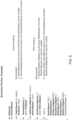
- Figure 9 shows a post analysis of the execution portion example of Figure 8 .
- the SetAirSpeed() is invoked at sequence no. 171, and the ReadAirSpeed() is invoked at sequence no. 189; the SetVerticalSpeed() is invoked at sequence no. 208, and the ReadVerticalSpeed() is invoked at sequence no. 226.
- the AirSpeed is set by SetAirSpeed() at sequence no. 181, and the AirSpeed is read by ReadAirSpeed() at sequence no. 199; the VerticalSpeed is set by SetVerticalSpeed() at sequence no. 218, and the VerticalSpeed is read by ReadVerticalSpeed() at sequence no. 236.
- expected data and control coupling information is obtained from a software architecture sequence diagram.
- a sequence diagram provides the control coupling between software modules in the order of sequence, and provides the data coupling between software components in the same sequence.
- the software architecture information is saved in an xml file format and is called (.sbs) file.
- a solution to obtain expected data and control coupling information is to parse the identity of data coupling (variables) and control coupling (function calls), the sequence in which this coupling happens, information about which component is calling which function, which component is setting data in the variable, and in which sequence the data is being used by a component from the software architecture files (.sbs) files.
- the Component Object_0 is calling message_0 function from Object_1 as a sequence 1, then object_1 component is calling message_1 as a sequence 2.
- object_1 component is calling message_1 as a sequence 2.
- data coupling as a sequence 3, Data1 is being used by Object_2 and Data 2 is set by Object_2 and used by Object_1 as a sequence 4.
- the solution parses expected information as mentioned above and generates expected data in a suitable format. This solution can parse entire information for a given project.
- Tables 6 and 7 below show the expected data and control coupling between different software components, extracted from a software architecture diagram.
- the sequence column indicates the order of sequence in which two software components (sender and receiver) are coupled from the control coupling, and also provides the order in which data is set and used by the two software components.
- high-level requirements are tested using either hardware and software integration (HSI) or software integration (SI) test methods.
- HAI hardware and software integration
- SI software integration
- the source code for an 777x ASC target is chosen and high-level requirements-based tests (HSI testing) corresponding to the software architecture and components are executed on the target. While executing the test, execution trace data is captured through a trace port and stored in the host machine along with data and control flow information.
- HAI testing high-level requirements-based tests
- the data and control flow information is captured in the following format for the sample program executed on the 777x ASC target.
- the function calls message_0 and message_1 with entry and exit is captured along with a timestamp. This provides the sequence in which the functions are executed as follow:
- MAP file sample Data: .sbss 0x00022c48 0x6 Object_1.o 0x00022c48 Data1 0x00022c4a Data3 0x00022c4c Data2
- Function .text 0x000108c4 0x5c Object_1.o 0x000108c4 message _ 0 .text 0x00010920 0x54 Object_0.o 0x00010920 main .text 0x00010974 0x3c Object_2.o 0x00010974 message_1.
- the execution trace is obtained while executing the SI test on simulator hosted on a desktop machine.
- the following sample depicts the flow in which functions are executed and data is used and stored: Message_0 (with address) is called in the beginning and data (Data1) is stored using sth instruction and read using "lhz" after storing the data.
- Data1 is identified by reading the address offset given prior to the key word "r9" and mapped with the address obtained from the MAP file with respect to base address.
- the present method automates the entire process mentioned above and generate actual data and control coupling as mentioned for the target level data and control coupling.
- the present method compares the actual with expected data and control coupling, and declares PASS or FAIL based on the sequence of control and data flow, source of the data, user of the data, function provider and user.
- Table 8 is a sample output of the comparison solution.
- Table 8 Sequence Operation Source User Type Sequence Validation 1 message_0 Object0 Object1 Control Flow True 2 message_1 Object1 Object2 Control Flow True 3 Data1 Object1 DATAFLOW True 3 Data1 Object2 DATAFLOW True 4 Data2 Object2 DATAFLOW True 4 Data2 Object1 DATAFLOW True 5 Data3 Object1 DATAFLOW True 5 Data3 Object0 DATAFLOW True PASS
- the processing units and/or other computational devices used in the method and system described herein may be implemented using software, firmware, hardware, or appropriate combinations thereof.
- the processing unit and/or other computational devices may be supplemented by, or incorporated in, specially designed application-specific integrated circuits (ASICs) or field programmable gate arrays (FPGAs).
- ASICs application-specific integrated circuits
- FPGAs field programmable gate arrays
- the processing unit and/or other computational devices may communicate through an additional transceiver with other computing devices outside of the system, such as those associated with a management system or computing devices associated with other subsystems controlled by the management system.
- the processing unit and/or other computational devices can also include or function with software programs, firmware, or other computer readable instructions for carrying out various process tasks, calculations, and control functions used in the methods and systems described herein.
- program modules include routines, programs, objects, data components, data structures, algorithms, and the like, which perform particular tasks or implement particular abstract data types.
- Instructions for carrying out the various process tasks, calculations, and generation of other data used in the operation of the methods described herein can be implemented in software, firmware, or other computer readable instructions. These instructions are typically stored on appropriate computer program products that include computer readable media used for storage of computer readable instructions or data structures. Such a computer readable medium may be available media that can be accessed by a general purpose or special purpose computer or processor, or any programmable logic device.
- Suitable computer readable storage media may include, for example, nonvolatile memory devices including semi-conductor memory devices such as Random Access Memory (RAM), Read Only Memory (ROM), Electrically Erasable Programmable ROM (EEPROM), or flash memory devices; magnetic disks such as internal hard disks or removable disks; optical storage devices such as compact discs (CDs), digital versatile discs (DVDs), Blu-ray discs; or any other media that can be used to carry or store desired program code in the form of computer executable instructions or data structures.
- RAM Random Access Memory
- ROM Read Only Memory
- EEPROM Electrically Erasable Programmable ROM
- flash memory devices such as electrically Erasable Programmable ROM (EEPROM), or flash memory devices
- magnetic disks such as internal hard disks or removable disks
- optical storage devices such as compact discs (CDs), digital versatile discs (DVDs), Blu-ray discs
- CDs compact discs
- DVDs digital versatile discs
- Example 1 includes a method comprising: obtaining software architecture and design information for software under test; extracting expected control coupling information based on an order in which software component calls are in the software architecture; extracting expected data coupling information from one software component to another software component in a sequence diagram; updating the expected control coupling information and the expected data coupling information in an expected control coupling and data coupling sequencing table; deriving actual control coupling information from execution trace data obtained from a requirements based test execution; deriving actual data coupling information from data trace information; updating the actual control coupling information and the actual data coupling information in an actual control coupling and data coupling sequencing table; and comparing the expected control coupling information with the actual control coupling information, and comparing the expected data coupling information with the actual data coupling information, to verify whether software components in the software under test are interacting with each other as expected.
- Example 2 includes the method of Example 1, wherein the execution trace data obtained from the requirements based test execution is provided by a target processing system that hosts requirements based tests and the software under test, the target processing system including a trace control module that generates the execution trace data.
- Example 3 includes the method of Example 2, wherein the expected control coupling information is extracted, and the actual control coupling information is derived, using a control coupling analysis module that is in operative communication with the target processing system.
- Example 4 includes the method of Example 3, wherein the control coupling analysis module performs a process comprising: analyzing software architecture and design files, for the software under test, to build a table of expected control couples, including software component calls and corresponding calling sequence numbers; analyzing source code and disassemble files, for the software under test, to build a table containing a list of software components with corresponding start address and end address mapping information; and analyzing the execution trace data from the requirements based tests execution, to build an actual control couples table, using the software components with corresponding address mapping information.
- Example 5 includes the method of Example 4, wherein comparing the expected control coupling information with the actual control coupling information is performed by the control coupling analysis module, which generates an overall control couple coverage report, and outputs the control couple coverage report for use in verifying that the software components in the software under test are interacting with each other as expected.
- Example 6 includes the method of any of Examples 2-5, wherein the expected data coupling information is extracted, and the actual data coupling information is derived, using a data coupling analysis module that is in operative communication with the target processing system.
- Example 7 includes the method of Example 6, wherein the data coupling analysis module performs a process comprising: analyzing software architecture and design files, for the software under test, to build a table of expected data couples, including read and set operations of global variables, and sequence number; analyzing source code files and disassembly files to build a table containing a list of software components, with corresponding start address and end address mapping information, and addresses of global variables that are part of data coupling; updating the trace control module to transmit addresses of all executed instructions, a target memory read/write operations type, and memory target addresses of all read/write operations; and analyzing the execution trace data from the requirements based tests execution, to build an actual data couples table using the software components and corresponding address mapping information.
- Example 8 includes the method of Example 7, wherein comparing the expected data coupling information with the actual data coupling information is performed by the data coupling analysis module, which generates an overall data couple coverage report, and outputs the data couple coverage report for use in verifying that the software components in the software under test are interacting with each other as expected.
- Example 9 includes the method of any of Examples 1-8, wherein the software under test comprises avionics software.
- Example 10 includes the method of Example 9, wherein the avionics software is subject to certification under DO-178C guidelines.
- Example 11 includes a system for measuring and verifying data and control couplings of software under test, the system comprising: a target processing system configured to receive requirements based tests and the software under test, the target processing system including a trace control module operative to generate customized trace data from execution of the requirements based tests; and a data and control coupling analysis system in operative communication with the target processing system, wherein the data and control coupling analysis system is operative to produce actual data and control couples exercised from the execution of the requirements based tests, by a process that comprises: receive the customized trace data from execution of the requirements based tests from the target processing system; parse and analyze the customized trace data to extract a first set of inputs for creating actual data and control coupling information; parse and analyze source code files, map files, and disassembly files for the software under test, to extract a second set of inputs for creating the actual data and control coupling information; build a list of the actual data and control couples using customized supporting data extracted from the customized trace data, the source code files, the map files,
- Example 12 includes the system of Example 11, wherein the first set of inputs for creating the actual data and control coupling information comprises: a list of memory addresses of all read operations for all global variables; a list of memory addresses of all write operations for all the global variables; identification of type for all memory operations; an instruction address for all memory read operations; an instruction address for all memory write operations; a sequence number of each executed instruction; and an address of each executed instruction.
- Example 13 includes the system of any of Examples 11-12, wherein the second set of inputs for creating the actual data and control coupling information comprises: a list of software components with corresponding start address and end address mapping; and addresses of global variables that are part of data coupling.
- Example 14 includes the system of any of Examples 11-13, wherein the list of actual data and control couplings comprises, for every address of each memory operation: identification of memory operation type as read operation or write operation; identification of the global variable associated with a given memory operation; identification of the software component where the given memory operation is performed; and identification of the sequence number of the given memory operation.
- Example 15 includes the system of any of Examples 11-14, wherein the target processing system includes processor hardware or a processor emulator.
- Example 16 includes the system of any of Examples 11-15, wherein the trace control module is operative to create and transmit read/write target memory addresses, an address of each executed instruction, target memory operation type, and sequence number for each instruction, in real time continuously, to produce the customized trace data from the execution of the requirements based tests.
- Example 17 includes the system of any of Examples 11-16, wherein the overall data and control couples coverage report includes a pass/fail status for each software component, and any coverage holes.
- Example 18 includes the system of any of Examples 11-17, wherein the software under test comprises avionics software.
- Example 19 includes the system of Example 18, wherein the avionics software is subject to certification under DO-178C guidelines.
- Example 20 includes a program product comprising: a processor readable medium having instructions stored thereon, executable by at least one processor, to perform a method for measuring and verifying data and control couplings of software under test, the method comprising: obtaining software architecture and design information for the software under test; extracting expected control coupling information based on an order in which software component calls are in the software architecture; extracting expected data coupling information from one software component to another software component in a sequence diagram; updating the expected control coupling information and the expected data coupling information in an expected control coupling and data coupling sequencing table; deriving actual control coupling information from execution trace data obtained from a requirements based test execution; deriving actual data coupling information from data trace information; updating the actual control coupling information and the actual data coupling information in an actual control coupling and data coupling sequencing table; and comparing the expected control coupling information with the actual control coupling information, and comparing the expected data coupling information with the actual data coupling information, to verify whether software components in the software under test are interacting with each other as expected
Landscapes
- Engineering & Computer Science (AREA)
- Theoretical Computer Science (AREA)
- Computer Hardware Design (AREA)
- Quality & Reliability (AREA)
- Physics & Mathematics (AREA)
- General Engineering & Computer Science (AREA)
- General Physics & Mathematics (AREA)
- Software Systems (AREA)
- Debugging And Monitoring (AREA)
Applications Claiming Priority (2)
| Application Number | Priority Date | Filing Date | Title |
|---|---|---|---|
| IN202311003549 | 2023-01-18 | ||
| US18/180,751 US12399802B2 (en) | 2023-01-18 | 2023-03-08 | System and method to measure and verify data and control coupling between software components without code instrumentation |
Publications (1)
| Publication Number | Publication Date |
|---|---|
| EP4404067A1 true EP4404067A1 (de) | 2024-07-24 |
Family
ID=89474104
Family Applications (1)
| Application Number | Title | Priority Date | Filing Date |
|---|---|---|---|
| EP24150536.1A Pending EP4404067A1 (de) | 2023-01-18 | 2024-01-05 | System und verfahren zur messung und überprüfung von daten und steuerung der kopplung zwischen softwarekomponenten ohne codeinstrumentierung |
Country Status (1)
| Country | Link |
|---|---|
| EP (1) | EP4404067A1 (de) |
Citations (2)
| Publication number | Priority date | Publication date | Assignee | Title |
|---|---|---|---|---|
| US20100107180A1 (en) * | 2007-06-06 | 2010-04-29 | Andreas Ulrich | Method for providing reference data for a diagnosis of a system dependent on an event trace |
| WO2022256103A1 (en) * | 2021-06-04 | 2022-12-08 | Ldra Technology, Inc. | Verification of control coupling and data coupling analysis in software code |
-
2024
- 2024-01-05 EP EP24150536.1A patent/EP4404067A1/de active Pending
Patent Citations (2)
| Publication number | Priority date | Publication date | Assignee | Title |
|---|---|---|---|---|
| US20100107180A1 (en) * | 2007-06-06 | 2010-04-29 | Andreas Ulrich | Method for providing reference data for a diagnosis of a system dependent on an event trace |
| WO2022256103A1 (en) * | 2021-06-04 | 2022-12-08 | Ldra Technology, Inc. | Verification of control coupling and data coupling analysis in software code |
Non-Patent Citations (2)
| Title |
|---|
| ANONYMOUS: "Data Coupling and Control Coupling Verification VectorCAST | Vector", 24 May 2022 (2022-05-24), pages 1 - 5, XP093171640, Retrieved from the Internet <URL:http://web.archive.org/web/20220524082255/https://www.vector.com/us/en/products/products-a-z/software/vectorcast/vectorcast-coupling/> * |
| VECTOR: "Complete Verification and Validation for DO-178C Whitepaper - V1.0 2019-10", WHITEPAPERS OF VECTOR, 1 October 2019 (2019-10-01), pages 1 - 20, XP055904811, Retrieved from the Internet <URL:https://cdn.vector.com/cms/content/know-how/aerospace/Documents/Complete_Verification_and_Validation_for_DO-178C.pdf> [retrieved on 20220323] * |
Similar Documents
| Publication | Publication Date | Title |
|---|---|---|
| US9317400B2 (en) | Code coverage rate determination method and system | |
| US11386154B2 (en) | Method for generating a graph model for monitoring machinery health | |
| CN112560372B (zh) | 一种芯片原型验证方法、装置、设备及介质 | |
| US20130263092A1 (en) | Method of converting source code and source code conversion program | |
| CN113742215B (zh) | 一种自动配置和调用测试工具进行测试分析的方法及系统 | |
| US20050028146A1 (en) | Systems and methods for software and firmware testing using checkpoint signatures | |
| US20200143292A1 (en) | Signature enhancement for deviation measurement-based classification of a detected anomaly in an industrial asset | |
| US10657028B2 (en) | Method for replicating production behaviours in a development environment | |
| US20180203844A1 (en) | Detection of meaningful changes in content | |
| CN111045927A (zh) | 性能测试评估方法、装置、计算机设备及可读存储介质 | |
| CN107045477B (zh) | 一种可进行多维度检测的质量评估平台 | |
| CN113220594A (zh) | 自动化测试方法、装置、设备及存储介质 | |
| KR102269286B1 (ko) | 어노테이션 자동 진단 시스템 | |
| CN119179642A (zh) | 一种代码测试方法、装置及电子设备 | |
| US7882493B2 (en) | Software test management program software test management apparatus and software test management method | |
| CN112925524A (zh) | 一种检测驱动程序中不安全直接存储器访问的方法及装置 | |
| Kanashiro et al. | Predicting software flaws with low complexity models based on static analysis data | |
| CN119357060A (zh) | 单元测试用例生成方法、装置、设备及介质 | |
| KR20190136352A (ko) | 소프트웨어 검사 장치 및 방법 | |
| CN116627804A (zh) | 基于人工智能的测试方法、系统、电子设备及存储介质 | |
| US12399802B2 (en) | System and method to measure and verify data and control coupling between software components without code instrumentation | |
| US7668680B2 (en) | Operational qualification by independent reanalysis of data reduction patch | |
| Alzahrani | Measuring class cohesion based on client similarities between method pairs: An improved approach that supports refactoring | |
| US20170242775A1 (en) | Method for verifying traceability of first instructions in a procedural programming language generated from second instructions in a modelling language | |
| CN118363841A (zh) | 用于在没有代码插桩的情况下测量并验证软件组件之间的数据和控制耦合的系统和方法 |
Legal Events
| Date | Code | Title | Description |
|---|---|---|---|
| PUAI | Public reference made under article 153(3) epc to a published international application that has entered the european phase |
Free format text: ORIGINAL CODE: 0009012 |
|
| STAA | Information on the status of an ep patent application or granted ep patent |
Free format text: STATUS: THE APPLICATION HAS BEEN PUBLISHED |
|
| AK | Designated contracting states |
Kind code of ref document: A1 Designated state(s): AL AT BE BG CH CY CZ DE DK EE ES FI FR GB GR HR HU IE IS IT LI LT LU LV MC ME MK MT NL NO PL PT RO RS SE SI SK SM TR |
|
| STAA | Information on the status of an ep patent application or granted ep patent |
Free format text: STATUS: REQUEST FOR EXAMINATION WAS MADE |
|
| 17P | Request for examination filed |
Effective date: 20240930 |
|
| RBV | Designated contracting states (corrected) |
Designated state(s): AL AT BE BG CH CY CZ DE DK EE ES FI FR GB GR HR HU IE IS IT LI LT LU LV MC ME MK MT NL NO PL PT RO RS SE SI SK SM TR |