EP4404034A1 - Multifunktionssteuerung und anzeige - Google Patents
Multifunktionssteuerung und anzeige Download PDFInfo
- Publication number
- EP4404034A1 EP4404034A1 EP23220352.1A EP23220352A EP4404034A1 EP 4404034 A1 EP4404034 A1 EP 4404034A1 EP 23220352 A EP23220352 A EP 23220352A EP 4404034 A1 EP4404034 A1 EP 4404034A1
- Authority
- EP
- European Patent Office
- Prior art keywords
- control knob
- aircraft
- flight
- display
- touch screen
- Prior art date
- Legal status (The legal status is an assumption and is not a legal conclusion. Google has not performed a legal analysis and makes no representation as to the accuracy of the status listed.)
- Withdrawn
Links
Images


Classifications
-
- G—PHYSICS
- G06—COMPUTING OR CALCULATING; COUNTING
- G06F—ELECTRIC DIGITAL DATA PROCESSING
- G06F3/00—Input arrangements for transferring data to be processed into a form capable of being handled by the computer; Output arrangements for transferring data from processing unit to output unit, e.g. interface arrangements
- G06F3/01—Input arrangements or combined input and output arrangements for interaction between user and computer
- G06F3/03—Arrangements for converting the position or the displacement of a member into a coded form
- G06F3/033—Pointing devices displaced or positioned by the user, e.g. mice, trackballs, pens or joysticks; Accessories therefor
- G06F3/0362—Pointing devices displaced or positioned by the user, e.g. mice, trackballs, pens or joysticks; Accessories therefor with detection of 1D translations or rotations of an operating part of the device, e.g. scroll wheels, sliders, knobs, rollers or belts
-
- B—PERFORMING OPERATIONS; TRANSPORTING
- B60—VEHICLES IN GENERAL
- B60K—ARRANGEMENT OR MOUNTING OF PROPULSION UNITS OR OF TRANSMISSIONS IN VEHICLES; ARRANGEMENT OR MOUNTING OF PLURAL DIVERSE PRIME-MOVERS IN VEHICLES; AUXILIARY DRIVES FOR VEHICLES; INSTRUMENTATION OR DASHBOARDS FOR VEHICLES; ARRANGEMENTS IN CONNECTION WITH COOLING, AIR INTAKE, GAS EXHAUST OR FUEL SUPPLY OF PROPULSION UNITS IN VEHICLES
- B60K35/00—Instruments specially adapted for vehicles; Arrangement of instruments in or on vehicles
- B60K35/10—Input arrangements, i.e. from user to vehicle, associated with vehicle functions or specially adapted therefor
-
- B—PERFORMING OPERATIONS; TRANSPORTING
- B60—VEHICLES IN GENERAL
- B60K—ARRANGEMENT OR MOUNTING OF PROPULSION UNITS OR OF TRANSMISSIONS IN VEHICLES; ARRANGEMENT OR MOUNTING OF PLURAL DIVERSE PRIME-MOVERS IN VEHICLES; AUXILIARY DRIVES FOR VEHICLES; INSTRUMENTATION OR DASHBOARDS FOR VEHICLES; ARRANGEMENTS IN CONNECTION WITH COOLING, AIR INTAKE, GAS EXHAUST OR FUEL SUPPLY OF PROPULSION UNITS IN VEHICLES
- B60K35/00—Instruments specially adapted for vehicles; Arrangement of instruments in or on vehicles
- B60K35/20—Output arrangements, i.e. from vehicle to user, associated with vehicle functions or specially adapted therefor
- B60K35/21—Output arrangements, i.e. from vehicle to user, associated with vehicle functions or specially adapted therefor using visual output, e.g. blinking lights or matrix displays
- B60K35/212—Output arrangements, i.e. from vehicle to user, associated with vehicle functions or specially adapted therefor using visual output, e.g. blinking lights or matrix displays displaying on manual operation elements, e.g. on a knob
-
- B—PERFORMING OPERATIONS; TRANSPORTING
- B64—AIRCRAFT; AVIATION; COSMONAUTICS
- B64C—AEROPLANES; HELICOPTERS
- B64C13/00—Control systems or transmitting systems for actuating flying-control surfaces, lift-increasing flaps, air brakes, or spoilers
- B64C13/02—Initiating means
- B64C13/04—Initiating means actuated personally
- B64C13/042—Initiating means actuated personally operated by hand
-
- B—PERFORMING OPERATIONS; TRANSPORTING
- B64—AIRCRAFT; AVIATION; COSMONAUTICS
- B64D—EQUIPMENT FOR FITTING IN OR TO AIRCRAFT; FLIGHT SUITS; PARACHUTES; ARRANGEMENT OR MOUNTING OF POWER PLANTS OR PROPULSION TRANSMISSIONS IN AIRCRAFT
- B64D43/00—Arrangements or adaptations of instruments
-
- B—PERFORMING OPERATIONS; TRANSPORTING
- B64—AIRCRAFT; AVIATION; COSMONAUTICS
- B64D—EQUIPMENT FOR FITTING IN OR TO AIRCRAFT; FLIGHT SUITS; PARACHUTES; ARRANGEMENT OR MOUNTING OF POWER PLANTS OR PROPULSION TRANSMISSIONS IN AIRCRAFT
- B64D45/00—Aircraft indicators or protectors not otherwise provided for
-
- G—PHYSICS
- G01—MEASURING; TESTING
- G01C—MEASURING DISTANCES, LEVELS OR BEARINGS; SURVEYING; NAVIGATION; GYROSCOPIC INSTRUMENTS; PHOTOGRAMMETRY OR VIDEOGRAMMETRY
- G01C23/00—Combined instruments indicating more than one navigational value, e.g. for aircraft; Combined measuring devices for measuring two or more variables of movement, e.g. distance, speed or acceleration
-
- G—PHYSICS
- G06—COMPUTING OR CALCULATING; COUNTING
- G06F—ELECTRIC DIGITAL DATA PROCESSING
- G06F3/00—Input arrangements for transferring data to be processed into a form capable of being handled by the computer; Output arrangements for transferring data from processing unit to output unit, e.g. interface arrangements
- G06F3/01—Input arrangements or combined input and output arrangements for interaction between user and computer
- G06F3/03—Arrangements for converting the position or the displacement of a member into a coded form
- G06F3/041—Digitisers, e.g. for touch screens or touch pads, characterised by the transducing means
-
- G—PHYSICS
- G06—COMPUTING OR CALCULATING; COUNTING
- G06F—ELECTRIC DIGITAL DATA PROCESSING
- G06F3/00—Input arrangements for transferring data to be processed into a form capable of being handled by the computer; Output arrangements for transferring data from processing unit to output unit, e.g. interface arrangements
- G06F3/01—Input arrangements or combined input and output arrangements for interaction between user and computer
- G06F3/048—Interaction techniques based on graphical user interfaces [GUI]
- G06F3/0484—Interaction techniques based on graphical user interfaces [GUI] for the control of specific functions or operations, e.g. selecting or manipulating an object, an image or a displayed text element, setting a parameter value or selecting a range
- G06F3/04847—Interaction techniques to control parameter settings, e.g. interaction with sliders or dials
-
- B—PERFORMING OPERATIONS; TRANSPORTING
- B60—VEHICLES IN GENERAL
- B60K—ARRANGEMENT OR MOUNTING OF PROPULSION UNITS OR OF TRANSMISSIONS IN VEHICLES; ARRANGEMENT OR MOUNTING OF PLURAL DIVERSE PRIME-MOVERS IN VEHICLES; AUXILIARY DRIVES FOR VEHICLES; INSTRUMENTATION OR DASHBOARDS FOR VEHICLES; ARRANGEMENTS IN CONNECTION WITH COOLING, AIR INTAKE, GAS EXHAUST OR FUEL SUPPLY OF PROPULSION UNITS IN VEHICLES
- B60K2360/00—Indexing scheme associated with groups B60K35/00 or B60K37/00 relating to details of instruments or dashboards
- B60K2360/126—Rotatable input devices for instruments
-
- B—PERFORMING OPERATIONS; TRANSPORTING
- B60—VEHICLES IN GENERAL
- B60K—ARRANGEMENT OR MOUNTING OF PROPULSION UNITS OR OF TRANSMISSIONS IN VEHICLES; ARRANGEMENT OR MOUNTING OF PLURAL DIVERSE PRIME-MOVERS IN VEHICLES; AUXILIARY DRIVES FOR VEHICLES; INSTRUMENTATION OR DASHBOARDS FOR VEHICLES; ARRANGEMENTS IN CONNECTION WITH COOLING, AIR INTAKE, GAS EXHAUST OR FUEL SUPPLY OF PROPULSION UNITS IN VEHICLES
- B60K2360/00—Indexing scheme associated with groups B60K35/00 or B60K37/00 relating to details of instruments or dashboards
- B60K2360/143—Touch sensitive instrument input devices
- B60K2360/1438—Touch screens
-
- B—PERFORMING OPERATIONS; TRANSPORTING
- B60—VEHICLES IN GENERAL
- B60K—ARRANGEMENT OR MOUNTING OF PROPULSION UNITS OR OF TRANSMISSIONS IN VEHICLES; ARRANGEMENT OR MOUNTING OF PLURAL DIVERSE PRIME-MOVERS IN VEHICLES; AUXILIARY DRIVES FOR VEHICLES; INSTRUMENTATION OR DASHBOARDS FOR VEHICLES; ARRANGEMENTS IN CONNECTION WITH COOLING, AIR INTAKE, GAS EXHAUST OR FUEL SUPPLY OF PROPULSION UNITS IN VEHICLES
- B60K2360/00—Indexing scheme associated with groups B60K35/00 or B60K37/00 relating to details of instruments or dashboards
- B60K2360/16—Type of output information
- B60K2360/167—Vehicle dynamics information
-
- B—PERFORMING OPERATIONS; TRANSPORTING
- B60—VEHICLES IN GENERAL
- B60Y—INDEXING SCHEME RELATING TO ASPECTS CROSS-CUTTING VEHICLE TECHNOLOGY
- B60Y2200/00—Type of vehicle
- B60Y2200/50—Aeroplanes, Helicopters
Definitions
- the present invention generally relates to aircraft control systems, and more particularly relates to a multifunctional controller and display.
- An apparatus for providing dual touch and physical control inputs for an aircraft control panel.
- the apparatus comprises: a cylindrical shaped control knob that is rotatably mounted on the aircraft control panel, where the control knob comprises, a movable surface around the exterior of control knob, where the movable surface may be manually adjusted by a user, a touch screen along the circular top of the control knob, where the touch screen may be tactilely adjusted by a user, and a display screen located on the touch screen that shows values of flight performance characteristics, where the values of the flight performance characteristics are controlled by inputs from the control knob; and a flight display panel that shows image data of the aircraft with reference to the flight performance characteristics.
- a method for providing dual touch and physical control inputs for an aircraft control panel comprises: displaying the values of the flight performance characteristics by inputs from a cylindrical shaped control knob that is rotatably mounted on the aircraft control panel, where the control knob comprises a movable surface around the exterior of control knob, where the movable surface may be manually adjusted by a user, a touch screen along the circular top of the control knob, where the touch screen may be tactilely adjusted by a user, and a display screen located on the touch screen that shows values of flight performance characteristics; selecting the flight characteristics to be adjusted, where the flight characteristics are selected with the touch screen; adjusting a flight characteristic with the movable surface; adjusting an alternative flight characteristic with the touch screen; and showing image data of the aircraft with reference to the flight performance characteristics on a flight display panel.
- module refers to any hardware, software, firmware, electronic control component, processing logic, and/or processor device, individually or in any combination, including without limitation: application specific integrated circuit (ASIC), an electronic circuit, a processor (shared, dedicated, or group) and memory that executes one or more software or firmware programs, a combinational logic circuit, and/or other suitable components that provide the described functionality.
- ASIC application specific integrated circuit
- the provided system and method may be separate from, or integrated within, a preexisting mobile platform management system, avionics system, or aircraft flight management system (FMS).
- FMS aircraft flight management system
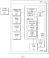
- the vehicle system 102 includes: the control module 104 that is operationally coupled to a communication system 106, an imaging system 108, a navigation system 110, a user input device 112, a display system 114, and a graphics system 116.
- the depicted vehicle system 102 is generally realized as an aircraft flight deck display system within a vehicle 100 that is an aircraft; however, the concepts presented here can be deployed in a variety of mobile platforms, such as land vehicles, spacecraft, watercraft, and the like. Accordingly, in various embodiments, the vehicle system 102 may be associated with or form part of larger aircraft management system, such as a flight management system (FMS).
- FMS flight management system
- control module 104 is coupled to the communications system 106, which is configured to support communications between external data source(s) 120 and the aircraft.
- External source(s) 120 may comprise air traffic control (ATC), or other suitable command centers and ground locations.
- Data received from the external source(s) 120 includes the instantaneous, or current, visibility report associated with a target landing location or identified runway.
- the communications system 106 may be realized using a radio communication system or another suitable data link system.
- the imaging system 108 is configured to use sensing devices to generate video or still images and provide image data therefrom.
- the imaging system 108 may comprise one or more sensing devices, such as cameras, each with an associated sensing method. Accordingly, the video or still images generated by the imaging system 108 may be referred to herein as generated images, sensor images, or sensed images, and the image data may be referred to as sensed data.
- the imaging system 108 comprises an infrared ("IR") based video camera, low-light TV camera, or a millimeter wave (MMW) video camera.
- the IR camera senses infrared radiation to create an image in a manner that is similar to an optical camera sensing visible light to create an image.
- the imaging system 108 comprises a radar based video camera system. Radar based systems emit pulses of electromagnetic radiation and listen for, or sense, associated return echoes. The radar system may generate an image or video based upon the sensed echoes.
- the imaging system 108 may comprise a sonar system. The imaging system 108 uses methods other than visible light to generate images, and the sensing devices within the imaging system 108 are much more sensitive than a human eye. Consequently, the generated images may comprise objects, such as mountains, buildings, or ground objects, that a pilot might not otherwise see due to low visibility conditions.
- the imaging system 108 may be mounted in or near the nose of the aircraft (vehicle 100) and calibrated to align an imaging region with a viewing region of a primary flight display (PFD) or a Head Up display (HUD) rendered on the display system 114.
- the imaging system 108 may be configured so that a geometric center of its field of view (FOV) is aligned with or otherwise corresponds to the geometric center of the viewing region on the display system 114.
- FOV field of view
- the imaging system 108 may be oriented or otherwise directed substantially parallel to an anticipated line-of-sight for a pilot and/or crew member in the cockpit of the aircraft to effectively capture a forward looking cockpit view in the respective displayed image.
- the displayed images on the display system 114 are three dimensional, and the imaging system 108 generates a synthetic perspective view of terrain in front of the aircraft.
- the synthetic perspective view of terrain in front of the aircraft is generated to match the direct out-the-window view of a crew member, and may be based on the current position, attitude, and pointing information received from a navigation system 110, or other aircraft and/or flight management systems.
- Navigation system 110 is configured to provide real-time navigational data and/or information regarding operation of the aircraft.
- the navigation system 110 may be realized as a global positioning system (GPS), inertial reference system (IRS), or a radio-based navigation system (e.g., VHF omni-directional radio range (VOR) or long range aid to navigation (LORAN)), and may include one or more navigational radios or other sensors suitably configured to support operation of the navigation system 110, as will be appreciated in the art.
- the navigation system 110 is capable of obtaining and/or determining the current or instantaneous position and location information of the aircraft (e.g., the current latitude and longitude) and the current altitude or above ground level for the aircraft.
- the navigation system 110 includes inertial reference sensors capable of obtaining or otherwise determining the attitude or orientation (e.g., the pitch, roll, and yaw, heading) of the aircraft relative to earth.
- the user input device 112 is coupled to the control module 104, and the user input device 112 and the control module 104 are cooperatively configured to allow a user (e.g., a pilot, co-pilot, or crew member) to interact with the display system 114 and/or other elements of the vehicle system 102 in a conventional manner.
- the user input device 112 may include any one, or combination, of various known user input device devices including, but not limited to: a touch sensitive screen; a cursor control device (CCD) (not shown), such as a mouse, a touchpad, a touchscreen, a trackball, or joystick; a keyboard; one or more buttons, switches, or knobs; a voice input system; and a gesture recognition system.
- the user input device 112 may be integrated with a display device.
- Non-limiting examples of uses for the user input device 112 include: entering values for stored variables 164, loading or updating instructions and applications 160, and loading and updating the contents of the database 156, each described in more detail below.
- the generated images from the imaging system 108 are provided to the control module 104 in the form of image data.
- the control module 104 is configured to receive the image data and convert and render the image data into display commands that command and control the renderings of the display system 114. This conversion and rendering may be performed, at least in part, by the graphics system 116.
- the graphics system 116 may be integrated within the control module 104; in other embodiments, the graphics system 116 may be integrated within the display system 114.
- the display system 114 responsive to receiving display commands from the control module 104, displays, renders, or otherwise conveys one or more graphical representations or displayed images based on the image data (i.e., sensor based images) and associated with operation of the vehicle 100, as described in greater detail below.
- images displayed on the display system 114 may also be responsive to processed user input that was received via a user input device 112.
- the display system 114 may include any device or apparatus suitable for displaying flight information or other data associated with operation of the aircraft in a format viewable by a user.
- Display methods include various types of computer generated symbols, text, and graphic information representing, for example, pitch, heading, flight path, airspeed, altitude, runway information, waypoints, targets, obstacle, terrain, and required navigation performance (RNP) data in an integrated, multi-color or monochrome form.
- the display system 114 may be part of, or include, a primary flight display (PFD) system, a panel-mounted head down display (HDD), a head up display (HUD), or a head mounted display system, such as a "near to eye display" system.
- PFD primary flight display
- HDD panel-mounted head down display
- HUD head up display
- a head mounted display system such as a "near to eye display" system.
- the display system 114 may comprise display devices that provide three dimensional or two dimensional images, and may provide synthetic vision imaging.
- display devices include cathode ray tube (CRT) displays, and flat panel displays such as LCD (liquid crystal displays) and TFT (thin film transistor) displays.
- CTR cathode ray tube
- LCD liquid crystal displays
- TFT thin film transistor
- control module 104 performs the functions of the vehicle system 102.
- the processor 150 and the memory 152 (having therein the program 162) form a novel processing engine that performs the described processing activities in accordance with the program 162, as is described in more detail below.
- the control module 104 generates display signals that command and control the display system 114.
- the control module 104 includes an interface 154, communicatively coupled to the processor 150 and memory 152 (via a bus 155), database 156, and an optional storage disk 158. In various embodiments, the control module 104 performs actions and other functions in accordance with other embodiments.
- the processor 150 may comprise any type of processor or multiple processors, single integrated circuits such as a microprocessor, or any suitable number of integrated circuit devices and/or circuit boards working in cooperation to carry out the described operations, tasks, and functions by manipulating electrical signals representing data bits at memory locations in the system memory, as well as other processing of signals.
- the memory 152, the database 156, or a disk 158 maintain data bits and may be utilized by the processor 150 as both storage and a scratch pad.
- the memory locations where data bits are maintained are physical locations that have particular electrical, magnetic, optical, or organic properties corresponding to the data bits.
- the memory 152 can be any type of suitable computer readable storage medium.
- the memory 152 may include various types of dynamic random access memory (DRAM) such as SDRAM, the various types of static RAM (SRAM), and the various types of non-volatile memory (PROM, EPROM, and flash).
- DRAM dynamic random access memory
- SRAM static RAM
- PROM non-volatile memory
- the memory 152 is located on and/or co-located on the same computer chip as the processor 150.
- the memory 152 stores the above-referenced instructions and applications 160 along with one or more configurable variables in stored variables 164.
- the database 156 and the disk 158 are computer readable storage media in the form of any suitable type of storage apparatus, including direct access storage devices such as hard disk drives, flash systems, floppy disk drives and optical disk drives.
- the database may include an airport database (comprising airport features) and a terrain database (comprising terrain features). In combination, the features from the airport database and the terrain database are referred to map features.
- Information in the database 156 may be organized and/or imported from an external source 120 during an initialization step of a process.
- the bus 155 serves to transmit programs, data, status and other information or signals between the various components of the control module 104.
- the bus 155 can be any suitable physical or logical means of connecting computer systems and components. This includes, but is not limited to, direct hard-wired connections, fiber optics, infrared and wireless bus technologies.
- the interface 154 enables communications within the control module 104, can include one or more network interfaces to communicate with other systems or components, and can be implemented using any suitable method and apparatus.
- the interface 154 enables communication from a system driver and/or another computer system.
- the interface 154 obtains data from external data source(s) 120 directly.
- the interface 154 may also include one or more network interfaces to communicate with technicians, and/or one or more storage interfaces to connect to storage apparatuses, such as the database 156.
- vehicle system 102 may differ from the embodiment depicted in FIG. 1 .
- vehicle system 102 can be integrated with an existing flight management system (FMS) or aircraft flight deck display.
- FMS flight management system
- the processor 150 loads and executes one or more programs, algorithms and rules embodied as instructions and applications 160 contained within the memory 152 and, as such, controls the general operation of the control module 104 as well as the vehicle system 102. In executing the process described herein, the processor 150 specifically loads and executes the novel program 162. Additionally, the processor 150 is configured to process received inputs (any combination of input from the communication system 106, the imaging system 108, the navigation system 110, and user input provided via user input device 112), reference the database 156 in accordance with the program 162, and generate display commands that command and control the display system 114 based thereon.
- the controller 200 is cylindrically shaped control knob and it is typically mounted on an aircraft control panel.
- the control knob includes a rotatable surface 202 around the exterior of control knob where it may be manually adjusted by a user by dialing in a clockwise and/or counter-clockwise direction.
- a touch screen 204 is located along the circular top surface of the control knob where it may be tactilely adjusted by a user.
- a display screen located on the touch screen that shows values of flight performance characteristics, which are controlled by inputs from the control knob or touch screen.
- the multifunctional controller 200 replaces several different control devices for an aircraft both touchscreen and physical.
- the controller provides physical controls and haptic feedback during turbulence and other dynamic environments when needed by aircrew.
- the controller provides a physical controller and data input device that provides the flight crew with a stable and predictable way to change flight data while in dynamic flight environment.
- FIG. 3 diagrams 300 are shown of types of inputs for a multifunctional controller and display in accordance with one embodiment.
- the inputs 302 for the rotatable surface of the control knob include rotating in a clockwise and/or counter-clockwise direction. Also, the control knob may be nudged in a vertical and/or horizontal direction similar to a joystick.
- the touch screen may receive inputs 304 from a touch or press as well as swiping in a vertical and/or horizontal direction.
- FIG. 4 various views 400 are shown of the display for a multifunctional controller and display in accordance with one embodiment. Each function for input is shown on a home screen and it may be selected for input by swiping the touchscreen for inputting information for that selected function.
- the heading (HDG) of the aircraft is adjusted by swiping the touchscreen 402. In an alternative, the heading (HDG) of the aircraft is adjusted by nudging the control knob 408. In another example, the altitude of the aircraft is set with the rotatable dial 404. In an alternative, the altitude of the aircraft is set by pressing the touch screen 406. In other embodiments, a touch pad (not shown) on the touchscreen could be used to type in the numerals for the desired value of the flight characteristic. In another example, the radio frequency of the aircraft is set by nudging the control knob 410. In still another example, the radio volume is adjusted with the rotatable dial 412. It should be understood that a wide variety of flight characteristics may be controlled and adjusted by the various types of inputs from the control knob. Additionally, these input controls may be customized to the user's preference in other embodiments.
- FIG. 5 a perspective view 500 is shown of a cockpit layout for multiple flight displays and a multifunctional controller and display in accordance with one embodiment.
- the multifunctional controller is shown in a Single Pilot Operation (SPO) Configuration.
- the multifunctional controller may also be used for Dual Pilot Operations (DPO) or larger flight decks.
- the multifunction controller 504 is located on the flight control panel along with multiple flight display panels 502 that show image data of the aircraft with reference to the flight performance characteristics as set by the controller 504.
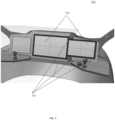
- FIG. 6 a perspective view 600 is shown of multiple flight displays 604 showing image data of the aircraft and a multifunctional controller and display 602 in accordance with another embodiment.
- FIG. 6 a perspective view 600 is shown of multiple flight displays 604 showing image data of the aircraft and a multifunctional controller and display 602 in accordance with another embodiment.
- a perspective view 700 is shown of multiple flight displays 704 and multiple multifunctional controllers and displays 702 in accordance with one embodiment.
- multiple controllers 702 could be used to control different flight characteristics.
- the controllers 702 could also be located at different locations on the flight control panel.
- FIG. 8 a flowchart 800 is shown depicting a method for providing dual touch and physical control inputs for an aircraft control panel.
- the method includes displaying and controlling the values of the flight performance characteristics by inputs from a cylindrical shaped control knob that is rotatably mounted on the aircraft control panel 802.
- the control knob includes a movable rotating surface around the exterior of control knob 804, that is manually adjusted by a user and a touch screen 806 along the circular top of the control knob that is tactilely adjusted by the user.
- the flight characteristics to be adjusted are selected by swiping the touchscreen in some embodiments 803. Once selected, the flight characteristics may be adjusted with the rotatable surface 804, with the touch screen 806 or both.
- a display screen located on the touch screen shows values of flight performance characteristics 808 that are adjusted by the user.
- a flight display panel shows image data of the aircraft with reference to the flight performance characteristics 810.
- an embodiment of a system or a component may employ various integrated circuit components, e.g., memory elements, digital signal processing elements, logic elements, look-up tables, or the like, which may carry out a variety of functions under the control of one or more microprocessors or other control devices.
- integrated circuit components e.g., memory elements, digital signal processing elements, logic elements, look-up tables, or the like, which may carry out a variety of functions under the control of one or more microprocessors or other control devices.
- various elements of the systems described herein are essentially the code segments or instructions that perform the various tasks.
- the program or code segments can be stored in a processor-readable medium or transmitted by a computer data signal embodied in a carrier wave over a transmission medium or communication path.
- the "computer-readable medium”, “processor-readable medium”, or “machine-readable medium” may include any medium that can store or transfer information. Examples of the processor-readable medium include an electronic circuit, a semiconductor memory device, a ROM, a flash memory, an erasable ROM (EROM), a floppy diskette, a CD-ROM, an optical disk, a hard disk, a fiber optic medium, a radio frequency (RF) link, or the like.
- RF radio frequency
- the computer data signal may include any signal that can propagate over a transmission medium such as electronic network channels, optical fibers, air, electromagnetic paths, or RF links.
- the code segments may be downloaded via computer networks such as the Internet, an intranet, a LAN, or the like.
- Coupled means that one element/node/feature is directly or indirectly joined to (or directly or indirectly communicates with) another element/node/feature, and not necessarily mechanically.
- connected means that one element/node/feature is directly joined to (or directly communicates with) another element/node/feature, and not necessarily mechanically.
- modules Some of the functional units described in this specification have been referred to as "modules" in order to more particularly emphasize their implementation independence.
- functionality referred to herein as a module may be implemented wholly, or partially, as a hardware circuit comprising custom VLSI circuits or gate arrays, off-the-shelf semiconductors such as logic chips, transistors, or other discrete components.
- a module may also be implemented in programmable hardware devices such as field programmable gate arrays, programmable array logic, programmable logic devices, or the like. Modules may also be implemented in software for execution by various types of processors.
- An identified module of executable code may, for instance, comprise one or more physical or logical modules of computer instructions that may, for instance, be organized as an object, procedure, or function.
- the executables of an identified module need not be physically located together but may comprise disparate instructions stored in different locations that, when joined logically together, comprise the module and achieve the stated purpose for the module.
- a module of executable code may be a single instruction, or many instructions, and may even be distributed over several different code segments, among different programs, and across several memory devices.
- operational data may be embodied in any suitable form and organized within any suitable type of data structure. The operational data may be collected as a single data set or may be distributed over different locations including over different storage devices, and may exist, at least partially, merely as electronic signals on a system or network.
Landscapes
- Engineering & Computer Science (AREA)
- General Engineering & Computer Science (AREA)
- Theoretical Computer Science (AREA)
- Physics & Mathematics (AREA)
- General Physics & Mathematics (AREA)
- Aviation & Aerospace Engineering (AREA)
- Human Computer Interaction (AREA)
- Combustion & Propulsion (AREA)
- Chemical & Material Sciences (AREA)
- Transportation (AREA)
- Mechanical Engineering (AREA)
- Radar, Positioning & Navigation (AREA)
- Remote Sensing (AREA)
- Automation & Control Theory (AREA)
- Navigation (AREA)
Applications Claiming Priority (1)
| Application Number | Priority Date | Filing Date | Title |
|---|---|---|---|
| US18/156,518 US20240248552A1 (en) | 2023-01-19 | 2023-01-19 | Multifunctional controller and display |
Publications (1)
| Publication Number | Publication Date |
|---|---|
| EP4404034A1 true EP4404034A1 (de) | 2024-07-24 |
Family
ID=89386110
Family Applications (1)
| Application Number | Title | Priority Date | Filing Date |
|---|---|---|---|
| EP23220352.1A Withdrawn EP4404034A1 (de) | 2023-01-19 | 2023-12-27 | Multifunktionssteuerung und anzeige |
Country Status (2)
| Country | Link |
|---|---|
| US (1) | US20240248552A1 (de) |
| EP (1) | EP4404034A1 (de) |
Families Citing this family (1)
| Publication number | Priority date | Publication date | Assignee | Title |
|---|---|---|---|---|
| CN119200752A (zh) * | 2024-09-14 | 2024-12-27 | 武汉中科医疗科技工业技术研究院有限公司 | 控制面板、控制方法、装置、设备及存储介质 |
Citations (1)
| Publication number | Priority date | Publication date | Assignee | Title |
|---|---|---|---|---|
| EP3905011A1 (de) * | 2020-04-27 | 2021-11-03 | Honeywell International Inc. | Schnittstelle für eine flugführungssteuerung |
Family Cites Families (3)
| Publication number | Priority date | Publication date | Assignee | Title |
|---|---|---|---|---|
| US8570192B2 (en) * | 2008-06-06 | 2013-10-29 | Garmin International, Inc. | Avionics control and display unit |
| US10452243B2 (en) * | 2013-01-31 | 2019-10-22 | Bombardier Inc. | System and method of operation of the system incorporating a graphical user interface in a side ledge of a vehicle cabin |
| US10618525B2 (en) * | 2016-11-30 | 2020-04-14 | University Of South Florida | Validating and computing stability limits of human-in-the-loop adaptive control systems |
-
2023
- 2023-01-19 US US18/156,518 patent/US20240248552A1/en not_active Abandoned
- 2023-12-27 EP EP23220352.1A patent/EP4404034A1/de not_active Withdrawn
Patent Citations (1)
| Publication number | Priority date | Publication date | Assignee | Title |
|---|---|---|---|---|
| EP3905011A1 (de) * | 2020-04-27 | 2021-11-03 | Honeywell International Inc. | Schnittstelle für eine flugführungssteuerung |
Also Published As
| Publication number | Publication date |
|---|---|
| US20240248552A1 (en) | 2024-07-25 |
Similar Documents
| Publication | Publication Date | Title |
|---|---|---|
| US10540903B2 (en) | Flight planning and communication | |
| EP3438614B1 (de) | Flugzeugsysteme und verfahren zur einstellung eines angezeigten sensorbildfeldes | |
| EP3444570B1 (de) | Flugzeugsysteme und -verfahren zur wiederherstellung nach unüblichen fluglagen | |
| EP4404034A1 (de) | Multifunktionssteuerung und anzeige | |
| EP3742421A1 (de) | Verfahren und system zur reaktivierung eines flugplans | |
| EP4421452A1 (de) | Schwebevektoranzeige für vertikalanflug- und landevorgänge | |
| US10399698B2 (en) | Systems and methods for smart vision runway landing display | |
| US11403058B2 (en) | Augmented reality vision system for vehicular crew resource management | |
| EP3599598B1 (de) | Systeme und verfahren zur selektiven geländeentzerrung | |
| EP3719450A1 (de) | Intelligenter und ergonomischer flugdeckarbeitsplatz | |
| US12462690B2 (en) | System and method to display differential ground speed on a cockpit display | |
| EP4418239A1 (de) | System und verfahren zur anzeige der differentiellen bodengeschwindigkeit auf einer cockpitanzeige | |
| EP4564331A1 (de) | Verfahren und system zur bestimmung einer visuellen anflugführung für ein flugzeug | |
| US12475796B2 (en) | Latched turn direction function and indication | |
| US20250174136A1 (en) | Method and system for determing visual approach guidance for an aircraft | |
| US20240290209A1 (en) | System for an integrated flight deck suite | |
| US12536914B2 (en) | Method and system for taxi assist path generation based on guidance lines of an airport | |
| EP4592644A1 (de) | Verfahren und system zur berechnung der beschleunigungsentfernungsleistung für ein vtol-flugzeug während der anflug und landung | |
| US12555486B2 (en) | Augmented reality taxi assistant | |
| US12511923B2 (en) | Scanning aid for camera-based searches | |
| US20250104567A1 (en) | Augmented reality taxi assistant | |
| EP3767230A1 (de) | Verfahren und system zur anzeige von objektstandorten während einer such- und rettungsoperation |
Legal Events
| Date | Code | Title | Description |
|---|---|---|---|
| PUAI | Public reference made under article 153(3) epc to a published international application that has entered the european phase |
Free format text: ORIGINAL CODE: 0009012 |
|
| STAA | Information on the status of an ep patent application or granted ep patent |
Free format text: STATUS: THE APPLICATION HAS BEEN PUBLISHED |
|
| AK | Designated contracting states |
Kind code of ref document: A1 Designated state(s): AL AT BE BG CH CY CZ DE DK EE ES FI FR GB GR HR HU IE IS IT LI LT LU LV MC ME MK MT NL NO PL PT RO RS SE SI SK SM TR |
|
| STAA | Information on the status of an ep patent application or granted ep patent |
Free format text: STATUS: THE APPLICATION IS DEEMED TO BE WITHDRAWN |
|
| 18D | Application deemed to be withdrawn |
Effective date: 20250125 |