EP4403944A1 - Battery device and battery management system for insulation resistance measurement - Google Patents
Battery device and battery management system for insulation resistance measurement Download PDFInfo
- Publication number
- EP4403944A1 EP4403944A1 EP23737418.6A EP23737418A EP4403944A1 EP 4403944 A1 EP4403944 A1 EP 4403944A1 EP 23737418 A EP23737418 A EP 23737418A EP 4403944 A1 EP4403944 A1 EP 4403944A1
- Authority
- EP
- European Patent Office
- Prior art keywords
- resistor
- voltage
- terminal
- switch
- battery pack
- Prior art date
- Legal status (The legal status is an assumption and is not a legal conclusion. Google has not performed a legal analysis and makes no representation as to the accuracy of the status listed.)
- Pending
Links
Images




Classifications
-
- G—PHYSICS
- G01—MEASURING; TESTING
- G01R—MEASURING ELECTRIC VARIABLES; MEASURING MAGNETIC VARIABLES
- G01R31/00—Arrangements for testing electric properties; Arrangements for locating electric faults; Arrangements for electrical testing characterised by what is being tested not provided for elsewhere
- G01R31/12—Testing dielectric strength or breakdown voltage ; Testing or monitoring effectiveness or level of insulation, e.g. of a cable or of an apparatus, for example using partial discharge measurements; Electrostatic testing
- G01R31/14—Circuits therefor, e.g. for generating test voltages, sensing circuits
-
- G—PHYSICS
- G01—MEASURING; TESTING
- G01R—MEASURING ELECTRIC VARIABLES; MEASURING MAGNETIC VARIABLES
- G01R31/00—Arrangements for testing electric properties; Arrangements for locating electric faults; Arrangements for electrical testing characterised by what is being tested not provided for elsewhere
- G01R31/36—Arrangements for testing, measuring or monitoring the electrical condition of accumulators or electric batteries, e.g. capacity or state of charge [SoC]
- G01R31/389—Measuring internal impedance, internal conductance or related variables
-
- G—PHYSICS
- G01—MEASURING; TESTING
- G01R—MEASURING ELECTRIC VARIABLES; MEASURING MAGNETIC VARIABLES
- G01R15/00—Details of measuring arrangements of the types provided for in groups G01R17/00 - G01R29/00, G01R33/00 - G01R33/26 or G01R35/00
- G01R15/04—Voltage dividers
-
- G—PHYSICS
- G01—MEASURING; TESTING
- G01R—MEASURING ELECTRIC VARIABLES; MEASURING MAGNETIC VARIABLES
- G01R27/00—Arrangements for measuring resistance, reactance, impedance, or electric characteristics derived therefrom
- G01R27/02—Measuring real or complex resistance, reactance, impedance, or other two-pole characteristics derived therefrom, e.g. time constant
-
- G—PHYSICS
- G01—MEASURING; TESTING
- G01R—MEASURING ELECTRIC VARIABLES; MEASURING MAGNETIC VARIABLES
- G01R27/00—Arrangements for measuring resistance, reactance, impedance, or electric characteristics derived therefrom
- G01R27/02—Measuring real or complex resistance, reactance, impedance, or other two-pole characteristics derived therefrom, e.g. time constant
- G01R27/025—Measuring very high resistances, e.g. isolation resistances, i.e. megohm-meters
-
- G—PHYSICS
- G01—MEASURING; TESTING
- G01R—MEASURING ELECTRIC VARIABLES; MEASURING MAGNETIC VARIABLES
- G01R27/00—Arrangements for measuring resistance, reactance, impedance, or electric characteristics derived therefrom
- G01R27/02—Measuring real or complex resistance, reactance, impedance, or other two-pole characteristics derived therefrom, e.g. time constant
- G01R27/08—Measuring resistance by measuring both voltage and current
-
- G—PHYSICS
- G01—MEASURING; TESTING
- G01R—MEASURING ELECTRIC VARIABLES; MEASURING MAGNETIC VARIABLES
- G01R31/00—Arrangements for testing electric properties; Arrangements for locating electric faults; Arrangements for electrical testing characterised by what is being tested not provided for elsewhere
- G01R31/36—Arrangements for testing, measuring or monitoring the electrical condition of accumulators or electric batteries, e.g. capacity or state of charge [SoC]
-
- G—PHYSICS
- G01—MEASURING; TESTING
- G01R—MEASURING ELECTRIC VARIABLES; MEASURING MAGNETIC VARIABLES
- G01R31/00—Arrangements for testing electric properties; Arrangements for locating electric faults; Arrangements for electrical testing characterised by what is being tested not provided for elsewhere
- G01R31/36—Arrangements for testing, measuring or monitoring the electrical condition of accumulators or electric batteries, e.g. capacity or state of charge [SoC]
- G01R31/382—Arrangements for monitoring battery or accumulator variables, e.g. SoC
- G01R31/3835—Arrangements for monitoring battery or accumulator variables, e.g. SoC involving only voltage measurements
-
- G—PHYSICS
- G01—MEASURING; TESTING
- G01R—MEASURING ELECTRIC VARIABLES; MEASURING MAGNETIC VARIABLES
- G01R31/00—Arrangements for testing electric properties; Arrangements for locating electric faults; Arrangements for electrical testing characterised by what is being tested not provided for elsewhere
- G01R31/36—Arrangements for testing, measuring or monitoring the electrical condition of accumulators or electric batteries, e.g. capacity or state of charge [SoC]
- G01R31/385—Arrangements for measuring battery or accumulator variables
-
- G—PHYSICS
- G01—MEASURING; TESTING
- G01R—MEASURING ELECTRIC VARIABLES; MEASURING MAGNETIC VARIABLES
- G01R31/00—Arrangements for testing electric properties; Arrangements for locating electric faults; Arrangements for electrical testing characterised by what is being tested not provided for elsewhere
- G01R31/36—Arrangements for testing, measuring or monitoring the electrical condition of accumulators or electric batteries, e.g. capacity or state of charge [SoC]
- G01R31/396—Acquisition or processing of data for testing or for monitoring individual cells or groups of cells within a battery
-
- G—PHYSICS
- G01—MEASURING; TESTING
- G01R—MEASURING ELECTRIC VARIABLES; MEASURING MAGNETIC VARIABLES
- G01R31/00—Arrangements for testing electric properties; Arrangements for locating electric faults; Arrangements for electrical testing characterised by what is being tested not provided for elsewhere
- G01R31/50—Testing of electric apparatus, lines, cables or components for short-circuits, continuity, leakage current or incorrect line connections
- G01R31/52—Testing for short-circuits, leakage current or ground faults
-
- H—ELECTRICITY
- H01—ELECTRIC ELEMENTS
- H01M—PROCESSES OR MEANS, e.g. BATTERIES, FOR THE DIRECT CONVERSION OF CHEMICAL ENERGY INTO ELECTRICAL ENERGY
- H01M10/00—Secondary cells; Manufacture thereof
- H01M10/42—Methods or arrangements for servicing or maintenance of secondary cells or secondary half-cells
- H01M10/425—Structural combination with electronic components, e.g. electronic circuits integrated to the outside of the casing
-
- H—ELECTRICITY
- H01—ELECTRIC ELEMENTS
- H01M—PROCESSES OR MEANS, e.g. BATTERIES, FOR THE DIRECT CONVERSION OF CHEMICAL ENERGY INTO ELECTRICAL ENERGY
- H01M10/00—Secondary cells; Manufacture thereof
- H01M10/42—Methods or arrangements for servicing or maintenance of secondary cells or secondary half-cells
- H01M10/48—Accumulators combined with arrangements for measuring, testing or indicating the condition of cells, e.g. the level or density of the electrolyte
- H01M10/482—Accumulators combined with arrangements for measuring, testing or indicating the condition of cells, e.g. the level or density of the electrolyte for several batteries or cells simultaneously or sequentially
-
- H—ELECTRICITY
- H01—ELECTRIC ELEMENTS
- H01M—PROCESSES OR MEANS, e.g. BATTERIES, FOR THE DIRECT CONVERSION OF CHEMICAL ENERGY INTO ELECTRICAL ENERGY
- H01M10/00—Secondary cells; Manufacture thereof
- H01M10/42—Methods or arrangements for servicing or maintenance of secondary cells or secondary half-cells
- H01M10/425—Structural combination with electronic components, e.g. electronic circuits integrated to the outside of the casing
- H01M2010/4271—Battery management systems including electronic circuits, e.g. control of current or voltage to keep battery in healthy state, cell balancing
-
- Y—GENERAL TAGGING OF NEW TECHNOLOGICAL DEVELOPMENTS; GENERAL TAGGING OF CROSS-SECTIONAL TECHNOLOGIES SPANNING OVER SEVERAL SECTIONS OF THE IPC; TECHNICAL SUBJECTS COVERED BY FORMER USPC CROSS-REFERENCE ART COLLECTIONS [XRACs] AND DIGESTS
- Y02—TECHNOLOGIES OR APPLICATIONS FOR MITIGATION OR ADAPTATION AGAINST CLIMATE CHANGE
- Y02E—REDUCTION OF GREENHOUSE GAS [GHG] EMISSIONS, RELATED TO ENERGY GENERATION, TRANSMISSION OR DISTRIBUTION
- Y02E60/00—Enabling technologies; Technologies with a potential or indirect contribution to GHG emissions mitigation
- Y02E60/10—Energy storage using batteries
Definitions
- the present invention relates to a battery unit and a battery management system for measuring insulation resistance.
- Electric vehicles and hybrid vehicles are vehicles obtaining power by mainly using batteries as power sources for driving motors, and are alternatives capable of solving pollution and energy problems of internal combustion vehicles. For this reason, research has been actively carried out on them. Further, rechargeable batteries have been used in electric vehicles and even in various other external apparatuses.
- battery packs including a plurality of battery cells connected, and battery management systems for managing battery packs have been used. It is important for units using such battery packs to maintain an insulated state. In the case where the insulated state of a battery pack is not maintained, leakage current may occur, resulting in various problems. For this reason, battery management systems use circuits for measuring the insulation resistance of a battery pack in order to prevent leakage current from occurring.
- the present invention has been made in an effort to provide a battery unit and a battery management system capable of being integrated with an insulation resistance measurement circuit and a high-voltage monitoring circuit.
- An example embodiment of the present invention provides a battery unit which is connectable to an external device.
- the battery unit may include a battery pack, a first resistor, a second resistor, a third resistor, a fourth resistor, a fifth resistor, and a processor.
- the first resistor may be connected between a positive terminal of the battery pack and a node
- the second resistor may be arranged to be connected between the node and a ground terminal of the external device when the battery unit is connected to the external device.
- the third resistor and the fourth resistor may be arranged to be connected between the ground terminal and a negative terminal of the battery pack when the battery unit is connected to the external device
- the fifth resistor may be connected between the node and the negative terminal of the battery pack.
- the processor may be configured to measure a voltage of the battery pack based on a voltage of a first terminal of the fifth resistor, and measure a first insulation resistance formed between the positive terminal of the battery pack and the ground terminal and a second insulation resistance formed between the negative terminal of the battery pack and the ground terminal, based on a voltage of a first terminal of the second resistor and a voltage of a contact point of the third resistor and the fourth resistor.
- the battery unit may further include a DC voltage source arranged to be connected between the ground terminal and the negative terminal of the battery pack on a path where the third resistor and the fourth resistor are positioned.
- the battery unit may further include a first switch and a sixth resistor arranged to be connected between the node and the ground terminal on a path where the second resistors are positioned, a second switch arranged to be connected between the ground terminal and the negative terminal of the battery pack on a path where the third resistor and the fourth resistor are positioned, and a seventh resistor connected between the node and the negative terminal of the battery pack on a path where the fifth resistor is positioned.
- the battery unit may further include a third switch connected between the node and the negative terminal of the battery pack on a path where the fifth resistor and the seventh resistor are positioned.
- the processor may be configured to measure the voltage of the battery pack based on a voltage computed by dividing the voltage using resistance of the fifth resistor and the seventh resistor, when the first switch and the second switch are off. Further, the processor may be configured to measure the first insulation resistance and the second insulation resistance based on the voltage of the battery pack, a voltage computed by dividing the voltage using resistances of the second resistor and the sixth resistor when the first switch is on and the second switch are off, and a voltage computed by dividing the voltage using resistances of the third resistor and the fourth resistor when the first switch is off and the second switch are on.
- the battery unit may further include a first switch connected between the positive terminal of the battery pack and the node on a path where the first resistor is positioned, a sixth resistor connected between the node and the ground terminal on a path where the second resistor is positioned, a second switch arranged to be connected between the ground terminal and the negative terminal of the battery pack on a path where the third resistor and the fourth resistor are positioned, and a seventh resistor connected between the node and the negative terminal of the battery pack on a path where the fifth resistor is positioned.
- the battery unit may further include a third switch connected between the node and the negative terminal of the battery pack on a path where the fifth resistor and the seventh resistor are positioned.
- the processor may measure the voltage of the battery pack based on a voltage computed by dividing the voltage using resistances of the fifth resistor and the seventh resistor, when the first switch is on and the second switch is off. Further, the processor may be configured to measure the first insulation resistance and the second insulation resistance based on the voltage of the battery pack, a voltage computed by dividing the voltage using resistances of the second resistor and the sixth resistor when the first switch is on and the second switch is off, and a voltage computed by dividing the voltage using resistances of the third resistor and the fourth resistor when the first switch is off and the second switch is on.
- the battery unit may further include a first switch arranged to be connected between the node and the ground terminal on a path where the second resistor is positioned, and a second switch arranged to be connected between the ground terminal and the negative terminal of the battery pack on a path where the third resistor and the fourth resistor are positioned.
- the battery unit may further include a third switch connected between the node and the negative terminal of the battery pack on a path where the fifth resistor is positioned.
- the processor may be configured to measure the voltage of the battery pack based on a voltage computed by dividing the voltage using resistances of the first resistor and the fifth resistor, when the first switch and the second switch are off. Further, the processor may be configured to measure the first insulation resistance and the second insulation resistance based on the voltage of the battery pack, a voltage computed by dividing the voltage using resistances of the first resistor and the second resistor when the first switch is on and the second switch is off, and a voltage computed by dividing the voltage using resistances of the third resistor and the fourth resistor when the first switch is off and the second switch is on.
- the battery management system may include a first insulation resistance monitoring circuit, a second insulation resistance monitoring circuit, a voltage monitoring circuit, and a processor.
- the first insulation resistance monitoring circuit may include a first monitoring terminal, and a first resistor arranged to be connected between the positive terminal of the battery pack and a node, and be connected between the positive terminal of the battery pack and a ground terminal of the external device.
- the second insulation resistance monitoring circuit may include a second monitoring terminal, and arranged to be connected between the ground terminal and a negative terminal of the battery pack.
- the voltage monitoring circuit may include a third monitoring terminal, and be connected between the node and the negative terminal of the battery pack.
- the processor may be configured to measure a voltage of the battery pack based on a voltage of the third monitoring terminal, and measure a first insulation resistance formed between the positive terminal of the battery pack and the ground terminal and a second insulation resistance formed between the negative terminal of the battery pack and the ground terminal, based on a voltage of the first monitoring terminal and a voltage of the second monitoring terminal.
- the first insulation resistance monitoring circuit may include a first switch, a second resistor, and a third resistor connected between the node and the ground terminal, and the first monitoring terminal being connected to a contact point of the second resistor and the third resistor.
- the second insulation resistance monitoring circuit may include a DC voltage source, a second switch, a fourth resistor, and a fifth resistor connected between the ground terminal and the negative terminal of the battery pack, and the second monitoring terminal being connected to a contact point of the fourth resistor and the fifth resistor.
- the voltage monitoring circuit may include a sixth resistor and a seventh resistor connected between the node and the negative terminal of the battery pack, and the third monitoring terminal being connected to a contact point of the sixth resistor and the seventh resistor.
- the processor may be configured to measure the voltage of the battery pack based on the voltage of the third monitoring terminal when the first switch and the second switch are off. Further, the processor may be configured to measure the first insulation resistance and the second insulation resistance based on the voltage of the battery pack, the voltage of the first monitoring terminal measured when the first switch is on and the second switch is off, and the voltage of the second monitoring terminal which is obtained when the first switch is off and the second switch is on.
- the first insulation resistance monitoring circuit may include a second resistor and a third resistor arranged to be connected between the node and the ground terminal, and a first switch connected between the positive terminal of the battery pack and the node on a path formed by the first resistor, the first monitoring terminal being connected to a contact point of the second resistor and the third resistor.
- the second insulation resistance monitoring circuit may include a DC voltage source, a second switch, a fourth resistor, and a fifth resistor arranged to be connected between the ground terminal and the negative terminal of the battery pack, the second monitoring terminal may be connected to a contact point of the fourth resistor and the fifth resistor.
- the voltage monitoring circuit may include a sixth resistor and a seventh resistor connected between the node and the negative terminal of the battery pack, the third monitoring terminal may be connected to a contact point of the sixth resistor and the seventh resistor.
- the processor may be configured to measure the voltage of the battery pack based on the voltage of the third monitoring terminal, when the first switch is on and the second switch is off. Further, the processor may be configured to measure the first insulation resistance and the second insulation resistance based on the voltage of the battery pack, the voltage of the first monitoring terminal that is obtained when the first switch is on and the second switch is off, and the voltage of the second monitoring terminal measured when the first switch is off and the second switch is on.
- the first insulation resistance monitoring circuit may include a first switch and a second resistor connected between the node and the ground terminal, the first monitoring terminal being connected to a contact point of the first resistor and the second resistor.
- the second insulation resistance monitoring circuit may include a DC voltage source, a second switch, a third resistor, and a fourth resistor connected between the ground terminal and the negative terminal of the battery pack, the second monitoring terminal being connected to a contact point of the third resistor and the fourth resistor.
- the voltage monitoring circuit may include a fifth resistor connected between the node and the negative terminal of the battery pack, the third monitoring terminal being connected to a contact point of the first resistor and the fifth resistor.
- the processor may be configured to measure the voltage of the battery pack based on the voltage of the third monitoring terminal when the first switch and the second switch are off. Further, the processor may be configured to measure the first insulation resistance and the second insulation resistance based on the voltage of the battery pack, the voltage of the first monitoring terminal measured when the first switch is on and the second switch is off, and the voltage of the second monitoring terminal measured when the first switch is off and the second switch is on.
- constituent element when referred to as being “connected” to another constituent element, it may be directly connected to the other constituent element, or other constituent elements may be present between them. In contrast, it should be understood that when a constituent element is referred to as being “directly connected” to another constituent element, there is no other constituent element between them.
- FIG. 1 is a drawing illustrating an example of a battery unit according to an example embodiment of the present invention.
- a battery unit 100 has a structure electrically connectable to an external device through its positive link terminal DC+ and its negative link terminal DC-.
- the battery unit 100 may serve as a power source for supplying power to the load, thereby being discharged.
- the battery unit 100 may receive external power through the charger, thereby being charged.
- the external device serving as a load may be, for example, an electronic apparatus, a transportation means, or an energy storage system (ESS), and the transportation means may be a vehicle such as an electric vehicle, a hybrid vehicle, or smart mobility.
- ESS energy storage system
- the positive link terminal DC+ and the negative link terminal DC- of the battery unit 100 may be connected to inverters (not shown in the drawings), and the battery unit 100 may be connected to the motor of the vehicle serving as a load, through the inverters.
- the battery unit 100 includes a battery pack 110, main switches 121 and 122, a monitoring circuit 130, and a processor 140.
- the battery pack 110 has a positive terminal PV+ and a negative terminal PV-.
- the battery pack 110 may include a plurality of battery cells which is connected in series between the positive terminal PV+ and the negative terminal PV-.
- the negative terminal PV- of the battery pack 110 may be connected to a ground terminal of the battery unit.
- the battery pack 110 may include a plurality of battery modules connected in series between the positive terminal PV+ and the negative terminal PV-, and each battery module may include a plurality of battery cells which is connected in series.
- the battery cells may be secondary batteries which are rechargeable.
- the main switches 121 and 122 include an anodic main switch 121 that is connected between the positive terminal PV+ of the battery pack 110 and the positive link terminal DC+ of the battery unit 100, and a cathodic main switch 122 that is connected between the negative terminal PV- of the battery pack 110 and the negative connection link terminal DC- of the battery unit 100.
- the main switches 121 and 122 may electrically connect the battery pack 110 and the external device 10 under control of the processor 140.
- each of the main switches 121 and 122 may include a contactor including a relay.
- each of the main switches 121 and 122 may include an electric switch such as a transistor.
- the battery unit 100 may further include driver circuits (not shown in the drawings) for driving the main switches 121 and 122 in response to control signals from the processor 140, respectively.
- driver circuits not shown in the drawings
- the anodic main switch 121 and the cathodic main switch 122 are closed, power can be supplied from the battery pack 110 to the external device, or power can be supplied from the external device to the battery pack 110.
- Closing a switch may be referred to as turning on the switch, and opening a switch may be referred to as turning off the switch.
- insulation resistance R PI1 of the battery unit 100 is formed, and between the negative terminal PV- of the battery pack 110 and the ground terminal of the external device 10, insulation resistance R NI1 of the battery unit 100 is formed. Further, between the positive link terminal DC+ of the battery pack 110 and the ground terminal of the external device 10, insulation resistance R PI2 of the external device 10 is formed, and between the negative link terminal DC- of the battery pack 110 and the ground terminal of the external device 10, insulation resistance R NI2 of the external device 10 is formed.
- the ground terminal of the external device 10 may be, for example, the chassis of a vehicle.
- the monitoring circuit 130 is connected to the positive terminal PV+ and the negative terminal PV- of the battery pack 110 and the ground terminal of the external device 10, and monitors the voltage of the battery pack 110 and insulation resistance R PI1 , R PI2 , R NI1 , and R PI2 .
- the processor 140 controls the monitoring circuit 130, and measures the voltage and insulation resistance R PI1 , R PI2 , R NI1 , and R NI2 of the battery pack 110 on the basis of information from the monitoring circuit 130. Further, the processor 140 controls the operations of the main switches 121 and 122. In some example embodiments, the processor 140 may be, for example, a micro controller unit (MCU).
- MCU micro controller unit
- the monitoring circuit 130 and the processor 140 may form a battery management system.
- monitoring circuits according to various example embodiments will be described with reference to FIG. 2 to FIG. 9 ⁇ .
- FIG. 2 is a drawing illustrating an example of a battery unit according to another example embodiment of the present invention
- FIG. 3 is a drawing for explaining measurement of the voltage of a battery pack in the battery unit shown in FIG. 2
- FIG. 4 and FIG. 5 each are a drawing for explaining measurement of insulation resistance in the battery unit shown in FIG. 2 .
- a battery unit 200 includes a battery pack 210, main switches 221 and 222, a monitoring circuit 230, and a processor 240.
- the battery pack 210, the main switches 221 and 222, and the processor 240 are similar to the battery pack 110, the main switches 121 and 122, and the processor 140 described with reference to FIG. 1 , so a description thereof will not be made.
- the monitoring circuit 230 includes a first insulation resistance monitoring circuit 231, a second insulation resistance monitoring circuit 232, and a voltage monitoring circuit 233.
- the first insulation resistance monitoring circuit 231 includes a resistor (or a first resistor) R1 that is connected between the positive terminal PV+ of the battery pack 210 and a node N1, and a switch (or a first switch) SW1 and resistors (or second and sixth resistors, or second and third resistors) R2 and R3 that are connected in series between the node N1 and the ground terminal of the external device, and has a first insulation resistance monitoring terminal (or a first monitoring terminal) TR1 on a path which is formed by the resistors R2 and R3 and the switch SW1.
- the first insulation resistance monitoring terminal TR1 may be connected to one terminal of the resistor R2 or one terminal of the resistor R3.
- a first terminal of the switch SW1 may be connected to the node N1, and the resistor R2 may be connected between a second terminal of the switch SW2 and the monitoring terminal TR1, and the resistor R3 may be connected between the monitoring terminal TR1 and the ground terminal.
- the order of connection of the switch SW1 and the resistors R2 and R3 between the node N1 and the ground terminal may be changed.
- a node through which a voltage that is obtained by voltage division using the resistors R2 and R3 can be output (for example, the contact point of the resistors R2 and R3) may be set as the monitoring terminal TR1.
- the second insulation resistance monitoring circuit 232 includes resistors (or third and fourth resistors, or fourth and fifth resistors) R4 and R5 that are connected in series between the ground terminal of the external device and the negative terminal PV- of the battery pack 210, and a switch (or a second switch) SW2, and has a second insulation resistance monitoring terminal (or a second monitoring terminal) TR2 on a path which is formed by the resistors R4 and R5 and the switch SW2.
- the second insulation resistance monitoring terminal TR2 may be connected to one terminal of the resistor R4 or one terminal of the resistor R5.
- the resistor R4 may be connected between the ground terminal and the monitoring terminal TR2, and a first terminal of the switch SW2 may be connected to the monitoring terminal TR2, and the resistor R5 may be connected between a second terminal of the switch SW2 and the negative terminal PV- of the battery pack 210.
- the second insulation resistance monitoring circuit 232 may further include a DC voltage source V DC on a path which is formed by the resistors R4 and R5 and the switch SW2. Since the resistors R4 and R5 are connected between the negative terminal PV- of the battery pack 210 and the ground terminal, the DC voltage source V DC may be provided such that the voltage of the second insulation resistance monitoring terminal TR2 can become a positive voltage.
- the anode of the DC voltage source V DC may be connected to the ground terminal, and the cathode of the DC voltage source V DC may be connected to one terminal of the resistor R4.
- the order of connection of the DC voltage source V DC , the resistors R4 and R5, and the switch SW2 between the ground terminal and the negative terminal PV- of the battery pack 210 may be changed.
- a node through which a voltage that is obtained by voltage division using the resistors R4 and R5 can be output (for example, the contact point of the resistors R4 and R5) may be set as the monitoring terminal TR2.
- the voltage monitoring circuit 233 includes a switch (or a third switch) SW3 and resistors (or fifth and seventh resistors, or sixth and seventh resistors) R6 and R7 that are connected in series between one node N1 in the first insulation resistance monitoring circuit 231 and the negative terminal PV- of the battery pack 210, and has a voltage monitoring terminal (or a third monitoring terminal) TV on a path which is formed by the switch SW3 and the resistors R6 and R7.
- the voltage monitoring terminal TV may be connected to one terminal of the resistor R6 or one terminal of the resistor R7.
- a first terminal of the switch SW3 may be connected to the node N1 of the first insulation resistance monitoring circuit 231, and the resistor R6 may be connected between a second terminal of the switch SW3 and the voltage monitoring terminal TV, and the resistor R7 may be connected between the voltage monitoring terminal TV and the negative terminal PV- of the battery pack 210.
- the order of connection of the switch SW3 and the resistors R6 and R7 between the node N1 and the negative terminal PV- of the battery pack 210 may be changed.
- a node through which a voltage that is obtained by voltage division using the resistors R6 and R7 can be output (for example, the contact point of the resistors R6 and R7) may be set as the monitoring terminal TV.
- the processor 240 may control the operations of the switches SW1, SW2, and SW3, and measure the voltage of the battery pack 210 on the basis of the voltage of the voltage monitoring terminal TV, and measure the insulation resistance R PI1 and R PI2 on the basis of the voltage of the battery pack 210, the voltage of the first insulation resistance monitoring terminal TR1, and the voltage of the second insulation resistance monitoring terminal TR2.
- the battery unit 200 may further include an analog-to-digital converter that converts the voltage of the first insulation resistance monitoring terminal TR1 into a digital signal and transmits the digital signal to the processor 240, an analog-to-digital converter that converts the voltage of the second insulation resistance monitoring terminal TR2 into a digital signal and transmits the digital signal to the processor 240, and an analog-to-digital converter that converts the voltage of the voltage monitoring terminal TV into a digital signal and transmits the digital signal to the processor 240.
- an analog-to-digital converter that converts the voltage of the first insulation resistance monitoring terminal TR1 into a digital signal and transmits the digital signal to the processor 240
- an analog-to-digital converter that converts the voltage of the second insulation resistance monitoring terminal TR2 into a digital signal and transmits the digital signal to the processor 240
- an analog-to-digital converter that converts the voltage of the voltage monitoring terminal TV into a digital signal and transmits the digital signal to the processor 240.
- R 1 , R 6 , and R 7 are the resistance values of the resistors R1, R6, and R7, respectively.
- the processor 240 turns on the switch SW1 in the state where the switch SW2 is off and the switch SW3 is on.
- the processor 240 may turn off the switch SW3.
- a current path passing through the resistors R1, R2, and R3 is formed between the positive terminal PV+ of the battery pack 210 and the ground terminal of the external device.
- the switch SW2 since the switch SW2 is off, any current path passing through the resistors R4 and R5 is not formed. In this case, between the positive terminal PV+ of the battery pack 210 and the ground terminal of the external device, the insulation resistance R PI1 is formed.
- the processor 240 receives the voltage V 1 of the first insulation resistance monitoring terminal TR1.
- the relationship between the voltage V PACK of the battery pack 210 and the voltage V 1 of the first insulation resistance monitoring terminal TR1 in the circuit shown in FIG. 4 may be determined as shown in Equation 2.
- R 1 , R 2 , R 3 , R PI1 , and R NI1 are the resistance values of the resistors R 1 , R 2 , and R 3 and the resistance values of the resistance R PI1 and R NI1 , respectively.
- the processor 240 turns on the switch SW2 in the state where the switch SW1 is off and the switch SW3 is on. In some example embodiments, the processor 240 may turn off the switch SW3.
- a current path passing through the voltage source Voc and the resistors R4 and R5 is formed between the ground terminal of the external device and the negative terminal PV- of the battery pack 210.
- the switch SW1 since the switch SW1 is off, any current path passing through the resistors R1, R2, and R3 is not formed. In this case, the insulation resistance R NI1 is formed between the ground terminal and the negative terminal PV- of the battery pack 210.
- the processor 240 receives the voltage V 2 of the second insulation resistance monitoring terminal TR2.
- the relationship between the voltage V PACK of the battery pack 210 and the voltage V 2 of the second insulation resistance monitoring terminal TR2 in the circuit shown in FIG. 5 may be determined as shown in Equation 3.
- V PACK V DC ⁇ V 2 R 4 R 5 ⁇ V 2 + V DC ⁇ V 2 R 4 + V DC ⁇ V 2 R 4 R 5 ⁇ V 2 R NI 1 R PI 1
- R 4 , R 5 , R PI1 , and R NI1 are the resistance values of the resistors R 4 and R 5 and the resistance values of the resistance R PI1 and R NI1 , respectively.
- the processor 240 calculates the resistance values of the insulation resistance R PI1 and R NI1 on the basis of the voltage V 1 of the first insulation resistance monitoring terminal TR1, the voltage V 2 of the second insulation resistance monitoring terminal TR2, and the voltage V PACK of the battery pack 210.
- the processor 240 may calculate the resistance values of the insulation resistance R PI1 and R NI1 on the basis of Equations 2 and 3 as shown in Equations 4 and 5.
- R PI 1 V PACK ⁇ A V PACK ⁇ C ⁇ AC D V PACK ⁇ A + BC
- R NI 1 V PACK ⁇ A V PACK ⁇ C ⁇ AC B V PACK ⁇ A + AD
- Equations 4 and 5 A, B, C, and D can be defined as shown in Equations 6, 7, 8, and 9, respectively.
- the processor 240 may calculate the resistance values of the insulation resistance R PI1 and R PI2 connected in parallel through the process described with reference to Equations 2 to 9 and the resistance values of the insulation resistance R NI1 and R NI2 connected in parallel.
- the processor 240 may calculate the resistance values of the insulation resistance R PI2 and R NI2 of the external device on the basis of the resistance values of the insulation resistance R PI1 and R NI1 measured when the main switches 221 and 222 were off and the resistance values of the insulation resistance R PI1 //R PI2 and R NI1 //R NI2 measured when the main switches 221 and 222 were on.
- the insulation resistance monitoring circuits 231 and 232 and the voltage monitoring circuit 233 may share the resistor R1, whereby it is possible to reduce the cost of the battery management system as compared to the case where the insulation resistance monitoring circuits 231 and 232 and the voltage monitoring circuit 233 may have separate resistors connected to the positive terminal PV+ of the battery pack 210.
- FIG. 6 is a drawing illustrating an example of a battery unit according to another example embodiment.
- a battery unit 600 includes a battery pack 610, main switches 621 and 622, a monitoring circuit 630, and a processor 640.
- the battery pack 610, the main switches 621 and 622, and the processor 640 are similar to the battery pack 110, the main switches 121 and 122, and the processor 140 described with reference to FIG. 1 , so a description thereof will not be made.
- the monitoring circuit 630 includes a first insulation resistance monitoring circuit 631, a second insulation resistance monitoring circuit 632, and a voltage monitoring circuit 633.
- the monitoring circuit 630 is similar to the monitoring circuit 230 described with reference to FIG. 2 , and the differences between them will be described.
- a node N2 in the first insulation resistance monitoring circuit 631 to which the voltage monitoring circuit 633 is connected may be the contact point of the switch SW1 and the resistor R2.
- the switch SW3 in the voltage monitoring circuit 633, the switch SW3 may be connected to the second terminal N2 of the switch SW1 of the first insulation resistance monitoring circuit 231.
- the first terminal of the switch SW3 may be connected to the second terminal N2 of the switch SW1, and the resistor R6 may be connected between the second terminal of the switch SW3 and the voltage monitoring terminal TV.
- the processor 640 in order to measure the voltage of the battery pack 610, the processor 640 turns on the switches SW1 and SW3 when the switch SW2 is off. By turning on the switches SW1 and SW3, a current path passing through the resistors R1, R2, and R3 is formed between the positive terminal PV+ of the battery pack 610 and the ground terminal of the external device.
- the processor 640 performs the same operation as that of the processor 240 shown in FIG. 2 .
- FIG. 7 is a drawing illustrating an example of a battery unit according to another example embodiment of the present invention.
- a battery unit 700 includes a battery pack 710, main switches 721 and 722, a monitoring circuit 730, and a processor 740.
- the battery pack 710, the main switches 721 and 722, and the processor 740 are similar to the battery pack 110, the main switches 121 and 122, and the processor 140 described with reference to FIG. 1 , so a description thereof will not be made.
- the monitoring circuit 730 includes a first insulation resistance monitoring circuit 731, a second insulation resistance monitoring circuit 732, and a voltage monitoring circuit 733.
- the monitoring circuit 730 is similar to the monitoring circuit 230 described with reference to FIG. 2 , and the differences between them will be described.
- the switch SW1 may be connected between the resistor R2 and the resistor (or the second resistor) R3, and a node N3 in the first insulation resistance monitoring circuit 731 to which the voltage monitoring circuit 733 is connected may be the contact point of the resistor R2 and the switch SW1.
- the resistor R2 may be connected between one terminal of the resistor R1 and the node N3, and the switch SW1 may be connected between the node N3 and the first insulation resistance monitoring terminal TR1, and the resistor R3 may be connected between the first insulation resistance monitoring terminal TR1 and the ground terminal of the external device.
- the switch SW3 in the voltage monitoring circuit 733 may be connected to the node N3.
- the voltage monitoring circuit 733 may not include the resistor R6, and the switch SW3 may be connected between the node N3 and the voltage monitoring terminal TV.
- the resistors R1 and R2 of the first insulation resistance monitoring circuit 731 may be replaced with one resistor.
- the processor 740 performs the same operation as that of the processor 240 shown in FIG. 2 .
- the switch SW3 of the voltage monitoring circuit 233, 633, or 733 may be removed from the circuits shown in FIG. 2 , FIG. 6 , and FIG. 7 , whereby it is possible to further reduce the cost of the battery management system.
- a resistor having a large resistance value may be used in the voltage monitoring circuit 233, 633, or 733. If the switch SW3 is removed, leakage current through a resistor of the voltage monitoring circuit 233, 633, or 733 may occur; however, when a resistor having a large resistance value is used, leakage current can be ignored.
Landscapes
- General Physics & Mathematics (AREA)
- Physics & Mathematics (AREA)
- Engineering & Computer Science (AREA)
- Manufacturing & Machinery (AREA)
- Chemical & Material Sciences (AREA)
- Chemical Kinetics & Catalysis (AREA)
- Electrochemistry (AREA)
- General Chemical & Material Sciences (AREA)
- Microelectronics & Electronic Packaging (AREA)
- Measurement Of Resistance Or Impedance (AREA)
- Testing Of Short-Circuits, Discontinuities, Leakage, Or Incorrect Line Connections (AREA)
- Charge And Discharge Circuits For Batteries Or The Like (AREA)
- Secondary Cells (AREA)
- Measurement Of Current Or Voltage (AREA)
Abstract
Description
- This application claims priority to and the benefit of
Korean Patent Application No. 10-2022-0002135 filed in the Korean Intellectual Property Office on January 6, 2022 - The present invention relates to a battery unit and a battery management system for measuring insulation resistance.
- Electric vehicles and hybrid vehicles are vehicles obtaining power by mainly using batteries as power sources for driving motors, and are alternatives capable of solving pollution and energy problems of internal combustion vehicles. For this reason, research has been actively carried out on them. Further, rechargeable batteries have been used in electric vehicles and even in various other external apparatuses.
- As high-power high-capacity batteries have been required, battery packs including a plurality of battery cells connected, and battery management systems for managing battery packs have been used. It is important for units using such battery packs to maintain an insulated state. In the case where the insulated state of a battery pack is not maintained, leakage current may occur, resulting in various problems. For this reason, battery management systems use circuits for measuring the insulation resistance of a battery pack in order to prevent leakage current from occurring.
- Meanwhile, since battery management systems need circuits for monitoring the high voltage of battery packs as well, the costs of battery management systems may increase due to insulation resistance measurement circuits and high-voltage monitoring circuits.
- The present invention has been made in an effort to provide a battery unit and a battery management system capable of being integrated with an insulation resistance measurement circuit and a high-voltage monitoring circuit.
- An example embodiment of the present invention provides a battery unit which is connectable to an external device. The battery unit may include a battery pack, a first resistor, a second resistor, a third resistor, a fourth resistor, a fifth resistor, and a processor. The first resistor may be connected between a positive terminal of the battery pack and a node, and the second resistor may be arranged to be connected between the node and a ground terminal of the external device when the battery unit is connected to the external device. The third resistor and the fourth resistor may be arranged to be connected between the ground terminal and a negative terminal of the battery pack when the battery unit is connected to the external device, and the fifth resistor may be connected between the node and the negative terminal of the battery pack. The processor may be configured to measure a voltage of the battery pack based on a voltage of a first terminal of the fifth resistor, and measure a first insulation resistance formed between the positive terminal of the battery pack and the ground terminal and a second insulation resistance formed between the negative terminal of the battery pack and the ground terminal, based on a voltage of a first terminal of the second resistor and a voltage of a contact point of the third resistor and the fourth resistor.
- In some example embodiments, the battery unit may further include a DC voltage source arranged to be connected between the ground terminal and the negative terminal of the battery pack on a path where the third resistor and the fourth resistor are positioned.
- In some example embodiments, the battery unit may further include a first switch and a sixth resistor arranged to be connected between the node and the ground terminal on a path where the second resistors are positioned, a second switch arranged to be connected between the ground terminal and the negative terminal of the battery pack on a path where the third resistor and the fourth resistor are positioned, and a seventh resistor connected between the node and the negative terminal of the battery pack on a path where the fifth resistor is positioned.
- In some example embodiments, the battery unit may further include a third switch connected between the node and the negative terminal of the battery pack on a path where the fifth resistor and the seventh resistor are positioned.
- In some example embodiments, the processor may be configured to measure the voltage of the battery pack based on a voltage computed by dividing the voltage using resistance of the fifth resistor and the seventh resistor, when the first switch and the second switch are off. Further, the processor may be configured to measure the first insulation resistance and the second insulation resistance based on the voltage of the battery pack, a voltage computed by dividing the voltage using resistances of the second resistor and the sixth resistor when the first switch is on and the second switch are off, and a voltage computed by dividing the voltage using resistances of the third resistor and the fourth resistor when the first switch is off and the second switch are on.
- In some example embodiments, the battery unit may further include a first switch connected between the positive terminal of the battery pack and the node on a path where the first resistor is positioned, a sixth resistor connected between the node and the ground terminal on a path where the second resistor is positioned, a second switch arranged to be connected between the ground terminal and the negative terminal of the battery pack on a path where the third resistor and the fourth resistor are positioned, and a seventh resistor connected between the node and the negative terminal of the battery pack on a path where the fifth resistor is positioned.
- In some example embodiments, the battery unit may further include a third switch connected between the node and the negative terminal of the battery pack on a path where the fifth resistor and the seventh resistor are positioned.
- In some example embodiments, the processor may measure the voltage of the battery pack based on a voltage computed by dividing the voltage using resistances of the fifth resistor and the seventh resistor, when the first switch is on and the second switch is off. Further, the processor may be configured to measure the first insulation resistance and the second insulation resistance based on the voltage of the battery pack, a voltage computed by dividing the voltage using resistances of the second resistor and the sixth resistor when the first switch is on and the second switch is off, and a voltage computed by dividing the voltage using resistances of the third resistor and the fourth resistor when the first switch is off and the second switch is on.
- In some example embodiments, the battery unit may further include a first switch arranged to be connected between the node and the ground terminal on a path where the second resistor is positioned, and a second switch arranged to be connected between the ground terminal and the negative terminal of the battery pack on a path where the third resistor and the fourth resistor are positioned.
- In some example embodiments, the battery unit may further include a third switch connected between the node and the negative terminal of the battery pack on a path where the fifth resistor is positioned.
- In some example embodiments, the processor may be configured to measure the voltage of the battery pack based on a voltage computed by dividing the voltage using resistances of the first resistor and the fifth resistor, when the first switch and the second switch are off. Further, the processor may be configured to measure the first insulation resistance and the second insulation resistance based on the voltage of the battery pack, a voltage computed by dividing the voltage using resistances of the first resistor and the second resistor when the first switch is on and the second switch is off, and a voltage computed by dividing the voltage using resistances of the third resistor and the fourth resistor when the first switch is off and the second switch is on.
- Another example embodiment of the present invention provides a battery management system of a battery unit connectable to an external device and including a battery pack. The battery management system may include a first insulation resistance monitoring circuit, a second insulation resistance monitoring circuit, a voltage monitoring circuit, and a processor. The first insulation resistance monitoring circuit may include a first monitoring terminal, and a first resistor arranged to be connected between the positive terminal of the battery pack and a node, and be connected between the positive terminal of the battery pack and a ground terminal of the external device. The second insulation resistance monitoring circuit may include a second monitoring terminal, and arranged to be connected between the ground terminal and a negative terminal of the battery pack. The voltage monitoring circuit may include a third monitoring terminal, and be connected between the node and the negative terminal of the battery pack. The processor may be configured to measure a voltage of the battery pack based on a voltage of the third monitoring terminal, and measure a first insulation resistance formed between the positive terminal of the battery pack and the ground terminal and a second insulation resistance formed between the negative terminal of the battery pack and the ground terminal, based on a voltage of the first monitoring terminal and a voltage of the second monitoring terminal.
- In some example embodiments, the first insulation resistance monitoring circuit may include a first switch, a second resistor, and a third resistor connected between the node and the ground terminal, and the first monitoring terminal being connected to a contact point of the second resistor and the third resistor. The second insulation resistance monitoring circuit may include a DC voltage source, a second switch, a fourth resistor, and a fifth resistor connected between the ground terminal and the negative terminal of the battery pack, and the second monitoring terminal being connected to a contact point of the fourth resistor and the fifth resistor. The voltage monitoring circuit may include a sixth resistor and a seventh resistor connected between the node and the negative terminal of the battery pack, and the third monitoring terminal being connected to a contact point of the sixth resistor and the seventh resistor.
- In some example embodiments, the processor may be configured to measure the voltage of the battery pack based on the voltage of the third monitoring terminal when the first switch and the second switch are off. Further, the processor may be configured to measure the first insulation resistance and the second insulation resistance based on the voltage of the battery pack, the voltage of the first monitoring terminal measured when the first switch is on and the second switch is off, and the voltage of the second monitoring terminal which is obtained when the first switch is off and the second switch is on.
- In some example embodiments, the first insulation resistance monitoring circuit may include a second resistor and a third resistor arranged to be connected between the node and the ground terminal, and a first switch connected between the positive terminal of the battery pack and the node on a path formed by the first resistor, the first monitoring terminal being connected to a contact point of the second resistor and the third resistor. The second insulation resistance monitoring circuit may include a DC voltage source, a second switch, a fourth resistor, and a fifth resistor arranged to be connected between the ground terminal and the negative terminal of the battery pack, the second monitoring terminal may be connected to a contact point of the fourth resistor and the fifth resistor. The voltage monitoring circuit may include a sixth resistor and a seventh resistor connected between the node and the negative terminal of the battery pack, the third monitoring terminal may be connected to a contact point of the sixth resistor and the seventh resistor.
- In some example embodiments, the processor may be configured to measure the voltage of the battery pack based on the voltage of the third monitoring terminal, when the first switch is on and the second switch is off. Further, the processor may be configured to measure the first insulation resistance and the second insulation resistance based on the voltage of the battery pack, the voltage of the first monitoring terminal that is obtained when the first switch is on and the second switch is off, and the voltage of the second monitoring terminal measured when the first switch is off and the second switch is on.
- In some example embodiments, the first insulation resistance monitoring circuit may include a first switch and a second resistor connected between the node and the ground terminal, the first monitoring terminal being connected to a contact point of the first resistor and the second resistor. The second insulation resistance monitoring circuit may include a DC voltage source, a second switch, a third resistor, and a fourth resistor connected between the ground terminal and the negative terminal of the battery pack, the second monitoring terminal being connected to a contact point of the third resistor and the fourth resistor. The voltage monitoring circuit may include a fifth resistor connected between the node and the negative terminal of the battery pack, the third monitoring terminal being connected to a contact point of the first resistor and the fifth resistor.
- In some example embodiments, the processor may be configured to measure the voltage of the battery pack based on the voltage of the third monitoring terminal when the first switch and the second switch are off. Further, the processor may be configured to measure the first insulation resistance and the second insulation resistance based on the voltage of the battery pack, the voltage of the first monitoring terminal measured when the first switch is on and the second switch is off, and the voltage of the second monitoring terminal measured when the first switch is off and the second switch is on.
- According to some example embodiments, it is possible to reduce the cost of a battery management system by integrating an insulation resistance measurement circuit and a high-voltage monitoring circuit with it.
-
-
FIG. 1 is a drawing illustrating an example of a battery unit according to an example embodiment of the present invention. -
FIG. 2 is a drawing illustrating an example of a battery unit according to another example embodiment of the present invention. -
FIG. 3 is a drawing for explaining measurement of the voltage of a battery pack in the battery unit shown inFIG. 2 . -
FIG. 4 andFIG. 5 each are a drawing for explaining measurement of insulation resistance in the battery unit shown inFIG. 2 . -
FIG. 6 is a drawing illustrating an example of a battery unit according to another example embodiment of the present invention. -
FIG. 7 is a drawing illustrating an example of a battery unit according to another example embodiment of the present invention. - In the following detailed description, only certain example embodiments of the present invention have been shown and described, simply by way of illustration. As those skilled in the art would realize, the described embodiments may be modified in various different ways, all without departing from the spirit or scope of the present invention. Accordingly, the drawings and description are to be regarded as illustrative in nature and not restrictive. Like reference numerals designate like elements throughout the specification.
- It should be understood that when a constituent element is referred to as being "connected" to another constituent element, it may be directly connected to the other constituent element, or other constituent elements may be present between them. In contrast, it should be understood that when a constituent element is referred to as being "directly connected" to another constituent element, there is no other constituent element between them.
- In the following description, expressions written in the singular forms can be comprehended as the singular forms or plural forms unless clear expressions such as "a", "an", or "single" are used.
- In the flow charts described with reference to the drawings, the order of operations may be changed, and several operations may be combined, and an operation may be divided, and some operations may not be performed.
-
FIG. 1 is a drawing illustrating an example of a battery unit according to an example embodiment of the present invention. - Referring to
FIG. 1 , abattery unit 100 has a structure electrically connectable to an external device through its positive link terminal DC+ and its negative link terminal DC-. In the case where the external device is a load, thebattery unit 100 may serve as a power source for supplying power to the load, thereby being discharged. In the case where the external device is a charger, thebattery unit 100 may receive external power through the charger, thereby being charged. In some example embodiments, the external device serving as a load may be, for example, an electronic apparatus, a transportation means, or an energy storage system (ESS), and the transportation means may be a vehicle such as an electric vehicle, a hybrid vehicle, or smart mobility. In some example embodiments, in the case of a vehicle, the positive link terminal DC+ and the negative link terminal DC- of thebattery unit 100 may be connected to inverters (not shown in the drawings), and thebattery unit 100 may be connected to the motor of the vehicle serving as a load, through the inverters. - The
battery unit 100 includes abattery pack 110,main switches monitoring circuit 130, and aprocessor 140. - The
battery pack 110 has a positive terminal PV+ and a negative terminal PV-. Thebattery pack 110 may include a plurality of battery cells which is connected in series between the positive terminal PV+ and the negative terminal PV-. In some example embodiments, the negative terminal PV- of thebattery pack 110 may be connected to a ground terminal of the battery unit. In some example embodiments, thebattery pack 110 may include a plurality of battery modules connected in series between the positive terminal PV+ and the negative terminal PV-, and each battery module may include a plurality of battery cells which is connected in series. In some example embodiments, the battery cells may be secondary batteries which are rechargeable. - The
main switches main switch 121 that is connected between the positive terminal PV+ of thebattery pack 110 and the positive link terminal DC+ of thebattery unit 100, and a cathodicmain switch 122 that is connected between the negative terminal PV- of thebattery pack 110 and the negative connection link terminal DC- of thebattery unit 100. Themain switches battery pack 110 and theexternal device 10 under control of theprocessor 140. In some example embodiments, each of themain switches main switches battery unit 100 may further include driver circuits (not shown in the drawings) for driving themain switches processor 140, respectively. When the anodicmain switch 121 and the cathodicmain switch 122 are closed, power can be supplied from thebattery pack 110 to the external device, or power can be supplied from the external device to thebattery pack 110. Closing a switch may be referred to as turning on the switch, and opening a switch may be referred to as turning off the switch. - Between the positive terminal PV+ of the
battery pack 110 and the ground terminal of theexternal device 10, insulation resistance RPI1 of thebattery unit 100 is formed, and between the negative terminal PV- of thebattery pack 110 and the ground terminal of theexternal device 10, insulation resistance RNI1 of thebattery unit 100 is formed. Further, between the positive link terminal DC+ of thebattery pack 110 and the ground terminal of theexternal device 10, insulation resistance RPI2 of theexternal device 10 is formed, and between the negative link terminal DC- of thebattery pack 110 and the ground terminal of theexternal device 10, insulation resistance RNI2 of theexternal device 10 is formed. The ground terminal of theexternal device 10 may be, for example, the chassis of a vehicle. - The
monitoring circuit 130 is connected to the positive terminal PV+ and the negative terminal PV- of thebattery pack 110 and the ground terminal of theexternal device 10, and monitors the voltage of thebattery pack 110 and insulation resistance RPI1, RPI2, RNI1, and RPI2. - The
processor 140 controls themonitoring circuit 130, and measures the voltage and insulation resistance RPI1, RPI2, RNI1, and RNI2 of thebattery pack 110 on the basis of information from themonitoring circuit 130. Further, theprocessor 140 controls the operations of themain switches processor 140 may be, for example, a micro controller unit (MCU). - In some example embodiments, the
monitoring circuit 130 and theprocessor 140 may form a battery management system. - Now, monitoring circuits according to various example embodiments will be described with reference to
FIG. 2 to FIG. 9\. -
FIG. 2 is a drawing illustrating an example of a battery unit according to another example embodiment of the present invention, andFIG. 3 is a drawing for explaining measurement of the voltage of a battery pack in the battery unit shown inFIG. 2 , andFIG. 4 andFIG. 5 each are a drawing for explaining measurement of insulation resistance in the battery unit shown inFIG. 2 . - Referring to
FIG. 2 , abattery unit 200 includes abattery pack 210,main switches monitoring circuit 230, and aprocessor 240. Thebattery pack 210, themain switches processor 240 are similar to thebattery pack 110, themain switches processor 140 described with reference toFIG. 1 , so a description thereof will not be made. - The
monitoring circuit 230 includes a first insulationresistance monitoring circuit 231, a second insulationresistance monitoring circuit 232, and avoltage monitoring circuit 233. - The first insulation
resistance monitoring circuit 231 includes a resistor (or a first resistor) R1 that is connected between the positive terminal PV+ of thebattery pack 210 and a node N1, and a switch (or a first switch) SW1 and resistors (or second and sixth resistors, or second and third resistors) R2 and R3 that are connected in series between the node N1 and the ground terminal of the external device, and has a first insulation resistance monitoring terminal (or a first monitoring terminal) TR1 on a path which is formed by the resistors R2 and R3 and the switch SW1. The first insulation resistance monitoring terminal TR1 may be connected to one terminal of the resistor R2 or one terminal of the resistor R3. In some example embodiments, a first terminal of the switch SW1 may be connected to the node N1, and the resistor R2 may be connected between a second terminal of the switch SW2 and the monitoring terminal TR1, and the resistor R3 may be connected between the monitoring terminal TR1 and the ground terminal. - In some example embodiments, the order of connection of the switch SW1 and the resistors R2 and R3 between the node N1 and the ground terminal may be changed. In this case, a node through which a voltage that is obtained by voltage division using the resistors R2 and R3 can be output (for example, the contact point of the resistors R2 and R3) may be set as the monitoring terminal TR1.
- The second insulation
resistance monitoring circuit 232 includes resistors (or third and fourth resistors, or fourth and fifth resistors) R4 and R5 that are connected in series between the ground terminal of the external device and the negative terminal PV- of thebattery pack 210, and a switch (or a second switch) SW2, and has a second insulation resistance monitoring terminal (or a second monitoring terminal) TR2 on a path which is formed by the resistors R4 and R5 and the switch SW2. The second insulation resistance monitoring terminal TR2 may be connected to one terminal of the resistor R4 or one terminal of the resistor R5. In some example embodiments, the resistor R4 may be connected between the ground terminal and the monitoring terminal TR2, and a first terminal of the switch SW2 may be connected to the monitoring terminal TR2, and the resistor R5 may be connected between a second terminal of the switch SW2 and the negative terminal PV- of thebattery pack 210. - In some example embodiments, the second insulation
resistance monitoring circuit 232 may further include a DC voltage source VDC on a path which is formed by the resistors R4 and R5 and the switch SW2. Since the resistors R4 and R5 are connected between the negative terminal PV- of thebattery pack 210 and the ground terminal, the DC voltage source VDC may be provided such that the voltage of the second insulation resistance monitoring terminal TR2 can become a positive voltage. In some example embodiments, the anode of the DC voltage source VDC may be connected to the ground terminal, and the cathode of the DC voltage source VDC may be connected to one terminal of the resistor R4. - In some example embodiments, the order of connection of the DC voltage source VDC, the resistors R4 and R5, and the switch SW2 between the ground terminal and the negative terminal PV- of the
battery pack 210 may be changed. In this case, a node through which a voltage that is obtained by voltage division using the resistors R4 and R5 can be output (for example, the contact point of the resistors R4 and R5) may be set as the monitoring terminal TR2. - The
voltage monitoring circuit 233 includes a switch (or a third switch) SW3 and resistors (or fifth and seventh resistors, or sixth and seventh resistors) R6 and R7 that are connected in series between one node N1 in the first insulationresistance monitoring circuit 231 and the negative terminal PV- of thebattery pack 210, and has a voltage monitoring terminal (or a third monitoring terminal) TV on a path which is formed by the switch SW3 and the resistors R6 and R7. The voltage monitoring terminal TV may be connected to one terminal of the resistor R6 or one terminal of the resistor R7. In some example embodiments, a first terminal of the switch SW3 may be connected to the node N1 of the first insulationresistance monitoring circuit 231, and the resistor R6 may be connected between a second terminal of the switch SW3 and the voltage monitoring terminal TV, and the resistor R7 may be connected between the voltage monitoring terminal TV and the negative terminal PV- of thebattery pack 210. - In some example embodiments, the order of connection of the switch SW3 and the resistors R6 and R7 between the node N1 and the negative terminal PV- of the
battery pack 210 may be changed. In this case, a node through which a voltage that is obtained by voltage division using the resistors R6 and R7 can be output (for example, the contact point of the resistors R6 and R7) may be set as the monitoring terminal TV. - The
processor 240 may control the operations of the switches SW1, SW2, and SW3, and measure the voltage of thebattery pack 210 on the basis of the voltage of the voltage monitoring terminal TV, and measure the insulation resistance RPI1 and RPI2 on the basis of the voltage of thebattery pack 210, the voltage of the first insulation resistance monitoring terminal TR1, and the voltage of the second insulation resistance monitoring terminal TR2. - In some example embodiments, the
battery unit 200 may further include an analog-to-digital converter that converts the voltage of the first insulation resistance monitoring terminal TR1 into a digital signal and transmits the digital signal to theprocessor 240, an analog-to-digital converter that converts the voltage of the second insulation resistance monitoring terminal TR2 into a digital signal and transmits the digital signal to theprocessor 240, and an analog-to-digital converter that converts the voltage of the voltage monitoring terminal TV into a digital signal and transmits the digital signal to theprocessor 240. - Now, a method of measuring the insulation resistance and the battery pack voltage in the battery unit shown in
FIG. 2 will be described. - First, battery pack voltage measurement will be described with reference to
FIG. 3 . - The
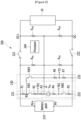
processor 240 turns on the switch SW3 in the state where the switches SW1 and SW2 are off. Then, a current path passing through the resistors R1, R6, and R7 may be formed between the positive terminal PV+ of thebattery pack 210 and the negative terminal PV- of thebattery pack 210, as shown inFIG. 3 . However, since the switches SW1 and SW2 are off, any current path is not formed between the node N1 and the ground terminal of the external device and between the ground terminal and the negative terminal PV-of thebattery pack 210. Therefore, the voltage VPACK of thebattery pack 210 can be divided by the resistors R1, R6, and R7 as shown in Equation 1, whereby the fraction thereof can be output as the voltage VP of the voltage monitoring terminal TV. Theprocessor 240 may measure the voltage VPACK of thebattery pack 210 on the basis of the voltage VP of the voltage monitoring terminal TV.
- In Equation 1, R1, R6, and R7 are the resistance values of the resistors R1, R6, and R7, respectively.
- Now, insulation resistance measurement will be described with reference to
FIG. 4 andFIG. 5 . - Referring to
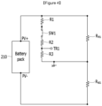
FIG. 4 , theprocessor 240 turns on the switch SW1 in the state where the switch SW2 is off and the switch SW3 is on. In some example embodiments, theprocessor 240 may turn off the switch SW3. By turning on the switch SW1, a current path passing through the resistors R1, R2, and R3 is formed between the positive terminal PV+ of thebattery pack 210 and the ground terminal of the external device. However, since the switch SW2 is off, any current path passing through the resistors R4 and R5 is not formed. In this case, between the positive terminal PV+ of thebattery pack 210 and the ground terminal of the external device, the insulation resistance RPI1 is formed. Therefore, between the positive terminal PV+ of thebattery pack 210 and the ground terminal of the external device, a circuit in which the set of resistors R1, R2, and R3 and the insulation resistance RPI1 are connected in parallel is formed. Further, between the ground terminal and the negative terminal PV- of thebattery pack 210, a circuit in which the insulation resistance RNI1 is connected is formed. In this state, theprocessor 240 receives the voltage V1 of the first insulation resistance monitoring terminal TR1. The relationship between the voltage VPACK of thebattery pack 210 and the voltage V1 of the first insulation resistance monitoring terminal TR1 in the circuit shown inFIG. 4 may be determined as shown in Equation 2. In the case where the switch SW3 is turned on, a current path passing through the resistors R6 and R7 is formed; however, for ease of explanation, it is assumed that the resistance values of the resistors R6 and R7 are so large that the current flowing through the resistors R6 and R7 can be ignored in Equation 2.
- In Equation 2, R1, R2, R3, RPI1, and RNI1 are the resistance values of the resistors R1, R2, and R3 and the resistance values of the resistance RPI1 and RNI1, respectively.
- Referring to
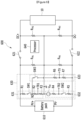
FIG. 5 , theprocessor 240 turns on the switch SW2 in the state where the switch SW1 is off and the switch SW3 is on. In some example embodiments, theprocessor 240 may turn off the switch SW3. By turning on the switch SW2, a current path passing through the voltage source Voc and the resistors R4 and R5 is formed between the ground terminal of the external device and the negative terminal PV- of thebattery pack 210. However, since the switch SW1 is off, any current path passing through the resistors R1, R2, and R3 is not formed. In this case, the insulation resistance RNI1 is formed between the ground terminal and the negative terminal PV- of thebattery pack 210. Therefore, between the ground terminal and the negative terminal PV- of thebattery pack 210, a circuit in which the set of resistors R4 and R5 and the insulation resistance RNI1 are connected in parallel is formed. Further, between the positive terminal PV+ of thebattery pack 210 and the ground terminal of the external device, a circuit in which the insulation resistance RPI1 is connected is formed. In this state, theprocessor 240 receives the voltage V2 of the second insulation resistance monitoring terminal TR2. The relationship between the voltage VPACK of thebattery pack 210 and the voltage V2 of the second insulation resistance monitoring terminal TR2 in the circuit shown inFIG. 5 may be determined as shown in Equation 3. In the case where the switch SW3 is turned on, a current path passing through the resistors R6 and R7 is formed; however, for ease of explanation, it is assumed that the resistance values of the resistors R6 and R7 are so large that the current flowing through the resistors R6 and R7 can be ignored in Equation 3.
- In Equation 3, R4, R5, RPI1, and RNI1 are the resistance values of the resistors R4 and R5 and the resistance values of the resistance RPI1 and RNI1, respectively.
- The
processor 240 calculates the resistance values of the insulation resistance RPI1 and RNI1 on the basis of the voltage V1 of the first insulation resistance monitoring terminal TR1, the voltage V2 of the second insulation resistance monitoring terminal TR2, and the voltage VPACK of thebattery pack 210. Theprocessor 240 may calculate the resistance values of the insulation resistance RPI1 and RNI1 on the basis of Equations 2 and 3 as shown in Equations 4 and 5.

- In Equations 4 and 5, A, B, C, and D can be defined as shown in Equations 6, 7, 8, and 9, respectively.


- Meanwhile, in the case where the
main switches FIG. 4 andFIG. 5 , the insulation resistance RPI2 of the external device is connected in parallel with the insulation resistance RPI1 of the battery unit, and the insulation resistance RNI2 of the external device is connected in parallel with the insulation resistance RNI1 of the battery unit. Therefore, theprocessor 240 may calculate the resistance values of the insulation resistance RPI1 and RPI2 connected in parallel through the process described with reference to Equations 2 to 9 and the resistance values of the insulation resistance RNI1 and RNI2 connected in parallel. Theprocessor 240 may calculate the resistance values of the insulation resistance RPI2 and RNI2 of the external device on the basis of the resistance values of the insulation resistance RPI1 and RNI1 measured when themain switches main switches - According to the example embodiments described above, the insulation
resistance monitoring circuits voltage monitoring circuit 233 may share the resistor R1, whereby it is possible to reduce the cost of the battery management system as compared to the case where the insulationresistance monitoring circuits voltage monitoring circuit 233 may have separate resistors connected to the positive terminal PV+ of thebattery pack 210. -
FIG. 6 is a drawing illustrating an example of a battery unit according to another example embodiment. - Referring to
FIG. 6 , abattery unit 600 includes abattery pack 610,main switches monitoring circuit 630, and aprocessor 640. Thebattery pack 610, themain switches processor 640 are similar to thebattery pack 110, themain switches processor 140 described with reference toFIG. 1 , so a description thereof will not be made. Themonitoring circuit 630 includes a first insulationresistance monitoring circuit 631, a second insulationresistance monitoring circuit 632, and avoltage monitoring circuit 633. Themonitoring circuit 630 is similar to themonitoring circuit 230 described with reference toFIG. 2 , and the differences between them will be described. - A node N2 in the first insulation
resistance monitoring circuit 631 to which thevoltage monitoring circuit 633 is connected may be the contact point of the switch SW1 and the resistor R2. In other words, in thevoltage monitoring circuit 633, the switch SW3 may be connected to the second terminal N2 of the switch SW1 of the first insulationresistance monitoring circuit 231. In some example embodiments, the first terminal of the switch SW3 may be connected to the second terminal N2 of the switch SW1, and the resistor R6 may be connected between the second terminal of the switch SW3 and the voltage monitoring terminal TV. - In this case, in order to measure the voltage of the
battery pack 610, theprocessor 640 turns on the switches SW1 and SW3 when the switch SW2 is off. By turning on the switches SW1 and SW3, a current path passing through the resistors R1, R2, and R3 is formed between the positive terminal PV+ of thebattery pack 610 and the ground terminal of the external device. In order to measure the insulation resistance RPI1, RNI1, RPI2, and RNI2, theprocessor 640 performs the same operation as that of theprocessor 240 shown inFIG. 2 . -
FIG. 7 is a drawing illustrating an example of a battery unit according to another example embodiment of the present invention. - Referring to
FIG. 7 , abattery unit 700 includes abattery pack 710,main switches monitoring circuit 730, and aprocessor 740. Thebattery pack 710, themain switches processor 740 are similar to thebattery pack 110, themain switches processor 140 described with reference toFIG. 1 , so a description thereof will not be made. Themonitoring circuit 730 includes a first insulationresistance monitoring circuit 731, a second insulationresistance monitoring circuit 732, and avoltage monitoring circuit 733. Themonitoring circuit 730 is similar to themonitoring circuit 230 described with reference toFIG. 2 , and the differences between them will be described. - In the first insulation
resistance monitoring circuit 731, the switch SW1 may be connected between the resistor R2 and the resistor (or the second resistor) R3, and a node N3 in the first insulationresistance monitoring circuit 731 to which thevoltage monitoring circuit 733 is connected may be the contact point of the resistor R2 and the switch SW1. In some example embodiments, the resistor R2 may be connected between one terminal of the resistor R1 and the node N3, and the switch SW1 may be connected between the node N3 and the first insulation resistance monitoring terminal TR1, and the resistor R3 may be connected between the first insulation resistance monitoring terminal TR1 and the ground terminal of the external device. The switch SW3 in thevoltage monitoring circuit 733 may be connected to the node N3. In some example embodiments, thevoltage monitoring circuit 733 may not include the resistor R6, and the switch SW3 may be connected between the node N3 and the voltage monitoring terminal TV. In some example embodiments, the resistors R1 and R2 of the first insulationresistance monitoring circuit 731 may be replaced with one resistor. - In this case, in order to measure the voltage of the
battery pack 710 and the insulation resistance, theprocessor 740 performs the same operation as that of theprocessor 240 shown inFIG. 2 . - In some example embodiments, the switch SW3 of the
voltage monitoring circuit FIG. 2 ,FIG. 6 , andFIG. 7 , whereby it is possible to further reduce the cost of the battery management system. In some example embodiments, a resistor having a large resistance value may be used in thevoltage monitoring circuit voltage monitoring circuit - While this invention has been described in connection with what is presently considered to be practical example embodiments, it is to be understood that the invention is not limited to the disclosed embodiments. On the contrary, it is intended to cover various modifications and equivalent arrangements included within the spirit and scope of the appended claims.
Claims (18)
- A battery unit which is connectable to an external device, comprising:a battery pack;a first resistor connected between a positive terminal of the battery pack and a node;a second resistor arranged to be connected between the node and a ground terminal of the external device when the battery unit is connected to the external device;a third resistor and a fourth resistor arranged to be connected between the ground terminal and a negative terminal of the battery pack when the battery unit is connected to the external device;a fifth resistor connected between the node and the negative terminal of the battery pack; anda processor configured to measure a voltage of the battery pack based on a voltage of a first terminal of the fifth resistor, and measure a first insulation resistance formed between the positive terminal of the battery pack and the ground terminal and a second insulation resistance formed between the negative terminal of the battery pack and the ground terminal based on a voltage of a first terminal of the second resistor and a voltage of a contact point of the third resistor and the fourth resistor.
- The battery unit of claim 1, further comprising:
A DC voltage source arranged to be connected between the ground terminal and the negative terminal of the battery pack on a path where the third resistor and the fourth resistor are positioned. - The battery unit of claim 1, further comprising:A first switch and a sixth resistor arranged to be connected between the node and the ground terminal on a path where the second resistors are positioned;A second switch arranged to be connected between the ground terminal and the negative terminal of the battery pack on a path where the third resistor and the fourth resistor are positioned; anda seventh resistor connected between the node and the negative terminal of the battery pack on a path where the fifth resistor is positioned.
- The battery unit of claim 3, further comprising:
a third switch connected between the node and the negative terminal of the battery pack on a path where the fifth resistor and the seventh resistor are positioned. - The battery unit of claim 3, wherein:
the processor is configured to perform the following:measuring the voltage of the battery pack based on a voltage computed by dividing the voltage using resistances of the fifth resistor and the seventh resistor, when the first switch and the second switch are off; andmeasuring the first insulation resistance and the second insulation resistance based on the voltage of the battery pack, a voltage computed by dividing the voltage using resistances of the second resistor and the sixth resistor when the first switch is on and the second switch are off, and a voltage computed by dividing the voltage using resistances of the third resistor and the fourth resistor when the first switch is off and the second switch are on. - The battery unit of claim 1, further comprising:a first switch connected between the positive terminal of the battery pack and the node on a path where the first resistor is positioned;a sixth resistor connected between the node and the ground terminal on a path where the second resistor is positioned;a second switch arranged to be connected between the ground terminal and the negative terminal of the battery pack on a path where the third resistor and the fourth resistor are positioned; anda seventh resistor connected between the node and the negative terminal of the battery pack on a path where the fifth resistor is positioned.
- The battery unit of claim 6, further comprising:
a third switch connected between the node and the negative terminal of the battery pack on a path where the fifth resistor and the seventh resistor are positioned. - The battery unit of claim 6, wherein:
the processor performs the following:measuring the voltage of the battery pack based on a voltage computed by dividing the voltage using resistances of the fifth resistor and the seventh resistor, when the first switch is on and the second switch is off; andmeasuring the first insulation resistance and the second insulation resistance based on the voltage of the battery pack, a voltage computed by dividing the voltage using resistances of the second resistor and the sixth resistor when the first switch is on and the second switch is off, and a voltage computed by dividing the voltage using resistances of the third resistor and the fourth resistor when the first switch is off and the second switch is on. - The battery unit of claim 1, further comprising:A first switch arranged to be connected between the node and the ground terminal on a path where the second resistor is positioned; andA second switch arranged to be connected between the ground terminal and the negative terminal of the battery pack on a path where the third resistor and the fourth resistor are positioned.
- The battery unit of claim 9, further comprising:
a third switch connected between the node and the negative terminal of the battery pack on a path where the fifth resistor is positioned. - The battery unit of claim 9, wherein:
The processor is configured to:measure the voltage of the battery pack based on a voltage computed by dividing the voltage using resistances of the first resistor and the fifth resistor, when the first switch and the second switch are off; andmeasure the first insulation resistance and the second insulation resistance based on the voltage of the battery pack, a voltage computed by dividing the voltage using resistances of the first resistor and the second resistor when the first switch is on and the second switch is off, and a voltage computed by dividing the voltage using resistances of the third resistor and the fourth resistor when the first switch is off and the second switch is on. - A battery management system of a battery unit connectable to an external device and including a battery pack, comprising:A first insulation resistance monitoring circuit that includes a first monitoring terminal, and a first resistor connected between a positive terminal of the battery pack and a node, and is arranged to be connected between the positive terminal of the battery pack and a ground terminal of the external device;A second insulation resistance monitoring circuit that includes a second monitoring terminal, and is arranged to be connected between the ground terminal and a negative terminal of the battery pack;a voltage monitoring circuit that includes a third monitoring terminal, and is connected between the node and the negative terminal of the battery pack; anda processor configured to measure a voltage of the battery pack based on a voltage of the third monitoring terminal, and measures a first insulation resistance formed between the positive terminal of the battery pack and the ground terminal and a second insulation resistance formed between the negative terminal of the battery pack and the ground terminal, based on a voltage of the first monitoring terminal and a voltage of the second monitoring terminal.
- The battery management system of claim 12, wherein:the first insulation resistance monitoring circuit further includes a first switch, a second resistor, and a third resistor connected between the node and the ground terminal, and the first monitoring terminal being connected to a contact point of the second resistor and the third resistor, andthe second insulation resistance monitoring circuit further includes a DC voltage source, a second switch, a fourth resistor, and a fifth resistor connected between the ground terminal and the negative terminal of the battery pack, and the second monitoring terminal being connected to a contact point of the fourth resistor and the fifth resistor, andthe voltage monitoring circuit further includes a sixth resistor and a seventh resistor connected between the node and the negative terminal of the battery pack, and the third monitoring terminal being connected to a contact point of the sixth resistor and the seventh resistor.
- The battery management system of claim 13, wherein:
the processor is configured to:measure the voltage of the battery pack based on the voltage of the third monitoring terminal when the first switch and the second switch are off; andmeasure the first insulation resistance and the second insulation resistance based on the voltage of the battery pack, the voltage of the first monitoring terminal measured when the first switch is on and the second switch is off, and the voltage of the second monitoring terminal measured when the first switch is off and the second switch is on. - The battery management system of claim 12, wherein:the first insulation resistance monitoring circuit further includes a second resistor and a third resistor arranged to be connected between the node and the ground terminal, and a first switch connected between the positive terminal of the battery pack and the node on a path formed by the first resistor, the first monitoring terminal being connected to a contact point of the second resistor and the third resistor, andthe second insulation resistance monitoring circuit further includes a DC voltage source, a second switch, a fourth resistor, and a fifth resistor arranged to be connected between the ground terminal and the negative terminal of the battery pack, the second monitoring terminal being connected to a contact point of the fourth resistor and the fifth resistor, andthe voltage monitoring circuit further includes a sixth resistor and a seventh resistor connected between the node and the negative terminal of the battery pack, the third monitoring terminal being connected to a contact point of the sixth resistor and the seventh resistor.
- The battery management system of claim 15, wherein:
the processor is configured to :measuring the voltage of the battery pack based on the voltage of the third monitoring terminal, when the first switch is on and the second switch is off; andmeasuring the first insulation resistance and the second insulation resistance based on the voltage of the battery pack, the voltage of the first monitoring terminal measured when the first switch is on and the second switch is off, and the voltage of the second monitoring terminal measured when the first switch is off and the second switch is on. - The battery management system of claim 12, wherein:the first insulation resistance monitoring circuit further includes a first switch and a second resistor connected between the node and the ground terminal, the first monitoring terminal being connected to a contact point of the first resistor and the second resistor, andthe second insulation resistance monitoring circuit further includes a DC voltage source, a second switch, a third resistor, and a fourth resistor connected between the ground terminal and the negative terminal of the battery pack, the second monitoring terminal being connected to a contact point of the third resistor and the fourth resistor, andthe voltage monitoring circuit further includes a fifth resistor connected between the node and the negative terminal of the battery pack, the third monitoring terminal being connected to a contact point of the first resistor and the fifth resistor.
- The battery management system of claim 17, wherein:
the processor is configured to:measure the voltage of the battery pack based on the voltage of the third monitoring terminal when the first switch and the second switch are off; andmeasure the first insulation resistance and the second insulation resistance based on the voltage of the battery pack, the voltage of the first monitoring terminal measured when the first switch is on and the second switch is off, and the voltage of the second monitoring terminal measured when the first switch is off and the second switch is on.
Applications Claiming Priority (2)
| Application Number | Priority Date | Filing Date | Title |
|---|---|---|---|
| KR1020220002135A KR102945059B1 (en) | 2022-01-06 | 2022-01-06 | Battery apparatus and battery management system for measuring insulation resistance |
| PCT/KR2023/000250 WO2023132670A1 (en) | 2022-01-06 | 2023-01-05 | Battery device and battery management system for insulation resistance measurement |
Publications (2)
| Publication Number | Publication Date |
|---|---|
| EP4403944A1 true EP4403944A1 (en) | 2024-07-24 |
| EP4403944A4 EP4403944A4 (en) | 2025-01-08 |
Family
ID=87073956
Family Applications (1)
| Application Number | Title | Priority Date | Filing Date |
|---|---|---|---|
| EP23737418.6A Pending EP4403944A4 (en) | 2022-01-06 | 2023-01-05 | BATTERY DEVICE AND BATTERY MANAGEMENT SYSTEM FOR INSULATION RESISTANCE MEASUREMENT |
Country Status (6)
| Country | Link |
|---|---|
| US (1) | US20250027984A1 (en) |
| EP (1) | EP4403944A4 (en) |
| JP (1) | JP7732656B2 (en) |
| KR (1) | KR102945059B1 (en) |
| CN (1) | CN118251601A (en) |
| WO (1) | WO2023132670A1 (en) |
Families Citing this family (1)
| Publication number | Priority date | Publication date | Assignee | Title |
|---|---|---|---|---|
| KR20250035261A (en) * | 2023-09-05 | 2025-03-12 | 주식회사 엘지에너지솔루션 | Isolation diagnostic circuit and battery system comprising the same |
Family Cites Families (13)
| Publication number | Priority date | Publication date | Assignee | Title |
|---|---|---|---|---|
| JP2006220520A (en) | 2005-02-10 | 2006-08-24 | Honda Motor Co Ltd | Insulation resistance measuring apparatus and method for non-grounded DC power supply |
| JP5552218B2 (en) | 2008-07-08 | 2014-07-16 | 株式会社日立製作所 | Power supply |
| WO2013147494A1 (en) | 2012-03-26 | 2013-10-03 | 주식회사 엘지화학 | Device and method for measuring insulation resistance of battery |
| PL2796887T3 (en) | 2012-03-27 | 2020-05-18 | Lg Chem, Ltd. | Isolation resistance measurement apparatus having fault self-diagnosis function and fault self-diagnosing method using the same |
| KR102042756B1 (en) * | 2016-10-10 | 2019-11-08 | 주식회사 엘지화학 | Diagnostic appratus and power system including the same |
| KR102270232B1 (en) * | 2017-12-11 | 2021-06-25 | 주식회사 엘지에너지솔루션 | Method and apparatus for diagnosing fault of positive contactor of battery pack |
| KR102270233B1 (en) * | 2017-12-12 | 2021-06-25 | 주식회사 엘지에너지솔루션 | Method and apparatus for diagnosing fault of negative contactor of battery pack |
| KR102099414B1 (en) * | 2018-11-22 | 2020-04-09 | 현대오트론 주식회사 | Apparatus and method for measuring isolation resistance using sensing integrated circuit |
| KR102672495B1 (en) * | 2019-03-15 | 2024-06-07 | 에스케이온 주식회사 | Apparatus for measuring insulation resistance |
| KR102731446B1 (en) * | 2019-11-18 | 2024-11-15 | 주식회사 엘지에너지솔루션 | Apparatus for estimating Insulation Resistance and Battery System using the same |
| KR102786968B1 (en) * | 2019-12-10 | 2025-03-26 | 에스케이온 주식회사 | Apparatus for measuring insulation resistance |
| KR102804359B1 (en) * | 2020-04-13 | 2025-05-09 | 에스케이온 주식회사 | Apparatus for measuring insulation resistance |
| DE102020208149A1 (en) | 2020-06-30 | 2021-12-30 | Te Connectivity Germany Gmbh | Module connector |
-
2022
- 2022-01-06 KR KR1020220002135A patent/KR102945059B1/en active Active
-
2023
- 2023-01-05 JP JP2024522683A patent/JP7732656B2/en active Active
- 2023-01-05 EP EP23737418.6A patent/EP4403944A4/en active Pending
- 2023-01-05 CN CN202380014491.2A patent/CN118251601A/en active Pending
- 2023-01-05 WO PCT/KR2023/000250 patent/WO2023132670A1/en not_active Ceased
- 2023-01-05 US US18/711,243 patent/US20250027984A1/en active Pending
Also Published As
| Publication number | Publication date |
|---|---|
| WO2023132670A1 (en) | 2023-07-13 |
| CN118251601A (en) | 2024-06-25 |
| JP7732656B2 (en) | 2025-09-02 |
| EP4403944A4 (en) | 2025-01-08 |
| JP2024539045A (en) | 2024-10-28 |
| KR102945059B1 (en) | 2026-03-26 |
| KR20230106346A (en) | 2023-07-13 |
| US20250027984A1 (en) | 2025-01-23 |
Similar Documents
| Publication | Publication Date | Title |
|---|---|---|
| EP4067922B1 (en) | Battery apparatus, battery management system, and method for diagnosing connection status | |
| JP4186916B2 (en) | Battery pack management device | |
| EP2322375B1 (en) | Apparatus and method for controlling a switch unit between battery pack and a load, and battery pack and battery management apparatus including the apparatus | |
| US9252624B2 (en) | Battery control device and battery system | |
| US7692430B2 (en) | Power control unit | |
| US10071646B2 (en) | Electrical system and method for operating an electrical system | |
| US10562474B2 (en) | Vehicle electrical system | |
| US20120306468A1 (en) | Energy Storage System and Method for Operating Same | |
| EP2993074A1 (en) | Battery pack and hybrid vehicle including the battery pack | |
| US20230106428A1 (en) | Switch systems for rechargeable battery arrays | |
| JP2009286292A (en) | Vehicular power supply device | |
| KR101502965B1 (en) | Power supplying apparatus for electronic device | |
| JP2022545352A (en) | Low voltage cell detection method and battery management system providing the method | |
| EP4403944A1 (en) | Battery device and battery management system for insulation resistance measurement | |
| EP4401272B1 (en) | Battery device, battery system and diagnosis method | |
| US20250007012A1 (en) | Battery device and balancing method | |
| US12523705B2 (en) | Battery apparatus and current sensor diagnosis method | |
| CN118894012A (en) | Energy transfer between mismatched battery systems | |
| EP4700407A1 (en) | Battery management system, battery device, and method for diagnosing cell voltage measurement line | |
| EP4303600A1 (en) | Voltage determination circuit | |
| KR20210061100A (en) | Battery apparatus and drift fault diagnosis method | |
| JP2008128845A (en) | Voltage measuring device and electric vehicle | |
| KR20260053636A (en) | Battery apparatus and diagnosis method thereof | |
| JP2019074348A (en) | Secondary battery state detection device and secondary battery state detection method |
Legal Events
| Date | Code | Title | Description |
|---|---|---|---|
| STAA | Information on the status of an ep patent application or granted ep patent |
Free format text: STATUS: THE INTERNATIONAL PUBLICATION HAS BEEN MADE |
|
| PUAI | Public reference made under article 153(3) epc to a published international application that has entered the european phase |
Free format text: ORIGINAL CODE: 0009012 |
|
| STAA | Information on the status of an ep patent application or granted ep patent |
Free format text: STATUS: REQUEST FOR EXAMINATION WAS MADE |
|
| 17P | Request for examination filed |
Effective date: 20240416 |
|
| AK | Designated contracting states |
Kind code of ref document: A1 Designated state(s): AL AT BE BG CH CY CZ DE DK EE ES FI FR GB GR HR HU IE IS IT LI LT LU LV MC ME MK MT NL NO PL PT RO RS SE SI SK SM TR |
|
| A4 | Supplementary search report drawn up and despatched |
Effective date: 20241206 |
|
| RIC1 | Information provided on ipc code assigned before grant |
Ipc: G01R 31/396 20190101ALI20241202BHEP Ipc: G01R 31/385 20190101ALI20241202BHEP Ipc: G01R 15/04 20060101ALI20241202BHEP Ipc: G01R 31/3835 20190101ALI20241202BHEP Ipc: G01R 27/08 20060101ALI20241202BHEP Ipc: G01R 27/02 20060101ALI20241202BHEP Ipc: G01R 31/389 20190101AFI20241202BHEP |
|
| DAV | Request for validation of the european patent (deleted) | ||
| DAX | Request for extension of the european patent (deleted) | ||
| STAA | Information on the status of an ep patent application or granted ep patent |
Free format text: STATUS: EXAMINATION IS IN PROGRESS |
|
| 17Q | First examination report despatched |
Effective date: 20250630 |