EP4403928A1 - Current sensor with diagnostic feature - Google Patents
Current sensor with diagnostic feature Download PDFInfo
- Publication number
- EP4403928A1 EP4403928A1 EP24152328.1A EP24152328A EP4403928A1 EP 4403928 A1 EP4403928 A1 EP 4403928A1 EP 24152328 A EP24152328 A EP 24152328A EP 4403928 A1 EP4403928 A1 EP 4403928A1
- Authority
- EP
- European Patent Office
- Prior art keywords
- current sensor
- magnetic field
- coil
- current
- busbar
- Prior art date
- Legal status (The legal status is an assumption and is not a legal conclusion. Google has not performed a legal analysis and makes no representation as to the accuracy of the status listed.)
- Pending
Links
Images

Classifications
-
- G—PHYSICS
- G01—MEASURING; TESTING
- G01R—MEASURING ELECTRIC VARIABLES; MEASURING MAGNETIC VARIABLES
- G01R15/00—Details of measuring arrangements of the types provided for in groups G01R17/00 - G01R29/00, G01R33/00 - G01R33/26 or G01R35/00
- G01R15/14—Adaptations providing voltage or current isolation, e.g. for high-voltage or high-current networks
- G01R15/20—Adaptations providing voltage or current isolation, e.g. for high-voltage or high-current networks using galvano-magnetic devices, e.g. Hall-effect devices, i.e. measuring a magnetic field via the interaction between a current and a magnetic field, e.g. magneto resistive or Hall effect devices
-
- G—PHYSICS
- G01—MEASURING; TESTING
- G01R—MEASURING ELECTRIC VARIABLES; MEASURING MAGNETIC VARIABLES
- G01R15/00—Details of measuring arrangements of the types provided for in groups G01R17/00 - G01R29/00, G01R33/00 - G01R33/26 or G01R35/00
- G01R15/14—Adaptations providing voltage or current isolation, e.g. for high-voltage or high-current networks
- G01R15/20—Adaptations providing voltage or current isolation, e.g. for high-voltage or high-current networks using galvano-magnetic devices, e.g. Hall-effect devices, i.e. measuring a magnetic field via the interaction between a current and a magnetic field, e.g. magneto resistive or Hall effect devices
- G01R15/202—Adaptations providing voltage or current isolation, e.g. for high-voltage or high-current networks using galvano-magnetic devices, e.g. Hall-effect devices, i.e. measuring a magnetic field via the interaction between a current and a magnetic field, e.g. magneto resistive or Hall effect devices using Hall-effect devices
-
- G—PHYSICS
- G01—MEASURING; TESTING
- G01R—MEASURING ELECTRIC VARIABLES; MEASURING MAGNETIC VARIABLES
- G01R15/00—Details of measuring arrangements of the types provided for in groups G01R17/00 - G01R29/00, G01R33/00 - G01R33/26 or G01R35/00
- G01R15/14—Adaptations providing voltage or current isolation, e.g. for high-voltage or high-current networks
- G01R15/20—Adaptations providing voltage or current isolation, e.g. for high-voltage or high-current networks using galvano-magnetic devices, e.g. Hall-effect devices, i.e. measuring a magnetic field via the interaction between a current and a magnetic field, e.g. magneto resistive or Hall effect devices
- G01R15/207—Constructional details independent of the type of device used
-
- G—PHYSICS
- G01—MEASURING; TESTING
- G01R—MEASURING ELECTRIC VARIABLES; MEASURING MAGNETIC VARIABLES
- G01R19/00—Arrangements for measuring currents or voltages or for indicating presence or sign thereof
- G01R19/0092—Measuring current only
-
- G—PHYSICS
- G01—MEASURING; TESTING
- G01R—MEASURING ELECTRIC VARIABLES; MEASURING MAGNETIC VARIABLES
- G01R33/00—Arrangements or instruments for measuring magnetic variables
- G01R33/02—Measuring direction or magnitude of magnetic fields or magnetic flux
Definitions
- the disclosure relates generally to the field of circuit protection devices and, more particularly, to a current sensor with a diagnostic feature for in-situ feedback.
- An apparatus may include a current sensor coupled to a busbar, the current sensor comprising a coil, wherein a current flowing through the busbar generates a first magnetic field detectable by the current sensor, wherein the coil is operable to generate a second magnetic field, and wherein by orienting the coil, the current sensor will receive part of the second magnetic field, superposed to the first magnetic field.
- embodiments of the present disclosure provide for in-situ verification that a current sensor remains functional and retains calibration.
- the sensor status (i.e., working / not working) and loss of calibration may be reported to a superordinated control system, which can take appropriate action.
- FIG. 1 illustrates a current sensor assembly 100 (hereinafter “assembly”) according to embodiments of the present disclosure.
- the assembly 100 may be used with a Hall or TMR sensor (not shown).
- the assembly 100 may include a current sensor 102 coupled to a busbar 104, the current sensor 102 including a coil 108 operable to generate a magnetic field Bdiag.
- the busbar 104 may be made of copper or other electrically conductive material.
- the current sensor 102 may be coupled to a PCB, wherein the main conductor of the assembly 100 may be a PCB trace, and the diagnostic coil could be build-up by traces on multiple layers of the PCB.
- the current Isense flowing through the busbar 104 generates a magnetic field Bsense, which is detected by the current sensor 102.
- a value representing the magnetic field may be delivered to a controller 105, which is operable with the current sensor 102.
- the current sensor 102 will receive part of this magnetic field, superposed to the Bsense magnetic field.
- the coil 108 may generally be oriented orthogonal/perpendicular to the direction of current Isense flowing through the busbar 104.
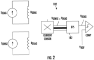
- the current sensor 102 receives the sum of Bsense + Bdiag, and converts it to a voltage Vsense + Vdiag.
- a discriminator (DIS) 112 removes Vsense, keeping Viag only. Given a certain invariable position of the coil 108 relative to the current sensor 102, and by setting an appropriate threshold level VREF, it is possible to determine if the current sensor 102 is operating properly by comparison.
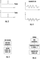
- FIG. 3 demonstrates the relationship between current (I) and magnetic field (B) over time. More specifically, the current Idiag can be a pulsed current, with a certain time duration. In this case, the DIS can separate Vdiag from Vsense because the time for Vsense is deterministic referenced to Idiag. Diagnostics can be run without sense current (e.g., vehicle parked, part of the initialization sequence) or with sense current (e.g., vehicle driving)
- the current Idiag can be a periodic current (i.e. sinusoidal), with a certain frequency.
- the DIS can separate Vdiag from Vsense because the frequency for Vsense is deterministic referenced to Idiag.
- diagnostics can be run without sense current (e.g., vehicle parked, part of the initialization sequence) or with sense current (e.g., vehicle driving).
- FIGs. 5-6 demonstrate that the diagnostic may be run at the end of the manufacturing process ("Init (EoLine)"), once the relative position of the diagnostic coil referenced to the current sensor is fixed. Vsense_ref and Isense_ref are recorded. Every time the diagnostic is run in a normal mode, it is possible to check the calibration status by comparing the Vsense with the recorded value (e.g., after applying some corrections depending on other factors such as Isense, T, ).
- the terms “substantial” or “substantially,” as well as the terms “approximate” or “approximately,” can be used interchangeably in some embodiments, and can be described using any relative measures acceptable by one of ordinary skill in the art. For example, these terms can serve as a comparison to a reference parameter, to indicate a deviation capable of providing the intended function. Although non-limiting, the deviation from the reference parameter can be, for example, in an amount of less than 1%, less than 3%, less than 5%, less than 10%, less than 15%, less than 20%, and so on.
Landscapes
- Physics & Mathematics (AREA)
- General Physics & Mathematics (AREA)
- Condensed Matter Physics & Semiconductors (AREA)
- Measuring Instrument Details And Bridges, And Automatic Balancing Devices (AREA)
- Measurement Of Current Or Voltage (AREA)
Abstract
Provided herein are approaches for improving performance of current sensors. In some embodiments, an apparatus may include a current sensor coupled to a busbar, the current sensor comprising a coil, wherein a current flowing through the busbar generates a first magnetic field detectable by the current sensor, wherein the coil is operable to generate a second magnetic field, and wherein by orienting the coil, the current sensor will receive part of the second magnetic field, superposed to the first magnetic field.
Description
- The disclosure relates generally to the field of circuit protection devices and, more particularly, to a current sensor with a diagnostic feature for in-situ feedback.
- Current sensors are often used in overcurrent protection devices, including in short-circuit protection devices. These devices are used as safety elements in critical applications, such as electric vehicles (EV). Oftentimes, current sensors are factory calibrated or compensated. However, prior art approaches lack effective in-situ solutions to periodically check if the current sensor is still operational and calibrated.
- It is with respect to this and other deficiencies of the prior art that the current disclosure is provided.
- The Summary is provided to introduce a selection of concepts in a simplified form, the concepts further described below in the Detailed Description. The Summary is not intended to identify key features or essential features of the claimed subject matter, nor is the Summary intended as an aid in determining the scope of the claimed subject matter.
- In one approach according to the present disclosure, An apparatus may include a current sensor coupled to a busbar, the current sensor comprising a coil, wherein a current flowing through the busbar generates a first magnetic field detectable by the current sensor, wherein the coil is operable to generate a second magnetic field, and wherein by orienting the coil, the current sensor will receive part of the second magnetic field, superposed to the first magnetic field.
- The accompanying drawings illustrate exemplary approaches of the disclosed embodiments so far devised for the practical application of the principles thereof, and in which:
-
FIG. 1 depicts a current sensor assembly according to embodiments of the present disclosure; -
FIG. 2 depicts a circuit diagram of the current sensor according to embodiments of the present disclosure; -
FIGs. 3-4 depict current and magnetic field of the current sensor as a function of time, according to embodiments of the present disclosure; and -
FIGs. 5-6 depict diagnostic flowcharts according to embodiments of the present disclosure. - The drawings are not necessarily to scale. The drawings are merely representations, not intended to portray specific parameters of the disclosure. The drawings are intended to depict typical embodiments of the disclosure, and therefore should not be considered as limiting in scope. In the drawings, like numbering represents like elements.
- Furthermore, certain elements in some of the figures may be omitted, or illustrated not-to-scale, for illustrative clarity. Furthermore, for clarity, some reference numbers may be omitted in certain drawings.
- Sensors, devices, and methods in accordance with the present disclosure will now be described more fully hereinafter with reference to the accompanying drawings. The sensors, devices, and methods may be embodied in many different forms and should not be construed as being limited to the embodiments set forth herein. Rather, these embodiments are provided so that this disclosure will be thorough and complete, and will fully convey the scope of the system and method to those skilled in the art.
- As will be described herein, embodiments of the present disclosure provide for in-situ verification that a current sensor remains functional and retains calibration. The sensor status (i.e., working / not working) and loss of calibration may be reported to a superordinated control system, which can take appropriate action.
-
FIG. 1 illustrates a current sensor assembly 100 (hereinafter "assembly") according to embodiments of the present disclosure. Although non-limiting, theassembly 100 may be used with a Hall or TMR sensor (not shown). Theassembly 100 may include acurrent sensor 102 coupled to abusbar 104, thecurrent sensor 102 including acoil 108 operable to generate a magnetic field Bdiag. Thebusbar 104 may be made of copper or other electrically conductive material. In an alternative embodiment, thecurrent sensor 102 may be coupled to a PCB, wherein the main conductor of theassembly 100 may be a PCB trace, and the diagnostic coil could be build-up by traces on multiple layers of the PCB. - During use, the current Isense flowing through the
busbar 104 generates a magnetic field Bsense, which is detected by thecurrent sensor 102. A value representing the magnetic field may be delivered to acontroller 105, which is operable with thecurrent sensor 102. By properly orienting thecoil 108, thecurrent sensor 102 will receive part of this magnetic field, superposed to the Bsense magnetic field. As shown, thecoil 108 may generally be oriented orthogonal/perpendicular to the direction of current Isense flowing through thebusbar 104. - As shown in
FIG. 2 , thecurrent sensor 102, together with thecontroller 105, receives the sum of Bsense + Bdiag, and converts it to a voltage Vsense + Vdiag. In some embodiments, a discriminator (DIS) 112 removes Vsense, keeping Viag only. Given a certain invariable position of thecoil 108 relative to thecurrent sensor 102, and by setting an appropriate threshold level VREF, it is possible to determine if thecurrent sensor 102 is operating properly by comparison. -
FIG. 3 demonstrates the relationship between current (I) and magnetic field (B) over time. More specifically, the current Idiag can be a pulsed current, with a certain time duration. In this case, the DIS can separate Vdiag from Vsense because the time for Vsense is deterministic referenced to Idiag. Diagnostics can be run without sense current (e.g., vehicle parked, part of the initialization sequence) or with sense current (e.g., vehicle driving) - In
FIG. 4 , the current Idiag can be a periodic current (i.e. sinusoidal), with a certain frequency. In this case, the DIS can separate Vdiag from Vsense because the frequency for Vsense is deterministic referenced to Idiag. Again, diagnostics can be run without sense current (e.g., vehicle parked, part of the initialization sequence) or with sense current (e.g., vehicle driving). -
FIGs. 5-6 demonstrate that the diagnostic may be run at the end of the manufacturing process ("Init (EoLine)"), once the relative position of the diagnostic coil referenced to the current sensor is fixed. Vsense_ref and Isense_ref are recorded. Every time the diagnostic is run in a normal mode, it is possible to check the calibration status by comparing the Vsense with the recorded value (e.g., after applying some corrections depending on other factors such as Isense, T, ...). - For the sake of convenience and clarity, terms such as "top," "bottom," "upper," "lower," "vertical," "horizontal," "lateral," and "longitudinal" will be used herein to describe the relative placement and orientation of components and their constituent parts as appearing in the figures. The terminology will include the words specifically mentioned, derivatives thereof, and words of similar import.
- As used herein, an element or operation recited in the singular and proceeded with the word "a" or "an" is to be understood as including plural elements or operations, until such exclusion is explicitly recited. Furthermore, references to "one embodiment" of the present disclosure are not intended as limiting. Additional embodiments may also incorporating the recited features.
- Furthermore, the terms "substantial" or "substantially," as well as the terms "approximate" or "approximately," can be used interchangeably in some embodiments, and can be described using any relative measures acceptable by one of ordinary skill in the art. For example, these terms can serve as a comparison to a reference parameter, to indicate a deviation capable of providing the intended function. Although non-limiting, the deviation from the reference parameter can be, for example, in an amount of less than 1%, less than 3%, less than 5%, less than 10%, less than 15%, less than 20%, and so on.
- While certain embodiments of the disclosure have been described herein, the disclosure is not limited thereto, as the disclosure is as broad in scope as the art will allow and the specification may be read likewise. Therefore, the above description is not to be construed as limiting. Instead, the above description is merely as exemplifications of particular embodiments. Those skilled in the art will envision other modifications within the scope of the claims appended hereto.
Claims (5)
- An apparatus, comprising:
a current sensor coupled to a busbar, the current sensor comprising a coil, wherein a current flowing through the busbar generates a first magnetic field detectable by the current sensor, wherein the coil is operable to generate a second magnetic field, and wherein by orienting the coil, the current sensor will receive part of the second magnetic field, superposed to the first magnetic field. - The apparatus of claim 1, wherein the coil is oriented perpendicular to a direction of the current flowing through the busbar.
- The apparatus of claim 1, further comprising a controller operable with the current sensor, the controller operable to:receive the sum of the first and second magnetic fields; andconvert the sum of the first and second magnetic fields to a voltage Vsense + Vdiag, wherein a discriminator removes Vsense, keeping Viag only.
- The apparatus of claim 3, wherein the controller is further operable to determine if the sensor is operating properly given an invariable position of the coil relative to the current sensor, and a selected voltage threshold level.
- A current sensing device, comprising:a busbar; anda current sensor coupled to the busbar, the current sensor comprising a coil, wherein a current flowing through the busbar generates a first magnetic field detectable by the current sensor, wherein the coil is operable to generate a second magnetic field, and wherein by orienting the coil, the current sensor will receive part of the second magnetic field, superposed to the first magnetic field.
Applications Claiming Priority (1)
| Application Number | Priority Date | Filing Date | Title |
|---|---|---|---|
| US202363439442P | 2023-01-17 | 2023-01-17 |
Publications (1)
| Publication Number | Publication Date |
|---|---|
| EP4403928A1 true EP4403928A1 (en) | 2024-07-24 |
Family
ID=89620521
Family Applications (1)
| Application Number | Title | Priority Date | Filing Date |
|---|---|---|---|
| EP24152328.1A Pending EP4403928A1 (en) | 2023-01-17 | 2024-01-17 | Current sensor with diagnostic feature |
Country Status (5)
| Country | Link |
|---|---|
| US (1) | US20240241157A1 (en) |
| EP (1) | EP4403928A1 (en) |
| JP (1) | JP2024101562A (en) |
| KR (1) | KR20240114714A (en) |
| CN (1) | CN118362768A (en) |
Citations (3)
| Publication number | Priority date | Publication date | Assignee | Title |
|---|---|---|---|---|
| WO2008040659A2 (en) * | 2006-09-29 | 2008-04-10 | Siemens Aktiengesellschaft | Method for operating a magnetic field sensor and associated magnetic field sensor |
| US20100301835A1 (en) * | 2009-05-27 | 2010-12-02 | Sae Magnetics (H.K.) Ltd. | Current sensor |
| US20150253412A1 (en) * | 2014-03-05 | 2015-09-10 | Infineon Technologies Ag | Device and current sensor for providing information indicating a safe operation |
Family Cites Families (10)
| Publication number | Priority date | Publication date | Assignee | Title |
|---|---|---|---|---|
| WO2010096367A1 (en) * | 2009-02-17 | 2010-08-26 | Allegro Microsystems, Inc. | Circuits and methods for generating a self-test of a magnetic field sensor |
| WO2010143718A1 (en) * | 2009-06-12 | 2010-12-16 | アルプス・グリーンデバイス株式会社 | Magnetic balance current sensor |
| US8896295B2 (en) * | 2012-04-04 | 2014-11-25 | Allegro Microsystems, Llc | Magnetic field sensor having multiple sensing elements and a programmable misalignment adjustment device for misalignment detection and correction in current sensing and other applications |
| US9081041B2 (en) * | 2012-04-04 | 2015-07-14 | Allegro Microsystems, Llc | High accuracy differential current sensor for applications like ground fault interrupters |
| JP2015198028A (en) * | 2014-04-01 | 2015-11-09 | トヨタ自動車株式会社 | Battery monitoring device |
| JP6607172B2 (en) * | 2016-11-17 | 2019-11-20 | 株式会社デンソー | Current sensor device |
| DE102019203498B3 (en) * | 2019-03-14 | 2020-07-16 | Te Connectivity Germany Gmbh | Passive current sensor with simplified geometry |
| US12044708B2 (en) * | 2019-09-20 | 2024-07-23 | Suzhou Littelfuse Ovs Co., Ltd. | Differential signal current sensor |
| KR20220049166A (en) * | 2020-10-14 | 2022-04-21 | 주식회사 디엔제이테크 | Wheatstone bridge type current sensor |
| DE102021127855A1 (en) * | 2021-06-11 | 2022-12-22 | Methode Electronics Malta Ltd. | Current sensor comprising a magnetic field sensor in a V-shaped arrangement |
-
2024
- 2024-01-16 KR KR1020240006454A patent/KR20240114714A/en not_active Ceased
- 2024-01-16 US US18/413,169 patent/US20240241157A1/en active Pending
- 2024-01-17 JP JP2024005055A patent/JP2024101562A/en active Pending
- 2024-01-17 EP EP24152328.1A patent/EP4403928A1/en active Pending
- 2024-01-17 CN CN202410066372.8A patent/CN118362768A/en active Pending
Patent Citations (3)
| Publication number | Priority date | Publication date | Assignee | Title |
|---|---|---|---|---|
| WO2008040659A2 (en) * | 2006-09-29 | 2008-04-10 | Siemens Aktiengesellschaft | Method for operating a magnetic field sensor and associated magnetic field sensor |
| US20100301835A1 (en) * | 2009-05-27 | 2010-12-02 | Sae Magnetics (H.K.) Ltd. | Current sensor |
| US20150253412A1 (en) * | 2014-03-05 | 2015-09-10 | Infineon Technologies Ag | Device and current sensor for providing information indicating a safe operation |
Also Published As
| Publication number | Publication date |
|---|---|
| CN118362768A (en) | 2024-07-19 |
| US20240241157A1 (en) | 2024-07-18 |
| KR20240114714A (en) | 2024-07-24 |
| JP2024101562A (en) | 2024-07-29 |
Similar Documents
| Publication | Publication Date | Title |
|---|---|---|
| JP5090847B2 (en) | Measuring device, signal processing method and program | |
| US11243274B2 (en) | Magnetic sensor system | |
| EP1479157A1 (en) | Method for the detection of abnormalities of electric motors | |
| US9823309B2 (en) | Method for detecting an electrical fault in a generator assemblage, and means for implementation thereof | |
| DE102015103162B4 (en) | Device and current sensor for providing information indicating safe operation | |
| JP6429153B2 (en) | Shut-off device | |
| WO2009018137A1 (en) | Electric power steering control | |
| JP2010175276A (en) | Magnetic proportion system current sensor | |
| KR20120076320A (en) | Current measuring systems and methods of assembling the same | |
| WO2004109895A2 (en) | Methods and apparatus for fault-tolerant control of electric machines | |
| US20130027022A1 (en) | System for measuring current and method of making same | |
| DE102014219238A1 (en) | Overcurrent detection in the current sensor with Hall sensor | |
| CN100403035C (en) | Circuit system and method for testing a circuit | |
| DE102015204106A1 (en) | Angle sensor assembly with safety mechanism and method for its monitoring | |
| CN109661341A (en) | Humidity in the motor of motor vehicle steering system based on Galvanic potential | |
| KR101916046B1 (en) | Voltage sensor default detecting method | |
| US20240241157A1 (en) | Current sensor with diagnostic feature | |
| US20150349675A1 (en) | Method of estimating voltage of input terminal of inverter and motor control method using the same | |
| WO2013010694A1 (en) | Method and device for monitoring a ground connector | |
| US20010035688A1 (en) | Motor coil-shorting detecting unit | |
| EP2130275B1 (en) | Error recognition in a control unit | |
| JP2010091366A (en) | Magnetic balance current sensor | |
| KR20140079314A (en) | Device and method for monitoring signal levels | |
| US10788535B2 (en) | Method for determining the operating status of a MV switching apparatus of the electromagnetic type | |
| US20200025806A1 (en) | Method and apparatus for detecting current using operational amplifier |
Legal Events
| Date | Code | Title | Description |
|---|---|---|---|
| PUAI | Public reference made under article 153(3) epc to a published international application that has entered the european phase |
Free format text: ORIGINAL CODE: 0009012 |
|
| STAA | Information on the status of an ep patent application or granted ep patent |
Free format text: STATUS: THE APPLICATION HAS BEEN PUBLISHED |
|
| AK | Designated contracting states |
Kind code of ref document: A1 Designated state(s): AL AT BE BG CH CY CZ DE DK EE ES FI FR GB GR HR HU IE IS IT LI LT LU LV MC ME MK MT NL NO PL PT RO RS SE SI SK SM TR |
|
| STAA | Information on the status of an ep patent application or granted ep patent |
Free format text: STATUS: REQUEST FOR EXAMINATION WAS MADE |
|
| 17P | Request for examination filed |
Effective date: 20250123 |