EP4403843A1 - Heat exchange unit and air conditioner - Google Patents
Heat exchange unit and air conditioner Download PDFInfo
- Publication number
- EP4403843A1 EP4403843A1 EP22875433.9A EP22875433A EP4403843A1 EP 4403843 A1 EP4403843 A1 EP 4403843A1 EP 22875433 A EP22875433 A EP 22875433A EP 4403843 A1 EP4403843 A1 EP 4403843A1
- Authority
- EP
- European Patent Office
- Prior art keywords
- refrigerant pipe
- liquid
- refrigerant
- section
- pipe
- Prior art date
- Legal status (The legal status is an assumption and is not a legal conclusion. Google has not performed a legal analysis and makes no representation as to the accuracy of the status listed.)
- Granted
Links
Images




Classifications
-
- F—MECHANICAL ENGINEERING; LIGHTING; HEATING; WEAPONS; BLASTING
- F24—HEATING; RANGES; VENTILATING
- F24F—AIR-CONDITIONING; AIR-HUMIDIFICATION; VENTILATION; USE OF AIR CURRENTS FOR SCREENING
- F24F1/00—Room units for air-conditioning, e.g. separate or self-contained units or units receiving primary air from a central station
- F24F1/0007—Indoor units, e.g. fan coil units
- F24F1/0059—Indoor units, e.g. fan coil units characterised by heat exchangers
-
- F—MECHANICAL ENGINEERING; LIGHTING; HEATING; WEAPONS; BLASTING
- F24—HEATING; RANGES; VENTILATING
- F24F—AIR-CONDITIONING; AIR-HUMIDIFICATION; VENTILATION; USE OF AIR CURRENTS FOR SCREENING
- F24F1/00—Room units for air-conditioning, e.g. separate or self-contained units or units receiving primary air from a central station
- F24F1/0007—Indoor units, e.g. fan coil units
- F24F1/0059—Indoor units, e.g. fan coil units characterised by heat exchangers
- F24F1/0067—Indoor units, e.g. fan coil units characterised by heat exchangers by the shape of the heat exchangers or of parts thereof, e.g. of their fins
-
- F—MECHANICAL ENGINEERING; LIGHTING; HEATING; WEAPONS; BLASTING
- F24—HEATING; RANGES; VENTILATING
- F24F—AIR-CONDITIONING; AIR-HUMIDIFICATION; VENTILATION; USE OF AIR CURRENTS FOR SCREENING
- F24F1/00—Room units for air-conditioning, e.g. separate or self-contained units or units receiving primary air from a central station
- F24F1/0007—Indoor units, e.g. fan coil units
- F24F1/0068—Indoor units, e.g. fan coil units characterised by the arrangement of refrigerant piping outside the heat exchanger within the unit casing
-
- F—MECHANICAL ENGINEERING; LIGHTING; HEATING; WEAPONS; BLASTING
- F24—HEATING; RANGES; VENTILATING
- F24F—AIR-CONDITIONING; AIR-HUMIDIFICATION; VENTILATION; USE OF AIR CURRENTS FOR SCREENING
- F24F1/00—Room units for air-conditioning, e.g. separate or self-contained units or units receiving primary air from a central station
- F24F1/06—Separate outdoor units, e.g. outdoor unit to be linked to a separate room comprising a compressor and a heat exchanger
- F24F1/26—Refrigerant piping
-
- F—MECHANICAL ENGINEERING; LIGHTING; HEATING; WEAPONS; BLASTING
- F24—HEATING; RANGES; VENTILATING
- F24F—AIR-CONDITIONING; AIR-HUMIDIFICATION; VENTILATION; USE OF AIR CURRENTS FOR SCREENING
- F24F1/00—Room units for air-conditioning, e.g. separate or self-contained units or units receiving primary air from a central station
- F24F1/06—Separate outdoor units, e.g. outdoor unit to be linked to a separate room comprising a compressor and a heat exchanger
- F24F1/26—Refrigerant piping
- F24F1/32—Refrigerant piping for connecting the separate outdoor units to indoor units
-
- F—MECHANICAL ENGINEERING; LIGHTING; HEATING; WEAPONS; BLASTING
- F24—HEATING; RANGES; VENTILATING
- F24F—AIR-CONDITIONING; AIR-HUMIDIFICATION; VENTILATION; USE OF AIR CURRENTS FOR SCREENING
- F24F13/00—Details common to, or for air-conditioning, air-humidification, ventilation or use of air currents for screening
- F24F13/20—Casings or covers
-
- F—MECHANICAL ENGINEERING; LIGHTING; HEATING; WEAPONS; BLASTING
- F25—REFRIGERATION OR COOLING; COMBINED HEATING AND REFRIGERATION SYSTEMS; HEAT PUMP SYSTEMS; MANUFACTURE OR STORAGE OF ICE; LIQUEFACTION SOLIDIFICATION OF GASES
- F25B—REFRIGERATION MACHINES, PLANTS OR SYSTEMS; COMBINED HEATING AND REFRIGERATION SYSTEMS; HEAT PUMP SYSTEMS
- F25B39/00—Evaporators; Condensers
- F25B39/02—Evaporators
-
- F—MECHANICAL ENGINEERING; LIGHTING; HEATING; WEAPONS; BLASTING
- F25—REFRIGERATION OR COOLING; COMBINED HEATING AND REFRIGERATION SYSTEMS; HEAT PUMP SYSTEMS; MANUFACTURE OR STORAGE OF ICE; LIQUEFACTION SOLIDIFICATION OF GASES
- F25B—REFRIGERATION MACHINES, PLANTS OR SYSTEMS; COMBINED HEATING AND REFRIGERATION SYSTEMS; HEAT PUMP SYSTEMS
- F25B39/00—Evaporators; Condensers
- F25B39/04—Condensers
-
- F—MECHANICAL ENGINEERING; LIGHTING; HEATING; WEAPONS; BLASTING
- F25—REFRIGERATION OR COOLING; COMBINED HEATING AND REFRIGERATION SYSTEMS; HEAT PUMP SYSTEMS; MANUFACTURE OR STORAGE OF ICE; LIQUEFACTION SOLIDIFICATION OF GASES
- F25B—REFRIGERATION MACHINES, PLANTS OR SYSTEMS; COMBINED HEATING AND REFRIGERATION SYSTEMS; HEAT PUMP SYSTEMS
- F25B41/00—Fluid-circulation arrangements
- F25B41/40—Fluid line arrangements
-
- F—MECHANICAL ENGINEERING; LIGHTING; HEATING; WEAPONS; BLASTING
- F28—HEAT EXCHANGE IN GENERAL
- F28F—DETAILS OF HEAT-EXCHANGE AND HEAT-TRANSFER APPARATUS, OF GENERAL APPLICATION
- F28F19/00—Preventing the formation of deposits or corrosion, e.g. by using filters or scrapers
- F28F19/02—Preventing the formation of deposits or corrosion, e.g. by using filters or scrapers by using coatings, e.g. vitreous or enamel coatings
-
- F—MECHANICAL ENGINEERING; LIGHTING; HEATING; WEAPONS; BLASTING
- F25—REFRIGERATION OR COOLING; COMBINED HEATING AND REFRIGERATION SYSTEMS; HEAT PUMP SYSTEMS; MANUFACTURE OR STORAGE OF ICE; LIQUEFACTION SOLIDIFICATION OF GASES
- F25B—REFRIGERATION MACHINES, PLANTS OR SYSTEMS; COMBINED HEATING AND REFRIGERATION SYSTEMS; HEAT PUMP SYSTEMS
- F25B2339/00—Details of evaporators; Details of condensers
- F25B2339/02—Details of evaporators
-
- F—MECHANICAL ENGINEERING; LIGHTING; HEATING; WEAPONS; BLASTING
- F25—REFRIGERATION OR COOLING; COMBINED HEATING AND REFRIGERATION SYSTEMS; HEAT PUMP SYSTEMS; MANUFACTURE OR STORAGE OF ICE; LIQUEFACTION SOLIDIFICATION OF GASES
- F25B—REFRIGERATION MACHINES, PLANTS OR SYSTEMS; COMBINED HEATING AND REFRIGERATION SYSTEMS; HEAT PUMP SYSTEMS
- F25B2339/00—Details of evaporators; Details of condensers
- F25B2339/04—Details of condensers
-
- F—MECHANICAL ENGINEERING; LIGHTING; HEATING; WEAPONS; BLASTING
- F28—HEAT EXCHANGE IN GENERAL
- F28F—DETAILS OF HEAT-EXCHANGE AND HEAT-TRANSFER APPARATUS, OF GENERAL APPLICATION
- F28F2245/00—Coatings; Surface treatments
Definitions
- the present disclosure relates to a heat exchange unit and an air conditioner.
- Examples of a known heat exchange unit include an indoor unit constituting a part of an air conditioner (see, for example, JP 2013-155892 A (Patent Literature 1)).
- Such an indoor unit includes a casing and a heat exchanger disposed in the casing. A refrigerant is taken in and out of the heat exchanger through a connection pipe.
- connection pipe includes a bent section formed to protrude upward.
- the connection pipe further includes a first refrigerant pipe disposed adjacent to the heat exchanger and a second refrigerant pipe disposed remote from the heat exchanger.
- the first refrigerant pipe is formed of aluminum or an aluminum alloy, while the second refrigerant pipe is formed of copper or a copper alloy.
- Patent Literature 1 JP 2013-155892 A
- the known heat exchange unit therefore has a problem that electrolytic corrosion may develop in the first refrigerant pipe in a manner that depends on a position setting of the connection point between the first refrigerant pipe and the second refrigerant pipe.
- a heat exchange unit of the present disclosure includes:
- the approximate vertical direction means a vertical direction or a direction inclined at an angle of, for example, 20 degrees or less relative to the vertical direction.
- the covering member or the coating film covers the one end of the second refrigerant pipe adjacent to the first refrigerant pipe and the first curved section, so that it is possible to prevent the first refrigerant pipe from suffering electrolytic corrosion.
- the first refrigerant pipe has the other end adjacent to the second refrigerant pipe covered with the covering member or the coating film.
- the covering member or the coating film covers the other end of the second refrigerant pipe adjacent to the first refrigerant pipe, so that it is possible to reduce the possibility that the first refrigerant pipe suffers electrolytic corrosion.
- the second refrigerant pipe has the one end connected to the other end of the first refrigerant pipe through a third refrigerant pipe formed of stainless steel, and the third refrigerant pipe is covered with the covering member or the coating film.
- the covering member or the coating film covers the third refrigerant pipe, so that it is possible to reduce the possibility that the first refrigerant pipe suffers electrolytic corrosion.
- the second curved section of the second refrigerant pipe is covered with the covering member or the coating film.
- the covering member or the coating film covers the second curved section of the second refrigerant pipe, so that it is possible to reduce the possibility that the first refrigerant pipe suffers electrolytic corrosion.
- the second refrigerant pipe includes a bent section that is bent to protrude downward.
- the bent section when the bent section is provided adjacent to the first refrigerant pipe relative to the first section, it is possible to reduce the possibility that the first refrigerant pipe suffers electrolytic corrosion.
- the heat exchange unit according to one aspect of the present disclosure is an indoor unit.
- the heat exchange unit is an indoor unit, so that it is possible to prevent the first refrigerant pipe of the connection pipe of the indoor unit from suffering electrolytic corrosion.
- An air conditioner according to one aspect of the present disclosure includes any one of the above-described heat exchange units.
- the heat exchange unit is provided, so that it is possible to prevent the first refrigerant pipe from suffering electrolytic corrosion.
- Fig. 1 is a diagram illustrating a refrigerant circuit RC provided in an air conditioner of a first embodiment of the present disclosure.
- This air conditioner is of a type in which an outdoor unit 2 is paired one-to-one with an indoor unit 1.
- the indoor unit 1 is an example of the heat exchange unit.
- the air conditioner includes the indoor unit 1 and the outdoor unit 2 connected to the indoor unit 1 via the refrigerant circuit RC.
- the refrigerant circuit RC includes a compressor 11, a four-way switching valve 12, an outdoor heat exchanger 13, an electric expansion valve 14, an indoor heat exchanger 15 as an example of a heat exchanger, and an accumulator 16.
- a refrigerant for example, an HFC refrigerant such as R410A or R32
- R410A or R32 an HFC refrigerant
- the four-way switching valve 12 has one end connected to a discharge side of the compressor 11.
- the four-way switching valve 12 has the other end connected to one end of the outdoor heat exchanger 13.
- the outdoor heat exchanger 13 has the other end connected to one end of the electric expansion valve 14.
- the electric expansion valve 14 has the other end connected to one end of the indoor heat exchanger 15 via a shutoff valve V1 and a connection pipe L1.
- the indoor heat exchanger 15 has the other end connected to one end of the accumulator 16 via a connection pipe L2, a shutoff valve V2, and the four-way switching valve 12.
- the accumulator 16 has the other end connected to an intake-side portion of the compressor 11.
- the indoor unit 1 is equipped with the indoor heat exchanger 15 and an indoor fan 18.
- the indoor fan 18 is, for example, a cross-flow fan, and takes in indoor air through the indoor heat exchanger 15.
- the outdoor unit 2 is equipped with the compressor 11, the four-way switching valve 12, the outdoor heat exchanger 13, the electric expansion valve 14, the accumulator 16, and an outdoor fan 17.
- the air conditioner switches the four-way switching valve 12 to a switching position indicated by a solid line to activate the compressor 11 for cooling operation and dehumidifying operation, and switches the four-way switching valve 12 to a switching position indicated by a dotted line to activate the compressor 11 for heating operation.
- a direction of a solid arrow in Fig. 1 indicates a direction in which the refrigerant flows during the cooling operation and the dehumidifying operation.
- a direction indicated by a dotted arrow in Fig. 1 indicates a direction in which the refrigerant flows during the heating operation.
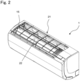
- Fig. 2 is a perspective view of the indoor unit 1 as viewed obliquely from above.
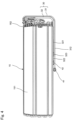
- Fig. 3 is a front view of the indoor unit 1.
- the indoor unit 1 includes a casing 21, and the indoor heat exchanger 15, the indoor fan 18, and the like are accommodated in the casing 21.
- An upper portion of the casing 21 is provided with an intake port 22 through which indoor air is taken in.
- indoor air enters the casing 21 through the intake port 22 and flows toward the indoor fan 18.
- a filter (not illustrated) is attached to the intake port 22.
- a lower portion of the casing 21 is provided with a blow-out port 23 through which air from the indoor fan 18 (indoor air subjected to heat exchange with the indoor heat exchanger 15) blows out.
- a horizontal flap 24 is rotatably attached to a peripheral edge portion of the blow-out port 23.
- the horizontal flap 24 changes its position from a stop position to close the blow-out port 23 to an operation position to open the blow-out port 23 to adjust a vertical airflow direction of air blown out from the blow-out port 23.
- Fig. 4 is a front view of the indoor heat exchanger 15 and a peripheral portion of the indoor heat exchanger 15.
- the indoor heat exchanger 15 includes a heat exchange portion 151 and a plurality of heat transfer tubes 152 extending through the heat exchange portion 151 in a left-right direction.
- the heat exchange portion 151 and the heat transfer tubes 152 are each formed of aluminum or an aluminum alloy.
- the indoor unit 1 further includes a connection pipe 30 that is fluidly connected to the heat transfer tubes 152 of the indoor heat exchanger 15 and through which the refrigerant flows.
- the connection pipe 30 includes a liquid-refrigerant connection pipe 31 constituting a part of the connection pipe L1 and a gas-refrigerant connection pipe 32 constituting a part of the connection pipe L2.
- the liquid-refrigerant connection pipe 31 guides a liquid refrigerant from the electric expansion valve 14 to the indoor heat exchanger 15 during the cooling operation and the dehumidifying operation.
- the gas-refrigerant connection pipe 32 guides a gas refrigerant from the indoor heat exchanger 15 to the compressor 11 during the cooling operation and the dehumidifying operation.
- the liquid-refrigerant connection pipe 31 and the gas-refrigerant connection pipe 32 are each an example of the connection pipe.
- the liquid-refrigerant connection pipe 31 has includes a first liquid-refrigerant pipe 311 (illustrated in Fig. 5 ) formed of aluminum or an aluminum alloy, and a second liquid-refrigerant pipe 312 formed of copper or a copper alloy.
- the first liquid-refrigerant pipe 311 has one end fluidly connected to the heat transfer tubes 152 of the indoor heat exchanger 15.
- the first liquid-refrigerant pipe 311 is an example of a first refrigerant pipe.
- the aluminum and the aluminum alloy are each an example of a first metal.
- the second liquid-refrigerant pipe 312 is an example of a second refrigerant pipe.
- the copper and the copper alloy are each an example of a second metal.
- the second liquid-refrigerant pipe 312 has one end fluidly connected to the other end of the first liquid-refrigerant pipe 311 through a third liquid-refrigerant pipe 313 (illustrated in Fig. 5 ) formed of stainless steel.
- the second liquid-refrigerant pipe 312 has the other end fixed to a liquid-refrigerant flare union 41 by brazing.
- the third liquid-refrigerant pipe 313 has a lower end fixed to an end of the second liquid-refrigerant pipe 312 adjacent to the third liquid-refrigerant pipe 313 by brazing, i.e., fixed to the one end of the second liquid-refrigerant pipe 312 by brazing.
- the third liquid-refrigerant pipe 313 has an upper end fixed to an end of the first liquid-refrigerant pipe 311 adjacent to the third liquid-refrigerant pipe 313 by brazing, i.e., fixed to the other end of the first liquid-refrigerant pipe 311 by brazing.
- the upper end of the third liquid-refrigerant pipe 313 corresponds to an end of the third liquid-refrigerant pipe 313 adjacent to the second liquid-refrigerant pipe 312, i.e., a second-liquid-refrigerant-pipe 312-side end of the third liquid-refrigerant pipe 313.
- the lower end of the third liquid-refrigerant pipe 313 corresponds to an end of the third liquid-refrigerant pipe 313 adjacent to the first liquid-refrigerant pipe 311, i.e., a first-liquid-refrigerant-pipe 311-side end of the third liquid-refrigerant pipe 313.
- the gas-refrigerant connection pipe 32 is similar in configuration to the liquid-refrigerant connection pipe 31, and includes a first gas-refrigerant pipe 321 formed of aluminum or an aluminum alloy, and a second gas-refrigerant pipe 322 formed of copper or a copper alloy.
- the first gas-refrigerant pipe 321 has one end fluidly connected to the heat transfer tubes 152 of the indoor heat exchanger 15.
- the second gas-refrigerant pipe 322 has one end fluidly connected to the other end of the first gas-refrigerant pipe 321 through a third gas-refrigerant pipe 323 formed of stainless steel.
- the second gas-refrigerant pipe 322 has the other end fixed to a gas-refrigerant flare union 42 by brazing.
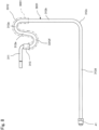
- Fig. 5 is a front view of the liquid-refrigerant connection pipe 31 and a peripheral portion of the liquid-refrigerant connection pipe 31.
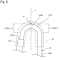
- Fig. 6 is an enlarged view of a main portion of the second liquid-refrigerant pipe 312 of the liquid-refrigerant connection pipe 31.
- the second liquid-refrigerant pipe 312 of the liquid-refrigerant connection pipe 31 includes a first section 312a and a second section 312b disposed below and integrally formed with the first section 312a, i.e., seamlessly formed with the first section 312a.
- the second liquid-refrigerant pipe 312 further includes a third section 312c and a fourth section 312d provided adjacent to the liquid-refrigerant flare union 41 relative to the second section 312b.
- the second liquid-refrigerant pipe 312 further includes a fifth section 312e provided adjacent to the third liquid-refrigerant pipe 313 relative to the first section 312a.
- the second liquid-refrigerant pipe 312 has an outer peripheral surface extending from a lower end of the fifth section 312e to an upper end of the second section 312b, the outer peripheral surface entirely being covered with a waterproof tube 51.
- the waterproof tube 51 is an example of a covering member.
- the lower end of the fifth section 312e corresponds to an end of the fifth section 312e adjacent to the first liquid-refrigerant pipe 311, i.e., the one end of the second liquid-refrigerant pipe 312.
- the upper end of the second section 312b corresponds to an end of the second section 312b adjacent to the first liquid-refrigerant pipe 311, i.e., a first-liquid-refrigerant-pipe 311-side end of the second section 312b.
- the first section 312a forms a section of the second liquid-refrigerant pipe 312 that is bent to protrude upward. That is, the second liquid-refrigerant pipe 312 is formed so as to be folded back at first section 312a.
- the first section 312a constitutes a bent pipe portion so as to extend upward from the upper end of the second section 312b, make a U-turn, and then extends downward.
- the first section 312a includes a first curved section 312a-1 and a second curved section 312a-2 provided on a right side of the first curved section 312a-1, i.e., on a side opposite to a first-liquid-refrigerant-pipe 311-side relative to the first curved section 312a-1.
- a vertical line L passing through an apex P of the first section 312a corresponds to a boundary line between the first curved section 312a-1 and the second curved section 312a-2.
- the first curved section 312a-1 is disposed adjacent to the first liquid-refrigerant pipe 311 relative to the apex P of the first section 312a.
- the first curved section 312a-1 is disposed on the first-liquid-refrigerant-pipe 311-side relative to the apex P of the first section 312a.
- the first curved section 312a-1 can be said to be a portion of the first section 312a, the portion being adjacent to the first liquid-refrigerant pipe 311 relative to the vertical line L.
- the portion adjacent to the first liquid-refrigerant pipe 311 corresponds to an upstream portion in a direction of the flow of the refrigerant when the refrigerant flows from the first liquid-refrigerant pipe 311 to the second liquid-refrigerant pipe 312, and corresponds to a downstream portion in a direction of the flow of the refrigerant when the refrigerant flows from the second liquid-refrigerant pipe 312 to the first liquid-refrigerant pipe 311.
- the second curved section 312a-2 is disposed remote from the first liquid-refrigerant pipe 311 relative to the apex P of the first section 312a.
- the second curved section 312a-2 is disposed on the side opposite to the first-liquid-refrigerant-pipe 311-side relative to the apex P of the first section 312a.
- the second curved section 312a-2 can be said to be a portion of the first section 312a, the portion being adjacent to the liquid-refrigerant flare union 41 (remote from the first liquid-refrigerant pipe 311) relative to the vertical line L.
- the portion remote from the first liquid-refrigerant pipe 311 corresponds to a downstream portion in a direction of the flow of the refrigerant when the refrigerant flows from the first liquid-refrigerant pipe 311 to the second liquid-refrigerant pipe 312, and corresponds to an upstream portion in a direction of the flow of the refrigerant when the refrigerant flows from the second liquid-refrigerant pipe 312 to the first liquid-refrigerant pipe 311.
- the second section 312b is formed integrally with the first section 312a, i.e., seamlessly with the first section 312a and is continuous with a lower end of the second curved section 312a-2 of the first section 312a.
- the second section constitutes a straight pipe portion extending along an approximate vertical direction.
- the lower end of the second curved section 312a-2 corresponds to an end of the first section 312a, the end being remote from the first liquid-refrigerant pipe 311.
- the approximate vertical direction refers to a vertical direction or refers to a direction inclined at an angle of, for example, 20 degrees or less relative to the vertical direction.
- the third section 312c is formed integrally with the second section 312b, i.e., seamlessly with the second section 312b and is continuous with a lower end of the second section 312b.
- the third section 312c constitutes a bent pipe portion that extends from the lower end of the second section 312b and then extends toward the liquid-refrigerant flare union 41.
- the lower end of the second section 312b corresponds to an end of the second section 312b remote from the first liquid-refrigerant pipe 311 (adjacent to the liquid-refrigerant flare union 41).
- the fourth section 312d is formed integrally with the third section 312c and is continuous with a left end of the third section 312c.
- the fourth section 312d constitutes a straight pipe portion extending along an approximate horizontal direction.
- the left end of the third section 312c corresponds to an end of the second liquid-refrigerant pipe 312, the end being remote from the first liquid-refrigerant pipe 311 (adjacent to the liquid-refrigerant flare union 41).
- the approximate horizontal direction refers to a horizontal direction or a direction inclined at an angle of, for example, 20 degrees or less relative to the horizontal direction.
- the fifth section 312e is formed integrally with the first section 312a, i.e., seamlessly with the first section 312a and is continuous with a lower end of the first curved section 312a-1 of the first section 312a.
- the fifth section 312e constitutes a straight pipe portion extending along a direction inclined relative to the vertical direction.
- the lower end of the fifth section 312e is fixed to the upper end of the third liquid-refrigerant pipe 313 by brazing.
- the lower end of the first curved section 312a-1 corresponds to an end of the first curved section 312a-1 adjacent to the first liquid-refrigerant pipe 311.
- the lower end of the fifth section 312e corresponds to an end of the fifth section 312e, the end being adjacent to the first liquid-refrigerant pipe 311 and further corresponds to an end of the second liquid-refrigerant pipe 312, the end being adjacent to the first liquid-refrigerant pipe 311.
- the waterproof tube 51 is formed of a tube made of a waterproof material (for example, vinyl chloride, silicone rubber, fluorine-based polymer, or the like) and shrunk by heating. Accordingly, the waterproof tube 51 is in intimate contact with an outer peripheral surface of the second liquid-refrigerant pipe 312.
- a waterproof material for example, vinyl chloride, silicone rubber, fluorine-based polymer, or the like
- the waterproof tube 51 is in intimate contact with not only an outer peripheral surface of the first section 312a and an outer peripheral surface of the upper end of the second section 312b but also an outer peripheral surface of the upper end of the third liquid-refrigerant pipe 313 to cover the entire circumference of the upper end.
- the outer peripheral surface of the first section 312a of the second liquid-refrigerant pipe 312 is entirely covered with the waterproof tube 51. This makes it possible to prevent, for example, dew condensation water from flowing from the first section 312a of the second liquid-refrigerant pipe 312 toward the first liquid-refrigerant pipe 311.
- the waterproof tube 51 can reduce the possibility that dew condensation water adheres to the first liquid-refrigerant pipe 311. It is therefore possible to prevent the first liquid-refrigerant pipe 311 from suffering electrolytic corrosion.
- the waterproof tube 51 is in intimate contact with the outer peripheral surface of the first section 312a of the second liquid-refrigerant pipe 312, it is possible to reduce the possibility that liquid such as dew condensation water enters a space between the waterproof tube 51 and the first section 312a of the second liquid-refrigerant pipe 312. It is therefore possible to prevent liquid containing copper ions from being generated in the first section 312a of the second liquid-refrigerant pipe 312.
- the waterproof tube 51 further covers the upper end of the third liquid-refrigerant pipe 313, a lower end surface of the first section 312a of the second liquid-refrigerant pipe 312, i.e., a boundary surface between the second liquid-refrigerant pipe 312 and the third liquid-refrigerant pipe 313 is not exposed. It is therefore possible to prevent liquid containing copper ions from being generated in the first section 312a of the second liquid-refrigerant pipe 312. As a result, it is also possible to reduce the possibility that the first liquid-refrigerant pipe 311 suffers electrolytic corrosion.
- the waterproof tube 51 further covers the second curved section 312a-2 together with the first curved section 312a-1. This makes it possible to prevent liquid containing copper ions from being generated in the second curved section 312a-2. It is therefore also possible to reduce the possibility that the first liquid-refrigerant pipe 311 suffers electrolytic corrosion.
- one indoor unit 1 is connected to one outdoor unit 2, or alternatively, a plurality of indoor units 1 may be connected.
- the above-described air conditioner is of a pair-type, or alternatively, the air conditioner may be of a multi-type.
- the indoor unit 1 is an example of the heat exchange unit in the first embodiment, or alternatively, the outdoor unit 2 may be an example of the heat exchange unit.
- the connection pipe fluidly connected to the outdoor heat exchanger 13 may be configured as the first liquid-refrigerant pipe 311 and the second liquid-refrigerant pipe 312.
- the connection pipe corresponds to a refrigerant pipe between the four-way switching valve 12 and the outdoor heat exchanger 13 or a refrigerant pipe between the outdoor heat exchanger 13 and the electric expansion valve 14.
- the first liquid-refrigerant pipe 311 is formed of aluminum or an aluminum alloy in the first embodiment, or alternatively, may be formed of metal other than aluminum or an aluminum alloy. Also in this case, the metal of which the first liquid-refrigerant pipe 311 is formed is selected so as to be lower in potential than the metal of which the second liquid-refrigerant pipe 312 is formed.
- the second liquid-refrigerant pipe 312 is formed of copper or a copper alloy in the first embodiment, or alternatively, may be formed of metal other than copper or a copper alloy. Also in this case, the metal of which the second liquid-refrigerant pipe 312 is formed is selected so as to be higher in potential than the metal of which the first liquid-refrigerant pipe 311 is formed.
- the fifth section 312e of the second liquid-refrigerant pipe 312 extends in a direction inclined relative to the vertical direction in the first embodiment, or alternatively, may extend in the vertical direction.
- the second liquid-refrigerant pipe 312 includes the fifth section 312e in the first embodiment, or alternatively, need not include the fifth section 312e.
- the first gas-refrigerant pipe 321 is formed of aluminum or an aluminum alloy in the first embodiment, or alternatively, may be formed of metal other than aluminum or an aluminum alloy. Also in this case, the metal of which the first gas-refrigerant pipe 321 is formed is selected so as to be lower in potential than the metal of which the second gas-refrigerant pipe 322 is formed.
- the second gas-refrigerant pipe 322 is formed of copper or a copper alloy in the first embodiment, or alternatively, may be formed of metal other than copper or a copper alloy. Also in this case, the metal of which the second gas-refrigerant pipe 322 is formed is selected so as to be higher in potential than the metal of which the first gas-refrigerant pipe 321 is formed.
- the position where the second gas-refrigerant pipe 322 has one end connected to the other end of the first gas-refrigerant pipe 321 through the third gas-refrigerant pipe 323 and the position where the second liquid-refrigerant pipe 312 has one end connected to the other end of the first liquid-refrigerant pipe 311 through the third liquid-refrigerant pipe 313 are set different from each other in the first embodiment, or alternatively, may be set identical to each other.
- the first gas-refrigerant pipe 321 and the second gas-refrigerant pipe 322 may be similar in shape to the first liquid-refrigerant pipe 311 and the second liquid-refrigerant pipe 312.
- the end of the second gas-refrigerant pipe adjacent to the first gas-refrigerant pipe and the first curved section of the second gas-refrigerant pipe may be covered with a covering member or a coating film that prevents adhesion of liquid.
- No flow divider is interposed between the heat transfer tubes 152 of the indoor heat exchanger 15 and one end of the first liquid-refrigerant pipe 311 in the first embodiment, or alternatively, a flow divider may be interposed.
- the flow divider may divide one refrigerant flow into two refrigerant flows, or may divide one refrigerant flow into three or more refrigerant flows.
- the third liquid-refrigerant pipe 313 is interposed between the other end of the first liquid-refrigerant pipe 311 and one end of the second liquid-refrigerant pipe 312 in the first embodiment, or alternatively, the third liquid-refrigerant pipe 313 need not be interposed.
- the second liquid-refrigerant pipe 312 may have one end directly connected to the other end of the first liquid-refrigerant pipe 311.
- the waterproof tube 51 covers the outer peripheral surface of the first curved section 312a-1 and the outer peripheral surface of the second curved section 312a-2 in the first embodiment, or alternatively, may cover only the outer peripheral surface of the first curved section 312a-1 and need not cover the outer peripheral surface of the second curved section 312a-2.
- the waterproof tube 51 covers the outer peripheral surface of the upper end of the third liquid-refrigerant pipe 313 in the first embodiment, or alternatively, need not cover the outer peripheral surface of the upper end of the third liquid-refrigerant pipe 313.
- the outer peripheral surface extending from the end of the second liquid-refrigerant pipe 312 adjacent to the first liquid-refrigerant pipe 311 to the end of the first curved section 312a-1 adjacent to the second curved section 312a-2 needs to be covered with the waterproof tube 51.
- the waterproof tube 51 is formed so as not to cover the outer peripheral surface of the lower end of the third liquid-refrigerant pipe 313 in the first embodiment, or alternatively, may be formed so as to cover the outer peripheral surface of the lower end of the third liquid-refrigerant pipe 313. In other words, for example, the waterproof tube 51 may be formed so as to cover the entire outer peripheral surface of the third liquid-refrigerant pipe 313.
- the outer peripheral surface of the first curved section 312a-1 of the first section 312a and the outer peripheral surface of the fifth section 312e are covered with the waterproof tube 51 in the first embodiment, or alternatively, the outer peripheral surface of the first curved section 312a-1 of the first section 312a and the outer peripheral surface of the fifth section 312e may be covered with a coating film.
- the coating film is made of a waterproof material (for example, fluororesin, fiber reinforced plastic (FRP), acrylic rubber, or the like).
- FRP fiber reinforced plastic
- acrylic rubber acrylic rubber
- the coating film may be formed so as not to cover the outer peripheral surface of the second curved section 312a-2 of the first section 312a, or may be formed so as to cover the outer peripheral surface of the second curved section 312a-2 of the first section 312a.
- Fig. 7 is a front view of a liquid-refrigerant connection pipe 31 of an air conditioner of a second embodiment of the present disclosure.
- the air conditioner of the second embodiment is similar in configuration to the air conditioner of the first embodiment except that a waterproof tube 2051 is provided.
- the waterproof tube 2051 is an example of the covering member.
- the waterproof tube 2051 is different from the waterproof tube 51 of the first embodiment only in shape. More specifically, the waterproof tube 2051 is formed longer than the waterproof tube 51 of the first embodiment, and is also in intimate contact with an outer peripheral surface of a right end of the first liquid-refrigerant pipe 311 to cover the entire circumference of the right end.
- the right end of the first liquid-refrigerant pipe 311 corresponds to an end of the first liquid-refrigerant pipe 311 adjacent to the second liquid-refrigerant pipe 312, i.e., a second-liquid-refrigerant-pipe 312-side end of the first liquid-refrigerant pipe 311.
- the waterproof tube 2051 further covers the outer peripheral surface of the right end of the first liquid-refrigerant pipe 311, so that it is possible to prevent liquid from adhering to the right end of the first liquid-refrigerant pipe 311. It is therefore possible to reduce the possibility that the first liquid-refrigerant pipe 311 suffers electrolytic corrosion.
- the third liquid-refrigerant pipe 313 is interposed between the first liquid-refrigerant pipe 311 and the second liquid-refrigerant pipe 312 in the second embodiment, or alternatively, the third liquid-refrigerant pipe 313 need not be interposed.
- the second liquid-refrigerant pipe 312 may be directly fluidly connected to the first liquid-refrigerant pipe 311.
- the waterproof tube 2051 may cover the entire outer peripheral surface of the right end of the first liquid-refrigerant pipe 311.
- Fig. 8 is a front view of a liquid-refrigerant connection pipe 3031 of an air conditioner of a third embodiment of the present disclosure.
- the air conditioner of the third embodiment is similar in configuration to the air conditioner of the first embodiment except that the liquid-refrigerant connection pipe 3031 and a waterproof tube 3051 are provided.
- the liquid-refrigerant connection pipe 3031 is an example of the connection pipe.
- the waterproof tube 3051 is an example of the covering member.
- the liquid-refrigerant connection pipe 3031 includes a first liquid-refrigerant pipe 3311 formed of aluminum or an aluminum alloy, a second liquid-refrigerant pipe 3312 formed of copper or a copper alloy, and a third liquid-refrigerant pipe 3313 formed of stainless steel.
- first liquid-refrigerant pipe 3311, the second liquid-refrigerant pipe 3312, and the third liquid-refrigerant pipe 3313 are different from the first liquid-refrigerant pipe 311, the second liquid-refrigerant pipe 312, and the third liquid-refrigerant pipe 313 of the first embodiment only in shape, respectively.
- the first liquid-refrigerant pipe 3311 is disposed below the apex of the first section 312a of the second liquid-refrigerant pipe 3312 and above the third liquid-refrigerant pipe 3313.
- the second liquid-refrigerant pipe 3312 is identical in configuration to the second liquid-refrigerant pipe 312 of the first embodiment, and further includes a bent section 3312f
- the bent section 3312f is formed integrally with the other sections such as the first section 312a and the like, i.e., seamlessly with the other sections such as the first section 312a and the like.
- the bent section 3312f is bent to protrude downward.
- the bent section 3312f has a shape obtained by turning the first section 312a upside down.
- a right end of the bent section 3312f is continuous with the lower end of the fifth section 312e.
- a left end of the bent section 3312f is fixed to a lower end of the third liquid-refrigerant pipe 3313 by brazing.
- the right end of the bent section 3312f corresponds to an end of the bent section 3312f remote from the first liquid-refrigerant pipe 3311, i.e., an end of the bent section 3312f, the end being disposed on a side opposite to a first-liquid-refrigerant-pipe 3311-side.
- the left end of the bent section 3312f corresponds to an end of the bent section 3312f adjacent to the first liquid-refrigerant pipe 3311, i.e., a first-liquid-refrigerant-pipe 3311-side end of the bent section 3312f.
- the left end of the bent section 3312f further corresponds to an end of the second liquid-refrigerant pipe 3312 adjacent to the first liquid-refrigerant pipe 3311, i.e., a first-liquid-refrigerant-pipe 3311-side end of the second liquid-refrigerant pipe 3312.
- a lower end of the third liquid-refrigerant pipe 3313 corresponds to an end of the third liquid-refrigerant pipe 3313 adjacent to the second liquid-refrigerant pipe 3312, i.e., a second-liquid-refrigerant-pipe 3312-side end of the third liquid-refrigerant pipe 3313.
- the third liquid-refrigerant pipe 3313 is disposed between the first liquid-refrigerant pipe 3311 and the second liquid-refrigerant pipe 3312.
- An upper end of the third liquid-refrigerant pipe 3313 is fixed to a right end of the first liquid-refrigerant pipe 3311 by brazing.
- the upper end of the third liquid-refrigerant pipe 3313 corresponds to an end of the third liquid-refrigerant pipe 3313 adjacent to the first liquid-refrigerant pipe 3311, i.e., a first-liquid-refrigerant-pipe 3311-side end of third liquid-refrigerant pipe 3313.
- the right end of the first liquid-refrigerant pipe 3311 corresponds to an end of the first liquid-refrigerant pipe 3311 adjacent to the second liquid-refrigerant pipe 3312, i.e., a second-liquid-refrigerant-pipe 3312-side end of the first liquid-refrigerant pipe 3311.
- the waterproof tube 3051 is different from the waterproof tube 51 of the first embodiment only in shape. More specifically, the waterproof tube 3051 is formed longer than the waterproof tube 51 of the first embodiment, and further covers the entire outer peripheral surface of the bent section 3312f.
- the second liquid-refrigerant pipe 3312 is provided with the bent section 3312f closer to the first liquid-refrigerant pipe 3311 than the first section 312a, the bent section 3312f being bent to protrude downward. This allows the bent section 3312f to stop, even when dew condensation water, for example, flows along the second liquid-refrigerant pipe 3312 from the first section 312a toward the first liquid-refrigerant pipe 311, the flow of dew condensation water. It is therefore possible to reduce the possibility that the first liquid-refrigerant pipe 3311 suffers electrolytic corrosion.
- the third liquid-refrigerant pipe 3313 is interposed between the first liquid-refrigerant pipe 3311 and the second liquid-refrigerant pipe 3312 in the third embodiment, or alternatively, the third liquid-refrigerant pipe 3313 need not be interposed.
- the second liquid-refrigerant pipe 3312 may be directly fluidly connected to the first liquid-refrigerant pipe 3311.
- the outer peripheral surface extending from the left end of the bent section 3312f to the end of the first curved section 312a-1 adjacent to the second curved section 312a-2 (the second-curved-section 312a-2-side end of the first curved section 312a-1) may be covered with the waterproof tube 3051.
- the present disclosure is not limited to the first to third embodiments and modifications of the first to third embodiments, and various modifications and variations may be made within the scope of the present disclosure.
- some of the contents described in the first to third embodiments may be deleted or replaced to obtain one embodiment of the present disclosure.
- the second and third embodiments may be modified as in the modification of the first embodiment.
- the configurations of the second and third embodiments may be applied to the outdoor unit 2.
Landscapes
- Engineering & Computer Science (AREA)
- Mechanical Engineering (AREA)
- General Engineering & Computer Science (AREA)
- Physics & Mathematics (AREA)
- Thermal Sciences (AREA)
- Chemical & Material Sciences (AREA)
- Combustion & Propulsion (AREA)
- Air Filters, Heat-Exchange Apparatuses, And Housings Of Air-Conditioning Units (AREA)
Abstract
Description
- The present disclosure relates to a heat exchange unit and an air conditioner.
- Examples of a known heat exchange unit include an indoor unit constituting a part of an air conditioner (see, for example,
JP 2013-155892 A - The connection pipe includes a bent section formed to protrude upward. The connection pipe further includes a first refrigerant pipe disposed adjacent to the heat exchanger and a second refrigerant pipe disposed remote from the heat exchanger. The first refrigerant pipe is formed of aluminum or an aluminum alloy, while the second refrigerant pipe is formed of copper or a copper alloy.
- Patent Literature 1:
JP 2013-155892 A - When a connection point between the first refrigerant pipe and the second refrigerant pipe is disposed adjacent to the heat exchanger relative to an apex of the bent section, an end of the second refrigerant pipe adjacent to the first refrigerant pipe is disposed above an end of the first refrigerant pipe adjacent to the second refrigerant pipe. In such a state, when dew condensation occurs at the end of the second refrigerant pipe adjacent to the first refrigerant pipe, dew condensation water containing copper ions flows from the second refrigerant pipe to the first refrigerant pipe formed of aluminum or aluminum alloy.
- The known heat exchange unit therefore has a problem that electrolytic corrosion may develop in the first refrigerant pipe in a manner that depends on a position setting of the connection point between the first refrigerant pipe and the second refrigerant pipe.
- It is therefore an object of the present disclosure to provide a heat exchange unit and an air conditioner capable of preventing a first refrigerant pipe from suffering electrolytic corrosion.
- A heat exchange unit of the present disclosure includes:
- a heat exchanger; and
- a connection pipe that is connected to the heat exchanger and through which a refrigerant flows, in which
- the connection pipe includes:
- a first refrigerant pipe having one end connected to the heat exchanger and formed of a first metal; and
- a second refrigerant pipe formed of a second metal having a smaller ionization tendency than an ionization tendency of the first metal of the first refrigerant pipe, second refrigerant pipe having one end connected to an other end of the first refrigerant pipe,
- the second refrigerant pipe includes:
- a first section that is bent to protrude upward, the first section having an end of the first section remote from the first refrigerant pipe;
- a second section that is continuous with the end of the first section and extends along an approximate vertical direction,
- the first section includes:
- a first curved section disposed adjacent to the first refrigerant pipe relative to an apex of the first section; and
- a second curved section disposed remote from the first refrigerant pipe relative to the apex of the first section, and
- a covering member or a coating film is provided in intimate contact with the second refrigerant pipe to cover the one end of the second refrigerant pipe adjacent to the first refrigerant pipe and the first curved section.
- The approximate vertical direction means a vertical direction or a direction inclined at an angle of, for example, 20 degrees or less relative to the vertical direction.
- With the above-described configuration, the covering member or the coating film covers the one end of the second refrigerant pipe adjacent to the first refrigerant pipe and the first curved section, so that it is possible to prevent the first refrigerant pipe from suffering electrolytic corrosion.
- In the heat exchange unit according to one aspect of the present disclosure, the first refrigerant pipe has the other end adjacent to the second refrigerant pipe covered with the covering member or the coating film.
- According to the aspect, the covering member or the coating film covers the other end of the second refrigerant pipe adjacent to the first refrigerant pipe, so that it is possible to reduce the possibility that the first refrigerant pipe suffers electrolytic corrosion.
- In the heat exchange unit according to one aspect of the present disclosure, the second refrigerant pipe has the one end connected to the other end of the first refrigerant pipe through a third refrigerant pipe formed of stainless steel, and the third refrigerant pipe is covered with the covering member or the coating film.
- According to the aspect, even when the third refrigerant pipe is disposed between the other end of the first refrigerant pipe and the one end of the second refrigerant pipe, the covering member or the coating film covers the third refrigerant pipe, so that it is possible to reduce the possibility that the first refrigerant pipe suffers electrolytic corrosion.
- In the heat exchange unit according to one aspect of the present disclosure, the second curved section of the second refrigerant pipe is covered with the covering member or the coating film.
- According to the aspect, the covering member or the coating film covers the second curved section of the second refrigerant pipe, so that it is possible to reduce the possibility that the first refrigerant pipe suffers electrolytic corrosion.
- In the heat exchange unit according to one aspect of the present disclosure, the second refrigerant pipe includes a bent section that is bent to protrude downward.
- According to the aspect, when the bent section is provided adjacent to the first refrigerant pipe relative to the first section, it is possible to reduce the possibility that the first refrigerant pipe suffers electrolytic corrosion.
- The heat exchange unit according to one aspect of the present disclosure is an indoor unit.
- According to the aspect, the heat exchange unit is an indoor unit, so that it is possible to prevent the first refrigerant pipe of the connection pipe of the indoor unit from suffering electrolytic corrosion.
- An air conditioner according to one aspect of the present disclosure includes any one of the above-described heat exchange units.
- With the above-described configuration, the heat exchange unit is provided, so that it is possible to prevent the first refrigerant pipe from suffering electrolytic corrosion.
-
-
Fig. 1 is a refrigerant circuit diagram of an air conditioner of a first embodiment of the present disclosure. -
Fig. 2 is a perspective view of an indoor unit of the air conditioner of the first embodiment. -
Fig. 3 is a front view of the indoor unit of the air conditioner of the first embodiment. -
Fig. 4 is a front view of an indoor heat exchanger of the first embodiment and a peripheral portion of the indoor heat exchanger. -
Fig. 5 is a front view of a liquid-refrigerant connection pipe of the first embodiment. -
Fig. 6 is an enlarged view of a main portion of a second liquid-refrigerant pipe of the first embodiment. -
Fig. 7 is a front view of a liquid-refrigerant connection pipe of a second embodiment of the present disclosure. -
Fig. 8 is a front view of a liquid-refrigerant connection pipe of a third embodiment of the present disclosure. - A heat exchange unit and an air conditioner of the present disclosure will be described in detail below with reference to embodiments illustrated in the drawings. Note that the same parts in the drawings are denoted by the same reference numerals to avoid the description from being redundant. Upper, lower, left, and right in the description correspond to upper, lower, left, and right in a state where an indoor unit is installed in a room.
-
Fig. 1 is a diagram illustrating a refrigerant circuit RC provided in an air conditioner of a first embodiment of the present disclosure. This air conditioner is of a type in which anoutdoor unit 2 is paired one-to-one with anindoor unit 1. Theindoor unit 1 is an example of the heat exchange unit. - The air conditioner includes the
indoor unit 1 and theoutdoor unit 2 connected to theindoor unit 1 via the refrigerant circuit RC. - The refrigerant circuit RC includes a
compressor 11, a four-way switching valve 12, anoutdoor heat exchanger 13, anelectric expansion valve 14, anindoor heat exchanger 15 as an example of a heat exchanger, and anaccumulator 16. As thecompressor 11 is driven, a refrigerant (for example, an HFC refrigerant such as R410A or R32) circulates in the refrigerant circuit RC. - More specifically, the four-
way switching valve 12 has one end connected to a discharge side of thecompressor 11. The four-way switching valve 12 has the other end connected to one end of theoutdoor heat exchanger 13. Theoutdoor heat exchanger 13 has the other end connected to one end of theelectric expansion valve 14. Theelectric expansion valve 14 has the other end connected to one end of theindoor heat exchanger 15 via a shutoff valve V1 and a connection pipe L1. Theindoor heat exchanger 15 has the other end connected to one end of theaccumulator 16 via a connection pipe L2, a shutoff valve V2, and the four-way switching valve 12. Theaccumulator 16 has the other end connected to an intake-side portion of thecompressor 11. - The
indoor unit 1 is equipped with theindoor heat exchanger 15 and anindoor fan 18. Theindoor fan 18 is, for example, a cross-flow fan, and takes in indoor air through theindoor heat exchanger 15. - The
outdoor unit 2 is equipped with thecompressor 11, the four-way switching valve 12, theoutdoor heat exchanger 13, theelectric expansion valve 14, theaccumulator 16, and anoutdoor fan 17. - The air conditioner switches the four-
way switching valve 12 to a switching position indicated by a solid line to activate thecompressor 11 for cooling operation and dehumidifying operation, and switches the four-way switching valve 12 to a switching position indicated by a dotted line to activate thecompressor 11 for heating operation. A direction of a solid arrow inFig. 1 indicates a direction in which the refrigerant flows during the cooling operation and the dehumidifying operation. A direction indicated by a dotted arrow inFig. 1 indicates a direction in which the refrigerant flows during the heating operation. -
Fig. 2 is a perspective view of theindoor unit 1 as viewed obliquely from above.Fig. 3 is a front view of theindoor unit 1. - As illustrated in
Figs. 2 and3 , theindoor unit 1 includes acasing 21, and theindoor heat exchanger 15, theindoor fan 18, and the like are accommodated in thecasing 21. - An upper portion of the
casing 21 is provided with anintake port 22 through which indoor air is taken in. When theindoor fan 18 is driven, indoor air enters thecasing 21 through theintake port 22 and flows toward theindoor fan 18. At this time, in order to prevent dust and the like from entering thecasing 21 together with indoor air, a filter (not illustrated) is attached to theintake port 22. - A lower portion of the
casing 21 is provided with a blow-outport 23 through which air from the indoor fan 18 (indoor air subjected to heat exchange with the indoor heat exchanger 15) blows out. Ahorizontal flap 24 is rotatably attached to a peripheral edge portion of the blow-outport 23. - When the cooling operation or the like is started, the
horizontal flap 24 changes its position from a stop position to close the blow-outport 23 to an operation position to open the blow-outport 23 to adjust a vertical airflow direction of air blown out from the blow-outport 23. -
Fig. 4 is a front view of theindoor heat exchanger 15 and a peripheral portion of theindoor heat exchanger 15. - The
indoor heat exchanger 15 includes aheat exchange portion 151 and a plurality ofheat transfer tubes 152 extending through theheat exchange portion 151 in a left-right direction. Theheat exchange portion 151 and theheat transfer tubes 152 are each formed of aluminum or an aluminum alloy. - The
indoor unit 1 further includes aconnection pipe 30 that is fluidly connected to theheat transfer tubes 152 of theindoor heat exchanger 15 and through which the refrigerant flows. - The
connection pipe 30 includes a liquid-refrigerant connection pipe 31 constituting a part of the connection pipe L1 and a gas-refrigerant connection pipe 32 constituting a part of the connection pipe L2. The liquid-refrigerant connection pipe 31 guides a liquid refrigerant from theelectric expansion valve 14 to theindoor heat exchanger 15 during the cooling operation and the dehumidifying operation. On the other hand, the gas-refrigerant connection pipe 32 guides a gas refrigerant from theindoor heat exchanger 15 to thecompressor 11 during the cooling operation and the dehumidifying operation. The liquid-refrigerant connection pipe 31 and the gas-refrigerant connection pipe 32 are each an example of the connection pipe. - The liquid-
refrigerant connection pipe 31 has includes a first liquid-refrigerant pipe 311 (illustrated inFig. 5 ) formed of aluminum or an aluminum alloy, and a second liquid-refrigerant pipe 312 formed of copper or a copper alloy. The first liquid-refrigerant pipe 311 has one end fluidly connected to theheat transfer tubes 152 of theindoor heat exchanger 15. The first liquid-refrigerant pipe 311 is an example of a first refrigerant pipe. The aluminum and the aluminum alloy are each an example of a first metal. The second liquid-refrigerant pipe 312 is an example of a second refrigerant pipe. The copper and the copper alloy are each an example of a second metal. - The second liquid-
refrigerant pipe 312 has one end fluidly connected to the other end of the first liquid-refrigerant pipe 311 through a third liquid-refrigerant pipe 313 (illustrated inFig. 5 ) formed of stainless steel. On the other hand, the second liquid-refrigerant pipe 312 has the other end fixed to a liquid-refrigerant flare union 41 by brazing. - The third liquid-
refrigerant pipe 313 has a lower end fixed to an end of the second liquid-refrigerant pipe 312 adjacent to the third liquid-refrigerant pipe 313 by brazing, i.e., fixed to the one end of the second liquid-refrigerant pipe 312 by brazing. On the other hand, the third liquid-refrigerant pipe 313 has an upper end fixed to an end of the first liquid-refrigerant pipe 311 adjacent to the third liquid-refrigerant pipe 313 by brazing, i.e., fixed to the other end of the first liquid-refrigerant pipe 311 by brazing. The upper end of the third liquid-refrigerant pipe 313 corresponds to an end of the third liquid-refrigerant pipe 313 adjacent to the second liquid-refrigerant pipe 312, i.e., a second-liquid-refrigerant-pipe 312-side end of the third liquid-refrigerant pipe 313. The lower end of the third liquid-refrigerant pipe 313 corresponds to an end of the third liquid-refrigerant pipe 313 adjacent to the first liquid-refrigerant pipe 311, i.e., a first-liquid-refrigerant-pipe 311-side end of the third liquid-refrigerant pipe 313. - The gas-
refrigerant connection pipe 32 is similar in configuration to the liquid-refrigerant connection pipe 31, and includes a first gas-refrigerant pipe 321 formed of aluminum or an aluminum alloy, and a second gas-refrigerant pipe 322 formed of copper or a copper alloy. - The first gas-
refrigerant pipe 321 has one end fluidly connected to theheat transfer tubes 152 of theindoor heat exchanger 15. - The second gas-
refrigerant pipe 322 has one end fluidly connected to the other end of the first gas-refrigerant pipe 321 through a third gas-refrigerant pipe 323 formed of stainless steel. On the other hand, the second gas-refrigerant pipe 322 has the other end fixed to a gas-refrigerant flare union 42 by brazing. -
Fig. 5 is a front view of the liquid-refrigerant connection pipe 31 and a peripheral portion of the liquid-refrigerant connection pipe 31.Fig. 6 is an enlarged view of a main portion of the second liquid-refrigerant pipe 312 of the liquid-refrigerant connection pipe 31. - As illustrated in
Figs. 5 and6 , the second liquid-refrigerant pipe 312 of the liquid-refrigerant connection pipe 31 includes afirst section 312a and asecond section 312b disposed below and integrally formed with thefirst section 312a, i.e., seamlessly formed with thefirst section 312a. - The second liquid-
refrigerant pipe 312 further includes athird section 312c and afourth section 312d provided adjacent to the liquid-refrigerant flare union 41 relative to thesecond section 312b. - The second liquid-
refrigerant pipe 312 further includes afifth section 312e provided adjacent to the third liquid-refrigerant pipe 313 relative to thefirst section 312a. - The second liquid-
refrigerant pipe 312 has an outer peripheral surface extending from a lower end of thefifth section 312e to an upper end of thesecond section 312b, the outer peripheral surface entirely being covered with awaterproof tube 51. Thewaterproof tube 51 is an example of a covering member. The lower end of thefifth section 312e corresponds to an end of thefifth section 312e adjacent to the first liquid-refrigerant pipe 311, i.e., the one end of the second liquid-refrigerant pipe 312. The upper end of thesecond section 312b corresponds to an end of thesecond section 312b adjacent to the first liquid-refrigerant pipe 311, i.e., a first-liquid-refrigerant-pipe 311-side end of thesecond section 312b. - The
first section 312a forms a section of the second liquid-refrigerant pipe 312 that is bent to protrude upward. That is, the second liquid-refrigerant pipe 312 is formed so as to be folded back atfirst section 312a. In other words, thefirst section 312a constitutes a bent pipe portion so as to extend upward from the upper end of thesecond section 312b, make a U-turn, and then extends downward. - More specifically, the
first section 312a includes a firstcurved section 312a-1 and a secondcurved section 312a-2 provided on a right side of the firstcurved section 312a-1, i.e., on a side opposite to a first-liquid-refrigerant-pipe 311-side relative to the firstcurved section 312a-1. At this time, a vertical line L passing through an apex P of thefirst section 312a corresponds to a boundary line between the firstcurved section 312a-1 and the secondcurved section 312a-2. - The first
curved section 312a-1 is disposed adjacent to the first liquid-refrigerant pipe 311 relative to the apex P of thefirst section 312a. In other words, the firstcurved section 312a-1 is disposed on the first-liquid-refrigerant-pipe 311-side relative to the apex P of thefirst section 312a. The firstcurved section 312a-1 can be said to be a portion of thefirst section 312a, the portion being adjacent to the first liquid-refrigerant pipe 311 relative to the vertical line L. Here, the portion adjacent to the first liquid-refrigerant pipe 311 corresponds to an upstream portion in a direction of the flow of the refrigerant when the refrigerant flows from the first liquid-refrigerant pipe 311 to the second liquid-refrigerant pipe 312, and corresponds to a downstream portion in a direction of the flow of the refrigerant when the refrigerant flows from the second liquid-refrigerant pipe 312 to the first liquid-refrigerant pipe 311. - The second
curved section 312a-2 is disposed remote from the first liquid-refrigerant pipe 311 relative to the apex P of thefirst section 312a. In other words, the secondcurved section 312a-2 is disposed on the side opposite to the first-liquid-refrigerant-pipe 311-side relative to the apex P of thefirst section 312a. The secondcurved section 312a-2 can be said to be a portion of thefirst section 312a, the portion being adjacent to the liquid-refrigerant flare union 41 (remote from the first liquid-refrigerant pipe 311) relative to the vertical line L. Here, the portion remote from the first liquid-refrigerant pipe 311 corresponds to a downstream portion in a direction of the flow of the refrigerant when the refrigerant flows from the first liquid-refrigerant pipe 311 to the second liquid-refrigerant pipe 312, and corresponds to an upstream portion in a direction of the flow of the refrigerant when the refrigerant flows from the second liquid-refrigerant pipe 312 to the first liquid-refrigerant pipe 311. - The
second section 312b is formed integrally with thefirst section 312a, i.e., seamlessly with thefirst section 312a and is continuous with a lower end of the secondcurved section 312a-2 of thefirst section 312a. The second section constitutes a straight pipe portion extending along an approximate vertical direction. The lower end of the secondcurved section 312a-2 corresponds to an end of thefirst section 312a, the end being remote from the first liquid-refrigerant pipe 311. The approximate vertical direction refers to a vertical direction or refers to a direction inclined at an angle of, for example, 20 degrees or less relative to the vertical direction. - The
third section 312c is formed integrally with thesecond section 312b, i.e., seamlessly with thesecond section 312b and is continuous with a lower end of thesecond section 312b. Thethird section 312c constitutes a bent pipe portion that extends from the lower end of thesecond section 312b and then extends toward the liquid-refrigerant flare union 41. The lower end of thesecond section 312b corresponds to an end of thesecond section 312b remote from the first liquid-refrigerant pipe 311 (adjacent to the liquid-refrigerant flare union 41). - The
fourth section 312d is formed integrally with thethird section 312c and is continuous with a left end of thethird section 312c. Thefourth section 312d constitutes a straight pipe portion extending along an approximate horizontal direction. Here, the left end of thethird section 312c corresponds to an end of the second liquid-refrigerant pipe 312, the end being remote from the first liquid-refrigerant pipe 311 (adjacent to the liquid-refrigerant flare union 41). The approximate horizontal direction refers to a horizontal direction or a direction inclined at an angle of, for example, 20 degrees or less relative to the horizontal direction. - The
fifth section 312e is formed integrally with thefirst section 312a, i.e., seamlessly with thefirst section 312a and is continuous with a lower end of the firstcurved section 312a-1 of thefirst section 312a. Thefifth section 312e constitutes a straight pipe portion extending along a direction inclined relative to the vertical direction. The lower end of thefifth section 312e is fixed to the upper end of the third liquid-refrigerant pipe 313 by brazing. The lower end of the firstcurved section 312a-1 corresponds to an end of the firstcurved section 312a-1 adjacent to the first liquid-refrigerant pipe 311. The lower end of thefifth section 312e corresponds to an end of thefifth section 312e, the end being adjacent to the first liquid-refrigerant pipe 311 and further corresponds to an end of the second liquid-refrigerant pipe 312, the end being adjacent to the first liquid-refrigerant pipe 311. - The
waterproof tube 51 is formed of a tube made of a waterproof material (for example, vinyl chloride, silicone rubber, fluorine-based polymer, or the like) and shrunk by heating. Accordingly, thewaterproof tube 51 is in intimate contact with an outer peripheral surface of the second liquid-refrigerant pipe 312. - The
waterproof tube 51 is in intimate contact with not only an outer peripheral surface of thefirst section 312a and an outer peripheral surface of the upper end of thesecond section 312b but also an outer peripheral surface of the upper end of the third liquid-refrigerant pipe 313 to cover the entire circumference of the upper end. - In the air conditioner configured as described above, the outer peripheral surface of the
first section 312a of the second liquid-refrigerant pipe 312 is entirely covered with thewaterproof tube 51. This makes it possible to prevent, for example, dew condensation water from flowing from thefirst section 312a of the second liquid-refrigerant pipe 312 toward the first liquid-refrigerant pipe 311. In short, thewaterproof tube 51 can reduce the possibility that dew condensation water adheres to the first liquid-refrigerant pipe 311. It is therefore possible to prevent the first liquid-refrigerant pipe 311 from suffering electrolytic corrosion. - Since the
waterproof tube 51 is in intimate contact with the outer peripheral surface of thefirst section 312a of the second liquid-refrigerant pipe 312, it is possible to reduce the possibility that liquid such as dew condensation water enters a space between thewaterproof tube 51 and thefirst section 312a of the second liquid-refrigerant pipe 312. It is therefore possible to prevent liquid containing copper ions from being generated in thefirst section 312a of the second liquid-refrigerant pipe 312. - Since the
waterproof tube 51 further covers the upper end of the third liquid-refrigerant pipe 313, a lower end surface of thefirst section 312a of the second liquid-refrigerant pipe 312, i.e., a boundary surface between the second liquid-refrigerant pipe 312 and the third liquid-refrigerant pipe 313 is not exposed. It is therefore possible to prevent liquid containing copper ions from being generated in thefirst section 312a of the second liquid-refrigerant pipe 312. As a result, it is also possible to reduce the possibility that the first liquid-refrigerant pipe 311 suffers electrolytic corrosion. - The
waterproof tube 51 further covers the secondcurved section 312a-2 together with the firstcurved section 312a-1. This makes it possible to prevent liquid containing copper ions from being generated in the secondcurved section 312a-2. It is therefore also possible to reduce the possibility that the first liquid-refrigerant pipe 311 suffers electrolytic corrosion. - In the air conditioner of the first embodiment, one
indoor unit 1 is connected to oneoutdoor unit 2, or alternatively, a plurality ofindoor units 1 may be connected. In other words, the above-described air conditioner is of a pair-type, or alternatively, the air conditioner may be of a multi-type. - The
indoor unit 1 is an example of the heat exchange unit in the first embodiment, or alternatively, theoutdoor unit 2 may be an example of the heat exchange unit. In other words, for example, the connection pipe fluidly connected to theoutdoor heat exchanger 13 may be configured as the first liquid-refrigerant pipe 311 and the second liquid-refrigerant pipe 312. The connection pipe corresponds to a refrigerant pipe between the four-way switching valve 12 and theoutdoor heat exchanger 13 or a refrigerant pipe between theoutdoor heat exchanger 13 and theelectric expansion valve 14. - The first liquid-
refrigerant pipe 311 is formed of aluminum or an aluminum alloy in the first embodiment, or alternatively, may be formed of metal other than aluminum or an aluminum alloy. Also in this case, the metal of which the first liquid-refrigerant pipe 311 is formed is selected so as to be lower in potential than the metal of which the second liquid-refrigerant pipe 312 is formed. - The second liquid-
refrigerant pipe 312 is formed of copper or a copper alloy in the first embodiment, or alternatively, may be formed of metal other than copper or a copper alloy. Also in this case, the metal of which the second liquid-refrigerant pipe 312 is formed is selected so as to be higher in potential than the metal of which the first liquid-refrigerant pipe 311 is formed. - The
fifth section 312e of the second liquid-refrigerant pipe 312 extends in a direction inclined relative to the vertical direction in the first embodiment, or alternatively, may extend in the vertical direction. - The second liquid-
refrigerant pipe 312 includes thefifth section 312e in the first embodiment, or alternatively, need not include thefifth section 312e. - The first gas-
refrigerant pipe 321 is formed of aluminum or an aluminum alloy in the first embodiment, or alternatively, may be formed of metal other than aluminum or an aluminum alloy. Also in this case, the metal of which the first gas-refrigerant pipe 321 is formed is selected so as to be lower in potential than the metal of which the second gas-refrigerant pipe 322 is formed. - The second gas-
refrigerant pipe 322 is formed of copper or a copper alloy in the first embodiment, or alternatively, may be formed of metal other than copper or a copper alloy. Also in this case, the metal of which the second gas-refrigerant pipe 322 is formed is selected so as to be higher in potential than the metal of which the first gas-refrigerant pipe 321 is formed. - The position where the second gas-
refrigerant pipe 322 has one end connected to the other end of the first gas-refrigerant pipe 321 through the third gas-refrigerant pipe 323 and the position where the second liquid-refrigerant pipe 312 has one end connected to the other end of the first liquid-refrigerant pipe 311 through the third liquid-refrigerant pipe 313 are set different from each other in the first embodiment, or alternatively, may be set identical to each other. In other words, for example, the first gas-refrigerant pipe 321 and the second gas-refrigerant pipe 322 may be similar in shape to the first liquid-refrigerant pipe 311 and the second liquid-refrigerant pipe 312. In this case, for example, the end of the second gas-refrigerant pipe adjacent to the first gas-refrigerant pipe and the first curved section of the second gas-refrigerant pipe may be covered with a covering member or a coating film that prevents adhesion of liquid. - No flow divider is interposed between the
heat transfer tubes 152 of theindoor heat exchanger 15 and one end of the first liquid-refrigerant pipe 311 in the first embodiment, or alternatively, a flow divider may be interposed. For example, the flow divider may divide one refrigerant flow into two refrigerant flows, or may divide one refrigerant flow into three or more refrigerant flows. - The third liquid-
refrigerant pipe 313 is interposed between the other end of the first liquid-refrigerant pipe 311 and one end of the second liquid-refrigerant pipe 312 in the first embodiment, or alternatively, the third liquid-refrigerant pipe 313 need not be interposed. In other words, for example, the second liquid-refrigerant pipe 312 may have one end directly connected to the other end of the first liquid-refrigerant pipe 311. - The
waterproof tube 51 covers the outer peripheral surface of the firstcurved section 312a-1 and the outer peripheral surface of the secondcurved section 312a-2 in the first embodiment, or alternatively, may cover only the outer peripheral surface of the firstcurved section 312a-1 and need not cover the outer peripheral surface of the secondcurved section 312a-2. - The
waterproof tube 51 covers the outer peripheral surface of the upper end of the third liquid-refrigerant pipe 313 in the first embodiment, or alternatively, need not cover the outer peripheral surface of the upper end of the third liquid-refrigerant pipe 313. In this case, the outer peripheral surface extending from the end of the second liquid-refrigerant pipe 312 adjacent to the first liquid-refrigerant pipe 311 to the end of the firstcurved section 312a-1 adjacent to the secondcurved section 312a-2 needs to be covered with thewaterproof tube 51. - The
waterproof tube 51 is formed so as not to cover the outer peripheral surface of the lower end of the third liquid-refrigerant pipe 313 in the first embodiment, or alternatively, may be formed so as to cover the outer peripheral surface of the lower end of the third liquid-refrigerant pipe 313. In other words, for example, thewaterproof tube 51 may be formed so as to cover the entire outer peripheral surface of the third liquid-refrigerant pipe 313. - The outer peripheral surface of the first
curved section 312a-1 of thefirst section 312a and the outer peripheral surface of thefifth section 312e are covered with thewaterproof tube 51 in the first embodiment, or alternatively, the outer peripheral surface of the firstcurved section 312a-1 of thefirst section 312a and the outer peripheral surface of thefifth section 312e may be covered with a coating film. The coating film is made of a waterproof material (for example, fluororesin, fiber reinforced plastic (FRP), acrylic rubber, or the like). For example, the material may have heat resistance or elasticity. - For example, the coating film may be formed so as not to cover the outer peripheral surface of the second
curved section 312a-2 of thefirst section 312a, or may be formed so as to cover the outer peripheral surface of the secondcurved section 312a-2 of thefirst section 312a. -
Fig. 7 is a front view of a liquid-refrigerant connection pipe 31 of an air conditioner of a second embodiment of the present disclosure. - The air conditioner of the second embodiment is similar in configuration to the air conditioner of the first embodiment except that a
waterproof tube 2051 is provided. Thewaterproof tube 2051 is an example of the covering member. - The
waterproof tube 2051 is different from thewaterproof tube 51 of the first embodiment only in shape. More specifically, thewaterproof tube 2051 is formed longer than thewaterproof tube 51 of the first embodiment, and is also in intimate contact with an outer peripheral surface of a right end of the first liquid-refrigerant pipe 311 to cover the entire circumference of the right end. The right end of the first liquid-refrigerant pipe 311 corresponds to an end of the first liquid-refrigerant pipe 311 adjacent to the second liquid-refrigerant pipe 312, i.e., a second-liquid-refrigerant-pipe 312-side end of the first liquid-refrigerant pipe 311. - In the air conditioner configured as described above, the
waterproof tube 2051 further covers the outer peripheral surface of the right end of the first liquid-refrigerant pipe 311, so that it is possible to prevent liquid from adhering to the right end of the first liquid-refrigerant pipe 311. It is therefore possible to reduce the possibility that the first liquid-refrigerant pipe 311 suffers electrolytic corrosion. - The third liquid-
refrigerant pipe 313 is interposed between the first liquid-refrigerant pipe 311 and the second liquid-refrigerant pipe 312 in the second embodiment, or alternatively, the third liquid-refrigerant pipe 313 need not be interposed. In other words, for example, the second liquid-refrigerant pipe 312 may be directly fluidly connected to the first liquid-refrigerant pipe 311. Also in this case, for example, thewaterproof tube 2051 may cover the entire outer peripheral surface of the right end of the first liquid-refrigerant pipe 311. -
Fig. 8 is a front view of a liquid-refrigerant connection pipe 3031 of an air conditioner of a third embodiment of the present disclosure. - The air conditioner of the third embodiment is similar in configuration to the air conditioner of the first embodiment except that the liquid-
refrigerant connection pipe 3031 and awaterproof tube 3051 are provided. The liquid-refrigerant connection pipe 3031 is an example of the connection pipe. Thewaterproof tube 3051 is an example of the covering member. - The liquid-
refrigerant connection pipe 3031 includes a first liquid-refrigerant pipe 3311 formed of aluminum or an aluminum alloy, a second liquid-refrigerant pipe 3312 formed of copper or a copper alloy, and a third liquid-refrigerant pipe 3313 formed of stainless steel. - More specifically, the first liquid-refrigerant pipe 3311, the second liquid-
refrigerant pipe 3312, and the third liquid-refrigerant pipe 3313 are different from the first liquid-refrigerant pipe 311, the second liquid-refrigerant pipe 312, and the third liquid-refrigerant pipe 313 of the first embodiment only in shape, respectively. - The first liquid-refrigerant pipe 3311 is disposed below the apex of the
first section 312a of the second liquid-refrigerant pipe 3312 and above the third liquid-refrigerant pipe 3313. - The second liquid-
refrigerant pipe 3312 is identical in configuration to the second liquid-refrigerant pipe 312 of the first embodiment, and further includes abent section 3312f - The
bent section 3312f is formed integrally with the other sections such as thefirst section 312a and the like, i.e., seamlessly with the other sections such as thefirst section 312a and the like. Thebent section 3312f is bent to protrude downward. In other words, thebent section 3312f has a shape obtained by turning thefirst section 312a upside down. A right end of thebent section 3312f is continuous with the lower end of thefifth section 312e. On the other hand, a left end of thebent section 3312f is fixed to a lower end of the third liquid-refrigerant pipe 3313 by brazing. The right end of thebent section 3312f corresponds to an end of thebent section 3312f remote from the first liquid-refrigerant pipe 3311, i.e., an end of thebent section 3312f, the end being disposed on a side opposite to a first-liquid-refrigerant-pipe 3311-side. The left end of thebent section 3312f corresponds to an end of thebent section 3312f adjacent to the first liquid-refrigerant pipe 3311, i.e., a first-liquid-refrigerant-pipe 3311-side end of thebent section 3312f. The left end of thebent section 3312f further corresponds to an end of the second liquid-refrigerant pipe 3312 adjacent to the first liquid-refrigerant pipe 3311, i.e., a first-liquid-refrigerant-pipe 3311-side end of the second liquid-refrigerant pipe 3312. A lower end of the third liquid-refrigerant pipe 3313 corresponds to an end of the third liquid-refrigerant pipe 3313 adjacent to the second liquid-refrigerant pipe 3312, i.e., a second-liquid-refrigerant-pipe 3312-side end of the third liquid-refrigerant pipe 3313. - The third liquid-refrigerant pipe 3313 is disposed between the first liquid-refrigerant pipe 3311 and the second liquid-
refrigerant pipe 3312. An upper end of the third liquid-refrigerant pipe 3313 is fixed to a right end of the first liquid-refrigerant pipe 3311 by brazing. The upper end of the third liquid-refrigerant pipe 3313 corresponds to an end of the third liquid-refrigerant pipe 3313 adjacent to the first liquid-refrigerant pipe 3311, i.e., a first-liquid-refrigerant-pipe 3311-side end of third liquid-refrigerant pipe 3313. The right end of the first liquid-refrigerant pipe 3311 corresponds to an end of the first liquid-refrigerant pipe 3311 adjacent to the second liquid-refrigerant pipe 3312, i.e., a second-liquid-refrigerant-pipe 3312-side end of the first liquid-refrigerant pipe 3311. - The
waterproof tube 3051 is different from thewaterproof tube 51 of the first embodiment only in shape. More specifically, thewaterproof tube 3051 is formed longer than thewaterproof tube 51 of the first embodiment, and further covers the entire outer peripheral surface of thebent section 3312f. - In the air conditioner configured as described above, the second liquid-
refrigerant pipe 3312 is provided with thebent section 3312f closer to the first liquid-refrigerant pipe 3311 than thefirst section 312a, thebent section 3312f being bent to protrude downward. This allows thebent section 3312f to stop, even when dew condensation water, for example, flows along the second liquid-refrigerant pipe 3312 from thefirst section 312a toward the first liquid-refrigerant pipe 311, the flow of dew condensation water. It is therefore possible to reduce the possibility that the first liquid-refrigerant pipe 3311 suffers electrolytic corrosion. - The third liquid-refrigerant pipe 3313 is interposed between the first liquid-refrigerant pipe 3311 and the second liquid-
refrigerant pipe 3312 in the third embodiment, or alternatively, the third liquid-refrigerant pipe 3313 need not be interposed. In other words, for example, the second liquid-refrigerant pipe 3312 may be directly fluidly connected to the first liquid-refrigerant pipe 3311. In this case, for example, the outer peripheral surface extending from the left end of thebent section 3312f to the end of the firstcurved section 312a-1 adjacent to the secondcurved section 312a-2 (the second-curved-section 312a-2-side end of the firstcurved section 312a-1) may be covered with thewaterproof tube 3051. - The foregoing description concerns specific embodiments of the present disclosure; however, the present disclosure is not limited to the first to third embodiments and modifications of the first to third embodiments, and various modifications and variations may be made within the scope of the present disclosure. For example, some of the contents described in the first to third embodiments may be deleted or replaced to obtain one embodiment of the present disclosure. For example, the second and third embodiments may be modified as in the modification of the first embodiment. For example, the configurations of the second and third embodiments may be applied to the
outdoor unit 2. -
- 1
- indoor unit
- 2
- outdoor unit
- 13
- outdoor heat exchanger
- 15
- indoor heat exchanger
- 31
- liquid-refrigerant connection pipe
- 32
- gas-refrigerant connection pipe
- 41
- liquid-refrigerant flare union
- 42
- gas-refrigerant flare union
- 51, 2051, 3051
- waterproof tube
- 151
- heat exchange portion
- 152
- heat transfer tube
- 311, 3311
- first liquid-refrigerant pipe
- 312, 3312
- second liquid-refrigerant pipe
- 312a
- first section
- 312a-1
- first curved section
- 312a-2
- second curved section
- 312b
- second section
- 312c
- third section
- 312d
- fourth section
- 312e
- fifth section
- 313, 3313
- third liquid-refrigerant pipe
- 321
- first gas-refrigerant pipe
- 322
- second gas-refrigerant pipe
- P
- apex
Claims (7)
- A heat exchange unit (1, 2) comprising:a heat exchanger (15); anda connection pipe (31, 32, 3031) that is connected to the heat exchanger (15) and through which a refrigerant flows, whereinthe connection pipe (31, 32, 3031) includes:a first refrigerant pipe (311, 3311) having one end connected to the heat exchanger (15), the first refrigerant pipe (311, 3311) being formed of a first metal; anda second refrigerant pipe (312, 3312) formed of a second metal that is higher in potential than the first metal of the first refrigerant pipe (311, 3311), the second refrigerant pipe (312, 3312) having one end connected to an other end of the first refrigerant pipe (311, 3311),the second refrigerant pipe (312, 3312) includes:a first section (312a) that is bent to protrude upward, the first section (312a) having an end disposed on a side opposite to a first-refrigerant-pipe (311, 3311)-side; anda second section (312b) that is continuous with the end of the first section (312a) and extends along an approximate vertical direction,the first section (312a) includes:a first curved section (312a-1) disposed on the first-refrigerant-pipe (311, 3311)-side relative to an apex (P) of the first section (312a); anda second curved section (312a-2) disposed on the side opposite to the first-refrigerant-pipe (311, 3311)-side relative to the apex (P) of the first section (312a), anda covering member (51, 2051, 3051) or a coating film is provided in intimate contact with the second refrigerant pipe (312, 3312) to cover a first-refrigerant-pipe (311, 3311)-side edge of the second refrigerant pipe (312, 3312) and the first curved section (312a-1).
- The heat exchange unit (1, 2) according to claim 1, wherein
the first refrigerant pipe (311) has a second-refrigerant-pipe (312)-side edge covered with the covering member (2051) or the coating film. - The heat exchange unit (1, 2) according to claim 1 or 2, whereinthe second refrigerant pipe (312, 3312) has the one end connected to the other end of the first refrigerant pipe (311, 3311) through a third refrigerant pipe (313, 3313), andthe third refrigerant pipe (313, 3313) is covered with the covering member (51, 2051, 3051) or the coating film.
- The heat exchange unit (1, 2) according to any one of claims 1 to 3, wherein
the second curved section (312a-2) of the second refrigerant pipe (312, 3312) is covered with the covering member (51, 2051, 3051) or the coating film. - The heat exchange unit (1, 2) according to any one of claims 1 to 4, wherein
the second refrigerant pipe (3312) includes a bent section (3312f) that is bent to protrude downward. - The heat exchange unit (1, 2) according to any one of claims 1 to 5, wherein the heat exchange unit (1, 2) is an indoor unit.
- An air conditioner comprising a heat exchange unit (1, 2) according to any one of claims 1 to 6.
Applications Claiming Priority (2)
| Application Number | Priority Date | Filing Date | Title |
|---|---|---|---|
| JP2021161753A JP7133076B1 (en) | 2021-09-30 | 2021-09-30 | Heat exchange units and air conditioners |
| PCT/JP2022/018454 WO2023053550A1 (en) | 2021-09-30 | 2022-04-21 | Heat exchange unit and air conditioner |
Publications (3)
| Publication Number | Publication Date |
|---|---|
| EP4403843A1 true EP4403843A1 (en) | 2024-07-24 |
| EP4403843A4 EP4403843A4 (en) | 2024-12-25 |
| EP4403843B1 EP4403843B1 (en) | 2025-10-15 |
Family
ID=83191757
Family Applications (1)
| Application Number | Title | Priority Date | Filing Date |
|---|---|---|---|
| EP22875433.9A Active EP4403843B1 (en) | 2021-09-30 | 2022-04-21 | Heat exchange unit and air conditioner |
Country Status (6)
| Country | Link |
|---|---|
| US (1) | US12196433B2 (en) |
| EP (1) | EP4403843B1 (en) |
| JP (1) | JP7133076B1 (en) |
| CN (1) | CN117642582B (en) |
| ES (1) | ES3054283T3 (en) |
| WO (1) | WO2023053550A1 (en) |
Family Cites Families (13)
| Publication number | Priority date | Publication date | Assignee | Title |
|---|---|---|---|---|
| JP2005262248A (en) * | 2004-03-17 | 2005-09-29 | Mitsubishi Electric Corp | Bonded body of copper tube and aluminum tube, method for manufacturing the bonded body, and refrigeration circuit |
| JP2005308292A (en) * | 2004-04-21 | 2005-11-04 | Matsushita Electric Ind Co Ltd | Fin-and-tube heat exchanger and manufacturing method thereof |
| JP5388969B2 (en) | 2010-08-23 | 2014-01-15 | 三菱電機株式会社 | Heat exchanger and air conditioner equipped with this heat exchanger |
| JP6004202B2 (en) * | 2011-12-09 | 2016-10-05 | パナソニックIpマネジメント株式会社 | Air conditioner heat exchanger |
| JP5354004B2 (en) * | 2011-12-22 | 2013-11-27 | ダイキン工業株式会社 | Air conditioner |
| JP5881435B2 (en) * | 2012-01-27 | 2016-03-09 | 三菱電機株式会社 | Heat exchanger and air conditioner equipped with the same |
| JP2015078789A (en) * | 2013-10-16 | 2015-04-23 | 三菱電機株式会社 | Heat exchanger and air conditioning device including heat exchanger |
| JP5861723B2 (en) * | 2014-01-30 | 2016-02-16 | ダイキン工業株式会社 | Air conditioner indoor unit |
| JP6064287B2 (en) * | 2015-07-24 | 2017-01-25 | パナソニックIpマネジメント株式会社 | Refrigeration cycle equipment |
| JP6611528B2 (en) * | 2015-09-09 | 2019-11-27 | 日立ジョンソンコントロールズ空調株式会社 | Air conditioner and manufacturing method thereof |
| JP6719394B2 (en) * | 2017-01-16 | 2020-07-08 | 日立ジョンソンコントロールズ空調株式会社 | Connection piping structure of heat exchanger and air conditioner |
| JP6702341B2 (en) * | 2018-01-31 | 2020-06-03 | ダイキン工業株式会社 | Air conditioner outdoor unit |
| JP7597510B2 (en) * | 2020-01-17 | 2024-12-10 | ダイキン工業株式会社 | Heat exchanger |
-
2021
- 2021-09-30 JP JP2021161753A patent/JP7133076B1/en active Active
-
2022
- 2022-04-21 EP EP22875433.9A patent/EP4403843B1/en active Active
- 2022-04-21 CN CN202280049914.XA patent/CN117642582B/en active Active
- 2022-04-21 WO PCT/JP2022/018454 patent/WO2023053550A1/en not_active Ceased
- 2022-04-21 ES ES22875433T patent/ES3054283T3/en active Active
-
2024
- 2024-03-29 US US18/621,298 patent/US12196433B2/en active Active
Also Published As
| Publication number | Publication date |
|---|---|
| CN117642582A (en) | 2024-03-01 |
| WO2023053550A1 (en) | 2023-04-06 |
| ES3054283T3 (en) | 2026-02-02 |
| US20240240804A1 (en) | 2024-07-18 |
| US12196433B2 (en) | 2025-01-14 |
| JP2023051208A (en) | 2023-04-11 |
| EP4403843B1 (en) | 2025-10-15 |
| CN117642582B (en) | 2024-09-06 |
| EP4403843A4 (en) | 2024-12-25 |
| JP7133076B1 (en) | 2022-09-07 |
Similar Documents
| Publication | Publication Date | Title |
|---|---|---|
| US20240240802A1 (en) | Indoor unit and air conditioner | |
| EP3203158B1 (en) | Heat exchanger assembly, and refrigeration device outdoor unit | |
| JP2000046360A (en) | Ceiling-mounted indoor unit | |
| JP5304881B2 (en) | Refrigeration unit outdoor unit | |
| EP4394276A1 (en) | Indoor unit and air conditioner | |
| EP4403843B1 (en) | Heat exchange unit and air conditioner | |
| CN210399216U (en) | Air conditioner indoor unit | |
| CN108344159A (en) | A water-conducting structure, a heat exchanger having the same, and an air-conditioning indoor unit | |
| JP4702273B2 (en) | Insulated piping structure of air conditioner | |
| JP2024138524A (en) | Air conditioning unit | |
| JP2024031697A (en) | Indoor unit and air conditioner | |
| CN213901535U (en) | heat exchanger unit | |
| US20240230112A1 (en) | Air conditioner indoor unit and air conditioner | |
| JP2008292029A (en) | Air conditioner | |
| EP4407241A1 (en) | Indoor heat exchanger, indoor unit, air conditioner, and method for manufacturing indoor heat exchanger | |
| JP2023051213A (en) | Piping connection structure and air conditioner | |
| CN101523123A (en) | Air conditioner |
Legal Events
| Date | Code | Title | Description |
|---|---|---|---|
| STAA | Information on the status of an ep patent application or granted ep patent |
Free format text: STATUS: THE INTERNATIONAL PUBLICATION HAS BEEN MADE |
|
| PUAI | Public reference made under article 153(3) epc to a published international application that has entered the european phase |
Free format text: ORIGINAL CODE: 0009012 |
|
| STAA | Information on the status of an ep patent application or granted ep patent |
Free format text: STATUS: REQUEST FOR EXAMINATION WAS MADE |
|
| 17P | Request for examination filed |
Effective date: 20240416 |
|
| AK | Designated contracting states |
Kind code of ref document: A1 Designated state(s): AL AT BE BG CH CY CZ DE DK EE ES FI FR GB GR HR HU IE IS IT LI LT LU LV MC MK MT NL NO PL PT RO RS SE SI SK SM TR |
|
| A4 | Supplementary search report drawn up and despatched |
Effective date: 20241122 |
|
| RIC1 | Information provided on ipc code assigned before grant |
Ipc: F25B 41/40 20210101ALI20241118BHEP Ipc: F25B 39/04 20060101ALI20241118BHEP Ipc: F25B 39/02 20060101ALI20241118BHEP Ipc: F24F 1/26 20110101ALI20241118BHEP Ipc: F28F 19/02 20060101ALI20241118BHEP Ipc: F24F 1/32 20110101ALI20241118BHEP Ipc: F24F 1/0068 20190101ALI20241118BHEP Ipc: F24F 1/0067 20190101ALI20241118BHEP Ipc: F24F 1/0059 20190101ALI20241118BHEP Ipc: F24F 13/20 20060101AFI20241118BHEP |
|
| DAV | Request for validation of the european patent (deleted) | ||
| DAX | Request for extension of the european patent (deleted) | ||
| P01 | Opt-out of the competence of the unified patent court (upc) registered |
Free format text: CASE NUMBER: APP_1038/2025 Effective date: 20250108 |
|
| GRAP | Despatch of communication of intention to grant a patent |
Free format text: ORIGINAL CODE: EPIDOSNIGR1 |
|
| STAA | Information on the status of an ep patent application or granted ep patent |
Free format text: STATUS: GRANT OF PATENT IS INTENDED |
|
| RIC1 | Information provided on ipc code assigned before grant |
Ipc: F24F 13/20 20060101AFI20250617BHEP Ipc: F24F 1/0059 20190101ALI20250617BHEP Ipc: F24F 1/0067 20190101ALI20250617BHEP Ipc: F24F 1/0068 20190101ALI20250617BHEP Ipc: F24F 1/32 20110101ALI20250617BHEP Ipc: F28F 19/02 20060101ALI20250617BHEP Ipc: F24F 1/26 20110101ALI20250617BHEP Ipc: F25B 39/02 20060101ALI20250617BHEP Ipc: F25B 39/04 20060101ALI20250617BHEP Ipc: F25B 41/40 20210101ALI20250617BHEP |
|
| INTG | Intention to grant announced |
Effective date: 20250701 |
|
| GRAS | Grant fee paid |
Free format text: ORIGINAL CODE: EPIDOSNIGR3 |
|
| GRAA | (expected) grant |
Free format text: ORIGINAL CODE: 0009210 |
|
| STAA | Information on the status of an ep patent application or granted ep patent |
Free format text: STATUS: THE PATENT HAS BEEN GRANTED |
|
| AK | Designated contracting states |
Kind code of ref document: B1 Designated state(s): AL AT BE BG CH CY CZ DE DK EE ES FI FR GB GR HR HU IE IS IT LI LT LU LV MC MK MT NL NO PL PT RO RS SE SI SK SM TR |
|
| REG | Reference to a national code |
Ref country code: GB Ref legal event code: FG4D Ref country code: CH Ref legal event code: F10 Free format text: ST27 STATUS EVENT CODE: U-0-0-F10-F00 (AS PROVIDED BY THE NATIONAL OFFICE) Effective date: 20251015 |
|
| REG | Reference to a national code |
Ref country code: IE Ref legal event code: FG4D |
|
| REG | Reference to a national code |
Ref country code: DE Ref legal event code: R096 Ref document number: 602022023256 Country of ref document: DE |
|
| REG | Reference to a national code |
Ref country code: ES Ref legal event code: FG2A Ref document number: 3054283 Country of ref document: ES Kind code of ref document: T3 Effective date: 20260202 |
|
| REG | Reference to a national code |
Ref country code: NL Ref legal event code: MP Effective date: 20251015 |
|
| REG | Reference to a national code |
Ref country code: AT Ref legal event code: MK05 Ref document number: 1847261 Country of ref document: AT Kind code of ref document: T Effective date: 20251015 |
|
| PG25 | Lapsed in a contracting state [announced via postgrant information from national office to epo] |
Ref country code: NL Free format text: LAPSE BECAUSE OF FAILURE TO SUBMIT A TRANSLATION OF THE DESCRIPTION OR TO PAY THE FEE WITHIN THE PRESCRIBED TIME-LIMIT Effective date: 20251015 |
|
| REG | Reference to a national code |
Ref country code: LT Ref legal event code: MG9D |
|
| PG25 | Lapsed in a contracting state [announced via postgrant information from national office to epo] |
Ref country code: NO Free format text: LAPSE BECAUSE OF FAILURE TO SUBMIT A TRANSLATION OF THE DESCRIPTION OR TO PAY THE FEE WITHIN THE PRESCRIBED TIME-LIMIT Effective date: 20260115 |
|
| PG25 | Lapsed in a contracting state [announced via postgrant information from national office to epo] |
Ref country code: HR Free format text: LAPSE BECAUSE OF FAILURE TO SUBMIT A TRANSLATION OF THE DESCRIPTION OR TO PAY THE FEE WITHIN THE PRESCRIBED TIME-LIMIT Effective date: 20251015 Ref country code: FI Free format text: LAPSE BECAUSE OF FAILURE TO SUBMIT A TRANSLATION OF THE DESCRIPTION OR TO PAY THE FEE WITHIN THE PRESCRIBED TIME-LIMIT Effective date: 20251015 Ref country code: AT Free format text: LAPSE BECAUSE OF FAILURE TO SUBMIT A TRANSLATION OF THE DESCRIPTION OR TO PAY THE FEE WITHIN THE PRESCRIBED TIME-LIMIT Effective date: 20251015 |
|
| PG25 | Lapsed in a contracting state [announced via postgrant information from national office to epo] |
Ref country code: RS Free format text: LAPSE BECAUSE OF FAILURE TO SUBMIT A TRANSLATION OF THE DESCRIPTION OR TO PAY THE FEE WITHIN THE PRESCRIBED TIME-LIMIT Effective date: 20260115 |
|
| PG25 | Lapsed in a contracting state [announced via postgrant information from national office to epo] |
Ref country code: IS Free format text: LAPSE BECAUSE OF FAILURE TO SUBMIT A TRANSLATION OF THE DESCRIPTION OR TO PAY THE FEE WITHIN THE PRESCRIBED TIME-LIMIT Effective date: 20260215 |
|
| PG25 | Lapsed in a contracting state [announced via postgrant information from national office to epo] |
Ref country code: PT Free format text: LAPSE BECAUSE OF FAILURE TO SUBMIT A TRANSLATION OF THE DESCRIPTION OR TO PAY THE FEE WITHIN THE PRESCRIBED TIME-LIMIT Effective date: 20260216 |
|
| PG25 | Lapsed in a contracting state [announced via postgrant information from national office to epo] |
Ref country code: PL Free format text: LAPSE BECAUSE OF FAILURE TO SUBMIT A TRANSLATION OF THE DESCRIPTION OR TO PAY THE FEE WITHIN THE PRESCRIBED TIME-LIMIT Effective date: 20251015 |
|
| PG25 | Lapsed in a contracting state [announced via postgrant information from national office to epo] |
Ref country code: LV Free format text: LAPSE BECAUSE OF FAILURE TO SUBMIT A TRANSLATION OF THE DESCRIPTION OR TO PAY THE FEE WITHIN THE PRESCRIBED TIME-LIMIT Effective date: 20251015 |
|
| PG25 | Lapsed in a contracting state [announced via postgrant information from national office to epo] |
Ref country code: BG Free format text: LAPSE BECAUSE OF FAILURE TO SUBMIT A TRANSLATION OF THE DESCRIPTION OR TO PAY THE FEE WITHIN THE PRESCRIBED TIME-LIMIT Effective date: 20251015 |
|
| PG25 | Lapsed in a contracting state [announced via postgrant information from national office to epo] |
Ref country code: LT Free format text: LAPSE BECAUSE OF FAILURE TO SUBMIT A TRANSLATION OF THE DESCRIPTION OR TO PAY THE FEE WITHIN THE PRESCRIBED TIME-LIMIT Effective date: 20251015 |
|
| PG25 | Lapsed in a contracting state [announced via postgrant information from national office to epo] |
Ref country code: SM Free format text: LAPSE BECAUSE OF FAILURE TO SUBMIT A TRANSLATION OF THE DESCRIPTION OR TO PAY THE FEE WITHIN THE PRESCRIBED TIME-LIMIT Effective date: 20251015 |
|
| PGFP | Annual fee paid to national office [announced via postgrant information from national office to epo] |
Ref country code: ES Payment date: 20260617 Year of fee payment: 5 |
|
| PG25 | Lapsed in a contracting state [announced via postgrant information from national office to epo] |
Ref country code: DK Free format text: LAPSE BECAUSE OF FAILURE TO SUBMIT A TRANSLATION OF THE DESCRIPTION OR TO PAY THE FEE WITHIN THE PRESCRIBED TIME-LIMIT Effective date: 20251015 |
|
| PGFP | Annual fee paid to national office [announced via postgrant information from national office to epo] |
Ref country code: GB Payment date: 20260422 Year of fee payment: 5 |
|
| PGFP | Annual fee paid to national office [announced via postgrant information from national office to epo] |
Ref country code: IT Payment date: 20260427 Year of fee payment: 5 |
|
| PGFP | Annual fee paid to national office [announced via postgrant information from national office to epo] |
Ref country code: DE Payment date: 20260422 Year of fee payment: 5 |
|
| PG25 | Lapsed in a contracting state [announced via postgrant information from national office to epo] |
Ref country code: EE Free format text: LAPSE BECAUSE OF FAILURE TO SUBMIT A TRANSLATION OF THE DESCRIPTION OR TO PAY THE FEE WITHIN THE PRESCRIBED TIME-LIMIT Effective date: 20251015 |
|
| PG25 | Lapsed in a contracting state [announced via postgrant information from national office to epo] |
Ref country code: CZ Free format text: LAPSE BECAUSE OF FAILURE TO SUBMIT A TRANSLATION OF THE DESCRIPTION OR TO PAY THE FEE WITHIN THE PRESCRIBED TIME-LIMIT Effective date: 20251015 |
|
| PGFP | Annual fee paid to national office [announced via postgrant information from national office to epo] |
Ref country code: FR Payment date: 20260420 Year of fee payment: 5 |
|
| PG25 | Lapsed in a contracting state [announced via postgrant information from national office to epo] |
Ref country code: SK Free format text: LAPSE BECAUSE OF FAILURE TO SUBMIT A TRANSLATION OF THE DESCRIPTION OR TO PAY THE FEE WITHIN THE PRESCRIBED TIME-LIMIT Effective date: 20251015 |
|
| PG25 | Lapsed in a contracting state [announced via postgrant information from national office to epo] |
Ref country code: SE Free format text: LAPSE BECAUSE OF FAILURE TO SUBMIT A TRANSLATION OF THE DESCRIPTION OR TO PAY THE FEE WITHIN THE PRESCRIBED TIME-LIMIT Effective date: 20251015 |