EP4403824A1 - Fixing seat, connecting seat and fixing device - Google Patents
Fixing seat, connecting seat and fixing device Download PDFInfo
- Publication number
- EP4403824A1 EP4403824A1 EP22874466.0A EP22874466A EP4403824A1 EP 4403824 A1 EP4403824 A1 EP 4403824A1 EP 22874466 A EP22874466 A EP 22874466A EP 4403824 A1 EP4403824 A1 EP 4403824A1
- Authority
- EP
- European Patent Office
- Prior art keywords
- piece
- connection
- base
- fixing
- accommodation cavity
- Prior art date
- Legal status (The legal status is an assumption and is not a legal conclusion. Google has not performed a legal analysis and makes no representation as to the accuracy of the status listed.)
- Pending
Links
- 238000000034 method Methods 0.000 claims abstract description 17
- 230000004308 accommodation Effects 0.000 claims description 63
- 238000009434 installation Methods 0.000 description 3
- 238000010586 diagram Methods 0.000 description 2
- 230000005489 elastic deformation Effects 0.000 description 2
- 230000009286 beneficial effect Effects 0.000 description 1
- 230000007423 decrease Effects 0.000 description 1
- 230000005484 gravity Effects 0.000 description 1
- 238000011900 installation process Methods 0.000 description 1
- 230000000149 penetrating effect Effects 0.000 description 1
- 238000005728 strengthening Methods 0.000 description 1
Images

Classifications
-
- F—MECHANICAL ENGINEERING; LIGHTING; HEATING; WEAPONS; BLASTING
- F21—LIGHTING
- F21V—FUNCTIONAL FEATURES OR DETAILS OF LIGHTING DEVICES OR SYSTEMS THEREOF; STRUCTURAL COMBINATIONS OF LIGHTING DEVICES WITH OTHER ARTICLES, NOT OTHERWISE PROVIDED FOR
- F21V21/00—Supporting, suspending, or attaching arrangements for lighting devices; Hand grips
- F21V21/002—Supporting, suspending, or attaching arrangements for lighting devices; Hand grips making direct electrical contact, e.g. by piercing
-
- F—MECHANICAL ENGINEERING; LIGHTING; HEATING; WEAPONS; BLASTING
- F21—LIGHTING
- F21V—FUNCTIONAL FEATURES OR DETAILS OF LIGHTING DEVICES OR SYSTEMS THEREOF; STRUCTURAL COMBINATIONS OF LIGHTING DEVICES WITH OTHER ARTICLES, NOT OTHERWISE PROVIDED FOR
- F21V23/00—Arrangement of electric circuit elements in or on lighting devices
- F21V23/06—Arrangement of electric circuit elements in or on lighting devices the elements being coupling devices, e.g. connectors
-
- F—MECHANICAL ENGINEERING; LIGHTING; HEATING; WEAPONS; BLASTING
- F21—LIGHTING
- F21V—FUNCTIONAL FEATURES OR DETAILS OF LIGHTING DEVICES OR SYSTEMS THEREOF; STRUCTURAL COMBINATIONS OF LIGHTING DEVICES WITH OTHER ARTICLES, NOT OTHERWISE PROVIDED FOR
- F21V17/00—Fastening of component parts of lighting devices, e.g. shades, globes, refractors, reflectors, filters, screens, grids or protective cages
- F21V17/10—Fastening of component parts of lighting devices, e.g. shades, globes, refractors, reflectors, filters, screens, grids or protective cages characterised by specific fastening means or way of fastening
- F21V17/14—Bayonet-type fastening
-
- F—MECHANICAL ENGINEERING; LIGHTING; HEATING; WEAPONS; BLASTING
- F21—LIGHTING
- F21V—FUNCTIONAL FEATURES OR DETAILS OF LIGHTING DEVICES OR SYSTEMS THEREOF; STRUCTURAL COMBINATIONS OF LIGHTING DEVICES WITH OTHER ARTICLES, NOT OTHERWISE PROVIDED FOR
- F21V17/00—Fastening of component parts of lighting devices, e.g. shades, globes, refractors, reflectors, filters, screens, grids or protective cages
- F21V17/10—Fastening of component parts of lighting devices, e.g. shades, globes, refractors, reflectors, filters, screens, grids or protective cages characterised by specific fastening means or way of fastening
- F21V17/16—Fastening of component parts of lighting devices, e.g. shades, globes, refractors, reflectors, filters, screens, grids or protective cages characterised by specific fastening means or way of fastening by deformation of parts; Snap action mounting
- F21V17/162—Fastening of component parts of lighting devices, e.g. shades, globes, refractors, reflectors, filters, screens, grids or protective cages characterised by specific fastening means or way of fastening by deformation of parts; Snap action mounting the parts being subjected to traction or compression, e.g. coil springs
-
- F—MECHANICAL ENGINEERING; LIGHTING; HEATING; WEAPONS; BLASTING
- F21—LIGHTING
- F21V—FUNCTIONAL FEATURES OR DETAILS OF LIGHTING DEVICES OR SYSTEMS THEREOF; STRUCTURAL COMBINATIONS OF LIGHTING DEVICES WITH OTHER ARTICLES, NOT OTHERWISE PROVIDED FOR
- F21V17/00—Fastening of component parts of lighting devices, e.g. shades, globes, refractors, reflectors, filters, screens, grids or protective cages
- F21V17/10—Fastening of component parts of lighting devices, e.g. shades, globes, refractors, reflectors, filters, screens, grids or protective cages characterised by specific fastening means or way of fastening
- F21V17/18—Latch-type fastening, e.g. with rotary action
-
- F—MECHANICAL ENGINEERING; LIGHTING; HEATING; WEAPONS; BLASTING
- F21—LIGHTING
- F21V—FUNCTIONAL FEATURES OR DETAILS OF LIGHTING DEVICES OR SYSTEMS THEREOF; STRUCTURAL COMBINATIONS OF LIGHTING DEVICES WITH OTHER ARTICLES, NOT OTHERWISE PROVIDED FOR
- F21V21/00—Supporting, suspending, or attaching arrangements for lighting devices; Hand grips
- F21V21/02—Wall, ceiling, or floor bases; Fixing pendants or arms to the bases
-
- F—MECHANICAL ENGINEERING; LIGHTING; HEATING; WEAPONS; BLASTING
- F21—LIGHTING
- F21V—FUNCTIONAL FEATURES OR DETAILS OF LIGHTING DEVICES OR SYSTEMS THEREOF; STRUCTURAL COMBINATIONS OF LIGHTING DEVICES WITH OTHER ARTICLES, NOT OTHERWISE PROVIDED FOR
- F21V21/00—Supporting, suspending, or attaching arrangements for lighting devices; Hand grips
- F21V21/02—Wall, ceiling, or floor bases; Fixing pendants or arms to the bases
- F21V21/03—Ceiling bases, e.g. ceiling roses
Definitions
- the present application relates to a fixing base, a connection base and a fixing device, and belongs to the technical field of lighting.
- the purpose of the present application is to provide a fixing base, a connection base and a fixing device, which can indicate whether a lamp is assembled in place.
- the present application provides a fixing device for fixing a lamp
- the fixing device includes a fixing base and a connection base
- the connection base is clamped to the fixing base through rotating
- a mounting component for fixing the fixing base is arranged at an outer side of the fixing base
- a first connection piece is arranged in the mounting component, one end of the first connection piece is fixed with the mounting component, other end of the first connection piece is provided with a positioning hole facing an opening of the mounting component, a positioning piece facing the positioning hole is arranged in the connection base
- the connection base drives the positioning piece to be clamped to or detached from the positioning hole during rotating, and a sound is generated during a clamping or detaching process of the positioning piece.
- a first limiting piece for supporting the first connection piece is further arranged at the outer side of the fixing base, and two ends of the first connection piece are fixedly connected to the mounting component and the first limiting piece, respectively.
- a first accommodation cavity for accommodating the fixing base is arranged in the connection base, the first accommodation cavity comprises an annular wall provided with a second limiting piece, the second limiting piece is configured to cooperate with the first limiting piece to limit each other, the second limiting piece comprises a bearing portion abutting against the first limiting piece and a stopping portion for preventing excessive rotation of the first limiting piece, and the bearing portion and the stopping portion are enclosed to form a second accommodation cavity configured to accommodate the first limiting piece.
- the bearing portion is not horizontally arranged, so that the first limiting piece has a tendency to move towards the stopping portion in the accommodation cavity.
- the second accommodation cavity is provided with an opening along a circumferential direction of the annular wall, the opening and the stopping portion are respectively located at two sides of the bearing portion along the circumferential direction of the annular wall, the bearing portion is provided with a guide portion at the opening, and the guide portion enables the second accommodation cavity to has a tendency to gradually shrink inward from the opening.
- the bearing portion is provided with a protrusion portion away from the second accommodation cavity, and the protrusion portion is configured to abut against the mounting component when the connection base is obliquely mounted relative to the fixing base.
- a third accommodation cavity communicated with the second accommodation cavity is arranged in the protrusion portion, the positioning piece is partially accommodated in the third accommodation cavity, and an elastic piece configured to reset the positioning piece is further arranged in the third accommodation cavity.
- a second connection piece attached to the bearing portion is arranged in the second accommodation cavity, a part of the second connection piece is fixedly connected to the bearing portion, another part of the second connection piece is fixedly connected to the connection base, and the positioning piece extends into the second accommodation cavity from the third accommodation cavity by passing through the bearing portion and the second connection piece.
- the fixing base is provided with a first lead terminal for connecting commercial power
- the connection base is provided with a second lead terminal for connecting an electrical equipment, and after the connection base is clamped to the fixing base through rotating, the first lead terminal is electrically connected with the second lead terminal.
- the present application further provides a fixing base used for cooperating with a connection base and fixing a lamp, a positioning piece is arranged in the connection piece, a mounting component for fixing the fixing base is arranged at an outer side of the fixing base, a first connection piece is arranged in the mounting component, one end of the first connection piece is fixed with the mounting component, other end of the first connection piece is provided with a positioning hole facing an opening of the mounting component, the connection base drives the positioning piece to be clamped to or detached from the positioning hole during rotating, and a sound is generated during a clamping or detaching process of the positioning piece.
- a first limiting piece configured to support the first connection piece is further arranged at the outer side of the fixing base, and two ends of the first connection piece are fixedly connected to the mounting component and the first limiting piece, respectively.
- the present application further provides a connection base which is arranged in a lamp and used for cooperating with a fixing base, a positioning hole is arranged in the fixing base, a positioning piece for cooperating with the positioning hole is arranged in the connection base, the connection base drives the positioning piece to be clamped to or detached from the positioning hole during rotating, and a sound is generated during a clamping or detaching process of the positioning piece.
- a first accommodation cavity configured to accommodate the fixing base is arranged in the connection base, the first accommodation cavity comprises an annular wall provided with a second limiting piece, and the second limiting piece is configured to cooperate with the first limiting piece of the fixing base to limit each other.
- the second limiting piece comprises a bearing portion abutting against the first limiting piece and a stopping portion for preventing excessive rotation of the first limiting piece, the bearing portion and the stopping portion are enclosed to form a second accommodation cavity configured to accommodate the first limiting piece, and the positioning piece is arranged on the bearing portion in the second accommodation cavity.
- the present application has the beneficial effects that: in the present application, by arranging the protrusion portion in the lamp, the connection base and the fixing base are prevented from being obliquely clamped in the assembly process, and an indicating sound is generated when the lamp is assembled in place.
- the present application discloses a lamp 100, the lamp 100 includes a fixing device 101 and a lamp body 102 that are convenient for installation and disassembly, one end of the fixing device 101 is configured to be mounted on a mounting surface, and the other end of the fixing device 101 is configured to be connected to the lamp body 102.
- the specific structure of the fixing device 101 will be described in detail in the following description.
- the fixing device 101 includes a fixing base 10 and a connection base 20, the fixing base 10 is provided with a first lead terminal 11 for connecting commercial power and a plug hole (not shown), the connection base 20 is provided with a second lead terminal 21 for connecting the lamp body 102, the first lead terminal 11 is arranged at one side of the plug hole, and the connection base 20 is arranged at the other side of the plug hole.
- the connection base 20 is clamped to the fixing base 10 through rotating, the second lead terminal 21 passes through the plug hole to be electrically connected with the first lead terminal 11, so as to supply power to the lamp 100.
- a position stopper 12 is provided at a side of the plug hole close to the first lead terminal 11, and the position stopper 12 is used to prevent the first lead terminal 11 from rotating around the plug hole to avoid wire twisting.
- the fixing base 10 is used to be fixed on a mounting surface, such as a wall or a ceiling, etc.
- a mounting component 13 is arranged at the outer side of the fixing base 10
- the mounting component 13 is provided with a mounting hole 131 and a mounting piece (not shown), and the mounting piece passes through the mounting hole 131 to fix the fixing base 10 on the mounting surface.
- the cross-section of the mounting hole 131 may be strip-shaped, and the mounting piece can move laterally along the mounting hole 131 to facilitate timely adjustment of the mounting position.
- the extension directions of the strip-shaped mounting holes 131 on different mounting components 13 may be different, and preferably, are perpendicular to each other. It can be understood that the structural stability of the fixing base 10 can be enhanced by arranging multiple mounting components 13. In the present application, it is preferable to arrange four mounting components 13, and the four mounting components 13 are evenly distributed on the circumferential outer side of the fixing base 10.
- the mounting component 13 is provided with a through groove 14 penetrating through the mounting component, and a first connection piece 15 is arranged in the through groove 14.
- a first limiting piece 16 configured to support the first connection piece 15 is further arranged at the outer side of the fixing base 10, the mounting component 13 and the first limiting piece 16 are coaxially arranged along the circumferential outer wall of the fixing base 10, and two ends of the first connection piece 15 are fixedly connected to the mounting component 13 and the first limiting piece 16, respectively.
- the first connection piece 15 includes a first end 151, a second end 152, and a third end 153 configured to connect the first end 151 and the second end 152; the size of the first end 151 is greater than the size of the opening of the through groove 14, both the size of the second end 152 and the size of the third end 153 are less than the size of the opening of the through groove 14, and the second end 152 of the first connection piece 15 extends downward from the through groove 14, so that the second end 152 is attached to the first limiting piece 16 and fastened to the first limiting piece 16 by a fastening piece.
- the first end 151 and the third end 153 are respectively attached to the mounting component 13 and the outer wall the fixing base 10, and are fastened by fastening pieces, so as to enhance the structural stability of the fixing base 10.
- the specific structure, in which the second end 152 is attached to the first limiting piece 16, can be set as needed, including but not limited to setting a slot or hole structure matching with the second end 152 on the first limiting piece 16.
- the first connection piece 15 includes, but is not limited to, hardware, as long as it has strong structural strength and is not easily to be deformed. It can be understood that the first end 151 is provided with a slot or hole corresponding to the mounting hole 131.
- connection base 20 is configured to be connected to the lamp body 102.
- the connection base 20 may be integral with the lamp body 102, and the lamp body 102 may be directly connected to the fixing base 10 as illustrated, which is not limited to this case here.
- a first accommodation cavity 22 configured to accommodate the fixing base 10 is arranged in the connection base 20. It can be understood that the main body of the fixing base 10 is accommodated in the first accommodation cavity 22, and the mounting component 13 is arranged at the outer side of the first accommodation cavity 22.
- connection base 20 is partially recessed to form the first accommodation cavity 22,
- the first accommodation cavity 22 includes an annular wall 221, a second limiting piece 23 is arranged at the inner side of the annular wall 221, and the second limiting piece 23 is configured to cooperate with the first limiting piece 16 to limit each other.
- the second limiting piece 23 includes a bearing portion 231 abutting against the first limiting piece 16 and a stopping portion 232 for preventing excessive rotation of the first limiting piece, and the bearing portion 231 and the stopping portion 232 are connected and enclosed to form a second accommodation cavity 233 configured to accommodate the first limiting piece 16.
- the second accommodation cavity 233 is provided with an opening along the circumferential direction of the annular wall 221, the opening and the stopping portion 232 are respectively located at two sides of the bearing portion 231 along the circumferential direction of the annular wall 221.
- the bearing portion 231 is provided with a guide portion 234 at the opening, the guide portion 234 is plate-shaped, and the guide portion 234 enable the second accommodation cavity 233 to has a tendency to gradually shrink inward from the opening, that is, the cross-sectional area of the second accommodation cavity 233 gradually decreases from the opening to the stopping portion 232, so as to increase the size of the opening and facilitate the first limiting piece to move along the guide portion 234 into the second accommodation cavity 233.
- a second connection piece 24 attached to the bearing portion 231 is arranged in the second accommodation cavity 233, a part of the second connection piece 24 is fixedly connected to the bearing portion 231, another part of the second connection piece 24 is fixedly connected to the connection base 20, and the second connection piece 24 is used for strengthening the structural strength between the second accommodation cavity 233 and the connection base 20.
- the second connection piece 24 includes, but is not limited to, hardware, as long as it has strong structural strength and is not easily to be deformed.
- the bearing portion 231 is not horizontally arranged, that is, the bearing portion 231 is higher at the opening and lower at the stopping portion 232, so that the first limiting piece 16 has a tendency to move towards the stopping portion 232 in the second accommodation cavity 233 under the action of gravity, so as to prevent accidental detachment of the lamp body 102.
- the connection base 20 can generate an indication sound of being assembled in place during the assembly process with fixing base 10.
- the first limiting piece 16 is provided with a positioning hole 17 facing the opening of the mounting component 13.
- the positioning hole 17 may be arranged at the second end 152 of the first connection piece 15, which is not limited to this here.
- a positioning piece 241 facing the positioning hole 17 is arranged in the second accommodation cavity 233.
- the first limiting piece 16 When the first limiting piece 16 is clamped into the second accommodation cavity 233, the first limiting piece 16 presses the positioning piece 241 thereby elastic deformation is generated, and with the continuous movement of the first limiting piece 16, the positioning piece 241 is clamped into the positioning hole 17, and a sound is generated due to vibration in the process of elasticity reset to indicate the assembly in place. On the contrary, in the process of disassembly of the fixing device 101 and a lamp body 102, the first limiting piece 16 reversely moves, and elastic deformation is generated on the positioning piece 241 accompanied by a sound to indicate the completion of detachment.
- the bearing portion 231 is provided with a protrusion portion 235 protruding in a direction away from the second accommodation cavity 233. Because the opening of the second accommodation cavity 233 is relatively large, the connection piece is prone to be oblique during the assembly, and the protrusion portion 235 is configured to abut against the mounting component 13 when the connection base 20 is obliquely mounted relative to the fixing base 10, so as to avoid wrong installation.
- a third accommodation cavity 236 communicating with the second accommodation cavity 233 is arranged in the protrusion portion 235, the positioning piece 241 is partially accommodated in the third accommodation cavity 236, a through hole is formed in the second connection piece 24 corresponding to the third accommodation cavity 236, and the positioning piece 241 extends into the second accommodation cavity 233 from the third accommodation cavity 236 by passing through the bearing portion 231 and the second connection piece 24.
- An elastic piece 242 for resetting the positioning piece 241 is further arranged in the third accommodation cavity 236.
- the elastic piece 242 may be a spring, and the elastic piece 242 is sleeved on the positioning piece 241 and accommodated in the third accommodation cavity 236.
- the elastic piece 242 When the positioning piece 241 is pressed by the first limiting piece 16, the elastic piece 242 receives pressure and contracts with the positioning piece 241 into the third accommodation cavity 236. When the lamp is assembled in place, the positioning piece 241 is reset under the elastic force of the elastic piece 242 and clamped into the positioning hole 17.
- the protrusion portion 235 is provided in the lamp 100, so that the connection base 20 and the fixing base 10 are prevented from being obliquely clamped in the assembly process of the lamp, and an indicating sound is generated when the lamp is assembled in place.
Landscapes
- Engineering & Computer Science (AREA)
- General Engineering & Computer Science (AREA)
- Fastening Of Light Sources Or Lamp Holders (AREA)
- Snaps, Bayonet Connections, Set Pins, And Snap Rings (AREA)
Abstract
Description
- The application claims priority to the
Chinese patent application No. 202111147588.X Chinese patent application No. 202122370197.6, filed on September 29, 2021 - The present application relates to a fixing base, a connection base and a fixing device, and belongs to the technical field of lighting.
- In the installation process of the current circular ceiling lamp, most products are not provided with anti-reverse rotation pieces, which are easy to be tilted and stuck due to improper operation during assembly, resulting in product damage. In addition, in the rotating assembly process of circular ceiling lamps, operators cannot know whether they are accurately assembled in place; if they are not assembled in place, the products may fall off, while if they are over-assembled, the products may be damaged.
- In view of this, it is indeed necessary to propose improvements to the existing fixing base, connection base and fixing device, so as to solve the above problems.
- The purpose of the present application is to provide a fixing base, a connection base and a fixing device, which can indicate whether a lamp is assembled in place.
- In order to achieve the above purpose, the present application provides a fixing device for fixing a lamp, the fixing device includes a fixing base and a connection base, the connection base is clamped to the fixing base through rotating, a mounting component for fixing the fixing base is arranged at an outer side of the fixing base, a first connection piece is arranged in the mounting component, one end of the first connection piece is fixed with the mounting component, other end of the first connection piece is provided with a positioning hole facing an opening of the mounting component, a positioning piece facing the positioning hole is arranged in the connection base, the connection base drives the positioning piece to be clamped to or detached from the positioning hole during rotating, and a sound is generated during a clamping or detaching process of the positioning piece.
- As a further improvement of the present application, a first limiting piece for supporting the first connection piece is further arranged at the outer side of the fixing base, and two ends of the first connection piece are fixedly connected to the mounting component and the first limiting piece, respectively.
- As a further improvement of the present application, a first accommodation cavity for accommodating the fixing base is arranged in the connection base, the first accommodation cavity comprises an annular wall provided with a second limiting piece, the second limiting piece is configured to cooperate with the first limiting piece to limit each other, the second limiting piece comprises a bearing portion abutting against the first limiting piece and a stopping portion for preventing excessive rotation of the first limiting piece, and the bearing portion and the stopping portion are enclosed to form a second accommodation cavity configured to accommodate the first limiting piece.
- As a further improvement of the present application, the bearing portion is not horizontally arranged, so that the first limiting piece has a tendency to move towards the stopping portion in the accommodation cavity.
- As a further improvement of the present application, the second accommodation cavity is provided with an opening along a circumferential direction of the annular wall, the opening and the stopping portion are respectively located at two sides of the bearing portion along the circumferential direction of the annular wall, the bearing portion is provided with a guide portion at the opening, and the guide portion enables the second accommodation cavity to has a tendency to gradually shrink inward from the opening.
- As a further improvement of the present application, the bearing portion is provided with a protrusion portion away from the second accommodation cavity, and the protrusion portion is configured to abut against the mounting component when the connection base is obliquely mounted relative to the fixing base.
- As a further improvement of the present application, a third accommodation cavity communicated with the second accommodation cavity is arranged in the protrusion portion, the positioning piece is partially accommodated in the third accommodation cavity, and an elastic piece configured to reset the positioning piece is further arranged in the third accommodation cavity.
- As a further improvement of the present application, a second connection piece attached to the bearing portion is arranged in the second accommodation cavity, a part of the second connection piece is fixedly connected to the bearing portion, another part of the second connection piece is fixedly connected to the connection base, and the positioning piece extends into the second accommodation cavity from the third accommodation cavity by passing through the bearing portion and the second connection piece.
- As a further improvement of the present application, the fixing base is provided with a first lead terminal for connecting commercial power, the connection base is provided with a second lead terminal for connecting an electrical equipment, and after the connection base is clamped to the fixing base through rotating, the first lead terminal is electrically connected with the second lead terminal.
- In order to achieve the above purpose, the present application further provides a fixing base used for cooperating with a connection base and fixing a lamp, a positioning piece is arranged in the connection piece, a mounting component for fixing the fixing base is arranged at an outer side of the fixing base, a first connection piece is arranged in the mounting component, one end of the first connection piece is fixed with the mounting component, other end of the first connection piece is provided with a positioning hole facing an opening of the mounting component, the connection base drives the positioning piece to be clamped to or detached from the positioning hole during rotating, and a sound is generated during a clamping or detaching process of the positioning piece.
- As a further improvement of the present application, a first limiting piece configured to support the first connection piece is further arranged at the outer side of the fixing base, and two ends of the first connection piece are fixedly connected to the mounting component and the first limiting piece, respectively.
- In order to achieve the above purpose, the present application further provides a connection base which is arranged in a lamp and used for cooperating with a fixing base, a positioning hole is arranged in the fixing base, a positioning piece for cooperating with the positioning hole is arranged in the connection base, the connection base drives the positioning piece to be clamped to or detached from the positioning hole during rotating, and a sound is generated during a clamping or detaching process of the positioning piece.
- As a further improvement of the present application, a first accommodation cavity configured to accommodate the fixing base is arranged in the connection base, the first accommodation cavity comprises an annular wall provided with a second limiting piece, and the second limiting piece is configured to cooperate with the first limiting piece of the fixing base to limit each other.
- As a further improvement of the present application, the second limiting piece comprises a bearing portion abutting against the first limiting piece and a stopping portion for preventing excessive rotation of the first limiting piece, the bearing portion and the stopping portion are enclosed to form a second accommodation cavity configured to accommodate the first limiting piece, and the positioning piece is arranged on the bearing portion in the second accommodation cavity.
- The present application has the beneficial effects that: in the present application, by arranging the protrusion portion in the lamp, the connection base and the fixing base are prevented from being obliquely clamped in the assembly process, and an indicating sound is generated when the lamp is assembled in place.
-
-
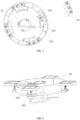
FIG. 1 is a schematic structural diagram of a lamp according to a preferred embodiment of the present application; -
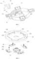
FIG. 2 is an exploded structural view of a fixing device according to a preferred embodiment of the present application; -
FIG. 3 is an exploded structural view of a fixing base in a fixing device according to a preferred embodiment of the present application; -
FIG. 4 is an exploded structural view of a connection base in a fixing device according to a preferred embodiment of the present application; -
FIG. 5 is an exploded structural view, from another viewing angle, of a connection base in a fixing device according to a preferred embodiment of the present application; and -
FIG. 6 is a schematic structural diagram of cooperation between a positioning piece and a positioning hole in a fixing device according to a preferred embodiment of the present application. - In order to make the purposes, technical solutions and advantages of the present application more clear, the present application will be described in detail below in conjunction with the accompanying drawings and specific embodiments.
- Here, it should be noted that in order to avoid obscuring the present application with unnecessary details, only the structure and/or processing steps closely related to the solutions of the present application are shown in the accompanying drawings, while other details that are not closely related to the present application are omitted.
- In addition, it should be noted that the terms "comprising", "including" or any other variations thereof are intended to cover non-exclusive inclusion, so that a process, method, article or apparatus including a series of elements includes not only these elements, but also other elements not explicitly listed, or elements inherent to such process, method, article or apparatus.
- As shown in
FIGS. 1-6 , the present application discloses alamp 100, thelamp 100 includes afixing device 101 and alamp body 102 that are convenient for installation and disassembly, one end of the fixingdevice 101 is configured to be mounted on a mounting surface, and the other end of the fixingdevice 101 is configured to be connected to thelamp body 102. For the sake of clarity, the specific structure of the fixingdevice 101 will be described in detail in the following description. - As shown in
FIGS. 2-4 , the fixingdevice 101 includes a fixingbase 10 and aconnection base 20, the fixingbase 10 is provided with afirst lead terminal 11 for connecting commercial power and a plug hole (not shown), theconnection base 20 is provided with asecond lead terminal 21 for connecting thelamp body 102, thefirst lead terminal 11 is arranged at one side of the plug hole, and theconnection base 20 is arranged at the other side of the plug hole. After theconnection base 20 is clamped to the fixingbase 10 through rotating, thesecond lead terminal 21 passes through the plug hole to be electrically connected with thefirst lead terminal 11, so as to supply power to thelamp 100. Further, aposition stopper 12 is provided at a side of the plug hole close to thefirst lead terminal 11, and theposition stopper 12 is used to prevent thefirst lead terminal 11 from rotating around the plug hole to avoid wire twisting. - As shown in
FIG. 3 , the fixingbase 10 is used to be fixed on a mounting surface, such as a wall or a ceiling, etc., a mountingcomponent 13 is arranged at the outer side of the fixingbase 10, the mountingcomponent 13 is provided with a mountinghole 131 and a mounting piece (not shown), and the mounting piece passes through the mountinghole 131 to fix the fixingbase 10 on the mounting surface. In other embodiments of the present application, the cross-section of the mountinghole 131 may be strip-shaped, and the mounting piece can move laterally along the mountinghole 131 to facilitate timely adjustment of the mounting position. Further, the extension directions of the strip-shaped mountingholes 131 ondifferent mounting components 13 may be different, and preferably, are perpendicular to each other. It can be understood that the structural stability of the fixingbase 10 can be enhanced by arranging multiple mountingcomponents 13. In the present application, it is preferable to arrange four mountingcomponents 13, and the four mountingcomponents 13 are evenly distributed on the circumferential outer side of the fixingbase 10. - The mounting
component 13 is provided with a throughgroove 14 penetrating through the mounting component, and afirst connection piece 15 is arranged in the throughgroove 14. A first limitingpiece 16 configured to support thefirst connection piece 15 is further arranged at the outer side of the fixingbase 10, the mountingcomponent 13 and the first limitingpiece 16 are coaxially arranged along the circumferential outer wall of the fixingbase 10, and two ends of thefirst connection piece 15 are fixedly connected to the mountingcomponent 13 and the first limitingpiece 16, respectively. Preferably, there are fourfirst connection pieces 15 and four first limitingpieces 16 corresponding to the mountingcomponents 13. - Specifically, the
first connection piece 15 includes afirst end 151, asecond end 152, and athird end 153 configured to connect thefirst end 151 and thesecond end 152; the size of thefirst end 151 is greater than the size of the opening of the throughgroove 14, both the size of thesecond end 152 and the size of thethird end 153 are less than the size of the opening of the throughgroove 14, and thesecond end 152 of thefirst connection piece 15 extends downward from the throughgroove 14, so that thesecond end 152 is attached to the first limitingpiece 16 and fastened to the first limitingpiece 16 by a fastening piece. Similarly, thefirst end 151 and thethird end 153 are respectively attached to the mountingcomponent 13 and the outer wall the fixingbase 10, and are fastened by fastening pieces, so as to enhance the structural stability of the fixingbase 10. The specific structure, in which thesecond end 152 is attached to the first limitingpiece 16, can be set as needed, including but not limited to setting a slot or hole structure matching with thesecond end 152 on the first limitingpiece 16. Preferably, thefirst connection piece 15 includes, but is not limited to, hardware, as long as it has strong structural strength and is not easily to be deformed. It can be understood that thefirst end 151 is provided with a slot or hole corresponding to the mountinghole 131. - As shown in
FIG. 4 , theconnection base 20 is configured to be connected to thelamp body 102. Of course, it can be understood that in other embodiments of the present application, theconnection base 20 may be integral with thelamp body 102, and thelamp body 102 may be directly connected to the fixingbase 10 as illustrated, which is not limited to this case here. Afirst accommodation cavity 22 configured to accommodate the fixingbase 10 is arranged in theconnection base 20. It can be understood that the main body of the fixingbase 10 is accommodated in thefirst accommodation cavity 22, and the mountingcomponent 13 is arranged at the outer side of thefirst accommodation cavity 22. Theconnection base 20 is partially recessed to form thefirst accommodation cavity 22, thefirst accommodation cavity 22 includes anannular wall 221, a second limitingpiece 23 is arranged at the inner side of theannular wall 221, and the second limitingpiece 23 is configured to cooperate with the first limitingpiece 16 to limit each other. Specifically, the second limitingpiece 23 includes a bearingportion 231 abutting against the first limitingpiece 16 and a stoppingportion 232 for preventing excessive rotation of the first limiting piece, and the bearingportion 231 and the stoppingportion 232 are connected and enclosed to form asecond accommodation cavity 233 configured to accommodate the first limitingpiece 16. Preferably, there are four second limitingpieces 23 corresponding to the first limitingpieces 16. - Specifically, the
second accommodation cavity 233 is provided with an opening along the circumferential direction of theannular wall 221, the opening and the stoppingportion 232 are respectively located at two sides of thebearing portion 231 along the circumferential direction of theannular wall 221. When theconnection base 20 is matched with thefixing base 10, the first limitingpiece 16 can be clamped between adjacent second limitingpieces 23, and theconnection base 20 rotates to drive the first limitingpiece 16 to rotate into thesecond accommodation cavity 233 of the second limitingpiece 23, so as to realize the clamping fit with thefixing base 10, thus completing the installation of thelamp 100. If thelamp 100 needs to be disassembled, it is only needed to reversely rotate theconnection base 20. - In the preferred embodiment of the present application, the
bearing portion 231 is provided with aguide portion 234 at the opening, theguide portion 234 is plate-shaped, and theguide portion 234 enable thesecond accommodation cavity 233 to has a tendency to gradually shrink inward from the opening, that is, the cross-sectional area of thesecond accommodation cavity 233 gradually decreases from the opening to thestopping portion 232, so as to increase the size of the opening and facilitate the first limiting piece to move along theguide portion 234 into thesecond accommodation cavity 233. - As shown in
FIG. 5 , in other embodiments of the present application, asecond connection piece 24 attached to thebearing portion 231 is arranged in thesecond accommodation cavity 233, a part of thesecond connection piece 24 is fixedly connected to thebearing portion 231, another part of thesecond connection piece 24 is fixedly connected to theconnection base 20, and thesecond connection piece 24 is used for strengthening the structural strength between thesecond accommodation cavity 233 and theconnection base 20. Preferably, thesecond connection piece 24 includes, but is not limited to, hardware, as long as it has strong structural strength and is not easily to be deformed. - In other embodiments of the present application, the bearing
portion 231 is not horizontally arranged, that is, the bearingportion 231 is higher at the opening and lower at the stoppingportion 232, so that the first limitingpiece 16 has a tendency to move towards the stoppingportion 232 in thesecond accommodation cavity 233 under the action of gravity, so as to prevent accidental detachment of thelamp body 102. - As shown in
FIG. 4 andFIG. 6 , as a preferred embodiment of the present application, theconnection base 20 can generate an indication sound of being assembled in place during the assembly process with fixingbase 10. Specifically, the first limitingpiece 16 is provided with apositioning hole 17 facing the opening of the mountingcomponent 13. In other embodiments, in the case where thefirst connection piece 15 is closer to the mountingcomponent 13, thepositioning hole 17 may be arranged at thesecond end 152 of thefirst connection piece 15, which is not limited to this here. Apositioning piece 241 facing thepositioning hole 17 is arranged in thesecond accommodation cavity 233. When the first limitingpiece 16 is clamped into thesecond accommodation cavity 233, the first limitingpiece 16 presses thepositioning piece 241 thereby elastic deformation is generated, and with the continuous movement of the first limitingpiece 16, thepositioning piece 241 is clamped into thepositioning hole 17, and a sound is generated due to vibration in the process of elasticity reset to indicate the assembly in place. On the contrary, in the process of disassembly of the fixingdevice 101 and alamp body 102, the first limitingpiece 16 reversely moves, and elastic deformation is generated on thepositioning piece 241 accompanied by a sound to indicate the completion of detachment. - In the preferred embodiment of the present application, the bearing
portion 231 is provided with aprotrusion portion 235 protruding in a direction away from thesecond accommodation cavity 233. Because the opening of thesecond accommodation cavity 233 is relatively large, the connection piece is prone to be oblique during the assembly, and theprotrusion portion 235 is configured to abut against the mountingcomponent 13 when theconnection base 20 is obliquely mounted relative to the fixingbase 10, so as to avoid wrong installation. - Further, a
third accommodation cavity 236 communicating with thesecond accommodation cavity 233 is arranged in theprotrusion portion 235, thepositioning piece 241 is partially accommodated in thethird accommodation cavity 236, a through hole is formed in thesecond connection piece 24 corresponding to thethird accommodation cavity 236, and thepositioning piece 241 extends into thesecond accommodation cavity 233 from thethird accommodation cavity 236 by passing through the bearingportion 231 and thesecond connection piece 24. Anelastic piece 242 for resetting thepositioning piece 241 is further arranged in thethird accommodation cavity 236. Theelastic piece 242 may be a spring, and theelastic piece 242 is sleeved on thepositioning piece 241 and accommodated in thethird accommodation cavity 236. When thepositioning piece 241 is pressed by the first limitingpiece 16, theelastic piece 242 receives pressure and contracts with thepositioning piece 241 into thethird accommodation cavity 236. When the lamp is assembled in place, thepositioning piece 241 is reset under the elastic force of theelastic piece 242 and clamped into thepositioning hole 17. - In summary, in the present application, the
protrusion portion 235 is provided in thelamp 100, so that theconnection base 20 and the fixingbase 10 are prevented from being obliquely clamped in the assembly process of the lamp, and an indicating sound is generated when the lamp is assembled in place. - The above embodiments are only used to illustrate the technical solutions of the present application, but not restrictive. Although the present application has been described in detail with reference to the preferred embodiments, it should be understood by those skilled in the art that the technical solutions of the present application can be modified or replaced by equivalents without departing from the spirit and scope of the technical solutions of the present application.
Claims (14)
- A fixing device for fixing a lamp, comprising a fixing base and a connection base, the connection base being clamped to the fixing base through rotating, wherein a mounting component for fixing the fixing base is arranged at an outer side of the fixing base, a first connection piece is arranged in the mounting component, one end of the first connection piece is fixed with the mounting component, other end of the first connection piece is provided with a positioning hole facing an opening of the mounting component, a positioning piece facing the positioning hole is arranged in the connection base, the connection base drives the positioning piece to be clamped to or detached from the positioning hole during rotating, and a sound is generated during a clamping or detaching process of the positioning piece.
- The fixing device according to claim 1, wherein a first limiting piece for supporting the first connection piece is further arranged at the outer side of the fixing base, and two ends of the first connection piece are fixedly connected to the mounting component and the first limiting piece, respectively.
- The fixing device according to claim 2, wherein a first accommodation cavity for accommodating the fixing base is arranged in the connection base, the first accommodation cavity comprises an annular wall provided with a second limiting piece, the second limiting piece is configured to cooperate with the first limiting piece to limit each other, the second limiting piece comprises a bearing portion abutting against the first limiting piece and a stopping portion for preventing excessive rotation of the first limiting piece, and the bearing portion and the stopping portion are enclosed to form a second accommodation cavity configured to accommodate the first limiting piece.
- The fixing device according to claim 3, wherein the bearing portion is not horizontally arranged, so that the first limiting piece has a tendency to move towards the stopping portion in the accommodation cavity.
- The fixing device according to claim 3, wherein the second accommodation cavity is provided with an opening along a circumferential direction of the annular wall, the opening and the stopping portion are respectively located at two sides of the bearing portion along the circumferential direction of the annular wall, the bearing portion is provided with a guide portion at the opening, and the guide portion enables the second accommodation cavity to has a tendency to gradually shrink inward from the opening.
- The fixing device according to claim 3, wherein the bearing portion is provided with a protrusion portion away from the second accommodation cavity, and the protrusion portion is configured to abut against the mounting component when the connection base is obliquely mounted relative to the fixing base.
- The fixing device according to claim 6, wherein a third accommodation cavity communicated with the second accommodation cavity is arranged in the protrusion portion, the positioning piece is partially accommodated in the third accommodation cavity, and an elastic piece configured to reset the positioning piece is further arranged in the third accommodation cavity.
- The fixing device according to claim 7, wherein a second connection piece attached to the bearing portion is arranged in the second accommodation cavity, a part of the second connection piece is fixedly connected to the bearing portion, another part of the second connection piece is fixedly connected to the connection base, and the positioning piece extends into the second accommodation cavity from the third accommodation cavity by passing through the bearing portion and the second connection piece.
- The fixing device according to claim 1, wherein the fixing base is provided with a first lead terminal for connecting commercial power, the connection base is provided with a second lead terminal for connecting an electrical equipment, and after the connection base is clamped to the fixing base through rotating, the first lead terminal is electrically connected with the second lead terminal.
- A fixing base, used for cooperating with a connection base and fixing a lamp, a positioning piece being arranged in the connection piece, wherein a mounting component for fixing the fixing base is arranged at an outer side of the fixing base, a first connection piece is arranged in the mounting component, one end of the first connection piece is fixed with the mounting component, other end of the first connection piece is provided with a positioning hole facing an opening of the mounting component, the connection base drives the positioning piece to be clamped to or detached from the positioning hole during rotating, and a sound is generated during a clamping or detaching process of the positioning piece.
- The fixing base according to claim 10, wherein a first limiting piece configured to support the first connection piece is further arranged at the outer side of the fixing base, and two ends of the first connection piece are fixedly connected to the mounting component and the first limiting piece, respectively.
- A connection base, arranged in a lamp and used for cooperating with a fixing base, a positioning hole being arranged in the fixing base, wherein a positioning piece for cooperating with the positioning hole is arranged in the connection base, the connection base drives the positioning piece to be clamped to or detached from the positioning hole during rotating, and a sound is generated during a clamping or detaching process of the positioning piece.
- The connection base according to claim 12, wherein a first accommodation cavity configured to accommodate the fixing base is arranged in the connection base, the first accommodation cavity comprises an annular wall provided with a second limiting piece, and the second limiting piece is configured to cooperate with the first limiting piece of the fixing base to limit each other.
- The connection base according to claim 13, wherein the second limiting piece comprises a bearing portion abutting against the first limiting piece and a stopping portion for preventing excessive rotation of the first limiting piece, the bearing portion and the stopping portion are enclosed to form a second accommodation cavity configured to accommodate the first limiting piece, and the positioning piece is arranged on the bearing portion in the second accommodation cavity.
Applications Claiming Priority (3)
| Application Number | Priority Date | Filing Date | Title |
|---|---|---|---|
| CN202111147588.XA CN113669697A (en) | 2021-09-29 | 2021-09-29 | Fixing base, connecting base and fixing device |
| CN202122370197.6U CN216079689U (en) | 2021-09-29 | 2021-09-29 | Fixing seat, connecting seat and fixing device |
| PCT/CN2022/112943 WO2023051071A1 (en) | 2021-09-29 | 2022-08-17 | Fixing seat, connecting seat and fixing device |
Publications (2)
| Publication Number | Publication Date |
|---|---|
| EP4403824A1 true EP4403824A1 (en) | 2024-07-24 |
| EP4403824A4 EP4403824A4 (en) | 2025-02-19 |
Family
ID=85781269
Family Applications (1)
| Application Number | Title | Priority Date | Filing Date |
|---|---|---|---|
| EP22874466.0A Pending EP4403824A4 (en) | 2021-09-29 | 2022-08-17 | MOUNTING SEAT, CONNECTING SEAT AND FASTENING DEVICE |
Country Status (3)
| Country | Link |
|---|---|
| US (1) | US20240240776A1 (en) |
| EP (1) | EP4403824A4 (en) |
| WO (1) | WO2023051071A1 (en) |
Families Citing this family (1)
| Publication number | Priority date | Publication date | Assignee | Title |
|---|---|---|---|---|
| CN118640419A (en) * | 2024-08-16 | 2024-09-13 | 浙江百康光学股份有限公司 | A temporary atmosphere light |
Family Cites Families (10)
| Publication number | Priority date | Publication date | Assignee | Title |
|---|---|---|---|---|
| CN103115298B (en) * | 2011-12-30 | 2016-09-14 | 欧普照明股份有限公司 | A kind of lamp affixed to the ceiling |
| WO2019085764A1 (en) * | 2017-10-30 | 2019-05-09 | 苏州欧普照明有限公司 | Installation assembly of ceiling lighting lamp, ceiling lighting lamp and ceiling light |
| CN210567919U (en) * | 2018-09-05 | 2020-05-19 | 昕诺飞控股有限公司 | Lamp fixing seat and lamp connecting seat |
| CN111520650B (en) * | 2019-02-02 | 2022-03-11 | 松下知识产权经营株式会社 | Lamp fixing device |
| CN209876820U (en) * | 2019-05-24 | 2019-12-31 | 松下知识产权经营株式会社 | Fixtures for lamps |
| CN209977855U (en) * | 2019-06-18 | 2020-01-21 | 湖南第一师范学院 | A multifunctional architectural decorative lamp |
| CN110762492A (en) * | 2019-11-20 | 2020-02-07 | 欧普照明股份有限公司 | Fixtures, Fixtures for Lamps, and Lamps |
| CN213777597U (en) * | 2021-01-22 | 2021-07-23 | 杭州同晟电器有限公司 | An energy-saving LED lampshade |
| CN113669697A (en) * | 2021-09-29 | 2021-11-19 | 苏州欧普照明有限公司 | Fixing base, connecting base and fixing device |
| CN216079689U (en) * | 2021-09-29 | 2022-03-18 | 苏州欧普照明有限公司 | Fixing seat, connecting seat and fixing device |
-
2022
- 2022-08-17 WO PCT/CN2022/112943 patent/WO2023051071A1/en not_active Ceased
- 2022-08-17 EP EP22874466.0A patent/EP4403824A4/en active Pending
-
2024
- 2024-03-28 US US18/619,349 patent/US20240240776A1/en active Pending
Also Published As
| Publication number | Publication date |
|---|---|
| EP4403824A4 (en) | 2025-02-19 |
| WO2023051071A1 (en) | 2023-04-06 |
| US20240240776A1 (en) | 2024-07-18 |
Similar Documents
| Publication | Publication Date | Title |
|---|---|---|
| US11041613B1 (en) | Ceiling lamp | |
| US20240240776A1 (en) | Fixing base, connection base and fixing device | |
| US11857108B2 (en) | Flange assembly for achieving quick replacement of a wok and wok assembly device | |
| US10619643B2 (en) | Ceiling fan assembly | |
| CN210717216U (en) | Ceiling lamp connecting seat and ceiling lamp | |
| CN110566911A (en) | LED lamp clamping and mounting structure | |
| CN111520650A (en) | Fixtures for lamps | |
| CN216079689U (en) | Fixing seat, connecting seat and fixing device | |
| CN209819853U (en) | Supporting seat, air conditioner display assembly and wall hanging machine | |
| CN109373293B (en) | Quick-release structure and lamp | |
| CN108018682B (en) | A screw cover and washing machine using the screw cover | |
| US11346354B2 (en) | Downrod assembly and ceiling fan | |
| CN217691452U (en) | Battery assembly structure and outdoor air conditioner | |
| JP2008277191A (en) | Wiring equipment | |
| CN113669697A (en) | Fixing base, connecting base and fixing device | |
| CN204611708U (en) | Be connected to the monitor stand of spotlight shade | |
| CN224121123U (en) | LED light source lamp base plate fixed knot constructs | |
| CN210345374U (en) | LED lamp clamping and mounting structure | |
| CN219696822U (en) | Public first mounting structure of power and cooking utensil | |
| CN219912873U (en) | Buckle structure and lamp | |
| CN223987276U (en) | A controller housing | |
| CN220606038U (en) | Mounting bracket, microphone assembly and wind turbine generator monitoring system | |
| JP2015125916A (en) | lighting equipment | |
| CN217466632U (en) | Composite insulator adhesion detection device | |
| CN222014957U (en) | Display equipment |
Legal Events
| Date | Code | Title | Description |
|---|---|---|---|
| STAA | Information on the status of an ep patent application or granted ep patent |
Free format text: STATUS: THE INTERNATIONAL PUBLICATION HAS BEEN MADE |
|
| PUAI | Public reference made under article 153(3) epc to a published international application that has entered the european phase |
Free format text: ORIGINAL CODE: 0009012 |
|
| STAA | Information on the status of an ep patent application or granted ep patent |
Free format text: STATUS: REQUEST FOR EXAMINATION WAS MADE |
|
| 17P | Request for examination filed |
Effective date: 20240416 |
|
| AK | Designated contracting states |
Kind code of ref document: A1 Designated state(s): AL AT BE BG CH CY CZ DE DK EE ES FI FR GB GR HR HU IE IS IT LI LT LU LV MC MK MT NL NO PL PT RO RS SE SI SK SM TR |
|
| DAV | Request for validation of the european patent (deleted) | ||
| DAX | Request for extension of the european patent (deleted) | ||
| A4 | Supplementary search report drawn up and despatched |
Effective date: 20250122 |
|
| RIC1 | Information provided on ipc code assigned before grant |
Ipc: F21V 23/06 20060101ALI20250116BHEP Ipc: F21V 17/16 20060101ALI20250116BHEP Ipc: F21V 17/14 20060101ALI20250116BHEP Ipc: F21S 8/04 20060101ALI20250116BHEP Ipc: F21V 21/03 20060101ALI20250116BHEP Ipc: F21V 21/02 20060101AFI20250116BHEP |