EP4403809A1 - Electric valve - Google Patents
Electric valve Download PDFInfo
- Publication number
- EP4403809A1 EP4403809A1 EP22869705.8A EP22869705A EP4403809A1 EP 4403809 A1 EP4403809 A1 EP 4403809A1 EP 22869705 A EP22869705 A EP 22869705A EP 4403809 A1 EP4403809 A1 EP 4403809A1
- Authority
- EP
- European Patent Office
- Prior art keywords
- valve
- driving shaft
- projection
- connecting member
- valve member
- Prior art date
- Legal status (The legal status is an assumption and is not a legal conclusion. Google has not performed a legal analysis and makes no representation as to the accuracy of the status listed.)
- Pending
Links
Images




Classifications
-
- F—MECHANICAL ENGINEERING; LIGHTING; HEATING; WEAPONS; BLASTING
- F16—ENGINEERING ELEMENTS AND UNITS; GENERAL MEASURES FOR PRODUCING AND MAINTAINING EFFECTIVE FUNCTIONING OF MACHINES OR INSTALLATIONS; THERMAL INSULATION IN GENERAL
- F16K—VALVES; TAPS; COCKS; ACTUATING-FLOATS; DEVICES FOR VENTING OR AERATING
- F16K31/00—Actuating devices; Operating means; Releasing devices
- F16K31/02—Actuating devices; Operating means; Releasing devices electric; magnetic
- F16K31/04—Actuating devices; Operating means; Releasing devices electric; magnetic using a motor
-
- F—MECHANICAL ENGINEERING; LIGHTING; HEATING; WEAPONS; BLASTING
- F16—ENGINEERING ELEMENTS AND UNITS; GENERAL MEASURES FOR PRODUCING AND MAINTAINING EFFECTIVE FUNCTIONING OF MACHINES OR INSTALLATIONS; THERMAL INSULATION IN GENERAL
- F16K—VALVES; TAPS; COCKS; ACTUATING-FLOATS; DEVICES FOR VENTING OR AERATING
- F16K31/00—Actuating devices; Operating means; Releasing devices
- F16K31/02—Actuating devices; Operating means; Releasing devices electric; magnetic
- F16K31/04—Actuating devices; Operating means; Releasing devices electric; magnetic using a motor
- F16K31/047—Actuating devices; Operating means; Releasing devices electric; magnetic using a motor characterised by mechanical means between the motor and the valve, e.g. lost motion means reducing backlash, clutches, brakes or return means
-
- F—MECHANICAL ENGINEERING; LIGHTING; HEATING; WEAPONS; BLASTING
- F16—ENGINEERING ELEMENTS AND UNITS; GENERAL MEASURES FOR PRODUCING AND MAINTAINING EFFECTIVE FUNCTIONING OF MACHINES OR INSTALLATIONS; THERMAL INSULATION IN GENERAL
- F16K—VALVES; TAPS; COCKS; ACTUATING-FLOATS; DEVICES FOR VENTING OR AERATING
- F16K1/00—Lift valves or globe valves, i.e. cut-off apparatus with closure members having at least a component of their opening and closing motion perpendicular to the closing faces
- F16K1/02—Lift valves or globe valves, i.e. cut-off apparatus with closure members having at least a component of their opening and closing motion perpendicular to the closing faces with screw-spindle
-
- F—MECHANICAL ENGINEERING; LIGHTING; HEATING; WEAPONS; BLASTING
- F16—ENGINEERING ELEMENTS AND UNITS; GENERAL MEASURES FOR PRODUCING AND MAINTAINING EFFECTIVE FUNCTIONING OF MACHINES OR INSTALLATIONS; THERMAL INSULATION IN GENERAL
- F16K—VALVES; TAPS; COCKS; ACTUATING-FLOATS; DEVICES FOR VENTING OR AERATING
- F16K1/00—Lift valves or globe valves, i.e. cut-off apparatus with closure members having at least a component of their opening and closing motion perpendicular to the closing faces
- F16K1/32—Details
- F16K1/34—Cutting-off parts, e.g. valve members, seats
- F16K1/36—Valve members
-
- F—MECHANICAL ENGINEERING; LIGHTING; HEATING; WEAPONS; BLASTING
- F16—ENGINEERING ELEMENTS AND UNITS; GENERAL MEASURES FOR PRODUCING AND MAINTAINING EFFECTIVE FUNCTIONING OF MACHINES OR INSTALLATIONS; THERMAL INSULATION IN GENERAL
- F16K—VALVES; TAPS; COCKS; ACTUATING-FLOATS; DEVICES FOR VENTING OR AERATING
- F16K1/00—Lift valves or globe valves, i.e. cut-off apparatus with closure members having at least a component of their opening and closing motion perpendicular to the closing faces
- F16K1/32—Details
- F16K1/48—Attaching valve members to screw-spindles
-
- F—MECHANICAL ENGINEERING; LIGHTING; HEATING; WEAPONS; BLASTING
- F16—ENGINEERING ELEMENTS AND UNITS; GENERAL MEASURES FOR PRODUCING AND MAINTAINING EFFECTIVE FUNCTIONING OF MACHINES OR INSTALLATIONS; THERMAL INSULATION IN GENERAL
- F16K—VALVES; TAPS; COCKS; ACTUATING-FLOATS; DEVICES FOR VENTING OR AERATING
- F16K27/00—Construction of housing; Use of materials therefor
- F16K27/02—Construction of housing; Use of materials therefor of lift valves
- F16K27/029—Electromagnetically actuated valves
-
- F—MECHANICAL ENGINEERING; LIGHTING; HEATING; WEAPONS; BLASTING
- F16—ENGINEERING ELEMENTS AND UNITS; GENERAL MEASURES FOR PRODUCING AND MAINTAINING EFFECTIVE FUNCTIONING OF MACHINES OR INSTALLATIONS; THERMAL INSULATION IN GENERAL
- F16K—VALVES; TAPS; COCKS; ACTUATING-FLOATS; DEVICES FOR VENTING OR AERATING
- F16K31/00—Actuating devices; Operating means; Releasing devices
- F16K31/44—Mechanical actuating means
- F16K31/50—Mechanical actuating means with screw-spindle or internally threaded actuating means
- F16K31/508—Mechanical actuating means with screw-spindle or internally threaded actuating means the actuating element being rotatable, non-rising, and driving a non-rotatable axially-sliding element
-
- Y—GENERAL TAGGING OF NEW TECHNOLOGICAL DEVELOPMENTS; GENERAL TAGGING OF CROSS-SECTIONAL TECHNOLOGIES SPANNING OVER SEVERAL SECTIONS OF THE IPC; TECHNICAL SUBJECTS COVERED BY FORMER USPC CROSS-REFERENCE ART COLLECTIONS [XRACs] AND DIGESTS
- Y02—TECHNOLOGIES OR APPLICATIONS FOR MITIGATION OR ADAPTATION AGAINST CLIMATE CHANGE
- Y02B—CLIMATE CHANGE MITIGATION TECHNOLOGIES RELATED TO BUILDINGS, e.g. HOUSING, HOUSE APPLIANCES OR RELATED END-USER APPLICATIONS
- Y02B30/00—Energy efficient heating, ventilation or air conditioning [HVAC]
- Y02B30/70—Efficient control or regulation technologies, e.g. for control of refrigerant flow, motor or heating
Definitions
- the present invention relates to an electric valve.
- Patent Literature 1 discloses an example of an electric valve according to the related art.
- the electric valve disclosed in Patent Literature 1 includes a valve chamber, a first passage connected to the valve chamber via a valve port, a second passage connected to the valve chamber, and a valve member facing the valve port in an up-and-down direction.
- the valve member is moved in the up-and-down direction along with rotation of a rotor.
- the electric valve controls the flow rate of refrigerant flowing from the first passage to the second passage and the flow rate of refrigerant flowing from the second passage to the first passage.
- the rotation of the rotor is transmitted to a driving shaft.
- the driving shaft includes an external thread.
- the external thread of the driving shaft is screwed into an internal thread of a guide member.
- the driving shaft rotates and is moved downward by a screw-feed action.
- the valve member is pushed downward by the driving shaft and closes the valve port.
- the driving shaft rotates and is moved upward by the screw-feed action.
- the valve member is pushed upward by a valve opening spring and opens the valve port.
- Patent Literature 1 Japanese Unexamined Patent Application Publication No. 2018-135908
- valve member when refrigerant pressure in the first passage is higher than refrigerant pressure in the second passage, an upward force is applied to the valve member.
- the driving shaft pushes the valve member downward against the upward force and against a force exerted by the valve opening spring to push the valve member upward, closing the valve port.
- a downward force is applied to the valve member.
- the valve opening spring pushes the valve member upward against the downward force, opening the valve port.
- Increasing the diameter of the valve port effectively increases the flow rate of refrigerant flowing in the electric valve.
- the force is referred to as "spring force”.
- the upward force also increases when the diameter of the valve port increases, it is necessary to also increase the force exerted by the driving shaft to push the valve member downward against the upward force and the spring force. Consequently, forces applied to components, such as the driving shaft, increase, accelerating the wear of the components and reducing the durability of the electric valve.
- the driving shaft can pull the valve member upward to open the valve port by securing the valve member to the driving shaft.
- the valve member rotates together with the driving shaft and slides on a valve seat, which encloses the valve port, in the rotational direction. This accelerates the wear of the valve member and the valve seat, reducing the durability of the electric valve.
- an electric valve includes a valve body having a valve port, a valve member facing the valve port, a rotor rotatable with respect to the valve body, and a driving shaft to which rotation of the rotor is transmitted.
- the driving shaft moves toward or away from the valve port.
- the driving shaft pushes the valve member when moving toward the valve port.
- the driving shaft pulls the valve member when moving away from the valve port.
- the driving shaft is rotatable with respect to the valve member.
- the electric valve further includes a connecting member mounted on the valve member.
- one of the driving shaft and the connecting member includes a projection
- the other of the driving shaft and the connecting member includes a projection receiving portion on which the projection hooks when the driving shaft moves away from the valve port.
- the connecting member is mounted on the valve member and the valve member is rotatable with respect to the connecting member.
- the connecting member includes a base portion that has a flat plate-like shape and that is mounted on the valve member, and elastic tabs that extend from a peripheral edge of the base portion toward the driving shaft and that is capable of elastically deforming in a direction away from a center of the base portion.
- each of the elastic tabs includes the projection that projects toward the center of the base portion.
- the projection receiving portion is disposed at a first end of the driving shaft, and the first end of the driving shaft is surrounded by the elastic tabs.
- the electric valve further includes a connecting member mounted on the driving shaft.
- one of the valve member and the connecting member includes a projection
- the other of the valve member and the connecting member includes a projection receiving portion on which the projection hooks when the connecting member moves away from the valve port together with the driving shaft.
- the driving shaft when the rotation of the rotor is transmitted to the driving shaft, the driving shaft moves toward or away from the valve port while rotating.
- the driving shaft pushes the valve member when moving toward the valve port and pulls the valve member when moving away from the valve port, and the driving shaft is rotatable with respect to the valve member.
- the driving shaft pulls the valve member away from the valve port, enabling the valve port to open without relying on a valve opening spring that pushes the valve member away from the valve port.
- the driving shaft since the driving shaft is rotatable with respect to the valve member, the driving shaft rotates with respect to the valve member when the valve member is in contact with the valve seat that encloses the valve port, inhibiting the valve member from sliding on the valve seat.
- the electric valve has a valve port with a large diameter while ensuring durability.
- An electric valve 1 according to a first embodiment of the present invention is described below with reference to Fig. 1 to Fig. 3 .
- the electric valve 1 according to the embodiment is used, for example, for controlling the flow rate of refrigerant in a refrigeration cycle system of an air conditioner.
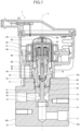
- Fig. 1 is a sectional view of an electric valve according to the first embodiment of the present invention.
- Fig. 2 is an enlarged sectional view of a part (mainly a valve member, a connecting member, and a driving section) of the electric valve in Fig. 1 .
- a stator unit is not illustrated.
- Fig. 3 is an orthographic projection diagram of the connecting member of the electric valve in Fig. 1 with six views.
- the upper diagram is a plan view
- the lower diagram is a bottom view
- the diagram between the upper and lower diagrams is a front view.
- the left diagram is a left-side view
- the right diagram is a back view
- the diagram adjacent to the right diagram is a right-side view.
- the electric valve 1 includes a valve body 10, a holder 20, a valve-member supporting member 25, a can 30, a valve member 40, a connecting member 45, a driving section 50, and a stator unit 80.
- the valve body 10 has a rectangular parallelepiped shape.
- the valve body 10 includes a valve chamber 13 and a valve port 14 connected to the valve chamber 13.
- the valve port 14 is enclosed by a valve seat 15.
- the valve body 10 includes a first passage 17 and a second passage 18.
- the first passage 17 includes a first end that is connected to the valve chamber 13 via the valve port 14 and a second end that is open on a right surface 10a of the valve body 10.
- the second passage 18 includes a first end that is connected to the valve chamber 13 and a second end that is open on a left surface 10b of the valve body 10.
- the valve body 10 has a mounting hole 19.
- the mounting hole 19 is located in an upper surface 10c of the valve body 10.
- the mounting hole 19 includes an inner circumferential surface on which an internal thread is formed.
- the valve chamber 13 is open to a bottom surface 19a of the mounting hole 19.
- the holder 20 has a circular cylindrical shape.
- the holder 20 includes an outer circumferential surface on which an external thread is formed.
- the external thread is disposed in the lower part of the outer circumferential surface.
- the external thread of the holder 20 is screwed into the internal thread of the mounting hole 19 of the valve body 10.
- the holder 20 is mounted on the valve body 10 by a screw structure.
- the valve-member supporting member 25 has a circular cylindrical shape.
- the valve-member supporting member 25 is disposed inside the mounting hole 19 and interposed between the valve body 10 and the holder 20.
- the valve-member supporting member 25 includes a lower portion press-fitted into the valve chamber 13.
- the valve-member supporting member 25 has an outer circumferential surface on which an annular flat surface 25a facing downward is formed.
- the annular flat surface 25a is in contact with the bottom surface 19a of the mounting hole 19.
- the valve-member supporting member 25 supports the valve member 40 to be movable in an up-and-down direction (a direction of an axis L) .
- the can 30 has a circular cylindrical shape.
- the can 30 is closed at the upper end and is open at the lower end.
- the lower end of the can 30 is bonded to the outer peripheral edge of a joint member 35 having a circular annular plate-like shape.
- the holder 20 includes an upper portion 20a disposed inside the joint member 35.
- the inner peripheral edge of the joint member 35 is bonded to the holder 20.
- the can 30 is secured to the valve body 10 via the joint member 35 and the holder 20.
- the valve member 40 includes a stem 41, a valve portion 42, and a ball receiving portion 43.
- the stem 41 has a circular columnar shape.
- the stem 41 is disposed inside the valve-member supporting member 25.
- the stem 41 is supported by the valve-member supporting member 25 and can move in the up-and-down direction.
- the valve portion 42 is connected to the lower end of the stem 41.
- the valve portion 42 has a circular annular shape.
- the valve portion 42 projects radially outward from the outer circumferential surface of the stem 41.
- the valve portion 42 faces the valve port 14 in the up-and-down direction.
- the ball receiving portion 43 includes a flat plate portion 43a having a circular shape and a projecting portion 43b connected to the lower surface of the flat plate portion 43a.
- the flat plate portion 43a includes an upper surface on which a recess having a conical shape is formed.
- the projecting portion 43b is fitted into a hole 41b provided on an upper end surface 41a of the stem 41.
- the projecting portion 43b is secured to the stem 41.
- the valve portion 42 moving toward and away from the valve port 14 causes the valve member 40 to change the opening area of the valve port 14 in a stepless (including a substantially stepless) manner.
- the minimum area of the valve member 40 is zero (i.e., a state where the valve port 14 is closed).
- the minimum area of the valve port 14 may be greater than zero (i.e., a state where the valve port 14 is slightly open).
- the connecting member 45 includes a base portion 46 and elastic tabs 47.
- the base portion 46 has a disc shape.
- the connecting member 45 includes three elastic tabs 47 arranged at regular angular intervals in the circumferential direction of the base portion 46.
- Each of the elastic tabs 47 extends upward from the peripheral edge of the base portion 46.
- Each of the elastic tabs 47 includes a main portion 48 and a projection 49.
- the main portion 48 has a rectangular frame shape.
- the main portion 48 is at a right angle to the base portion 46.
- the lower side of the main portion 48 is connected to the peripheral edge of the base portion 46.
- the projection 49 has a plate-like shape with a small width and extends downward from the upper side of the main portion 48.
- the projection 49 is bent in an S-shape.
- the lower end of the projection 49 is disposed close to the center of the base portion 46 with respect to the main portion 48.
- the shape of the connecting member 45 has rotational symmetry with the axis of symmetry passing through the center of the base portion 46.
- the connecting member 45 is formed by pressing a metal plate.
- the connecting member 45 is mounted on the valve member 40. Specifically, the lower surface of the base portion 46 of the connecting member 45 is in contact with the upper end surface 41a of the stem 41, and the projecting portion 43b of the ball receiving portion 43 is inserted into a through hole 46a that is provided at the center of the base portion 46. The base portion 46 is held between the upper end surface 41a of the stem 41 and the flat plate portion 43a of the ball receiving portion 43.
- the ball receiving portion 43 also serves as a member for mounting the connecting member 45 on the valve member 40.
- the connecting member 45 may be bonded to the valve member 40 by adhesive and the like.
- the driving section 50 moves the valve member 40 in the up-and-down direction.
- the driving section 50 includes a rotor 51, a permanent magnet 55, a planetary gear mechanism 60, a guide member 68, a driving shaft 70, a ball 76, and a valve opening spring 77.
- the rotor 51 has a circular cylindrical shape.
- the rotor 51 has an outer diameter smaller than the inner diameter of the can 30.
- the rotor 51 is rotatably disposed inside the can 30.
- the rotor 51 includes an upper end to which a connecting plate 52 is bonded.
- the connecting plate 52 has a circular shape and closes the upper end of the rotor 51.
- a rotor shaft 53 extends through the center of the connecting plate 52.
- the rotor 51 is connected to the rotor shaft 53 via the connecting plate 52.
- the rotor shaft 53 rotates together with the rotor 51.
- the rotor 51 includes North (N) poles and South (S) poles.
- the N and S poles extend in the up-and-down direction.
- the N and S poles are alternately arranged in the circumferential direction on the outer circumferential surface of the rotor 51.
- the permanent magnet 55 is located inside the can 30 and above the rotor 51.
- the permanent magnet 55 has a disc shape.
- the permanent magnet 55 is secured to the upper end of the rotor shaft 53.
- the permanent magnet 55 is disposed coaxially with the rotor 51 and rotates together with the rotor 51.
- a magnetic shielding member 56 having a disc shape is disposed between the rotor 51 and the permanent magnet 55.
- the magnetic shielding member 56 is made of soft magnetic material with relatively high permeability, such as silicon iron or similar materials.
- the magnetic shielding member 56 is secured to the rotor shaft 53.
- the magnetic shielding member 56 absorbs magnetic flux generated by the rotor 51.
- the magnetic shielding member 56 inhibits the magnetic field generated by the permanent magnet 55 from being distorted by the magnetic field generated by the rotor 51.
- the permanent magnet 55 includes an N pole and an S pole.
- the permanent magnet 55 includes two parts divided by its diameter, with the N pole disposed in one of the two parts, and the S pole disposed in the other.
- the planetary gear mechanism 60 is disposed inside the rotor 51.
- the planetary gear mechanism 60 includes a gear case 61, a fixed ring gear 62, a sun gear 63, planetary gears 64, a carrier 65, an output gear 66, and an output shaft 67.
- the gear case 61 has a circular cylindrical shape.
- the gear case 61 includes a lower end that is bonded to and coaxially with the upper portion 20a of the holder 20.
- the fixed ring gear 62 is an internal gear.
- the fixed ring gear 62 is fixed to the upper end of the gear case 61.
- the sun gear 63 is disposed coaxially with the connecting plate 52.
- the sun gear 63 is integrated with the connecting plate 52.
- the rotor shaft 53 extends through the sun gear 63.
- the sun gear 63 rotates together with the rotor 51 and the connecting plate 52.
- the planetary gears 64 are interposed between the fixed ring gear 62 and the sun gear 63.
- the carrier 65 has a disc shape.
- the rotor shaft 53 extends through the center of the carrier 65.
- the carrier 65 can rotate around the rotor shaft 53, which serves as the rotational axis.
- the carrier 65 supports the planetary gears 64 to be rotatable.
- the output gear 66 has a circular cylindrical shape with a bottom.
- the output gear 66 is an internal gear.
- the planetary gears 64 are interposed between the output gear 66 and the sun gear 63.
- the output shaft 67 has a circular columnar shape.
- the output shaft 67 has an upper portion that is press-fitted into a hole formed in the bottom of the output gear 66.
- the output shaft 67 has a lower portion in which a slit 67a extending in the up-and-down direction is formed.
- the guide member 68 has a circular cylindrical shape.
- the guide member 68 is disposed inside the upper portion 20a of the holder 20.
- the guide member 68 includes an inner circumferential surface on which an internal thread 68c is formed.
- the internal thread 68c is disposed in the lower part of the inner circumferential surface.
- the output shaft 67 is disposed inside the guide member 68.
- the guide member 68 supports the output shaft 67 to be rotatable.
- the driving shaft 70 is formed, for example, by cutting a metal pole having a circular columnar shape.
- the driving shaft 70 includes a first portion 71, a second portion 72, a third portion 73, and a projection receiving portion 74.
- the first portion 71 has a rectangular flat plate-like shape.
- the first portion 71 has a thickness slightly smaller than the width of the slit 67a of the output shaft 67.
- the first portion 71 is disposed inside the slit 67a of the output shaft 67 and can move in the up-and-down direction.
- the slit 67a and the first portion 71 enable the driving shaft 70 to move in the up-and-down direction with respect to the output shaft 67 while transmitting the rotation of the output shaft 67 to the driving shaft 70.
- the second portion 72 has a circular columnar shape.
- the second portion 72 is connected to the lower end of the first portion 71.
- the second portion 72 includes an outer circumferential surface on which an external thread 72c is formed.
- the external thread 72c is screwed into the internal thread 68c of the guide member 68.
- the guide member 68 may include an external thread
- the driving shaft 70 may include an internal thread.
- the third portion 73 has a disc shape.
- the third portion 73 is connected to and coaxially with the lower end of the second portion 72.
- the third portion 73 has an outer diameter larger than the outer diameter of the second portion 72.
- the third portion 73 includes a lower surface on which a recess having a conical shape is formed, and the ball 76 is bonded to the third portion 73 at the recess.
- the ball 76 is in contact with the flat plate portion 43a of the ball receiving portion 43 at the recess of the flat plate portion 43a.
- the projection receiving portion 74 has a circular annular shape.
- the projection receiving portion 74 projects radially outward from the outer circumferential surface of the third portion 73.
- the outer diameter of the projection receiving portion 74 is smaller than a circle C1 inscribed on each of the elastic tabs 47 of the connecting member 45 and larger than a circle C2 inscribed on each projection 49 of the connecting member 45 ( Fig. 3 ).
- the third portion 73 and the projection receiving portion 74 serve as an end (a first end) of the driving shaft 70 on the valve member 40 side.
- the third portion 73 and the projection receiving portion 74 are disposed in a space defined by the elastic tabs 47 of the connecting member 45 and are surrounded by the elastic tabs 47.
- the third portion 73 faces the base portion 46 of the connecting member 45 in the up-and-down direction with a space in between.
- the projection receiving portion 74 is located beneath each projection 49 of the elastic tabs 47, and each projection 49 hooks on the projection receiving portion 74.
- each projection 49 overlaps the projection receiving portion 74 as viewed from above, and the lower end of each projection 49 is in light contact with the projection receiving portion 74 in the up-and-down direction or is slightly spaced from the projection receiving portion 74 in the up-and-down direction.
- each projection 49 hooks on the projection receiving portion 74 and is rotatable with respect to the projection receiving portion 74.
- the projections 49 hook on the projection receiving portion 74 when the driving shaft 70 moves upward, and the driving shaft 70 can rotate around the axis L with respect to the connecting member 45.
- the valve opening spring 77 is disposed between the valve-member supporting member 25 and the base portion 46 of the connecting member 45.
- the valve opening spring 77 is a compression coil spring.
- the valve opening spring 77 pushes the valve member 40 upward via the connecting member 45.
- the valve opening spring 77 may be omitted in the electric valve 1.
- the stator unit 80 includes a case 81, a stator 82, and a circuit board 83.
- the case 81 is made of synthetic resin.
- the case 81 has a box shape.
- the case 81 houses the stator 82 and the circuit board 83.
- the stator 82 and the circuit board 83 is secured to the case 81 by screws.
- the stator 82 has a circular cylindrical shape.
- the can 30 is disposed inside the stator 82.
- the stator 82 and the rotor 51 are members of a stepping motor.
- the angle sensor 84 is a magnetic angle sensor.
- the angle sensor 84 is mounted on the lower surface of the circuit board 83.
- the angle sensor 84 is located above the can 30.
- the angle sensor 84 faces the permanent magnet 55 in the up-and-down direction with the can 30 in between.
- the angle sensor 84 detects the direction and the magnitude of the magnetic field passing through the angle sensor 84.
- the rotational angle of the permanent magnet 55 can be obtained based on electric signals output by the angle sensor 84.
- the respective central axes of the valve port 14, the holder 20, the valve-member supporting member 25, the can 30, the valve member 40, the connecting member 45 (the base portion 46), the rotor 51, the connecting plate 52, the rotor shaft 53, the permanent magnet 55, the output shaft 67, the guide member 68, the driving shaft 70, and the stator 82 are aligned with the axis L.
- a current is applied to the stator 82, rotating the rotor 51 in one direction.
- the rotation of the rotor 51 is transmitted to the driving shaft 70 via the planetary gear mechanism 60.
- a screw-feed action between the driving shaft 70 and the guide member 68 moves the driving shaft 70 downward.
- the valve member 40 is pushed downward by the driving shaft 70 and moved downward, decreasing the opening area of the valve port 14.
- the electric valve 1 is in a valve-closing state when the valve member 40 comes into contact with the valve seat 15 and the valve port 14 closes.
- a current is applied to the stator 82, rotating the rotor 51 in the other direction.
- the rotation of the rotor 51 is transmitted to the driving shaft 70 via the planetary gear mechanism 60.
- the driving shaft 70 rotates, the screw-feed action between the driving shaft 70 and the guide member 68 moves the driving shaft 70 upward.
- the valve member 40 is pushed upward by the valve opening spring 77 and moved upward, increasing the opening area of the valve port 14.
- the projections 49 hook on the projection receiving portion 74 as the driving shaft 70 moves upward.
- both the connecting member 45 and the valve member 40 are moved upward.
- the electric valve 1 is in a valve-opening state when the valve member 40 moves away from the valve seat and the valve port 14 opens.
- the electric valve 1 is in a full-open state when the valve member 40 is farthest away from the valve port 14.
- a method for connecting the valve member 40 and the driving shaft 70 is described below.
- the base portion 46 of the connecting member 45 is placed on the upper end surface 41a of the stem 41 of the valve member 40.
- the connecting member 45 is mounted on the valve member 40 by inserting the projecting portion 43b of the ball receiving portion 43 into the through hole 46a of the base portion 46 and fitting the projecting portion 43b into the hole 41b of the valve member 40.
- the first end (the third portion 73 and the projection receiving portion 74) of the driving shaft 70 is inserted inside the elastic tabs 47 of the connecting member 45, and the projection receiving portion 74 is brought into contact with each projection 49 of the elastic tabs 47.
- the elastic tabs 47 are elastically deformed in a direction away from the center of the base portion 46 by the projection receiving portion 74 pushing the projections 49. Then, the elastic tabs 47 are restored when the projection receiving portion 74 passes over the projections 49. As a result, the ball 76 bonded to the driving shaft 70 comes into contact with the ball receiving portion 43, each projection 49 of the elastic tabs 47 hooks on the projection receiving portion 74, and the connecting member 45 connects the valve member 40 and the driving shaft 70.
- the first end of the driving shaft 70 may be inserted inside the elastic tabs of the connecting member 45 by operating the stepping motor to move the driving shaft 70 toward the valve member 40 by the screw-feed action.
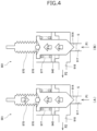
- Fig. 4 and Fig. 5 are diagrams illustrating forces applied to a valve member of an electric valve according to the related art.
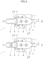
- Fig. 6 and Fig. 7 are diagrams illustrating forces applied to the valve member of the electric valve in Fig. 1 .
- Fig. 4 and Fig. 6 illustrate a forward-flow state where refrigerant flows from a first passage to a second passage. In the forward-flow state, refrigerant pressure P1 in the first passage is higher than refrigerant pressure P2 in the second passage.
- Fig. 5 and Fig. 7 illustrate a reverse-flow state where refrigerant flows from the second passage to the first passage. In the reverse-flow state, refrigerant pressure P2 in the second passage is higher than refrigerant pressure P1 in the first passage.
- Fig. 4A , Fig. 5A , Fig. 6A , and Fig. 7A illustrate a state where a driving shaft pushes a valve member downward.
- Fig. 4B , Fig. 5B , Fig. 6B , and Fig. 7B illustrate a state where the driving shaft is at rest.
- Fig. 7C illustrates a state where the driving shaft moves upward.
- each component is schematically illustrated.
- arrows in thin lines schematically represent refrigerant flow.
- Fig. 4A illustrates the electric valve 901 in the forward-flow state
- a driving shaft 970 pushes a valve member 940 downward by applying force Fc via a ball 976.
- the valve member 940 receives force Fs exerted by a valve opening spring 977 to push the valve member 940 upward and receives force Fr exerted upward by refrigerant.
- valve member 940 can be moved downward to close the valve port 914 when expression (1) below is satisfied in the electric valve 901.
- Fc, Fs, and Fr represent the magnitude of the respective forces.
- a term with a positive sign (+) or no sign represents downward force
- a term with a negative sign (-) represents upward force
- a term with a negative sign (-) represents downward force.
- Fig. 4B illustrates the electric valve 901 in the forward-flow state, with the driving shaft 970 at rest.
- the valve member 940 receives force Fs exerted by the valve opening spring 977 to push the valve member 940 upward and receives force Fr exerted upward by refrigerant. Since force Fs and force Fr are upward forces, expression (2) below is satisfied.
- the driving shaft 970 receives a combined force of force Fs and force Fr while the driving shaft 970 is at rest. The combined force can move the valve member 940 upward to open the valve port 914 when the driving shaft 970 moves upward. 0 ⁇ Fs + Fr
- Fig. 5A illustrates the electric valve 901 in the reverse-flow state
- the driving shaft 970 pushes the valve member 940 downward by applying force Fc via the ball 976.
- the valve member 940 receives force Fs exerted by the valve opening spring 977 to push the valve member 940 upward and receives force Fr exerted downward by refrigerant.
- the valve member 940 can be moved downward to close the valve port 914 when expression (3) below is satisfied in the electric valve 901.
- Fig. 5B illustrates the electric valve 901 in the reverse-flow state, with the driving shaft 970 at rest.
- the valve member 940 receives force Fs exerted by the valve opening spring 977 to push the valve member 940 upward and receives force Fr exerted downward by refrigerant.
- the driving shaft 970 receives a force equal to force Fs minus force Fr while the driving shaft 970 is at rest. This force can move the valve member 940 upward to open the valve port 914 when the driving shaft 970 moves upward.
- Fs ⁇ Fr force exerted downward by refrigerant
- Fig. 6A illustrates the electric valve 1 in the forward-flow state
- the driving shaft 70 pushes the valve member 40 downward by applying force Fc via the ball 76.
- the valve member 40 receives force Fs exerted by the valve opening spring 77 to push the valve member 40 upward and receives force Fr exerted upward by refrigerant.
- the valve member 40 can be moved downward to close the valve port 14 when expression (1) above is satisfied in the electric valve 1.
- Fig. 6B illustrates the electric valve 1 in the forward-flow state, with the driving shaft 70 at rest.
- the valve member 40 receives force Fs exerted by the valve opening spring 77 to push the valve member 40 upward and receives force Fr exerted upward by refrigerant. Since force Fs and force Fr are upward forces, expression (2) above is satisfied.
- the driving shaft 70 receives a combined force of force Fs and force Fr while the driving shaft 70 is at rest. The combined force can move the valve member 40 upward to open the valve port 14 when the driving shaft 70 moves upward.
- Fig. 7A illustrates the electric valve 1 in the reverse-flow state
- the driving shaft 70 pushes the valve member 40 downward by applying force Fc via the ball 76.
- the valve member 40 receives force Fs exerted by the valve opening spring 77 to push the valve member 40 upward and receives force Fr exerted downward by refrigerant.
- the valve member 40 can be moved downward to close the valve port 14 when expression (3) above is satisfied in the electric valve 1.
- Fig. 7B illustrates the electric valve 1 in the reverse-flow state, with the driving shaft 70 at rest.
- the valve member 40 receives force Fs exerted by the valve opening spring 77 to push the valve member 40 upward and receives force Fr exerted downward by refrigerant.
- the driving shaft 70 receives a force equal to force Fs minus force Fr while the driving shaft 70 is at rest. This force can move the valve member 40 upward to open the valve port 14 when the driving shaft 70 moves upward.
- the electric valve 1 includes the valve body 10 having the valve port 14, the valve member 40 facing the valve port 14, the rotor 51 rotatable with respect to the valve body 10, and the driving shaft 70 to which the rotation of the rotor 51 is transmitted.
- the driving shaft 70 moves downward (direction toward the valve port 14) or upward (direction away from the valve port 14).
- the driving shaft 70 pushes the valve member 40 when moving downward and pulls the valve member 40 when moving upward.
- the driving shaft 70 is rotatable with respect to the valve member 40. In this configuration, the driving shaft 70 pulls the valve member 40 upward, enabling the valve port 14 to open without relying on the valve opening spring 77.
- the driving shaft 70 is rotatable with respect to the valve member 40, the driving shaft 70 rotates with respect to the valve member 40 when the valve member 40 is in contact with the valve seat 15, inhibiting the valve member 40 from sliding on the valve seat 15. As a result, it is possible that the electric valve 1 has the valve port 14 with a large diameter while ensuring durability.
- the electric valve 1 includes the connecting member 45 mounted on the valve member 40.
- the connecting member 45 includes projections 49.
- the driving shaft 70 includes the projection receiving portion 74 on which the projections 49 hook when the driving shaft 70 moves upward.
- the projections 49 hook on the projection receiving portion 74 and are rotatable with respect to the projection receiving portion 74.
- the valve member 40 and the driving shaft 70 can be connected so that the driving shaft 70 pushes the valve member 40 when moving downward, pulls the valve member 40 when moving upward, and is rotatable with respect to the valve member 40, in a comparatively simple configuration.
- the connecting member 45 may be mounted on the valve member 40 and the valve member 40 may be rotatable with respect to the connecting member 45. In this configuration, for example, the space between the upper end surface 41a of the stem 41 of the valve member 40 and the flat plate portion 43a of the ball receiving portion 43 is slightly larger than the thickness of the base portion 46 of the connecting member 45.
- the connecting member 45 includes the base portion 46 that has a flat plate-like shape and that is mounted on the valve member 40 and the elastic tabs 47 that extend from the peripheral edge of the base portion 46 toward the driving shaft 70 and that is capable of elastically deforming in the direction away from the center of the base portion 46.
- Each of the elastic tabs 47 includes a projection 49 that projects toward the center of the base portion 46.
- the projection receiving portion 74 is disposed at the end (the first end) of the driving shaft 70 on the valve member 40 side. The first end of the driving shaft 70 is surrounded by the elastic tabs 47.
- the projection 49 can hook on the projection receiving portion 74 by elastically deforming the elastic tabs 47 in the direction away from the center of the base portion 46, placing the first end (the third portion 73 and the projection receiving portion 74) of the driving shaft 70 so as to be surrounded by the elastic tabs 47, and restoring the elastic tabs 47.
- the valve member 40 and the driving shaft 70 can be connected by the connecting member 45 in a comparatively simple configuration.
- the connecting member includes the projection
- the driving shaft includes the projection receiving portion
- the connecting member may include the projection receiving portion
- the driving shaft may include the projection.
- the connecting member is mounted on the valve member.
- the connecting member may be mounted on the driving shaft.
- one of the valve member and the connecting member includes the projection
- the other of the valve member and the connecting member includes the projection receiving portion on which the projection hooks when the connecting member moves away from the valve port together with the driving shaft.
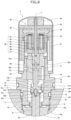
- Fig. 8 is an enlarged sectional view of a part (mainly a valve member, a connecting member, and a driving section) of an electric valve according to the second embodiment of the present invention.
- a stator unit is not illustrated.
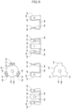
- Fig. 9 is an orthographic projection diagram of a connecting member of the electric valve in Fig. 8 with six views.
- the upper diagram is a plan view
- the lower diagram is a bottom view
- the diagram between the upper and lower diagrams is a front view.
- the left diagram is a left-side view
- the right diagram is a back view
- the diagram adjacent to the right diagram is a right-side view.
- the electric valve 2 has the same (including substantially the same) configuration as that of the electric valve 1 described above except that the electric valve 2 includes, instead of the connecting member 45, a connecting member 145 having a different configuration from the connecting member 45.
- the electric valve 2 includes, instead of the connecting member 45, a connecting member 145 having a different configuration from the connecting member 45.
- the connecting member 145 includes a base portion 146 and elastic tabs 147.
- the base portion 146 has a disc shape.
- the connecting member 145 includes three elastic tabs 147 arranged at regular angular intervals in the circumferential direction of the base portion 146.
- Each of the elastic tabs 147 extends upward from the peripheral edge of the base portion 146.
- Each of the elastic tabs 147 includes a main portion 148 and a projection 149.
- the main portion 148 has a rectangular plate-like shape.
- the main portion 148 is bent in an S-shape.
- the lower end of the main portion 148 is connected to the peripheral edge of the base portion 146.
- the upper end of the main portion 148 points away from the center of the base portion 146.
- the projection 149 has a hemispherical shape.
- the projection 149 projects toward the center of the base portion 146 with respect to the main portion 148.
- the shape of the connecting member 145 has rotational symmetry with the axis of symmetry passing through the center of the base portion 146.
- the connecting member 145 is formed by pressing a metal plate.
- the connecting member 145 is mounted on a valve member 40. Specifically, the lower surface of the base portion 146 of the connecting member 145 is in contact with an upper end surface 41a of a stem 41, and a projecting portion 43b of a ball receiving portion 43 is inserted into a through hole 146a that is provided at the center of the base portion 146. The base portion 146 is held between the upper end surface 41a of the stem 41 and a flat plate portion 43a of the ball receiving portion 43.
- the ball receiving portion 43 also serves as a member for mounting the connecting member 145 on the valve member 40.
- a first end of a driving shaft 70 (a third portion 73 and a projection receiving portion 74) is disposed in a space defined by the elastic tabs 147 of the connecting member 145 and is surrounded by the elastic tabs 147.
- the third portion 73 faces the base portion 146 in an up-and-down direction with a space in between.
- the projection receiving portion 74 is located beneath each projection 149 of the elastic tabs 147, and each projection 149 hooks on the projection receiving portion 74.
- each projection 149 overlaps the projection receiving portion 74 as viewed from above, and each projection 149 is in light contact with the projection receiving portion 74 in the up-and-down direction or is slightly spaced from the projection receiving portion 74 in the up-and-down direction.
- the projections 149 hook on the projection receiving portion 74 when the driving shaft 70 moves upward, and the driving shaft 70 can rotate around an axis L with respect to the connecting member 145.
- the electric valve 2 also has the same (including substantially the same) functions and effects as those of the electric valve 1 described above.
- a circular cylindrical member includes a circular cylindrical member and a substantially circular cylindrical member.
Landscapes
- Engineering & Computer Science (AREA)
- General Engineering & Computer Science (AREA)
- Mechanical Engineering (AREA)
- Physics & Mathematics (AREA)
- Electromagnetism (AREA)
- Electrically Driven Valve-Operating Means (AREA)
Abstract
Description
- The present invention relates to an electric valve.
-
Patent Literature 1 discloses an example of an electric valve according to the related art. The electric valve disclosed inPatent Literature 1 includes a valve chamber, a first passage connected to the valve chamber via a valve port, a second passage connected to the valve chamber, and a valve member facing the valve port in an up-and-down direction. In the electric valve, the valve member is moved in the up-and-down direction along with rotation of a rotor. The electric valve controls the flow rate of refrigerant flowing from the first passage to the second passage and the flow rate of refrigerant flowing from the second passage to the first passage. - In the electric valve, the rotation of the rotor is transmitted to a driving shaft. The driving shaft includes an external thread. The external thread of the driving shaft is screwed into an internal thread of a guide member. When the rotor rotates in one direction, the driving shaft rotates and is moved downward by a screw-feed action. The valve member is pushed downward by the driving shaft and closes the valve port. When the rotor rotates in the other direction, the driving shaft rotates and is moved upward by the screw-feed action. The valve member is pushed upward by a valve opening spring and opens the valve port.
- Patent Literature 1:
Japanese Unexamined Patent Application Publication No. 2018-135908 - In the electric valve described above, when refrigerant pressure in the first passage is higher than refrigerant pressure in the second passage, an upward force is applied to the valve member. The driving shaft pushes the valve member downward against the upward force and against a force exerted by the valve opening spring to push the valve member upward, closing the valve port. Alternatively, when refrigerant pressure in the second passage is higher than refrigerant pressure in the first passage, a downward force is applied to the valve member. The valve opening spring pushes the valve member upward against the downward force, opening the valve port.
- Increasing the diameter of the valve port effectively increases the flow rate of refrigerant flowing in the electric valve. However, since the downward force increases when the diameter of the valve port increases, it is necessary to increase the force exerted by the valve opening spring to push the valve member upward. Hereinafter, the force is referred to as "spring force". Additionally, since the upward force also increases when the diameter of the valve port increases, it is necessary to also increase the force exerted by the driving shaft to push the valve member downward against the upward force and the spring force. Consequently, forces applied to components, such as the driving shaft, increase, accelerating the wear of the components and reducing the durability of the electric valve.
- In the electric valve, the driving shaft can pull the valve member upward to open the valve port by securing the valve member to the driving shaft. Thus, in the electric valve, it is unnecessary to increase the spring force even if the diameter of the valve port increases, and the wear of the components can be suppressed. However, if the valve member is secured to the driving shaft, the valve member rotates together with the driving shaft and slides on a valve seat, which encloses the valve port, in the rotational direction. This accelerates the wear of the valve member and the valve seat, reducing the durability of the electric valve.
- Accordingly, it is an object of the present invention to provide an electric valve capable of having a valve port with a large diameter while ensuring durability.
- To achieve the object described above, an electric valve according to the present invention includes a valve body having a valve port, a valve member facing the valve port, a rotor rotatable with respect to the valve body, and a driving shaft to which rotation of the rotor is transmitted. When the rotation of the rotor is transmitted to the driving shaft, the driving shaft moves toward or away from the valve port. The driving shaft pushes the valve member when moving toward the valve port. The driving shaft pulls the valve member when moving away from the valve port. The driving shaft is rotatable with respect to the valve member.
- In the present invention, preferably, the electric valve further includes a connecting member mounted on the valve member. Preferably, one of the driving shaft and the connecting member includes a projection, and the other of the driving shaft and the connecting member includes a projection receiving portion on which the projection hooks when the driving shaft moves away from the valve port.
- In the present invention, preferably, the projection hooks on the projection receiving portion and is rotatable with respect to the projection receiving portion.
- In the present invention, preferably, the connecting member is mounted on the valve member and the valve member is rotatable with respect to the connecting member.
- In the present invention, preferably, the connecting member includes a base portion that has a flat plate-like shape and that is mounted on the valve member, and elastic tabs that extend from a peripheral edge of the base portion toward the driving shaft and that is capable of elastically deforming in a direction away from a center of the base portion. Preferably, each of the elastic tabs includes the projection that projects toward the center of the base portion. Preferably, the projection receiving portion is disposed at a first end of the driving shaft, and the first end of the driving shaft is surrounded by the elastic tabs.
- In the present invention, preferably, the electric valve further includes a connecting member mounted on the driving shaft. Preferably, one of the valve member and the connecting member includes a projection, and the other of the valve member and the connecting member includes a projection receiving portion on which the projection hooks when the connecting member moves away from the valve port together with the driving shaft.
- According to the present invention, when the rotation of the rotor is transmitted to the driving shaft, the driving shaft moves toward or away from the valve port while rotating. The driving shaft pushes the valve member when moving toward the valve port and pulls the valve member when moving away from the valve port, and the driving shaft is rotatable with respect to the valve member. In this configuration, the driving shaft pulls the valve member away from the valve port, enabling the valve port to open without relying on a valve opening spring that pushes the valve member away from the valve port. Additionally, since the driving shaft is rotatable with respect to the valve member, the driving shaft rotates with respect to the valve member when the valve member is in contact with the valve seat that encloses the valve port, inhibiting the valve member from sliding on the valve seat. As a result, it is possible that the electric valve has a valve port with a large diameter while ensuring durability.
-
- [
Fig. 1] Fig. 1 is a sectional view of an electric valve according to a first embodiment of the present invention. - [
Fig. 2] Fig. 2 is an enlarged sectional view of a part of the electric valve inFig. 1 . - [
Fig. 3] Fig. 3 is an orthographic projection diagram of a connecting member of the electric valve inFig. 1 with six views. - [
Fig. 4] Fig. 4 is a diagram illustrating a force applied to a valve member of an electric valve according to the related art (forward-flow state). - [
Fig. 5] Fig. 5 is a diagram illustrating a force applied to the valve member of the electric valve according to the related art (reverse-flow state). - [
Fig. 6] Fig. 6 is a diagram illustrating a force applied to a valve member of the electric valve inFig. 1 (forward-flow state). - [
Fig. 7] Fig. 7 is a diagram illustrating a force applied to the valve member of the electric valve inFig. 1 (reverse-flow state). - [
Fig. 8] Fig. 8 is an enlarged sectional view of a part of an electric valve according to a second embodiment of the present invention. - [
Fig. 9] Fig. 9 is an orthographic projection diagram of a connecting member of the electric valve inFig. 8 with six views. - An
electric valve 1 according to a first embodiment of the present invention is described below with reference toFig. 1 to Fig. 3 . Theelectric valve 1 according to the embodiment is used, for example, for controlling the flow rate of refrigerant in a refrigeration cycle system of an air conditioner. -
Fig. 1 is a sectional view of an electric valve according to the first embodiment of the present invention.Fig. 2 is an enlarged sectional view of a part (mainly a valve member, a connecting member, and a driving section) of the electric valve inFig. 1 . InFig. 2 , a stator unit is not illustrated.Fig. 3 is an orthographic projection diagram of the connecting member of the electric valve inFig. 1 with six views. InFig. 3 , the upper diagram is a plan view, the lower diagram is a bottom view, and the diagram between the upper and lower diagrams is a front view. InFig. 3 , the left diagram is a left-side view, the right diagram is a back view, and the diagram adjacent to the right diagram is a right-side view. - As illustrated in
Fig. 1 andFig. 2 , theelectric valve 1 according to the embodiment includes avalve body 10, aholder 20, a valve-member supporting member 25, acan 30, avalve member 40, a connectingmember 45, a drivingsection 50, and astator unit 80. - The
valve body 10 has a rectangular parallelepiped shape. Thevalve body 10 includes avalve chamber 13 and avalve port 14 connected to thevalve chamber 13. Thevalve port 14 is enclosed by avalve seat 15. Thevalve body 10 includes afirst passage 17 and asecond passage 18. Thefirst passage 17 includes a first end that is connected to thevalve chamber 13 via thevalve port 14 and a second end that is open on aright surface 10a of thevalve body 10. Thesecond passage 18 includes a first end that is connected to thevalve chamber 13 and a second end that is open on aleft surface 10b of thevalve body 10. Thevalve body 10 has a mountinghole 19. The mountinghole 19 is located in anupper surface 10c of thevalve body 10. The mountinghole 19 includes an inner circumferential surface on which an internal thread is formed. Thevalve chamber 13 is open to abottom surface 19a of the mountinghole 19. - The
holder 20 has a circular cylindrical shape. Theholder 20 includes an outer circumferential surface on which an external thread is formed. The external thread is disposed in the lower part of the outer circumferential surface. The external thread of theholder 20 is screwed into the internal thread of the mountinghole 19 of thevalve body 10. Theholder 20 is mounted on thevalve body 10 by a screw structure. - The valve-
member supporting member 25 has a circular cylindrical shape. The valve-member supporting member 25 is disposed inside the mountinghole 19 and interposed between thevalve body 10 and theholder 20. The valve-member supporting member 25 includes a lower portion press-fitted into thevalve chamber 13. The valve-member supporting member 25 has an outer circumferential surface on which an annularflat surface 25a facing downward is formed. The annularflat surface 25a is in contact with thebottom surface 19a of the mountinghole 19. The valve-member supporting member 25 supports thevalve member 40 to be movable in an up-and-down direction (a direction of an axis L) . - The
can 30 has a circular cylindrical shape. Thecan 30 is closed at the upper end and is open at the lower end. The lower end of thecan 30 is bonded to the outer peripheral edge of ajoint member 35 having a circular annular plate-like shape. Theholder 20 includes anupper portion 20a disposed inside thejoint member 35. The inner peripheral edge of thejoint member 35 is bonded to theholder 20. Thecan 30 is secured to thevalve body 10 via thejoint member 35 and theholder 20. - The
valve member 40 includes astem 41, avalve portion 42, and aball receiving portion 43. Thestem 41 has a circular columnar shape. Thestem 41 is disposed inside the valve-member supporting member 25. Thestem 41 is supported by the valve-member supporting member 25 and can move in the up-and-down direction. Thevalve portion 42 is connected to the lower end of thestem 41. Thevalve portion 42 has a circular annular shape. Thevalve portion 42 projects radially outward from the outer circumferential surface of thestem 41. Thevalve portion 42 faces thevalve port 14 in the up-and-down direction. Theball receiving portion 43 includes aflat plate portion 43a having a circular shape and a projectingportion 43b connected to the lower surface of theflat plate portion 43a. Theflat plate portion 43a includes an upper surface on which a recess having a conical shape is formed. The projectingportion 43b is fitted into ahole 41b provided on anupper end surface 41a of thestem 41. The projectingportion 43b is secured to thestem 41. Thevalve portion 42 moving toward and away from thevalve port 14 causes thevalve member 40 to change the opening area of thevalve port 14 in a stepless (including a substantially stepless) manner. The minimum area of thevalve member 40 is zero (i.e., a state where thevalve port 14 is closed). The minimum area of thevalve port 14 may be greater than zero (i.e., a state where thevalve port 14 is slightly open). - As illustrated in
Fig. 3 , the connectingmember 45 includes abase portion 46 andelastic tabs 47. Thebase portion 46 has a disc shape. In the present embodiment, the connectingmember 45 includes threeelastic tabs 47 arranged at regular angular intervals in the circumferential direction of thebase portion 46. Each of theelastic tabs 47 extends upward from the peripheral edge of thebase portion 46. Each of theelastic tabs 47 includes amain portion 48 and aprojection 49. Themain portion 48 has a rectangular frame shape. Themain portion 48 is at a right angle to thebase portion 46. The lower side of themain portion 48 is connected to the peripheral edge of thebase portion 46. Theprojection 49 has a plate-like shape with a small width and extends downward from the upper side of themain portion 48. Theprojection 49 is bent in an S-shape. The lower end of theprojection 49 is disposed close to the center of thebase portion 46 with respect to themain portion 48. The shape of the connectingmember 45 has rotational symmetry with the axis of symmetry passing through the center of thebase portion 46. The connectingmember 45 is formed by pressing a metal plate. - The connecting
member 45 is mounted on thevalve member 40. Specifically, the lower surface of thebase portion 46 of the connectingmember 45 is in contact with theupper end surface 41a of thestem 41, and the projectingportion 43b of theball receiving portion 43 is inserted into a throughhole 46a that is provided at the center of thebase portion 46. Thebase portion 46 is held between theupper end surface 41a of thestem 41 and theflat plate portion 43a of theball receiving portion 43. Theball receiving portion 43 also serves as a member for mounting the connectingmember 45 on thevalve member 40. The connectingmember 45 may be bonded to thevalve member 40 by adhesive and the like. - The driving
section 50 moves thevalve member 40 in the up-and-down direction. The drivingsection 50 includes arotor 51, apermanent magnet 55, aplanetary gear mechanism 60, aguide member 68, a drivingshaft 70, aball 76, and avalve opening spring 77. - The
rotor 51 has a circular cylindrical shape. Therotor 51 has an outer diameter smaller than the inner diameter of thecan 30. Therotor 51 is rotatably disposed inside thecan 30. Therotor 51 includes an upper end to which a connectingplate 52 is bonded. The connectingplate 52 has a circular shape and closes the upper end of therotor 51. Arotor shaft 53 extends through the center of the connectingplate 52. Therotor 51 is connected to therotor shaft 53 via the connectingplate 52. Therotor shaft 53 rotates together with therotor 51. - The
rotor 51 includes North (N) poles and South (S) poles. The N and S poles extend in the up-and-down direction. The N and S poles are alternately arranged in the circumferential direction on the outer circumferential surface of therotor 51. - The
permanent magnet 55 is located inside thecan 30 and above therotor 51. Thepermanent magnet 55 has a disc shape. Thepermanent magnet 55 is secured to the upper end of therotor shaft 53. Thepermanent magnet 55 is disposed coaxially with therotor 51 and rotates together with therotor 51. Amagnetic shielding member 56 having a disc shape is disposed between therotor 51 and thepermanent magnet 55. Themagnetic shielding member 56 is made of soft magnetic material with relatively high permeability, such as silicon iron or similar materials. Themagnetic shielding member 56 is secured to therotor shaft 53. Themagnetic shielding member 56 absorbs magnetic flux generated by therotor 51. Themagnetic shielding member 56 inhibits the magnetic field generated by thepermanent magnet 55 from being distorted by the magnetic field generated by therotor 51. - The
permanent magnet 55 includes an N pole and an S pole. Thepermanent magnet 55 includes two parts divided by its diameter, with the N pole disposed in one of the two parts, and the S pole disposed in the other. - The
planetary gear mechanism 60 is disposed inside therotor 51. Theplanetary gear mechanism 60 includes agear case 61, a fixed ring gear 62, asun gear 63,planetary gears 64, acarrier 65, anoutput gear 66, and anoutput shaft 67. Thegear case 61 has a circular cylindrical shape. Thegear case 61 includes a lower end that is bonded to and coaxially with theupper portion 20a of theholder 20. The fixed ring gear 62 is an internal gear. The fixed ring gear 62 is fixed to the upper end of thegear case 61. Thesun gear 63 is disposed coaxially with the connectingplate 52. Thesun gear 63 is integrated with the connectingplate 52. Therotor shaft 53 extends through thesun gear 63. Thesun gear 63 rotates together with therotor 51 and the connectingplate 52. Theplanetary gears 64 are interposed between the fixed ring gear 62 and thesun gear 63. Thecarrier 65 has a disc shape. Therotor shaft 53 extends through the center of thecarrier 65. Thecarrier 65 can rotate around therotor shaft 53, which serves as the rotational axis. Thecarrier 65 supports theplanetary gears 64 to be rotatable. Theoutput gear 66 has a circular cylindrical shape with a bottom. Theoutput gear 66 is an internal gear. Theplanetary gears 64 are interposed between theoutput gear 66 and thesun gear 63. Theoutput shaft 67 has a circular columnar shape. Theoutput shaft 67 has an upper portion that is press-fitted into a hole formed in the bottom of theoutput gear 66. Theoutput shaft 67 has a lower portion in which aslit 67a extending in the up-and-down direction is formed. The rotational speed of thesun gear 63 is reduced by the fixed ring gear 62, theplanetary gears 64, thecarrier 65, and theoutput gear 66, and the rotation is transmitted to theoutput shaft 67. - The
guide member 68 has a circular cylindrical shape. Theguide member 68 is disposed inside theupper portion 20a of theholder 20. Theguide member 68 includes an inner circumferential surface on which aninternal thread 68c is formed. Theinternal thread 68c is disposed in the lower part of the inner circumferential surface. Theoutput shaft 67 is disposed inside theguide member 68. Theguide member 68 supports theoutput shaft 67 to be rotatable. - The driving
shaft 70 is formed, for example, by cutting a metal pole having a circular columnar shape. The drivingshaft 70 includes afirst portion 71, asecond portion 72, athird portion 73, and aprojection receiving portion 74. - The
first portion 71 has a rectangular flat plate-like shape. Thefirst portion 71 has a thickness slightly smaller than the width of theslit 67a of theoutput shaft 67. Thefirst portion 71 is disposed inside theslit 67a of theoutput shaft 67 and can move in the up-and-down direction. Theslit 67a and thefirst portion 71 enable the drivingshaft 70 to move in the up-and-down direction with respect to theoutput shaft 67 while transmitting the rotation of theoutput shaft 67 to the drivingshaft 70. - The
second portion 72 has a circular columnar shape. Thesecond portion 72 is connected to the lower end of thefirst portion 71. Thesecond portion 72 includes an outer circumferential surface on which anexternal thread 72c is formed. Theexternal thread 72c is screwed into theinternal thread 68c of theguide member 68. Theguide member 68 may include an external thread, and the drivingshaft 70 may include an internal thread. - The
third portion 73 has a disc shape. Thethird portion 73 is connected to and coaxially with the lower end of thesecond portion 72. Thethird portion 73 has an outer diameter larger than the outer diameter of thesecond portion 72. Thethird portion 73 includes a lower surface on which a recess having a conical shape is formed, and theball 76 is bonded to thethird portion 73 at the recess. Theball 76 is in contact with theflat plate portion 43a of theball receiving portion 43 at the recess of theflat plate portion 43a. - The
projection receiving portion 74 has a circular annular shape. Theprojection receiving portion 74 projects radially outward from the outer circumferential surface of thethird portion 73. The outer diameter of theprojection receiving portion 74 is smaller than a circle C1 inscribed on each of theelastic tabs 47 of the connectingmember 45 and larger than a circle C2 inscribed on eachprojection 49 of the connecting member 45 (Fig. 3 ). Thethird portion 73 and theprojection receiving portion 74 serve as an end (a first end) of the drivingshaft 70 on thevalve member 40 side. Thethird portion 73 and theprojection receiving portion 74 are disposed in a space defined by theelastic tabs 47 of the connectingmember 45 and are surrounded by theelastic tabs 47. Thethird portion 73 faces thebase portion 46 of the connectingmember 45 in the up-and-down direction with a space in between. Theprojection receiving portion 74 is located beneath eachprojection 49 of theelastic tabs 47, and eachprojection 49 hooks on theprojection receiving portion 74. Specifically, eachprojection 49 overlaps theprojection receiving portion 74 as viewed from above, and the lower end of eachprojection 49 is in light contact with theprojection receiving portion 74 in the up-and-down direction or is slightly spaced from theprojection receiving portion 74 in the up-and-down direction. In this configuration, eachprojection 49 hooks on theprojection receiving portion 74 and is rotatable with respect to theprojection receiving portion 74. As a result, theprojections 49 hook on theprojection receiving portion 74 when the drivingshaft 70 moves upward, and the drivingshaft 70 can rotate around the axis L with respect to the connectingmember 45. - The
valve opening spring 77 is disposed between the valve-member supporting member 25 and thebase portion 46 of the connectingmember 45. Thevalve opening spring 77 is a compression coil spring. Thevalve opening spring 77 pushes thevalve member 40 upward via the connectingmember 45. Thevalve opening spring 77 may be omitted in theelectric valve 1. - The
stator unit 80 includes acase 81, astator 82, and acircuit board 83. Thecase 81 is made of synthetic resin. Thecase 81 has a box shape. Thecase 81 houses thestator 82 and thecircuit board 83. Thestator 82 and thecircuit board 83 is secured to thecase 81 by screws. Thestator 82 has a circular cylindrical shape. Thecan 30 is disposed inside thestator 82. Thestator 82 and therotor 51 are members of a stepping motor. - Electronic components including an
angle sensor 84 are mounted on thecircuit board 83. Theangle sensor 84 is a magnetic angle sensor. Theangle sensor 84 is mounted on the lower surface of thecircuit board 83. Theangle sensor 84 is located above thecan 30. Theangle sensor 84 faces thepermanent magnet 55 in the up-and-down direction with thecan 30 in between. Theangle sensor 84 detects the direction and the magnitude of the magnetic field passing through theangle sensor 84. The rotational angle of thepermanent magnet 55 can be obtained based on electric signals output by theangle sensor 84. - In the
electric valve 1, the respective central axes of thevalve port 14, theholder 20, the valve-member supporting member 25, thecan 30, thevalve member 40, the connecting member 45 (the base portion 46), therotor 51, the connectingplate 52, therotor shaft 53, thepermanent magnet 55, theoutput shaft 67, theguide member 68, the drivingshaft 70, and thestator 82 are aligned with the axis L. - Basic operation of the
electric valve 1 is described below. - In the
electric valve 1, a current is applied to thestator 82, rotating therotor 51 in one direction. The rotation of therotor 51 is transmitted to the drivingshaft 70 via theplanetary gear mechanism 60. When the drivingshaft 70 rotates, a screw-feed action between the drivingshaft 70 and theguide member 68 moves the drivingshaft 70 downward. Thevalve member 40 is pushed downward by the drivingshaft 70 and moved downward, decreasing the opening area of thevalve port 14. Theelectric valve 1 is in a valve-closing state when thevalve member 40 comes into contact with thevalve seat 15 and thevalve port 14 closes. - In the
electric valve 1, a current is applied to thestator 82, rotating therotor 51 in the other direction. The rotation of therotor 51 is transmitted to the drivingshaft 70 via theplanetary gear mechanism 60. When the drivingshaft 70 rotates, the screw-feed action between the drivingshaft 70 and theguide member 68 moves the drivingshaft 70 upward. Thevalve member 40 is pushed upward by thevalve opening spring 77 and moved upward, increasing the opening area of thevalve port 14. Even when thevalve member 40 cannot be moved upward solely by the force of thevalve opening spring 77, theprojections 49 hook on theprojection receiving portion 74 as the drivingshaft 70 moves upward. As a result, both the connectingmember 45 and thevalve member 40 are moved upward. Theelectric valve 1 is in a valve-opening state when thevalve member 40 moves away from the valve seat and thevalve port 14 opens. Theelectric valve 1 is in a full-open state when thevalve member 40 is farthest away from thevalve port 14. - A method for connecting the
valve member 40 and the drivingshaft 70 is described below. Thebase portion 46 of the connectingmember 45 is placed on theupper end surface 41a of thestem 41 of thevalve member 40. The connectingmember 45 is mounted on thevalve member 40 by inserting the projectingportion 43b of theball receiving portion 43 into the throughhole 46a of thebase portion 46 and fitting the projectingportion 43b into thehole 41b of thevalve member 40. The first end (thethird portion 73 and the projection receiving portion 74) of the drivingshaft 70 is inserted inside theelastic tabs 47 of the connectingmember 45, and theprojection receiving portion 74 is brought into contact with eachprojection 49 of theelastic tabs 47. The insertion of the first end of the drivingshaft 70 is progressed, and theelastic tabs 47 are elastically deformed in a direction away from the center of thebase portion 46 by theprojection receiving portion 74 pushing theprojections 49. Then, theelastic tabs 47 are restored when theprojection receiving portion 74 passes over theprojections 49. As a result, theball 76 bonded to the drivingshaft 70 comes into contact with theball receiving portion 43, eachprojection 49 of theelastic tabs 47 hooks on theprojection receiving portion 74, and the connectingmember 45 connects thevalve member 40 and the drivingshaft 70. In assembling theelectric valve 1, the first end of the drivingshaft 70 may be inserted inside the elastic tabs of the connectingmember 45 by operating the stepping motor to move the drivingshaft 70 toward thevalve member 40 by the screw-feed action. - Operation of an
electric valve 901 according to the related art and operation of theelectric valve 1 are described below with reference toFig. 4 to Fig. 7 . -
Fig. 4 andFig. 5 are diagrams illustrating forces applied to a valve member of an electric valve according to the related art.Fig. 6 andFig. 7 are diagrams illustrating forces applied to the valve member of the electric valve inFig. 1 .Fig. 4 andFig. 6 illustrate a forward-flow state where refrigerant flows from a first passage to a second passage. In the forward-flow state, refrigerant pressure P1 in the first passage is higher than refrigerant pressure P2 in the second passage.Fig. 5 andFig. 7 illustrate a reverse-flow state where refrigerant flows from the second passage to the first passage. In the reverse-flow state, refrigerant pressure P2 in the second passage is higher than refrigerant pressure P1 in the first passage.Fig. 4A ,Fig. 5A ,Fig. 6A , andFig. 7A illustrate a state where a driving shaft pushes a valve member downward.Fig. 4B ,Fig. 5B ,Fig. 6B , andFig. 7B illustrate a state where the driving shaft is at rest.Fig. 7C illustrates a state where the driving shaft moves upward. InFig. 4 to Fig. 7 , each component is schematically illustrated. InFig. 4 to Fig. 7 , arrows in thin lines schematically represent refrigerant flow. -
Fig. 4A illustrates theelectric valve 901 in the forward-flow state, and a drivingshaft 970 pushes avalve member 940 downward by applying force Fc via aball 976. Thevalve member 940 receives force Fs exerted by avalve opening spring 977 to push thevalve member 940 upward and receives force Fr exerted upward by refrigerant. In the forward-flow state, the magnitude of force Fr is determined by the differential pressure between refrigerant pressure P1 in afirst passage 917 and refrigerant pressure P2 in asecond passage 918 multiplied by passage area S of a valve port 914 (Fr = (P1 - P2) × S). Thus, thevalve member 940 can be moved downward to close thevalve port 914 when expression (1) below is satisfied in theelectric valve 901. In each expression below, Fc, Fs, and Fr represent the magnitude of the respective forces. On the left side of each expression, a term with a positive sign (+) or no sign represents downward force, and a term with a negative sign (-) represents upward force. On the right side of each expression, a term with a positive sign (+) or no sign represents upward force, and a term with a negative sign (-) represents downward force.
-
Fig. 4B illustrates theelectric valve 901 in the forward-flow state, with the drivingshaft 970 at rest. Thevalve member 940 receives force Fs exerted by thevalve opening spring 977 to push thevalve member 940 upward and receives force Fr exerted upward by refrigerant. Since force Fs and force Fr are upward forces, expression (2) below is satisfied. Thus, in theelectric valve 901, the drivingshaft 970 receives a combined force of force Fs and force Fr while the drivingshaft 970 is at rest. The combined force can move thevalve member 940 upward to open thevalve port 914 when the drivingshaft 970 moves upward.
-
Fig. 5A illustrates theelectric valve 901 in the reverse-flow state, and the drivingshaft 970 pushes thevalve member 940 downward by applying force Fc via theball 976. Thevalve member 940 receives force Fs exerted by thevalve opening spring 977 to push thevalve member 940 upward and receives force Fr exerted downward by refrigerant. In the reverse-flow state, the magnitude of force Fr is determined by the differential pressure between refrigerant pressure P2 in thesecond passage 918 and refrigerant pressure P1 in thefirst passage 917 multiplied by passage area S of the valve port 914 (Fr = (P2 - P1) × S). Thus, thevalve member 940 can be moved downward to close thevalve port 914 when expression (3) below is satisfied in theelectric valve 901.
-
Fig. 5B illustrates theelectric valve 901 in the reverse-flow state, with the drivingshaft 970 at rest. Thevalve member 940 receives force Fs exerted by thevalve opening spring 977 to push thevalve member 940 upward and receives force Fr exerted downward by refrigerant. Thus, when expression (4) below is satisfied in theelectric valve 901, the drivingshaft 970 receives a force equal to force Fs minus force Fr while the drivingshaft 970 is at rest. This force can move thevalve member 940 upward to open thevalve port 914 when the drivingshaft 970 moves upward.
- In the
electric valve 901 in the reverse-flow state, when force Fs exerted by thevalve opening spring 977 to push thevalve member 940 upward is greater than force Fr exerted downward by refrigerant, as represented by expression (4), thevalve opening spring 977 can move thevalve member 940 upward. Since force Fr is proportional to passage area S of thevalve port 914, when the diameter of thevalve port 914 increases, it is necessary that thevalve opening spring 977 be capable of exerting force Fs, which is greater than force Fr, on thevalve member 940. Additionally, when force Fs increases, it is necessary to increase force Fc exerted by the drivingshaft 970 to push thevalve member 940 downward. This increases forces applied to each component. -
Fig. 6A illustrates theelectric valve 1 in the forward-flow state, and the drivingshaft 70 pushes thevalve member 40 downward by applying force Fc via theball 76. Thevalve member 40 receives force Fs exerted by thevalve opening spring 77 to push thevalve member 40 upward and receives force Fr exerted upward by refrigerant. In the forward-flow state, the magnitude of force Fr is determined by the differential pressure between refrigerant pressure P1 in thefirst passage 17 and refrigerant pressure P2 in thesecond passage 18 multiplied by passage area S of the valve port 14 (Fr = (P1 - P2) × S). Thus, thevalve member 40 can be moved downward to close thevalve port 14 when expression (1) above is satisfied in theelectric valve 1. -
Fig. 6B illustrates theelectric valve 1 in the forward-flow state, with the drivingshaft 70 at rest. Thevalve member 40 receives force Fs exerted by thevalve opening spring 77 to push thevalve member 40 upward and receives force Fr exerted upward by refrigerant. Since force Fs and force Fr are upward forces, expression (2) above is satisfied. Thus, in theelectric valve 1, the drivingshaft 70 receives a combined force of force Fs and force Fr while the drivingshaft 70 is at rest. The combined force can move thevalve member 40 upward to open thevalve port 14 when the drivingshaft 70 moves upward. -
Fig. 7A illustrates theelectric valve 1 in the reverse-flow state, and the drivingshaft 70 pushes thevalve member 40 downward by applying force Fc via theball 76. Thevalve member 40 receives force Fs exerted by thevalve opening spring 77 to push thevalve member 40 upward and receives force Fr exerted downward by refrigerant. In the reverse-flow state, the magnitude of force Fr is determined by the differential pressure between refrigerant pressure P2 in thesecond passage 18 and refrigerant pressure P1 in thefirst passage 17 multiplied by passage area S of the valve port 14 (Fr = (P2 - P1) × S) . Thus, thevalve member 40 can be moved downward to close thevalve port 14 when expression (3) above is satisfied in theelectric valve 1. -
Fig. 7B illustrates theelectric valve 1 in the reverse-flow state, with the drivingshaft 70 at rest. Thevalve member 40 receives force Fs exerted by thevalve opening spring 77 to push thevalve member 40 upward and receives force Fr exerted downward by refrigerant. Thus, when expression (4) above is satisfied in theelectric valve 1, the drivingshaft 70 receives a force equal to force Fs minus force Fr while the drivingshaft 70 is at rest. This force can move thevalve member 40 upward to open thevalve port 14 when the drivingshaft 70 moves upward. - Even when expression (4) above is not satisfied in the
electric valve 1 in the reverse-flow state, theprojections 49 hook on theprojection receiving portion 74, as illustrated inFig. 7C , when the drivingshaft 70 moves upward. This applies force Fc exerted by the drivingshaft 70 to pull upward to the connectingmember 45 and thevalve member 40. Thus, thevalve member 40 can be moved upward to open thevalve port 14 when expression (5) below is satisfied and the drivingshaft 70 moves upward. As a result, if the diameter of thevalve port 14 of theelectric valve 1 increases, thevalve port 14 can be opened by increasing force Fc, and it is unnecessary to increase force Fs exerted by thevalve opening spring 77 to push thevalve member 40 upward.
- As described above, the
electric valve 1 includes thevalve body 10 having thevalve port 14, thevalve member 40 facing thevalve port 14, therotor 51 rotatable with respect to thevalve body 10, and the drivingshaft 70 to which the rotation of therotor 51 is transmitted. When the rotation of therotor 51 is transmitted to the drivingshaft 70, the drivingshaft 70 moves downward (direction toward the valve port 14) or upward (direction away from the valve port 14). The drivingshaft 70 pushes thevalve member 40 when moving downward and pulls thevalve member 40 when moving upward. The drivingshaft 70 is rotatable with respect to thevalve member 40. In this configuration, the drivingshaft 70 pulls thevalve member 40 upward, enabling thevalve port 14 to open without relying on thevalve opening spring 77. Additionally, since the drivingshaft 70 is rotatable with respect to thevalve member 40, the drivingshaft 70 rotates with respect to thevalve member 40 when thevalve member 40 is in contact with thevalve seat 15, inhibiting thevalve member 40 from sliding on thevalve seat 15. As a result, it is possible that theelectric valve 1 has thevalve port 14 with a large diameter while ensuring durability. - The
electric valve 1 includes the connectingmember 45 mounted on thevalve member 40. The connectingmember 45 includesprojections 49. The drivingshaft 70 includes theprojection receiving portion 74 on which theprojections 49 hook when the drivingshaft 70 moves upward. Theprojections 49 hook on theprojection receiving portion 74 and are rotatable with respect to theprojection receiving portion 74. In this configuration, thevalve member 40 and the drivingshaft 70 can be connected so that the drivingshaft 70 pushes thevalve member 40 when moving downward, pulls thevalve member 40 when moving upward, and is rotatable with respect to thevalve member 40, in a comparatively simple configuration. The connectingmember 45 may be mounted on thevalve member 40 and thevalve member 40 may be rotatable with respect to the connectingmember 45. In this configuration, for example, the space between theupper end surface 41a of thestem 41 of thevalve member 40 and theflat plate portion 43a of theball receiving portion 43 is slightly larger than the thickness of thebase portion 46 of the connectingmember 45. - The connecting
member 45 includes thebase portion 46 that has a flat plate-like shape and that is mounted on thevalve member 40 and theelastic tabs 47 that extend from the peripheral edge of thebase portion 46 toward the drivingshaft 70 and that is capable of elastically deforming in the direction away from the center of thebase portion 46. Each of theelastic tabs 47 includes aprojection 49 that projects toward the center of thebase portion 46. Theprojection receiving portion 74 is disposed at the end (the first end) of the drivingshaft 70 on thevalve member 40 side. The first end of the drivingshaft 70 is surrounded by theelastic tabs 47. In this configuration, theprojection 49 can hook on theprojection receiving portion 74 by elastically deforming theelastic tabs 47 in the direction away from the center of thebase portion 46, placing the first end (thethird portion 73 and the projection receiving portion 74) of the drivingshaft 70 so as to be surrounded by theelastic tabs 47, and restoring theelastic tabs 47. As a result, thevalve member 40 and the drivingshaft 70 can be connected by the connectingmember 45 in a comparatively simple configuration. - In the
electric valve 1 described above, the connecting member includes the projection, and the driving shaft includes the projection receiving portion. However, the connecting member may include the projection receiving portion, and the driving shaft may include the projection. In theelectric valve 1, the connecting member is mounted on the valve member. However, the connecting member may be mounted on the driving shaft. In this configuration, one of the valve member and the connecting member includes the projection, and the other of the valve member and the connecting member includes the projection receiving portion on which the projection hooks when the connecting member moves away from the valve port together with the driving shaft. - An
electric valve 2 according to a second embodiment of the present invention is described below with reference toFig. 8 andFig. 9 . -
Fig. 8 is an enlarged sectional view of a part (mainly a valve member, a connecting member, and a driving section) of an electric valve according to the second embodiment of the present invention. InFig. 8 , a stator unit is not illustrated.Fig. 9 is an orthographic projection diagram of a connecting member of the electric valve inFig. 8 with six views. InFig. 9 , the upper diagram is a plan view, the lower diagram is a bottom view, and the diagram between the upper and lower diagrams is a front view. InFig. 9 , the left diagram is a left-side view, the right diagram is a back view, and the diagram adjacent to the right diagram is a right-side view. - The
electric valve 2 has the same (including substantially the same) configuration as that of theelectric valve 1 described above except that theelectric valve 2 includes, instead of the connectingmember 45, a connectingmember 145 having a different configuration from the connectingmember 45. Thus, in the description of theelectric valve 2, elements having the same configuration as those of theelectric valve 1 are denoted by the same reference signs as those of theelectric valve 1, and detailed descriptions of these elements are omitted. - The connecting
member 145 includes abase portion 146 andelastic tabs 147. Thebase portion 146 has a disc shape. In the embodiment, the connectingmember 145 includes threeelastic tabs 147 arranged at regular angular intervals in the circumferential direction of thebase portion 146. Each of theelastic tabs 147 extends upward from the peripheral edge of thebase portion 146. Each of theelastic tabs 147 includes amain portion 148 and aprojection 149. Themain portion 148 has a rectangular plate-like shape. Themain portion 148 is bent in an S-shape. The lower end of themain portion 148 is connected to the peripheral edge of thebase portion 146. The upper end of themain portion 148 points away from the center of thebase portion 146. Theprojection 149 has a hemispherical shape. Theprojection 149 projects toward the center of thebase portion 146 with respect to themain portion 148. The shape of the connectingmember 145 has rotational symmetry with the axis of symmetry passing through the center of thebase portion 146. The connectingmember 145 is formed by pressing a metal plate. - The connecting
member 145 is mounted on avalve member 40. Specifically, the lower surface of thebase portion 146 of the connectingmember 145 is in contact with anupper end surface 41a of astem 41, and a projectingportion 43b of aball receiving portion 43 is inserted into a throughhole 146a that is provided at the center of thebase portion 146. Thebase portion 146 is held between theupper end surface 41a of thestem 41 and aflat plate portion 43a of theball receiving portion 43. Theball receiving portion 43 also serves as a member for mounting the connectingmember 145 on thevalve member 40. - A first end of a driving shaft 70 (a
third portion 73 and a projection receiving portion 74) is disposed in a space defined by theelastic tabs 147 of the connectingmember 145 and is surrounded by theelastic tabs 147. Thethird portion 73 faces thebase portion 146 in an up-and-down direction with a space in between. Theprojection receiving portion 74 is located beneath eachprojection 149 of theelastic tabs 147, and eachprojection 149 hooks on theprojection receiving portion 74. Specifically, eachprojection 149 overlaps theprojection receiving portion 74 as viewed from above, and eachprojection 149 is in light contact with theprojection receiving portion 74 in the up-and-down direction or is slightly spaced from theprojection receiving portion 74 in the up-and-down direction. As a result, theprojections 149 hook on theprojection receiving portion 74 when the drivingshaft 70 moves upward, and the drivingshaft 70 can rotate around an axis L with respect to the connectingmember 145. - The
electric valve 2 also has the same (including substantially the same) functions and effects as those of theelectric valve 1 described above. - In this specification, terms indicating shapes, such as "circular cylindrical", "circular columnar", and "rectangular parallelepiped", are also used for members and portions of the members substantially having the shapes indicated by the terms. For example, "a circular cylindrical member" includes a circular cylindrical member and a substantially circular cylindrical member.
- The embodiments of the present invention are described above. The present invention, however, is not limited to configurations of these embodiments. Embodiments obtained by a person skilled in the art appropriately adding, removing, or modifying components according to the embodiments described above, and an embodiment obtained by appropriately combining features of the embodiment are included in the scope of the present invention without departing from the spirit of the present invention. Reference Signs List
- 1,2 ... electric valve, 10 ... valve body, 10a ... right surface, 10b ... left surface, 10c ... upper surface, 13 ... valve chamber, 14 ... valve port, 15 ... valve seat, 17 ... first passage, 18 ... second passage, 19 ... mounting hole, 19a ... bottom surface, 20 ... holder, 20a ... upper portion, 25 ... valve-member supporting member, 25a ... annular flat surface, 30 ... can, 35 ... joint member, 40 ... valve member, 41 ... stem, 41a ... upper end surface, 41b ... hole, 42 ... valve portion, 43 ... ball receiving portion, 43a ... flat plate portion, 43b ... projecting portion, 45 ... connecting member, 46 ... base portion, 46a ... through hole, 47 ... elastic tab, 48 ... main portion, 49 ... projection, 50 ... driving section, 51 ... rotor, 52 ... connecting plate, 53 ... rotor shaft, 55 ... permanent magnet, 56 ... magnetic shielding member, 60 ... planetary gear mechanism, 61 ... gear case, 62 ... fixed ring gear, 63 ... sun gear, 64 ... planetary gear, 65 ... carrier, 66 ... output gear, 67 ... output shaft, 67a ... slit, 68 ... guide member, 68c ... internal thread, 70 ... driving shaft, 71 ... first portion, 72 ... second portion, 72c ... external thread, 73 ... third portion, 74 ... projection receiving portion, 76 ... ball, 77 ... valve opening spring, 80 ... stator unit, 81 ... case, 82 ... stator, 83 ... circuit board, 84 ... angle sensor, 145 ... connecting member, 146 ... base portion, 146a ... through hole, 147 ... elastic tab, 148 ... main portion, 149 ... projection, 901 ... electric valve, 914 ... valve port, 917 ... first passage, 918 ... second passage, 940 ... valve member, 970 ... driving shaft, 977 ... valve opening spring
Claims (6)
- An electric valve comprising:a valve body having a valve port;a valve member facing the valve port;a rotor rotatable with respect to the valve body; anda driving shaft to which rotation of the rotor is transmitted,wherein when the rotation of the rotor is transmitted to the driving shaft, the driving shaft moves toward or away from the valve port, andwherein the driving shaft pushes the valve member when moving toward the valve port,the driving shaft pulls the valve member when moving away from the valve port, andthe driving shaft is rotatable with respect to the valve member.
- The electric valve according to Claim 1, further comprising:a connecting member mounted on the valve member,wherein one of the driving shaft and the connecting member includes a projection, andwherein the other of the driving shaft and the connecting member includes a projection receiving portion on which the projection hooks when the driving shaft moves away from the valve port.
- The electric valve according to Claim 2, wherein the projection hooks on the projection receiving portion and is rotatable with respect to the projection receiving portion.
- The electric valve according to Claim 2, wherein the connecting member is mounted on the valve member and the valve member is rotatable with respect to the connecting member.
- The electric valve according to Claim 2 to Claim 4,wherein the connecting member includes a base portion that has a flat plate-like shape and that is mounted on the valve member, and elastic tabs that extend from a peripheral edge of the base portion toward the driving shaft and that is capable of elastically deforming in a direction away from a center of the base portion,wherein each of the elastic tabs includes the projection that projects toward the center of the base portion,wherein the projection receiving portion is disposed at a first end of the driving shaft, andwherein the first end of the driving shaft is surrounded by the elastic tabs.
- The electric valve according to Claim 1, further comprising:a connecting member mounted on the driving shaft,wherein one of the valve member and the connecting member includes a projection, andwherein the other of the valve member and the connecting member includes a projection receiving portion on which the projection hooks when the connecting member moves away from the valve port together with the driving shaft.
Applications Claiming Priority (2)
| Application Number | Priority Date | Filing Date | Title |
|---|---|---|---|
| JP2021150610A JP7555594B2 (en) | 2021-09-15 | 2021-09-15 | Motor-operated valve |
| PCT/JP2022/029468 WO2023042557A1 (en) | 2021-09-15 | 2022-08-01 | Electric valve |
Publications (2)
| Publication Number | Publication Date |
|---|---|
| EP4403809A1 true EP4403809A1 (en) | 2024-07-24 |
| EP4403809A4 EP4403809A4 (en) | 2025-10-08 |
Family
ID=85602140
Family Applications (1)
| Application Number | Title | Priority Date | Filing Date |
|---|---|---|---|
| EP22869705.8A Pending EP4403809A4 (en) | 2021-09-15 | 2022-08-01 | ELECTRIC VALVE |
Country Status (5)
| Country | Link |
|---|---|
| EP (1) | EP4403809A4 (en) |
| JP (1) | JP7555594B2 (en) |
| KR (2) | KR102766664B1 (en) |
| CN (1) | CN117881917A (en) |
| WO (1) | WO2023042557A1 (en) |
Family Cites Families (16)
| Publication number | Priority date | Publication date | Assignee | Title |
|---|---|---|---|---|
| JPS5151516U (en) * | 1974-10-18 | 1976-04-19 | ||
| JPS62143876U (en) * | 1986-03-06 | 1987-09-10 | ||
| JP3291152B2 (en) * | 1995-02-15 | 2002-06-10 | 株式会社フジキン | Diaphragm valve |
| JP3937029B2 (en) * | 1999-03-26 | 2007-06-27 | 株式会社鷺宮製作所 | Motorized valve |
| JP4383933B2 (en) * | 2004-03-15 | 2009-12-16 | 三菱電機株式会社 | Method for manufacturing output shaft connection structure of electric control valve |
| JP4762018B2 (en) | 2006-03-23 | 2011-08-31 | 株式会社不二工機 | Motorized valve |
| JP2008101765A (en) * | 2006-09-20 | 2008-05-01 | Fuji Koki Corp | Motorized valve |
| JP2009257523A (en) * | 2008-04-18 | 2009-11-05 | Mitsubishi Electric Corp | Solenoid valve |
| JP5947505B2 (en) * | 2011-08-30 | 2016-07-06 | 株式会社堀場エステック | Fluid control valve |
| CN107076329B (en) * | 2016-06-23 | 2019-04-23 | 太平洋工业株式会社 | Electric valve |
| JP6741611B2 (en) | 2017-02-20 | 2020-08-19 | 株式会社不二工機 | Motorized valve |
| JP6657363B2 (en) | 2018-01-25 | 2020-03-04 | 株式会社不二工機 | Flow control valve |
| JP7154018B2 (en) * | 2018-03-02 | 2022-10-17 | 株式会社堀場エステック | Fluid control valve and fluid control device |
| EP3671073A1 (en) * | 2018-12-20 | 2020-06-24 | Danfoss A/S | Electric expansion valve |
| DE102020124870A1 (en) * | 2019-12-04 | 2021-06-10 | ECO Holding 1 GmbH | Expansion valve |
| JP7503819B2 (en) * | 2020-03-23 | 2024-06-21 | 株式会社不二工機 | Motor-operated valve |
-
2021
- 2021-09-15 JP JP2021150610A patent/JP7555594B2/en active Active
-
2022
- 2022-08-01 WO PCT/JP2022/029468 patent/WO2023042557A1/en not_active Ceased
- 2022-08-01 KR KR1020237029578A patent/KR102766664B1/en active Active
- 2022-08-01 CN CN202280014042.3A patent/CN117881917A/en active Pending
- 2022-08-01 EP EP22869705.8A patent/EP4403809A4/en active Pending
- 2022-08-01 KR KR1020257003783A patent/KR20250025497A/en active Pending
Also Published As
| Publication number | Publication date |
|---|---|
| EP4403809A4 (en) | 2025-10-08 |
| CN117881917A (en) | 2024-04-12 |
| JP2023043092A (en) | 2023-03-28 |
| KR20230137994A (en) | 2023-10-05 |
| KR20250025497A (en) | 2025-02-21 |
| JP7555594B2 (en) | 2024-09-25 |
| WO2023042557A1 (en) | 2023-03-23 |
| KR102766664B1 (en) | 2025-02-14 |
Similar Documents
| Publication | Publication Date | Title |
|---|---|---|
| EP0978931A1 (en) | Control valve apparatus | |
| EP4089306A1 (en) | Electric-operated valve | |
| AU2009202560A1 (en) | Electromagnetic transducer with reduced sensitivity to external magnetic fields, and method of improving hearing or sensing vibrations using such a transducer | |
| EP4403809A1 (en) | Electric valve | |
| JP2004312821A (en) | Stepping motor and flow control valve having same | |
| JP2008261698A (en) | Indicating instrument device | |
| US4885730A (en) | Analog electronic timepiece using an intermittent driving signal | |
| JP2001027362A (en) | Flow control device for fluid | |
| EP4729815A1 (en) | Electric valve | |
| CN110375102B (en) | Drain valve control device | |
| EP4675138A1 (en) | Motor operated valve | |
| CN109839812A (en) | Magnetic devices for making axis placed in the middle in watch and clock movement | |
| JP2011085180A (en) | Variable speed electromagnetic clutch | |
| JP4308082B2 (en) | Drive unit | |
| JP2001295957A (en) | Expansion valve | |
| KR100188640B1 (en) | Reed switch drive device and its attachment structure | |
| EP4435304A1 (en) | Electric valve | |
| JPH0721886A (en) | Mounting structure of reed switch | |
| JP2004158076A (en) | Clamp mechanism of magnetic disk | |
| JP7050634B2 (en) | clock | |
| JPH10254022A (en) | Electric diaphragm device | |
| JPH09331664A (en) | Rotary electromagnetic actuator | |
| EP0342705A2 (en) | Electronic watch | |
| KR20260002992A (en) | Electric valves and valve devices | |
| EP4656919A1 (en) | Electric valve and electric valve unit |
Legal Events
| Date | Code | Title | Description |
|---|---|---|---|
| STAA | Information on the status of an ep patent application or granted ep patent |
Free format text: STATUS: THE INTERNATIONAL PUBLICATION HAS BEEN MADE |
|
| PUAI | Public reference made under article 153(3) epc to a published international application that has entered the european phase |
Free format text: ORIGINAL CODE: 0009012 |
|
| STAA | Information on the status of an ep patent application or granted ep patent |
Free format text: STATUS: REQUEST FOR EXAMINATION WAS MADE |
|
| 17P | Request for examination filed |
Effective date: 20240319 |
|
| AK | Designated contracting states |
Kind code of ref document: A1 Designated state(s): AL AT BE BG CH CY CZ DE DK EE ES FI FR GB GR HR HU IE IS IT LI LT LU LV MC MK MT NL NO PL PT RO RS SE SI SK SM TR |
|
| DAV | Request for validation of the european patent (deleted) | ||
| DAX | Request for extension of the european patent (deleted) | ||
| A4 | Supplementary search report drawn up and despatched |
Effective date: 20250908 |
|
| RIC1 | Information provided on ipc code assigned before grant |
Ipc: F16K 31/04 20060101AFI20250902BHEP Ipc: F16K 31/50 20060101ALI20250902BHEP Ipc: F16K 27/02 20060101ALI20250902BHEP |