EP4403797A1 - Transmission et utilisation d'une transmission - Google Patents
Transmission et utilisation d'une transmission Download PDFInfo
- Publication number
- EP4403797A1 EP4403797A1 EP24153174.8A EP24153174A EP4403797A1 EP 4403797 A1 EP4403797 A1 EP 4403797A1 EP 24153174 A EP24153174 A EP 24153174A EP 4403797 A1 EP4403797 A1 EP 4403797A1
- Authority
- EP
- European Patent Office
- Prior art keywords
- bearing
- rolling elements
- axial
- gearbox
- row
- Prior art date
- Legal status (The legal status is an assumption and is not a legal conclusion. Google has not performed a legal analysis and makes no representation as to the accuracy of the status listed.)
- Pending
Links
Images


Classifications
-
- F—MECHANICAL ENGINEERING; LIGHTING; HEATING; WEAPONS; BLASTING
- F16—ENGINEERING ELEMENTS AND UNITS; GENERAL MEASURES FOR PRODUCING AND MAINTAINING EFFECTIVE FUNCTIONING OF MACHINES OR INSTALLATIONS; THERMAL INSULATION IN GENERAL
- F16H—GEARING
- F16H57/00—General details of gearing
- F16H57/02—Gearboxes; Mounting gearing therein
-
- F—MECHANICAL ENGINEERING; LIGHTING; HEATING; WEAPONS; BLASTING
- F16—ENGINEERING ELEMENTS AND UNITS; GENERAL MEASURES FOR PRODUCING AND MAINTAINING EFFECTIVE FUNCTIONING OF MACHINES OR INSTALLATIONS; THERMAL INSULATION IN GENERAL
- F16H—GEARING
- F16H49/00—Other gearings
- F16H49/001—Wave gearings, e.g. harmonic drive transmissions
-
- F—MECHANICAL ENGINEERING; LIGHTING; HEATING; WEAPONS; BLASTING
- F16—ENGINEERING ELEMENTS AND UNITS; GENERAL MEASURES FOR PRODUCING AND MAINTAINING EFFECTIVE FUNCTIONING OF MACHINES OR INSTALLATIONS; THERMAL INSULATION IN GENERAL
- F16C—SHAFTS; FLEXIBLE SHAFTS; ELEMENTS OR CRANKSHAFT MECHANISMS; ROTARY BODIES OTHER THAN GEARING ELEMENTS; BEARINGS
- F16C19/00—Bearings with rolling contact, for exclusively rotary movement
- F16C19/22—Bearings with rolling contact, for exclusively rotary movement with bearing rollers essentially of the same size in one or more circular rows, e.g. needle bearings
- F16C19/30—Bearings with rolling contact, for exclusively rotary movement with bearing rollers essentially of the same size in one or more circular rows, e.g. needle bearings for axial load mainly
- F16C19/305—Bearings with rolling contact, for exclusively rotary movement with bearing rollers essentially of the same size in one or more circular rows, e.g. needle bearings for axial load mainly consisting of rollers held in a cage
-
- F—MECHANICAL ENGINEERING; LIGHTING; HEATING; WEAPONS; BLASTING
- F16—ENGINEERING ELEMENTS AND UNITS; GENERAL MEASURES FOR PRODUCING AND MAINTAINING EFFECTIVE FUNCTIONING OF MACHINES OR INSTALLATIONS; THERMAL INSULATION IN GENERAL
- F16C—SHAFTS; FLEXIBLE SHAFTS; ELEMENTS OR CRANKSHAFT MECHANISMS; ROTARY BODIES OTHER THAN GEARING ELEMENTS; BEARINGS
- F16C19/00—Bearings with rolling contact, for exclusively rotary movement
- F16C19/22—Bearings with rolling contact, for exclusively rotary movement with bearing rollers essentially of the same size in one or more circular rows, e.g. needle bearings
- F16C19/34—Bearings with rolling contact, for exclusively rotary movement with bearing rollers essentially of the same size in one or more circular rows, e.g. needle bearings for both radial and axial load
- F16C19/36—Bearings with rolling contact, for exclusively rotary movement with bearing rollers essentially of the same size in one or more circular rows, e.g. needle bearings for both radial and axial load with a single row of rollers
- F16C19/361—Bearings with rolling contact, for exclusively rotary movement with bearing rollers essentially of the same size in one or more circular rows, e.g. needle bearings for both radial and axial load with a single row of rollers with cylindrical rollers
- F16C19/362—Bearings with rolling contact, for exclusively rotary movement with bearing rollers essentially of the same size in one or more circular rows, e.g. needle bearings for both radial and axial load with a single row of rollers with cylindrical rollers the rollers being crossed within the single row
-
- F—MECHANICAL ENGINEERING; LIGHTING; HEATING; WEAPONS; BLASTING
- F16—ENGINEERING ELEMENTS AND UNITS; GENERAL MEASURES FOR PRODUCING AND MAINTAINING EFFECTIVE FUNCTIONING OF MACHINES OR INSTALLATIONS; THERMAL INSULATION IN GENERAL
- F16C—SHAFTS; FLEXIBLE SHAFTS; ELEMENTS OR CRANKSHAFT MECHANISMS; ROTARY BODIES OTHER THAN GEARING ELEMENTS; BEARINGS
- F16C19/00—Bearings with rolling contact, for exclusively rotary movement
- F16C19/22—Bearings with rolling contact, for exclusively rotary movement with bearing rollers essentially of the same size in one or more circular rows, e.g. needle bearings
- F16C19/34—Bearings with rolling contact, for exclusively rotary movement with bearing rollers essentially of the same size in one or more circular rows, e.g. needle bearings for both radial and axial load
- F16C19/38—Bearings with rolling contact, for exclusively rotary movement with bearing rollers essentially of the same size in one or more circular rows, e.g. needle bearings for both radial and axial load with two or more rows of rollers
- F16C19/381—Bearings with rolling contact, for exclusively rotary movement with bearing rollers essentially of the same size in one or more circular rows, e.g. needle bearings for both radial and axial load with two or more rows of rollers with at least one row for radial load in combination with at least one row for axial load
-
- F—MECHANICAL ENGINEERING; LIGHTING; HEATING; WEAPONS; BLASTING
- F16—ENGINEERING ELEMENTS AND UNITS; GENERAL MEASURES FOR PRODUCING AND MAINTAINING EFFECTIVE FUNCTIONING OF MACHINES OR INSTALLATIONS; THERMAL INSULATION IN GENERAL
- F16C—SHAFTS; FLEXIBLE SHAFTS; ELEMENTS OR CRANKSHAFT MECHANISMS; ROTARY BODIES OTHER THAN GEARING ELEMENTS; BEARINGS
- F16C33/00—Parts of bearings; Special methods for making bearings or parts thereof
- F16C33/30—Parts of ball or roller bearings
- F16C33/58—Raceways; Race rings
- F16C33/581—Raceways; Race rings integral with other parts, e.g. with housings or machine elements such as shafts or gear wheels
-
- F—MECHANICAL ENGINEERING; LIGHTING; HEATING; WEAPONS; BLASTING
- F16—ENGINEERING ELEMENTS AND UNITS; GENERAL MEASURES FOR PRODUCING AND MAINTAINING EFFECTIVE FUNCTIONING OF MACHINES OR INSTALLATIONS; THERMAL INSULATION IN GENERAL
- F16H—GEARING
- F16H25/00—Gearings comprising primarily only cams, cam-followers and screw-and-nut mechanisms
- F16H25/04—Gearings comprising primarily only cams, cam-followers and screw-and-nut mechanisms for conveying rotary motion
- F16H25/06—Gearings comprising primarily only cams, cam-followers and screw-and-nut mechanisms for conveying rotary motion with intermediate members guided along tracks on both rotary members
-
- F—MECHANICAL ENGINEERING; LIGHTING; HEATING; WEAPONS; BLASTING
- F16—ENGINEERING ELEMENTS AND UNITS; GENERAL MEASURES FOR PRODUCING AND MAINTAINING EFFECTIVE FUNCTIONING OF MACHINES OR INSTALLATIONS; THERMAL INSULATION IN GENERAL
- F16H—GEARING
- F16H57/00—General details of gearing
- F16H57/02—Gearboxes; Mounting gearing therein
- F16H57/021—Shaft support structures, e.g. partition walls, bearing eyes, casing walls or covers with bearings
-
- F—MECHANICAL ENGINEERING; LIGHTING; HEATING; WEAPONS; BLASTING
- F16—ENGINEERING ELEMENTS AND UNITS; GENERAL MEASURES FOR PRODUCING AND MAINTAINING EFFECTIVE FUNCTIONING OF MACHINES OR INSTALLATIONS; THERMAL INSULATION IN GENERAL
- F16H—GEARING
- F16H57/00—General details of gearing
- F16H57/02—Gearboxes; Mounting gearing therein
- F16H57/023—Mounting or installation of gears or shafts in the gearboxes, e.g. methods or means for assembly
-
- F—MECHANICAL ENGINEERING; LIGHTING; HEATING; WEAPONS; BLASTING
- F16—ENGINEERING ELEMENTS AND UNITS; GENERAL MEASURES FOR PRODUCING AND MAINTAINING EFFECTIVE FUNCTIONING OF MACHINES OR INSTALLATIONS; THERMAL INSULATION IN GENERAL
- F16H—GEARING
- F16H57/00—General details of gearing
- F16H57/08—General details of gearing of gearings with members having orbital motion
-
- F—MECHANICAL ENGINEERING; LIGHTING; HEATING; WEAPONS; BLASTING
- F16—ENGINEERING ELEMENTS AND UNITS; GENERAL MEASURES FOR PRODUCING AND MAINTAINING EFFECTIVE FUNCTIONING OF MACHINES OR INSTALLATIONS; THERMAL INSULATION IN GENERAL
- F16H—GEARING
- F16H57/00—General details of gearing
- F16H57/08—General details of gearing of gearings with members having orbital motion
- F16H57/082—Planet carriers
-
- F—MECHANICAL ENGINEERING; LIGHTING; HEATING; WEAPONS; BLASTING
- F16—ENGINEERING ELEMENTS AND UNITS; GENERAL MEASURES FOR PRODUCING AND MAINTAINING EFFECTIVE FUNCTIONING OF MACHINES OR INSTALLATIONS; THERMAL INSULATION IN GENERAL
- F16C—SHAFTS; FLEXIBLE SHAFTS; ELEMENTS OR CRANKSHAFT MECHANISMS; ROTARY BODIES OTHER THAN GEARING ELEMENTS; BEARINGS
- F16C2361/00—Apparatus or articles in engineering in general
- F16C2361/61—Toothed gear systems, e.g. support of pinion shafts
-
- F—MECHANICAL ENGINEERING; LIGHTING; HEATING; WEAPONS; BLASTING
- F16—ENGINEERING ELEMENTS AND UNITS; GENERAL MEASURES FOR PRODUCING AND MAINTAINING EFFECTIVE FUNCTIONING OF MACHINES OR INSTALLATIONS; THERMAL INSULATION IN GENERAL
- F16H—GEARING
- F16H57/00—General details of gearing
- F16H57/02—Gearboxes; Mounting gearing therein
- F16H2057/02039—Gearboxes for particular applications
- F16H2057/02069—Gearboxes for particular applications for industrial applications
-
- F—MECHANICAL ENGINEERING; LIGHTING; HEATING; WEAPONS; BLASTING
- F16—ENGINEERING ELEMENTS AND UNITS; GENERAL MEASURES FOR PRODUCING AND MAINTAINING EFFECTIVE FUNCTIONING OF MACHINES OR INSTALLATIONS; THERMAL INSULATION IN GENERAL
- F16H—GEARING
- F16H57/00—General details of gearing
- F16H57/02—Gearboxes; Mounting gearing therein
- F16H2057/02039—Gearboxes for particular applications
- F16H2057/02078—Gearboxes for particular applications for wind turbines
-
- F—MECHANICAL ENGINEERING; LIGHTING; HEATING; WEAPONS; BLASTING
- F16—ENGINEERING ELEMENTS AND UNITS; GENERAL MEASURES FOR PRODUCING AND MAINTAINING EFFECTIVE FUNCTIONING OF MACHINES OR INSTALLATIONS; THERMAL INSULATION IN GENERAL
- F16H—GEARING
- F16H57/00—General details of gearing
- F16H57/02—Gearboxes; Mounting gearing therein
- F16H2057/02086—Measures for reducing size of gearbox, e.g. for creating a more compact transmission casing
-
- F—MECHANICAL ENGINEERING; LIGHTING; HEATING; WEAPONS; BLASTING
- F16—ENGINEERING ELEMENTS AND UNITS; GENERAL MEASURES FOR PRODUCING AND MAINTAINING EFFECTIVE FUNCTIONING OF MACHINES OR INSTALLATIONS; THERMAL INSULATION IN GENERAL
- F16H—GEARING
- F16H57/00—General details of gearing
- F16H57/08—General details of gearing of gearings with members having orbital motion
- F16H2057/085—Bearings for orbital gears
Definitions
- the invention relates to a transmission and a use of a transmission.
- Gears are known from the prior art which comprise teeth which are mounted radially displaceably in a tooth carrier.
- Drive elements with a profile such as cam disks, are used to drive the teeth.
- the teeth engage in a toothing, so that a relative movement occurs between the tooth carrier with the teeth and the toothing.
- the relative movement between the toothing and the teeth is at least one order of magnitude smaller than the movement of the drive element with the profile. In this way, high gear ratios can be achieved; an example of such a gear is shown in the EN 10 2015 119 582 A1 published.
- gearboxes may not meet the compactness requirements for limited installation space. Furthermore, it may be desirable to improve concentricity or axial runout for some applications.
- the object of the invention is to provide a gear unit which is improved compared to gear units known from the prior art, whereby in particular a more compact gear unit with the largest possible hollow shaft diameter and improved concentricity or axial running properties is to be created. Furthermore, the object of the invention is to provide a use of such a gear unit.
- One aspect of the invention relates to a transmission, in particular a coaxial transmission, with a housing with a fixed toothing, a tooth carrier that can be rotated relative to the housing about a transmission axis and has guides, teeth that are accommodated in the guides for engagement with the toothing, the teeth being mounted in the guides so that they can move relative to the tooth carrier in the direction of their longitudinal axis, a cam disk that can be rotated about the transmission axis for driving the teeth along the respective longitudinal axis of the teeth, and a row of bearings between the tooth carrier and the housing for mounting the tooth carrier in the housing, the row of bearings having axial rolling elements whose axes of rotation are aligned perpendicular to the transmission axis and radial rolling elements whose axes of rotation are aligned parallel to the transmission axis.
- the axial rolling elements are designed to absorb bearing forces acting in the axial direction of the transmission longitudinal axis
- the radial rolling elements are designed to absorb bearing forces acting radially.
- the teeth are mounted in the guides of the tooth carrier so that they can move in the radial direction relative to a rotation axis of the gear.
- the respective longitudinal axes of the teeth are typically aligned radially relative to the rotation axis of the gear or the tooth carrier.
- the guides of the tooth carrier are aligned radially relative to the rotation axis of the cam disk.
- the teeth are linearly radially relative to the tooth carrier. "Linear radial" usually means that there is a guide in the radial direction, which only allows a movement of the tooth in the radial direction and in particular a tilting of the tooth within the scope of the guide play.
- the axial rolling elements and the radial rolling elements form a bearing arrangement also known as an axial-radial bearing.
- Another aspect of the invention relates to a use of a transmission in one of the typical embodiments described herein.
- Embodiments relate in particular to coaxial gears.
- typical gears comprise a cam disk with a profile as the drive element and a ring gear with an internal toothing or an external drive element with an internal profile and an internal gear, which provides the toothing in the case of the external drive element.
- the toothing is typically a circumferential ring gear toothing.
- the teeth or the tooth heads of the teeth engage in the toothing, whereby the teeth are typically mounted so as to be radially displaceable relative to the tooth carrier.
- Typical embodiments can also be used in the opposite direction of transmission, with the cam disc being used as the output element and the tooth carrier as the drive element.
- a generator can be driven via the cam disc, using a torque that drives the tooth carrier at a low speed.
- a drive or output via the housing or the toothing of the ring gear is also possible.
- the guides of the tooth carrier are aligned parallel to the axis of rotation of the cam disk.
- the teeth are mounted in the guides of the tooth carrier so that they can be moved axially with respect to the axis of rotation of the cam disk.
- the teeth are mounted linearly axially relative to the tooth carrier.
- linear axial means that there is a guide in the axial direction, which only allows the tooth to move in the axial direction.
- the teeth or the tooth heads of the teeth engage in a circumferential gearing.
- the gearing is typically designed as face gear gearing.
- gears comprise exactly one row of guides or teeth in exactly one tooth carrier. This enables a particularly compact design.
- gears have two rows of guides or teeth in one tooth carrier.
- the teeth in the tooth carrier are each mounted so that they can be moved in exactly one direction, typically in the direction of the longitudinal axis of the tooth. This can be achieved, for example, by the tooth having a constant cross-section in the direction of displacement over a certain length, in particular over a certain length along the longitudinal axis of the tooth, wherein the guide for the tooth in the tooth carrier is designed as a slot or opening with a constant cross-section.
- At least some of the teeth are designed to be rigid.
- the term "rigid” is typically to be understood in a technical sense, meaning that bends in the teeth are so small due to the rigidity of the material of the teeth that they are at least essentially insignificant for the kinematics of the gear.
- Rigid teeth include in particular teeth made of a metal alloy, in particular steel or a titanium alloy, a nickel alloy or other alloys.
- rigid teeth made of plastic can also be provided, in particular in gears in which at least one of the following parts is also made of plastic: teeth on a ring gear or a gear, tooth carrier and drive element.
- the tooth carrier and the teeth are made of a metal alloy or, in addition, the teeth or, furthermore, the drive element is made of a metal alloy.
- Such gears offer the advantage that they are extremely torsionally rigid and can withstand high loads.
- Gears made of plastic offer the advantage that they are lightweight.
- the term "flexurally rigid” refers in particular to a flexural rigidity around a transverse axis of the tooth. This means in particular that when the tooth is viewed as a beam from a tooth base to a tooth flank area, there is a flexural rigidity which prevents bending deformations between the tooth flank area and the tooth base is at least essentially eliminated. The bending stiffness enables the gear to withstand extremely high loads and torsional stiffness.
- a swivel segment is arranged between the tooth and the profile, which is mounted on a roller bearing, which in turn rests on the profile.
- the tooth is loosely connected to the swivel segment.
- "Loose connection” preferably means that the tooth segment is only placed on the swivel segment, usually directly.
- Preferred swivel segments comprise a profile that prevents the tooth from slipping off the swivel segment or the swivel segment from slipping in at least one direction.
- Such a profile can, for example, be a bead that engages in a recess on the tooth base of the tooth.
- the gearing and the teeth typically have curved flanks.
- curvatures of the flanks are a cylindrical curvature, a curvature of the flanks along a helix or a spiral surface around the axis of rotation of the coaxial gear, or a curvature in the form of a logarithmic spiral.
- a curvature in the form of a logarithmic spiral refer to the EN 10 2007 011 175 A1
- the curved surface offers the advantage that the meshing flanks are flat and not just linear or point-like. In this way, extreme rigidity is achieved in the transmission of force between the gearing and the teeth.
- "Flanks" in this context refers in particular to the tooth flanks of the teeth or flanks of the gearing.
- the housing is designed in several parts and comprises a first housing part designed as an outer bearing ring, with a ring gear with the internal toothing forming a second housing part of the housing.
- some typical embodiments have a third housing part designed as a bearing flange for mounting the cam disk.
- the tooth carrier is made of one piece.
- the output bearing of typical gears is located on one side of the transmission kinematics, which makes the structure of the tooth carrier significantly simpler and enables a highly compact design overall.
- the tooth carrier has a relatively uniform diameter.
- the tooth carrier comprises at least one radial bearing surface and at least one axial bearing surface.
- the radial bearing surface and the axial bearing surface, or at least one of the two, are typically formed integrally with or in the tooth carrier.
- axial rolling elements or radial rolling elements run directly on the tooth carrier or on the radial bearing surface or on the axial bearing surface, respectively.
- the bearing row is a first bearing row of a bearing of the tooth carrier, wherein the bearing comprises a second bearing row which has at least axial rolling elements.
- the tooth carrier has two radial and two axial bearing running surfaces.
- Each bearing row typically has a total of two axial and two radial bearing running surfaces, wherein one axial bearing running surface and one radial bearing running surface are typically formed by the tooth carrier.
- the bearing of the tooth carrier typically consists of two rows of bearings separated by a web on the tooth carrier, in which cylindrical rollers are used as rolling elements with a reduced cross-section, i.e. the rolling element is larger in diameter than in length.
- the special shape of the rollers allows axially and radially arranged rolling elements to be accommodated in one row of bearings at the same time.
- the contact angles are therefore not +-45°, but 0° and 90°, which typically forms a pure axial-radial bearing.
- the combination of the differently aligned rolling elements in one row of bearings enables a compact design with high precision.
- Typical bearing rows each have four bearing surfaces: radially inside, radially outside, axially left and axially right.
- the tooth carrier typically has two radial and axial bearing surfaces as integral components or can also be referred to as the bearing inner ring in certain designs.
- the bearing outer ring can be part of the housing and typically comprises two radial and one axial bearing surface, in particular a first outer axial bearing surface, as well as a receptacle for an axial bearing ring.
- the bearing outer ring can be accommodated in a gear housing.
- Typical gearboxes include an axial bearing ring, which has an axial bearing surface.
- the axial bearing ring can be used to preload the axial bearing rows.
- the axial bearing ring typically forms or includes the last or second outer axial bearing surface.
- An axial preload of the bearing rows can be set across its width in coordination with an adjacent ring gear. This enables precise and defined preload adjustment, whereby shaft nuts can be dispensed with in some designs.
- the axial bearing ring offers a centering for an adjacent ring gear through a preferably existing axial projection.
- a highly compact gearbox design is made possible.
- the flexibility of the axial bearing ring can ensure that as little or no radial deformation as possible is introduced into the ring gear or the bearing outer ring by coordinating fits.
- a further advantage can be that two flat surfaces on the ring gear with a high quality of flatness and parallelism are easy to produce, since laterally protruding centerings are not absolutely necessary.
- the two rows of bearings are arranged next to each other or on one side of the guides in the gear carrier in the direction of the gear axis.
- the radial rolling elements or the axial rolling elements of the first bearing row or the second bearing row each have a cylindrical shape with a diameter that is greater than a length of the cylindrical shape.
- the bearing rows are designed as cylindrical roller bearings, with the rolling elements in particular having a squat cylindrical shape. In this way, the rolling elements roll on their running surfaces.
- the axial and radial rolling elements are essentially identical, in particular the rolling elements of a bearing row are identical.
- the first bearing row and the second bearing row each have axial rolling elements and radial rolling elements.
- two axial-radial bearing rows are created.
- the properties of the bearing in terms of load-bearing capacity and rigidity in the radial or axial direction can be varied, which enables individual adaptation to application requirements.
- the following boundary condition must be met: At least one bearing row must have a minimum number of radial rolling elements to ensure radial guidance. Both bearing rows must have a minimum number of axial rolling elements to enable axial preload.
- at least one bearing row has 30% radial rolling elements and both bearing rows have at least 30% axial rolling elements.
- the second bearing row comprises only axial rolling elements.
- Typical gears have spacers inserted between the rolling elements.
- the spacers are typically arranged between two adjacent rolling elements in a bearing row.
- the spacers can also be referred to as "spacers".
- spacers With spacers, a pitch circle end play can be set cleanly and easily. Direct contact between the rolling elements can be prevented more reliably.
- Favorable tribological conditions can be created in the contacts.
- Spacers can also be dispensed with, particularly in applications with very low speeds. Such designs without spacers with full complement seating typically have more rolling elements than designs with spacers in order to increase the load rating and rigidity. Completely dispensing with spacers can be useful, especially with a symmetrical seating.
- axial rolling elements can increase the tilting and axial rigidity.
- Radial rolling elements can increase the radial rigidity.
- a so-called full complement design which in particular does not require spacers, allows for more rolling elements and thus increased rigidity and load-bearing capacity, especially at low speeds.
- An identical configuration of both bearing rows is also referred to as symmetrical configuration.
- the resulting tilting moment can be absorbed in certain designs by using more axial rolling elements than radial rolling elements. For example, by using two-thirds axial and one-third radial rolling elements in each bearing row.
- one row of bearings can be equipped purely with axial rolling elements in order to absorb the compressive forces.
- the second row of bearings can be equipped with equal parts alternating axial rolling elements and radial rolling elements.
- both bearing rows can have rolling elements arranged axially and radially in regular alternating fashion, with one of the two bearing rows having rolling elements arranged evenly or unevenly in alternating fashion.
- An uneven arrangement is, for example, an arrangement in which two rolling elements of one type, ie either axial or radial, and then one rolling element the other type, i.e. radial or axial, are installed in series one behind the other in the circumferential direction.
- the bearing outer ring has at least one axial and at least one, typically exactly two, radial bearing surfaces.
- the radial rolling elements and the axial rolling elements run directly on the bearing outer ring.
- the cam disk is designed as a hollow shaft.
- the hollow shaft designed as a drive or output shaft has a plurality of sections on the outer circumference in the axial direction.
- the hollow shaft and the cam disk can be designed integrally.
- One of the sections typically forms the elevations of the cam disk.
- Other sections can, for example, comprise one or more bearing sections for accommodating at least one bearing.
- the hollow shaft can be designed in several parts, for example with hollow shaft parts arranged one behind the other in the axial direction.
- the radial compactness of the output bearing allows a significantly larger hollow shaft.
- This can be used in applications for media feedthrough or for accommodating a pre-stage in a multi-stage structure in order to create a double-stage structure with a short axial length.
- the hollow shaft has an inner diameter that is at least 30%, preferably at least 36% of the outer diameter of the gearbox.
- the bearings of typical designs can enable such large inner diameters.
- the pre-stage can be designed as a planetary pre-stage, with the cam disk forming the planet carrier and a ring gear of the planetary stage being connected to the tooth carrier.
- the defined setting of the bearing preload using selectable components is advantageous for assembly. Adjustment using shaft nuts is no longer necessary, so fluctuating bearing preloads can be further avoided.
- Typical gears according to the invention are used, for example, in robotics, machine tools, packaging machines, lathes or milling machines and other industrial drive trains. In generator mode, they can be used in wind turbines or other energy generation systems.
- Fig.1 is a schematic cross-section of a typical embodiment of the invention.
- the Fig.1 shows a gear 1 with teeth 9, which are slidably received in guides 7 of a tooth carrier 5.
- the tooth carrier 5 is rotatably mounted about a gear axis 11 of the gear 1.
- the tooth carrier 5 is arranged between a toothing 3 of a ring gear 4 and a cam disk 13 and also forms the output.
- the ring gear 4 and the cam disk 13 are also arranged concentrically to the gear axis 11.
- the output is located on the right side in the Fig.1 .
- the tooth carrier 5 is designed as one piece with the output.
- the transmission 1 can also be operated in the opposite direction, with the tooth carrier 5 forming the input-side drive of the transmission 1.
- the guides 7 are radially aligned and the teeth 9 are mounted in the guides 7 so that they can be moved linearly and radially.
- the teeth 9 are movable along their respective longitudinal axis.
- the longitudinal axis is aligned parallel to the respective guide 7.
- the teeth 9 can be moved radially to engage with a toothing 3 of the ring gear 4.
- Only one tooth 9 and one guide 7 are cut in the sectional view.
- the cam disc 13 serves in the gear 1 of the Fig.1 usually as a drive element of the gear 1.
- the cam disk 13 has a profile in the circumferential direction of the cam disk 13. The profile has a course with two elevations over the circumference, which act on the teeth 9 in the radial direction.
- the cam disc 13 is in the embodiment of the Fig.1 integrally designed with a hollow shaft.
- the inner diameter of the hollow shaft is more than 30% of the outer circumference of the gearbox 1.
- the transmission 1 has a multi-part housing, with the ring gear 4 forming a second housing part of the housing.
- the ring gear 4 is clamped between a first housing part 24 designed as an outer bearing ring and a third housing part 14 of the housing, with screws 34 pressing the housing parts 14 and 24 against the centrally arranged ring gear 4.
- the tooth carrier 5 is mounted in the part 24 of the housing of the gear 1 by means of a first bearing row 35 and a second bearing row 37.
- the bearing rows 35 and 37 each comprise axial rolling elements 45 and 47, respectively, whose axes of rotation are aligned perpendicular to the gear axis 11, and radial rolling elements 46 and 48, respectively, whose axes of rotation are aligned parallel to the gear axis 11.
- the rolling elements 45 - 48 are in the Fig.2 which shows a section of the embodiment of the Fig.1 in a schematic perspective partial view.
- the rolling elements 45 - 48 each have a diameter that is larger than the length of the rolling element. In this way, the rolling elements 45 - 48 roll on running surfaces without the front sides of the cylindrical rolling elements 45 - 48 coming into load-bearing contact with the running surfaces.
- the radial rolling elements 46 and 48 run on inner radial bearing surfaces 56 and 57 of the tooth carrier 5 and on outer radial bearing surfaces 66 and 67 of the part 24 of the housing of the gear 1.
- the axial rolling elements 45 and 47 run on inner axial bearing surfaces 55 and 58 of the tooth carrier 5, which are formed by a web of the tooth carrier.
- the rolling elements 45 of the first bearing row 35 run on a first outer axial bearing surface 65 of the part 24 of the housing of the gear 1.
- An axial bearing ring 39 forms a second outer axial bearing surface 68 for the axial rolling elements 47, as in Fig.1 shown in the lower half of the picture.
- the axial bearing ring 39 is supported in the axial direction on the ring gear 4 and the first housing part 24 and can be selected in its axial dimension in order to generate a defined axial preload in the bearing rows 35 and 37.
- Fig.2 are some details of the design of the Fig.1 shown schematically in a partial perspective view. The ring gear and housing are removed.
- the first bearing row 35 and the second bearing row 37 each have axial rolling elements 45 and 47 and radial rolling elements 46 and 48, respectively, alternating in a 1:1 ratio. Spacers 49 are arranged between the rolling elements.
- FIGS. 3 - 5 each show a part of further typical embodiments in perspective, schematic views.
- the embodiments of the Figures 3 - 5 correspond in many elements to the design of the Figures 1 and 2 , so that the description of identical elements is omitted.
- the Fig.3 shows a detail of bearing rows 35 and 37 of a typical embodiment in a perspective, schematic view.
- the first bearing row 35 has first axial rolling elements 45 and first radial rolling elements 46 in a 2:1 ratio.
- the second bearing row 37 has only second axial rolling elements 47 and no radial rolling elements.
- Spacers are arranged between the rolling elements of both bearing rows 35 and 37.
- a spacer 50 with concave recesses arranged symmetrically to one another is provided between two equally aligned rolling elements of the bearing row 37.
- the spacer 49 arranged between a radial and axial rolling element in the bearing row 35 has two concave recesses arranged at a 90° angle to one another.
- the Fig.4 shows a detail of bearing rows 35 and 37 of a typical embodiment in a perspective, schematic view.
- the first bearing row 35 has first axial rolling elements 45 and first radial rolling elements 46 in a 1:1 ratio.
- the second bearing row 37 has only second axial rolling elements 47 and no radial rolling elements.
- Spacers 50 are arranged between the axial rolling elements of the bearing row 35 and spacers 49 are arranged between the axial and radial rolling elements in the bearing row 37.
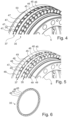
- the Fig.5 shows a detail of bearing rows 35 and 37 of a typical embodiment in a perspective, schematic view.
- the first bearing row 35 has first axial rolling elements 45 and first radial rolling elements 46 alternating 1:2.
- the second bearing row 37 has second axial rolling elements 47 and second radial rolling elements 48, also alternating 1:2.
- Spacers 49 are arranged between the axially and radially arranged rolling elements of both bearing rows 35 and 37. A spacer does not necessarily have to be present between the radially arranged rolling elements 46, 48.
- Fig.6 shows only rolling elements of a typical embodiment in a perspective, schematic view.
- a first bearing row 35 with first axial rolling elements 45 and first radial rolling elements 46 is shown, between which no spacers are arranged.
Landscapes
- Engineering & Computer Science (AREA)
- General Engineering & Computer Science (AREA)
- Mechanical Engineering (AREA)
- Rolling Contact Bearings (AREA)
- Retarders (AREA)
Applications Claiming Priority (1)
| Application Number | Priority Date | Filing Date | Title |
|---|---|---|---|
| DE102023101575.3A DE102023101575A1 (de) | 2023-01-23 | 2023-01-23 | Getriebe und Verwendung eines Getriebes |
Publications (1)
| Publication Number | Publication Date |
|---|---|
| EP4403797A1 true EP4403797A1 (fr) | 2024-07-24 |
Family
ID=89663361
Family Applications (1)
| Application Number | Title | Priority Date | Filing Date |
|---|---|---|---|
| EP24153174.8A Pending EP4403797A1 (fr) | 2023-01-23 | 2024-01-22 | Transmission et utilisation d'une transmission |
Country Status (6)
| Country | Link |
|---|---|
| US (1) | US20240247685A1 (fr) |
| EP (1) | EP4403797A1 (fr) |
| JP (1) | JP2024109526A (fr) |
| KR (1) | KR20240116982A (fr) |
| CN (1) | CN118375712A (fr) |
| DE (1) | DE102023101575A1 (fr) |
Citations (5)
| Publication number | Priority date | Publication date | Assignee | Title |
|---|---|---|---|---|
| DE102007011175A1 (de) | 2007-03-06 | 2008-09-11 | Wittenstein Ag | Koaxialgetriebe |
| US20150049975A1 (en) * | 2013-08-14 | 2015-02-19 | Mao-Tu Lee | Speed-reduction transmission bearing |
| EP2891834A2 (fr) * | 2010-02-12 | 2015-07-08 | Wittenstein AG | Transmission harmonique |
| DE102015105523A1 (de) | 2015-04-10 | 2016-10-13 | Wittenstein Ag | Getriebe |
| DE102015119582A1 (de) | 2015-11-12 | 2017-05-18 | Wittenstein Se | Getriebe |
Family Cites Families (5)
| Publication number | Priority date | Publication date | Assignee | Title |
|---|---|---|---|---|
| US1543791A (en) * | 1919-08-27 | 1925-06-30 | Pitter Walter Charles | Transmission gearing |
| US6416438B1 (en) * | 1999-04-30 | 2002-07-09 | ByongChol Choi | Transmitting unit |
| DE102007020415A1 (de) * | 2007-04-27 | 2008-11-06 | Wittenstein Ag | Koaxialgetriebe |
| DE102015105543A1 (de) * | 2015-04-10 | 2016-10-13 | Wittenstein Ag | Getriebekühlung |
| DE102020211034A1 (de) * | 2020-09-02 | 2022-03-03 | Aktiebolaget Skf | Käfigsegment für ein Wälzlager, insbesondere ein Wälzlager mit großem Durchmesser |
-
2023
- 2023-01-23 DE DE102023101575.3A patent/DE102023101575A1/de active Pending
-
2024
- 2024-01-18 CN CN202410074809.2A patent/CN118375712A/zh active Pending
- 2024-01-19 JP JP2024006604A patent/JP2024109526A/ja active Pending
- 2024-01-22 US US18/418,824 patent/US20240247685A1/en active Pending
- 2024-01-22 KR KR1020240009534A patent/KR20240116982A/ko active Pending
- 2024-01-22 EP EP24153174.8A patent/EP4403797A1/fr active Pending
Patent Citations (5)
| Publication number | Priority date | Publication date | Assignee | Title |
|---|---|---|---|---|
| DE102007011175A1 (de) | 2007-03-06 | 2008-09-11 | Wittenstein Ag | Koaxialgetriebe |
| EP2891834A2 (fr) * | 2010-02-12 | 2015-07-08 | Wittenstein AG | Transmission harmonique |
| US20150049975A1 (en) * | 2013-08-14 | 2015-02-19 | Mao-Tu Lee | Speed-reduction transmission bearing |
| DE102015105523A1 (de) | 2015-04-10 | 2016-10-13 | Wittenstein Ag | Getriebe |
| DE102015119582A1 (de) | 2015-11-12 | 2017-05-18 | Wittenstein Se | Getriebe |
Also Published As
| Publication number | Publication date |
|---|---|
| KR20240116982A (ko) | 2024-07-30 |
| US20240247685A1 (en) | 2024-07-25 |
| DE102023101575A1 (de) | 2024-07-25 |
| JP2024109526A (ja) | 2024-08-14 |
| CN118375712A (zh) | 2024-07-23 |
Similar Documents
| Publication | Publication Date | Title |
|---|---|---|
| EP3354934B1 (fr) | Engrenage coaxiale à traduction positive | |
| EP0839293B1 (fr) | Engrenage planetaire | |
| DE3738521C1 (de) | Planetengetriebe | |
| EP3507526A1 (fr) | Boîte de vitesses à trains épicycloïdaux | |
| EP0981697A1 (fr) | Boite planetaire | |
| EP3168496B1 (fr) | Engrenage et methode pour produire un tel engrenage | |
| EP2693079A2 (fr) | Train épicycloïdal et appareil de manipulation équipé d'un tel train épicycloïdal | |
| EP2063200A1 (fr) | Agencement d'entraînement à deux axes | |
| EP1188002B1 (fr) | Boite planetaire | |
| DE10329870B3 (de) | Zahnrad und Zahnradsatz | |
| DE102021121736A1 (de) | Set aus Komponenten zum Zusammenbau von steigungstreuen Planetenwälzgetrieben | |
| DE3014860A1 (de) | Uebersetzungsgetriebe | |
| DE102021104649A1 (de) | Lenkungsaktuator für eine Hinterachslenkung und Verfahren zur Montage eines Lenkungsaktuators | |
| EP3982005B1 (fr) | Engrenage coaxial | |
| EP3169913B1 (fr) | Engrenage harmonique à fonctionnement à sec | |
| EP1616113B1 (fr) | Engrenage planetaire | |
| EP4403797A1 (fr) | Transmission et utilisation d'une transmission | |
| EP3816478A1 (fr) | Engrenage coaxial à dents mobiles | |
| EP3828444A1 (fr) | Boîte de vitesses | |
| DE102019212221A1 (de) | Wellgetriebe | |
| DE102009002067A1 (de) | Taumelradwolfromgetriebe | |
| DE102019212220B4 (de) | Wellgetriebe | |
| EP1831590B1 (fr) | Dispositif, notamment engrenage planetaire, comprenant un corps de base en anneau | |
| DE112022002761T5 (de) | Planetenuntersetzungsgetriebe mit mindestens einem Planetenrad mit mindestens einem Außengewindeabschnitt | |
| DE102024110219A1 (de) | Planetengetriebe sowie Antriebseinheit mit einem solchen Planetengetriebe |
Legal Events
| Date | Code | Title | Description |
|---|---|---|---|
| PUAI | Public reference made under article 153(3) epc to a published international application that has entered the european phase |
Free format text: ORIGINAL CODE: 0009012 |
|
| STAA | Information on the status of an ep patent application or granted ep patent |
Free format text: STATUS: THE APPLICATION HAS BEEN PUBLISHED |
|
| AK | Designated contracting states |
Kind code of ref document: A1 Designated state(s): AL AT BE BG CH CY CZ DE DK EE ES FI FR GB GR HR HU IE IS IT LI LT LU LV MC ME MK MT NL NO PL PT RO RS SE SI SK SM TR |
|
| STAA | Information on the status of an ep patent application or granted ep patent |
Free format text: STATUS: REQUEST FOR EXAMINATION WAS MADE |
|
| 17P | Request for examination filed |
Effective date: 20250109 |
|
| GRAP | Despatch of communication of intention to grant a patent |
Free format text: ORIGINAL CODE: EPIDOSNIGR1 |
|
| STAA | Information on the status of an ep patent application or granted ep patent |
Free format text: STATUS: GRANT OF PATENT IS INTENDED |
|
| RIC1 | Information provided on ipc code assigned before grant |
Ipc: F16H 25/06 20060101AFI20260217BHEP Ipc: F16C 19/36 20060101ALI20260217BHEP Ipc: F16C 19/38 20060101ALI20260217BHEP |
|
| INTG | Intention to grant announced |
Effective date: 20260304 |