EP4403787A1 - Limited stroke linear guide device - Google Patents
Limited stroke linear guide device Download PDFInfo
- Publication number
- EP4403787A1 EP4403787A1 EP22869706.6A EP22869706A EP4403787A1 EP 4403787 A1 EP4403787 A1 EP 4403787A1 EP 22869706 A EP22869706 A EP 22869706A EP 4403787 A1 EP4403787 A1 EP 4403787A1
- Authority
- EP
- European Patent Office
- Prior art keywords
- cage
- shaft member
- guide
- guide member
- locking protrusion
- Prior art date
- Legal status (The legal status is an assumption and is not a legal conclusion. Google has not performed a legal analysis and makes no representation as to the accuracy of the status listed.)
- Pending
Links
Images

Classifications
-
- F—MECHANICAL ENGINEERING; LIGHTING; HEATING; WEAPONS; BLASTING
- F16—ENGINEERING ELEMENTS AND UNITS; GENERAL MEASURES FOR PRODUCING AND MAINTAINING EFFECTIVE FUNCTIONING OF MACHINES OR INSTALLATIONS; THERMAL INSULATION IN GENERAL
- F16C—SHAFTS; FLEXIBLE SHAFTS; ELEMENTS OR CRANKSHAFT MECHANISMS; ROTARY BODIES OTHER THAN GEARING ELEMENTS; BEARINGS
- F16C29/00—Bearings for parts moving only linearly
- F16C29/04—Ball or roller bearings
-
- F—MECHANICAL ENGINEERING; LIGHTING; HEATING; WEAPONS; BLASTING
- F16—ENGINEERING ELEMENTS AND UNITS; GENERAL MEASURES FOR PRODUCING AND MAINTAINING EFFECTIVE FUNCTIONING OF MACHINES OR INSTALLATIONS; THERMAL INSULATION IN GENERAL
- F16C—SHAFTS; FLEXIBLE SHAFTS; ELEMENTS OR CRANKSHAFT MECHANISMS; ROTARY BODIES OTHER THAN GEARING ELEMENTS; BEARINGS
- F16C29/00—Bearings for parts moving only linearly
- F16C29/04—Ball or roller bearings
- F16C29/06—Ball or roller bearings in which the rolling bodies circulate partly without carrying load
- F16C29/0602—Details of the bearing body or carriage or parts thereof, e.g. methods for manufacturing or assembly
- F16C29/0604—Details of the bearing body or carriage or parts thereof, e.g. methods for manufacturing or assembly of the load bearing section
- F16C29/0607—Details of the bearing body or carriage or parts thereof, e.g. methods for manufacturing or assembly of the load bearing section of parts or members for retaining the rolling elements, i.e. members to prevent the rolling elements from falling out of the bearing body or carriage
-
- F—MECHANICAL ENGINEERING; LIGHTING; HEATING; WEAPONS; BLASTING
- F16—ENGINEERING ELEMENTS AND UNITS; GENERAL MEASURES FOR PRODUCING AND MAINTAINING EFFECTIVE FUNCTIONING OF MACHINES OR INSTALLATIONS; THERMAL INSULATION IN GENERAL
- F16C—SHAFTS; FLEXIBLE SHAFTS; ELEMENTS OR CRANKSHAFT MECHANISMS; ROTARY BODIES OTHER THAN GEARING ELEMENTS; BEARINGS
- F16C29/00—Bearings for parts moving only linearly
- F16C29/04—Ball or roller bearings
- F16C29/06—Ball or roller bearings in which the rolling bodies circulate partly without carrying load
- F16C29/0633—Ball or roller bearings in which the rolling bodies circulate partly without carrying load with a bearing body defining a U-shaped carriage, i.e. surrounding a guide rail or track on three sides
- F16C29/0635—Ball or roller bearings in which the rolling bodies circulate partly without carrying load with a bearing body defining a U-shaped carriage, i.e. surrounding a guide rail or track on three sides whereby the return paths are provided as bores in a main body of the U-shaped carriage, e.g. the main body of the U-shaped carriage is a single part with end caps provided at each end
- F16C29/0638—Ball or roller bearings in which the rolling bodies circulate partly without carrying load with a bearing body defining a U-shaped carriage, i.e. surrounding a guide rail or track on three sides whereby the return paths are provided as bores in a main body of the U-shaped carriage, e.g. the main body of the U-shaped carriage is a single part with end caps provided at each end with balls
-
- F—MECHANICAL ENGINEERING; LIGHTING; HEATING; WEAPONS; BLASTING
- F16—ENGINEERING ELEMENTS AND UNITS; GENERAL MEASURES FOR PRODUCING AND MAINTAINING EFFECTIVE FUNCTIONING OF MACHINES OR INSTALLATIONS; THERMAL INSULATION IN GENERAL
- F16C—SHAFTS; FLEXIBLE SHAFTS; ELEMENTS OR CRANKSHAFT MECHANISMS; ROTARY BODIES OTHER THAN GEARING ELEMENTS; BEARINGS
- F16C29/00—Bearings for parts moving only linearly
- F16C29/10—Arrangements for locking the bearings
-
- F—MECHANICAL ENGINEERING; LIGHTING; HEATING; WEAPONS; BLASTING
- F16—ENGINEERING ELEMENTS AND UNITS; GENERAL MEASURES FOR PRODUCING AND MAINTAINING EFFECTIVE FUNCTIONING OF MACHINES OR INSTALLATIONS; THERMAL INSULATION IN GENERAL
- F16C—SHAFTS; FLEXIBLE SHAFTS; ELEMENTS OR CRANKSHAFT MECHANISMS; ROTARY BODIES OTHER THAN GEARING ELEMENTS; BEARINGS
- F16C33/00—Parts of bearings; Special methods for making bearings or parts thereof
- F16C33/30—Parts of ball or roller bearings
- F16C33/38—Ball cages
- F16C33/40—Ball cages for multiple rows of balls
-
- F—MECHANICAL ENGINEERING; LIGHTING; HEATING; WEAPONS; BLASTING
- F16—ENGINEERING ELEMENTS AND UNITS; GENERAL MEASURES FOR PRODUCING AND MAINTAINING EFFECTIVE FUNCTIONING OF MACHINES OR INSTALLATIONS; THERMAL INSULATION IN GENERAL
- F16C—SHAFTS; FLEXIBLE SHAFTS; ELEMENTS OR CRANKSHAFT MECHANISMS; ROTARY BODIES OTHER THAN GEARING ELEMENTS; BEARINGS
- F16C33/00—Parts of bearings; Special methods for making bearings or parts thereof
- F16C33/30—Parts of ball or roller bearings
- F16C33/46—Cages for rollers or needles
- F16C33/56—Selection of substances
-
- F—MECHANICAL ENGINEERING; LIGHTING; HEATING; WEAPONS; BLASTING
- F16—ENGINEERING ELEMENTS AND UNITS; GENERAL MEASURES FOR PRODUCING AND MAINTAINING EFFECTIVE FUNCTIONING OF MACHINES OR INSTALLATIONS; THERMAL INSULATION IN GENERAL
- F16C—SHAFTS; FLEXIBLE SHAFTS; ELEMENTS OR CRANKSHAFT MECHANISMS; ROTARY BODIES OTHER THAN GEARING ELEMENTS; BEARINGS
- F16C2226/00—Joining parts; Fastening; Assembling or mounting parts
- F16C2226/50—Positive connections
-
- F—MECHANICAL ENGINEERING; LIGHTING; HEATING; WEAPONS; BLASTING
- F16—ENGINEERING ELEMENTS AND UNITS; GENERAL MEASURES FOR PRODUCING AND MAINTAINING EFFECTIVE FUNCTIONING OF MACHINES OR INSTALLATIONS; THERMAL INSULATION IN GENERAL
- F16C—SHAFTS; FLEXIBLE SHAFTS; ELEMENTS OR CRANKSHAFT MECHANISMS; ROTARY BODIES OTHER THAN GEARING ELEMENTS; BEARINGS
- F16C33/00—Parts of bearings; Special methods for making bearings or parts thereof
- F16C33/30—Parts of ball or roller bearings
- F16C33/306—Means to synchronise movements
Definitions
- the present invention relates to a linear guide device for linearly moving an article within a predetermined stroke range.
- This linear guide device includes: a shaft member which is formed to have a substantially rectangular shape in cross section, and has right and left side surfaces each having a rolling surface for rolling elements; a guide member which is movable along the shaft member; a large number of rolling elements configured to roll between the shaft member and the guide member while bearing a load; and a cage, which is configured to be arranged in a gap between the shaft member and the guide member, and has the large number of rolling elements rotatably arranged in the cage.
- the guide member is formed into a groove shape with a guide groove that allows the shaft member to be loosely fitted to the guide groove.
- Rolling surfaces that face rolling surfaces of the shaft member are provided on both side surfaces of the guide groove.
- the rolling elements are in contact with the rolling surfaces of the shaft member and the rolling surfaces of the guide member, and roll between the shaft member and the guide member.
- the cage is formed into a thin plate shape, and is present in the gap between the shaft member and the guide member.
- the cage has a large number of accommodation holes that allow the large number of rolling elements to be arranged at predetermined intervals. The rolling elements freely rotates inside the accommodation holes of the cage while rolling on the rolling surfaces of the shaft member and the rolling surfaces of the guide member.
- this rolling guide device includes a mechanism for restricting a stroke range of the cage with respect to the guide member and a stroke range of the cage with respect to the shaft member.
- An elongated regulating hole is formed in the cage along a moving direction of the guide member, and a locking protrusion is provided inside the guide groove of the guide member.
- the locking protrusion is inserted into the regulating hole of the cage.
- the rolling elements are not only in rolling contact but also in slight sliding contact with the rolling surfaces of the shaft member and the guide member. Accordingly, when the guide member repeatedly performs a reciprocating motion with respect to the shaft member, a position of the cage is gradually displaced relative to the guide member and the shaft member. When such positional displacement of the cage occurs, the stroke range of the guide member with respect to the shaft member is excessively restricted, and hence it is required to perform a reset operation for periodically eliminating the positional displacement, during operation of the guide member.
- This reset operation is performed by forcibly moving the guide member under a state in which the locking protrusion is locked to an end part of the regulating hole of the cage, and accordingly, the cage moves relative to the shaft member while dragging the rolling elements, and then is brought into abutment against the stopper.
- the present invention has been made in view of the above-mentioned problems, and has an object to provide a finite stroke type linear guide device capable of ensuring sufficient strength of a locking protrusion or a regulating hole against a reset operation for a cage, and also minimizing a gap between a shaft member and a guide member to achieve reduction in size of the entire device.
- a linear guide device includes: a guide member including a guide groove surrounded by a base portion and a pair of side wall portions, each of the side wall portions having a rolling groove for rolling elements, which is formed along a longitudinal direction of the guide groove so as to face the guide groove; a shaft member which is configured to move inside the guide groove of the guide member along the longitudinal direction of the guide groove, and includes rolling grooves facing the rolling grooves of the guide member; a large number of rolling elements configured to roll between the rolling groove of the guide member and the rolling groove of the shaft member while bearing a load; and a cage, which is configured to be arranged inside the guide groove of the guide member so as to be present in a gap between the guide member and the shaft member, and has the large number of rolling elements being rotatably arranged in the cage.
- any one of the guide member or the shaft member has a stopper provided at an end part in a longitudinal direction and configured to allow the cage to be brought into abutment against the stopper.
- another one of the guide member or the shaft member has a regulating hole which is elongated along a moving direction of the shaft member, the cage has a locking protrusion provided upright on the cage and having a distal end part inserted into the regulating hole.
- a positional relationship between the guide member and the cage, or a positional relationship between the shaft member and the cage is restricted by the regulating hole and the locking protrusion.
- the locking protrusion is provided upright on the cage. Hence, even when the locking protrusion is strongly brought into abutment against the end part of the regulating hole, there is no concern in that deformation, such as buckling, of the regulating hole or the locking protrusion may be caused.
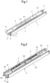
- FIG. 1 is illustration of one example of a linear guide device 1 to which the present invention has been applied.
- the linear guide device 1 is configured by combining a guide member 3 and a shaft member 4 with each other through intermediation of a large number of rollers serving as rolling elements.
- the shaft member 4 is freely moved in a longitudinal direction of the guide member 3 (direction indicated by the arrow line A of FIG. 1 ) so that the shaft member 4 can be accommodated inside the guide member 3, or the shaft member 4 can be pulled out from the guide member 3.
- the movable portion can be freely moved relative to the fixed portion within a predetermined stroke range.
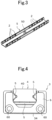
- FIG. 2 is illustration of the guide member 3 from which the shaft member 4 has been removed.
- the guide member 3 is formed into a substantially C-shape in cross section with a guide groove 30, and includes a base portion 31 and a pair of side wall portions 32.
- the pair of side wall portions 32 stand upright from the base portion 31 so that the guide groove 30 is located between the pair of side wall portions 32, and each of the side wall portions 32 is orthogonal to the base portion 31.
- the guide groove 30 functions as an accommodation space for the shaft member 4.
- a rolling groove 33 for the rollers 2 is formed in each of the side wall portions 32 so as to face the guide groove 30, and the rolling groove 33 extends over the entire length of the guide member 3 along a longitudinal direction of the guide groove 30.
- the base portion 31 includes a mounting surface 34 which is to be brought into abutment against the fixed portion of the mechanical device.
- the shaft member 4 is a rod-shaped member which is to be accommodated inside the guide groove 30 of the guide member 3, and has a substantially rectangular cross section orthogonal to the longitudinal direction. Further, the shaft member 4 includes a mounting surface 40 which is to be brought into abutment against the movable portion of the mechanical device, and the mounting surface 40 is arranged at a position slightly protruding from end parts of the pair of side wall portions 32 of the guide member 3, that is, outside the guide groove 30 of the guide member 3. As a result, the movable portion and the guide member 3 are prevented from interfering with each other.
- a rolling groove 41 for the rollers 2 is formed in each of wall surfaces of the shaft member 4 which face the side wall portions 32 of the guide member 3, respectively.
- the rolling groove 41 on the shaft member 4 side is formed at a position directly opposing the rolling groove 33 on the guide member 3 side, and the large number of rollers 2 are arranged between the rolling groove 33 on the guide member 3 side and the rolling groove 41 on the shaft member 4 side.
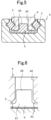
- a cage 5 is arranged inside the guide groove 30 of the guide member 3, and under a state in which the guide member 3 and the shaft member 4 have been combined with each other (see FIG. 1 ), the cage 5 is present in a gap between the guide member 3 and the shaft member 4.
- the cage 5 is formed into a groove shape extending along the guide groove 30 of the guide member 3, and has a large number of accommodation holes in which the rollers 2 are to be arranged and which are formed at predetermined intervals along the rolling groove 33 of the guide member 3.
- the rollers 2 are rotatably held inside the accommodation holes, and are in contact with the rolling groove 33 of the guide member 3 and the rolling groove 41 of the shaft member 4.
- the cage 5 is manufactured by injection molding of a synthetic resin, and after the injection molding, the rollers 2 are inserted into the accommodation holes, respectively.
- the rollers 2 are arranged as so-called cross rollers in the cage 5, and two rollers 2 adjacent to each other in the same rolling groove 33 have respective rotation axes orthogonal to each other. Accordingly, the rolling groove 33 of the guide member 3 and the rolling groove 41 of the shaft member 4 are each formed as a V-shaped groove obtained by a pair of rolling surfaces intersecting with each other at an angle of 90 degrees.
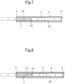
- FIG. 4 is illustration of a positional relationship among the guide member 3, the cage 5, and the shaft member 4 when observed from the longitudinal direction of the guide member. As illustrated in FIG. 4 , each of the stoppers 6 is formed in such a size that the stopper 6 does not overlap the shaft member 4, and overlaps a part of the cage 5.
- the shaft member when the shaft member is moved relative to the guide member, the shaft member is pulled out from the guide groove of the guide member without interfering with the stopper 6, but the cage 5 is brought into abutment against the stopper 6 at the end part of the guide member 3.
- the cage 5 can move only inside the guide groove 30 of the guide member 3.
- the cage 5 includes a locking protrusion 50 having a columnar shape, in the vicinity of a center in the longitudinal direction.
- the locking protrusion 50 stands upright from the cage 5 toward the shaft member 4, and as illustrated in FIG. 5 , a distal end part of the locking protrusion 50 is inserted into a regulating hole 42 formed in the shaft member 4.
- the regulating hole 42 of the shaft member 4 is formed into an elongated slit shape extending along a moving direction of the shaft member 4 (see FIG. 1 ), and extends through the shaft member 4. As long as the regulating hole 42 can receive a distal end of the locking protrusion 50, it is not required that the regulating hole 42 be formed to extend through the shaft member 4.
- the regulating hole 42 has a width which is set to be larger than a diameter of the locking protrusion 50, and hence, when the shaft member 4 moves relative to the cage 5, the locking protrusion 50 can freely move inside the regulating hole 42. Further, both end parts of the regulating hole 42 in the longitudinal direction are each formed into a semicircular shape approximate to an outer shape of the locking protrusion 50, and thus, are configured such that the locking protrusion 50 of the cage 5 is brought into contact with each of the both end parts of the regulating hole 42 under a state close to surface contact.
- the both end parts of the regulating hole 42 in the longitudinal direction be each formed into a rectangular shape so that the locking protrusion 50 is brought into surface contact with the both end parts of the regulating hole 42.
- the locking protrusion 50 provided upright on the cage 5 has a root part 51 with a diameter which is gradually increased so that the root part 51 is smoothly continuous to the cage 5.
- the regulating hole 42 of the shaft member 4 has an edge part which faces the cage 5, and an expanded portion 43 is provided at the edge part to thereby prevent interference between the root part 51 of the locking protrusion 50 and the shaft member 4.
- the cage 5 moves relative to the guide member 3 by 1/2 of a stroke amount of the shaft member 4 with respect to the guide member 3. Accordingly, a length of the regulating hole 42 in the moving direction of the shaft member 4 is set to 1/2 of the stroke amount of the shaft member 4 with respect to the guide member 3.
- the locking protrusion 50 is located at a center of the regulating hole 42 in the longitudinal direction.
- the cage 5 moves inside the guide groove 30 of the guide member 3, and simultaneously, the shaft member 4 moves relative to the cage 5 by the same amount as a movement amount of the cage 5 with respect to the guide member 3.
- the cage 5 is brought into abutment against the stopper 6, and at the same time, the locking protrusion 50 of the cage 5 reaches the end part of the regulating hole 42 of the shaft member 4 in the longitudinal direction, and hence, the shaft member 4 becomes immovable relative to the cage 5. That is, as illustrated in FIG.
- a position of the shaft member 4 at the time when the cage 5 is brought into abutment against the stopper 6, and simultaneously, the locking protrusion 50 is brought into abutment against the end part of the regulating hole 42 in the longitudinal direction is a maximum stroke position of the shaft member 4 with respect to the guide member 3.
- a position of the cage 5 is displaced relative to the guide member 3 in some cases.
- the locking protrusion 50 of the cage 5 reaches the end part of the regulating hole 42 of the shaft member 4, but the cage 5 is not brought into abutment against the stopper 6 fixed to the guide member 3.
- the cage 5 is brought into abutment against the stopper 6 fixed to the guide member 3, but the locking protrusion 50 of the cage 5 does not reach the end part of the regulating hole 42 of the shaft member 4.
- a stroke amount of the shaft member 4 with respect to the guide member 3 becomes smaller than the maximum stroke amount illustrated in FIG. 7 . Further, when the shaft member 4 is forcibly moved to the maximum stroke amount, the rollers 2 serving as the rolling elements are brought into sliding contact with the rolling groove 33 of the guide member 3 and the rolling groove 41 of the shaft member 4.
- the positional displacement among those three members can be reset by forcibly moving the shaft member 4 relative to the guide member 3. Such a reset operation is performed once each time the shaft member 4 is caused to stroke with respect to the guide member 3 a predetermined number of times.
- the shaft member 4 is forcibly moved leftward on the drawing sheet from a state as illustrated in FIG. 8 or FIG. 9 , to thereby produce a state, as illustrated in FIG. 7 , in which the cage 5 is brought into abutment against the stopper 6, and simultaneously, the locking protrusion 50 of the cage 5 is locked to the end part of the regulating hole 42 of the shaft member 4.
- the rollers 2 serving as the rolling elements slide on the rolling groove 41 of the shaft member 4 and the rolling groove 33 of the guide member 3 without rolling.
- the regulating hole 42 into which the distal end of the locking protrusion 50 is to be inserted is formed in the shaft member 4.
- the locking protrusion 50 is provided upright on the cage 5, and hence, even when a wall thickness of the cage 5 is reduced, it is possible to provide sufficient strength for the locking protrusion 50 by designing any appropriate shape and thickness of the locking protrusion 50 and any appropriate shape of the root part of the locking protrusion 50. As a result, deformation of the locking protrusion 50 due to the abutment against the regulating hole 42 can be prevented.
- the locking protrusion 50 can be formed integrally with the cage 5 by using a method such as injection molding of a synthetic resin. Also in this respect, it is possible to provide sufficient strength for the locking protrusion 50 while enhancing a degree of freedom in design of the cage 5 including the locking protrusion 50.
- the linear guide device of this embodiment sufficient strength of the locking protrusion 50 or the regulating hole 42 against the reset operation for the cage 5 can be ensured, and the degree of freedom in design of the cage 5 can be enhanced. Accordingly, the wall thickness of the cage 5 can be set smaller, and hence it is possible to minimize the gap between the guide member 3 and the shaft member 4 to achieve reduction in size of the linear guide device.
- the regulating hole 42 into which the distal end of the locking protrusion 50 of the cage 5 is to be inserted is formed in the shaft member 4.
- the present invention can be implemented.
- the stoppers 6 for locking the cage 5 are provided at the both ends of the guide member 3 in the longitudinal direction, respectively.
- the stopper 6 may be provided only at one end part of the guide member 3 in the longitudinal direction.
- a method of fixing the stoppers 6 to the guide member 3 or the shaft member 4 is not limited to screwing, but may be appropriately changed in design as long as movement of the cage 5 can be reliably locked by the stoppers 6.
Landscapes
- Engineering & Computer Science (AREA)
- General Engineering & Computer Science (AREA)
- Mechanical Engineering (AREA)
- Bearings For Parts Moving Linearly (AREA)
- Rolling Contact Bearings (AREA)
Abstract
Description
- The present invention relates to a linear guide device for linearly moving an article within a predetermined stroke range.
- As a linear guide device of this type, there has been known a linear guide device as disclosed in Patent Literature 1. This linear guide device includes: a shaft member which is formed to have a substantially rectangular shape in cross section, and has right and left side surfaces each having a rolling surface for rolling elements; a guide member which is movable along the shaft member; a large number of rolling elements configured to roll between the shaft member and the guide member while bearing a load; and a cage, which is configured to be arranged in a gap between the shaft member and the guide member, and has the large number of rolling elements rotatably arranged in the cage.
- The guide member is formed into a groove shape with a guide groove that allows the shaft member to be loosely fitted to the guide groove. Rolling surfaces that face rolling surfaces of the shaft member are provided on both side surfaces of the guide groove. The rolling elements are in contact with the rolling surfaces of the shaft member and the rolling surfaces of the guide member, and roll between the shaft member and the guide member. The cage is formed into a thin plate shape, and is present in the gap between the shaft member and the guide member. The cage has a large number of accommodation holes that allow the large number of rolling elements to be arranged at predetermined intervals. The rolling elements freely rotates inside the accommodation holes of the cage while rolling on the rolling surfaces of the shaft member and the rolling surfaces of the guide member.
- When the guide member moves along the shaft member, theoretically, the cage moves relative to the shaft member by 1/2 of a movement amount of the guide member. When the cage comes off from the area between the shaft member and the guide member, there arises a concern in that the rolling elements may roll out of the accommodation holes of the cage. Thus, this rolling guide device includes a mechanism for restricting a stroke range of the cage with respect to the guide member and a stroke range of the cage with respect to the shaft member.
- An elongated regulating hole is formed in the cage along a moving direction of the guide member, and a locking protrusion is provided inside the guide groove of the guide member. The locking protrusion is inserted into the regulating hole of the cage. With this configuration, the stroke range of the cage with respect to the guide member is restricted. Further, a pair of stoppers are provided in the vicinity of both ends of the shaft member in a longitudinal direction, respectively, and hence, the cage can make a stroke along the shaft member only between those stoppers.
- [PTL 1]
JP 2004-19767 A - The rolling elements are not only in rolling contact but also in slight sliding contact with the rolling surfaces of the shaft member and the guide member. Accordingly, when the guide member repeatedly performs a reciprocating motion with respect to the shaft member, a position of the cage is gradually displaced relative to the guide member and the shaft member. When such positional displacement of the cage occurs, the stroke range of the guide member with respect to the shaft member is excessively restricted, and hence it is required to perform a reset operation for periodically eliminating the positional displacement, during operation of the guide member. This reset operation is performed by forcibly moving the guide member under a state in which the locking protrusion is locked to an end part of the regulating hole of the cage, and accordingly, the cage moves relative to the shaft member while dragging the rolling elements, and then is brought into abutment against the stopper.
- In this reset operation, the end part of the regulating hole formed in the cage is strongly pressed by the locking protrusion of the guide member, and hence there is a concern in that buckling may occur at the end part of the regulating hole in the cage. As a countermeasure thereagainst, it is conceivable to ensure the strength of the cage by, for example, increasing a wall thickness of the cage. However, for such a countermeasure, it is required to enlarge the gap between the shaft member and the guide member, and hence there has been a problem in that it is difficult to achieve reduction in size of the guide member, that is, reduction in size of the linear guide device.
- The present invention has been made in view of the above-mentioned problems, and has an object to provide a finite stroke type linear guide device capable of ensuring sufficient strength of a locking protrusion or a regulating hole against a reset operation for a cage, and also minimizing a gap between a shaft member and a guide member to achieve reduction in size of the entire device.
- That is, a linear guide device according to the present invention includes: a guide member including a guide groove surrounded by a base portion and a pair of side wall portions, each of the side wall portions having a rolling groove for rolling elements, which is formed along a longitudinal direction of the guide groove so as to face the guide groove; a shaft member which is configured to move inside the guide groove of the guide member along the longitudinal direction of the guide groove, and includes rolling grooves facing the rolling grooves of the guide member; a large number of rolling elements configured to roll between the rolling groove of the guide member and the rolling groove of the shaft member while bearing a load; and a cage, which is configured to be arranged inside the guide groove of the guide member so as to be present in a gap between the guide member and the shaft member, and has the large number of rolling elements being rotatably arranged in the cage. Further, any one of the guide member or the shaft member has a stopper provided at an end part in a longitudinal direction and configured to allow the cage to be brought into abutment against the stopper. While another one of the guide member or the shaft member has a regulating hole which is elongated along a moving direction of the shaft member, the cage has a locking protrusion provided upright on the cage and having a distal end part inserted into the regulating hole.
- According to the linear guide device of the present invention, a positional relationship between the guide member and the cage, or a positional relationship between the shaft member and the cage is restricted by the regulating hole and the locking protrusion. In this case, while the regulating hole is formed in the guide member or the shaft member, the locking protrusion is provided upright on the cage. Hence, even when the locking protrusion is strongly brought into abutment against the end part of the regulating hole, there is no concern in that deformation, such as buckling, of the regulating hole or the locking protrusion may be caused. Accordingly, it is possible to ensure sufficient strength of the locking protrusion or the regulating hole against the reset operation for the cage, and also to enhance a degree of freedom in design of the cage and minimize the gap between the shaft member and the guide member to achieve reduction in size of the entire device.
-
-
FIG. 1 is a perspective view for illustrating one example of a linear guide device according to one embodiment of the present invention. -
FIG. 2 is a perspective view for illustrating a state in which a shaft member has been removed from the linear guide device illustrated inFIG. 1 . -
FIG. 3 is a perspective view for illustrating a cage of the linear guide device illustrated inFIG. 1 . -
FIG. 4 is a front view for illustrating the linear guide device illustrated inFIG. 1 when observed from a longitudinal direction of a guide member. -
FIG. 5 is a sectional view taken along the line V-V ofFIG. 1 . -
FIG. 6 is a sectional view for illustrating a relationship between a locking protrusion of the cage and a regulating hole of the shaft member. -
FIG. 7 is a plan view for illustrating a maximum stroke position of the shaft member with respect to the guide member. -
FIG. 8 is a plan view for illustrating a state in which positional displacement has occurred between the cage and the guide member. -
FIG. 9 is a plan view for illustrating a state in which positional displacement has occurred between the cage and the shaft member. - Now, a linear guide device according to the present invention is described in detail with reference to the attached drawings.
-
FIG. 1 is illustration of one example of a linear guide device 1 to which the present invention has been applied. As illustrated inFIG. 1 , the linear guide device 1 is configured by combining aguide member 3 and ashaft member 4 with each other through intermediation of a large number of rollers serving as rolling elements. Theshaft member 4 is freely moved in a longitudinal direction of the guide member 3 (direction indicated by the arrow line A ofFIG. 1 ) so that theshaft member 4 can be accommodated inside theguide member 3, or theshaft member 4 can be pulled out from theguide member 3. Accordingly, for example, when theguide member 3 is fixed to a fixed portion of a mechanical device, and theshaft member 4 is fixed to a movable portion of the mechanical device, the movable portion can be freely moved relative to the fixed portion within a predetermined stroke range. -
FIG. 2 is illustration of theguide member 3 from which theshaft member 4 has been removed. Theguide member 3 is formed into a substantially C-shape in cross section with aguide groove 30, and includes abase portion 31 and a pair ofside wall portions 32. The pair ofside wall portions 32 stand upright from thebase portion 31 so that theguide groove 30 is located between the pair ofside wall portions 32, and each of theside wall portions 32 is orthogonal to thebase portion 31. The guide groove 30 functions as an accommodation space for theshaft member 4. Arolling groove 33 for therollers 2 is formed in each of theside wall portions 32 so as to face theguide groove 30, and therolling groove 33 extends over the entire length of theguide member 3 along a longitudinal direction of theguide groove 30. Further, thebase portion 31 includes amounting surface 34 which is to be brought into abutment against the fixed portion of the mechanical device. - Meanwhile, as illustrated in
FIG. 1 , theshaft member 4 is a rod-shaped member which is to be accommodated inside theguide groove 30 of theguide member 3, and has a substantially rectangular cross section orthogonal to the longitudinal direction. Further, theshaft member 4 includes amounting surface 40 which is to be brought into abutment against the movable portion of the mechanical device, and themounting surface 40 is arranged at a position slightly protruding from end parts of the pair ofside wall portions 32 of theguide member 3, that is, outside theguide groove 30 of theguide member 3. As a result, the movable portion and theguide member 3 are prevented from interfering with each other. Arolling groove 41 for therollers 2 is formed in each of wall surfaces of theshaft member 4 which face theside wall portions 32 of theguide member 3, respectively. Therolling groove 41 on theshaft member 4 side is formed at a position directly opposing therolling groove 33 on theguide member 3 side, and the large number ofrollers 2 are arranged between therolling groove 33 on theguide member 3 side and therolling groove 41 on theshaft member 4 side. - A
cage 5 is arranged inside theguide groove 30 of theguide member 3, and under a state in which theguide member 3 and theshaft member 4 have been combined with each other (seeFIG. 1 ), thecage 5 is present in a gap between theguide member 3 and theshaft member 4. As illustrated inFIG. 3 , thecage 5 is formed into a groove shape extending along theguide groove 30 of theguide member 3, and has a large number of accommodation holes in which therollers 2 are to be arranged and which are formed at predetermined intervals along the rollinggroove 33 of theguide member 3. Therollers 2 are rotatably held inside the accommodation holes, and are in contact with the rollinggroove 33 of theguide member 3 and the rollinggroove 41 of theshaft member 4. In this embodiment, thecage 5 is manufactured by injection molding of a synthetic resin, and after the injection molding, therollers 2 are inserted into the accommodation holes, respectively. - In this embodiment, the
rollers 2 are arranged as so-called cross rollers in thecage 5, and tworollers 2 adjacent to each other in the same rollinggroove 33 have respective rotation axes orthogonal to each other. Accordingly, the rollinggroove 33 of theguide member 3 and the rollinggroove 41 of theshaft member 4 are each formed as a V-shaped groove obtained by a pair of rolling surfaces intersecting with each other at an angle of 90 degrees. - A pair of
stoppers 6 for locking movement of thecage 5 are provided at both end parts of theguide member 3 in the longitudinal direction, respectively. Further, thosestoppers 6 are fastened to end surfaces of theguide member 3, respectively, with fixingscrews 60.FIG. 4 is illustration of a positional relationship among theguide member 3, thecage 5, and theshaft member 4 when observed from the longitudinal direction of the guide member. As illustrated inFIG. 4 , each of thestoppers 6 is formed in such a size that thestopper 6 does not overlap theshaft member 4, and overlaps a part of thecage 5. Accordingly, when the shaft member is moved relative to the guide member, the shaft member is pulled out from the guide groove of the guide member without interfering with thestopper 6, but thecage 5 is brought into abutment against thestopper 6 at the end part of theguide member 3. Hence, thecage 5 can move only inside theguide groove 30 of theguide member 3. - Further, the
cage 5 includes a lockingprotrusion 50 having a columnar shape, in the vicinity of a center in the longitudinal direction. The lockingprotrusion 50 stands upright from thecage 5 toward theshaft member 4, and as illustrated inFIG. 5 , a distal end part of the lockingprotrusion 50 is inserted into a regulatinghole 42 formed in theshaft member 4. The regulatinghole 42 of theshaft member 4 is formed into an elongated slit shape extending along a moving direction of the shaft member 4 (seeFIG. 1 ), and extends through theshaft member 4. As long as the regulatinghole 42 can receive a distal end of the lockingprotrusion 50, it is not required that the regulatinghole 42 be formed to extend through theshaft member 4. - The regulating
hole 42 has a width which is set to be larger than a diameter of the lockingprotrusion 50, and hence, when theshaft member 4 moves relative to thecage 5, the lockingprotrusion 50 can freely move inside the regulatinghole 42. Further, both end parts of the regulatinghole 42 in the longitudinal direction are each formed into a semicircular shape approximate to an outer shape of the lockingprotrusion 50, and thus, are configured such that the lockingprotrusion 50 of thecage 5 is brought into contact with each of the both end parts of the regulatinghole 42 under a state close to surface contact. In a case in which the lockingprotrusion 50 is formed into a prismatic shape, it is preferred that the both end parts of the regulatinghole 42 in the longitudinal direction be each formed into a rectangular shape so that the lockingprotrusion 50 is brought into surface contact with the both end parts of the regulatinghole 42. - Moreover, as illustrated in
FIG. 6 , the lockingprotrusion 50 provided upright on thecage 5 has aroot part 51 with a diameter which is gradually increased so that theroot part 51 is smoothly continuous to thecage 5. Further, the regulatinghole 42 of theshaft member 4 has an edge part which faces thecage 5, and an expandedportion 43 is provided at the edge part to thereby prevent interference between theroot part 51 of the lockingprotrusion 50 and theshaft member 4. - Theoretically, the
cage 5 moves relative to theguide member 3 by 1/2 of a stroke amount of theshaft member 4 with respect to theguide member 3. Accordingly, a length of the regulatinghole 42 in the moving direction of theshaft member 4 is set to 1/2 of the stroke amount of theshaft member 4 with respect to theguide member 3. In this embodiment, under a state in which theshaft member 4 has been completely accommodated inside theguide groove 30 of theguide member 3, the lockingprotrusion 50 is located at a center of the regulatinghole 42 in the longitudinal direction. - Further, when the
shaft member 4 is gradually moved relative to theguide member 3, thecage 5 moves inside theguide groove 30 of theguide member 3, and simultaneously, theshaft member 4 moves relative to thecage 5 by the same amount as a movement amount of thecage 5 with respect to theguide member 3. Eventually, as illustrated inFIG. 7 , thecage 5 is brought into abutment against thestopper 6, and at the same time, the lockingprotrusion 50 of thecage 5 reaches the end part of the regulatinghole 42 of theshaft member 4 in the longitudinal direction, and hence, theshaft member 4 becomes immovable relative to thecage 5. That is, as illustrated inFIG. 7 , a position of theshaft member 4 at the time when thecage 5 is brought into abutment against thestopper 6, and simultaneously, the lockingprotrusion 50 is brought into abutment against the end part of the regulatinghole 42 in the longitudinal direction is a maximum stroke position of theshaft member 4 with respect to theguide member 3. - However, while the
shaft member 4 repeatedly performs a reciprocating motion with respect to theguide member 3, a position of thecage 5 is displaced relative to theguide member 3 in some cases. For example, as illustrated inFIG. 8 , in some cases, the lockingprotrusion 50 of thecage 5 reaches the end part of the regulatinghole 42 of theshaft member 4, but thecage 5 is not brought into abutment against thestopper 6 fixed to theguide member 3. Further, conversely, as illustrated inFIG. 9 , in some cases, thecage 5 is brought into abutment against thestopper 6 fixed to theguide member 3, but the lockingprotrusion 50 of thecage 5 does not reach the end part of the regulatinghole 42 of theshaft member 4. In those two cases, a stroke amount of theshaft member 4 with respect to theguide member 3 becomes smaller than the maximum stroke amount illustrated inFIG. 7 . Further, when theshaft member 4 is forcibly moved to the maximum stroke amount, therollers 2 serving as the rolling elements are brought into sliding contact with the rollinggroove 33 of theguide member 3 and the rollinggroove 41 of theshaft member 4. - When positional displacement occurs among the
guide member 3, thecage 5, and theshaft member 4 as described above, the positional displacement among those three members can be reset by forcibly moving theshaft member 4 relative to theguide member 3. Such a reset operation is performed once each time theshaft member 4 is caused to stroke with respect to the guide member 3 a predetermined number of times. - In the above-mentioned reset operation, the
shaft member 4 is forcibly moved leftward on the drawing sheet from a state as illustrated inFIG. 8 orFIG. 9 , to thereby produce a state, as illustrated inFIG. 7 , in which thecage 5 is brought into abutment against thestopper 6, and simultaneously, the lockingprotrusion 50 of thecage 5 is locked to the end part of the regulatinghole 42 of theshaft member 4. At the time of the movement of theshaft member 4 in the reset operation, therollers 2 serving as the rolling elements slide on the rollinggroove 41 of theshaft member 4 and the rollinggroove 33 of theguide member 3 without rolling. Hence, it is required that a force larger than usual be applied to theshaft member 4 to move theshaft member 4, and by an amount corresponding thereto, an excessive load is applied to the lockingprotrusion 50 provided upright on thecage 5. - In this respect, in the linear guide device of this embodiment, the regulating
hole 42 into which the distal end of the lockingprotrusion 50 is to be inserted is formed in theshaft member 4. Hence, even when the lockingprotrusion 50 is strongly brought into abutment against the end part of the regulatinghole 42 in the longitudinal direction, there is no concern in that deformation, such as buckling, of the regulatinghole 42 may be caused. Further, the lockingprotrusion 50 is provided upright on thecage 5, and hence, even when a wall thickness of thecage 5 is reduced, it is possible to provide sufficient strength for the lockingprotrusion 50 by designing any appropriate shape and thickness of the lockingprotrusion 50 and any appropriate shape of the root part of the lockingprotrusion 50. As a result, deformation of the lockingprotrusion 50 due to the abutment against the regulatinghole 42 can be prevented. - Further, the locking
protrusion 50 can be formed integrally with thecage 5 by using a method such as injection molding of a synthetic resin. Also in this respect, it is possible to provide sufficient strength for the lockingprotrusion 50 while enhancing a degree of freedom in design of thecage 5 including the lockingprotrusion 50. - Hence, according to the linear guide device of this embodiment, sufficient strength of the locking
protrusion 50 or the regulatinghole 42 against the reset operation for thecage 5 can be ensured, and the degree of freedom in design of thecage 5 can be enhanced. Accordingly, the wall thickness of thecage 5 can be set smaller, and hence it is possible to minimize the gap between theguide member 3 and theshaft member 4 to achieve reduction in size of the linear guide device. - In the embodiment as described with reference to the drawings, while the
stoppers 6 for locking thecage 5 are provided at both ends of theguide member 3 in the longitudinal direction, respectively, the regulatinghole 42 into which the distal end of the lockingprotrusion 50 of thecage 5 is to be inserted is formed in theshaft member 4. However, conversely, even in a case in which, while the stoppers for locking thecage 5 are provided at both ends of theshaft member 4 in the longitudinal direction, respectively, the regulatinghole 42 into which the distal end of the lockingprotrusion 50 of thecage 5 is to be inserted is formed in theguide member 3, the present invention can be implemented. - Further, in the embodiment as described with reference to the drawings, the
stoppers 6 for locking thecage 5 are provided at the both ends of theguide member 3 in the longitudinal direction, respectively. However, in accordance with a direction in which the shaft member is pulled out from the guide member, thestopper 6 may be provided only at one end part of theguide member 3 in the longitudinal direction. In addition, a method of fixing thestoppers 6 to theguide member 3 or theshaft member 4 is not limited to screwing, but may be appropriately changed in design as long as movement of thecage 5 can be reliably locked by thestoppers 6.
Claims (3)
- A linear guide device, comprising:a guide member (3) including a guide groove (30) surrounded by a base portion (31) and a pair of side wall portions (32), each of the side wall portions (32) having a rolling groove (33) for rolling elements, which is formed along a longitudinal direction of the guide groove (30) so as to face the guide groove (30) ;a shaft member (4) which is configured to move inside the guide groove (30) of the guide member (3) along the longitudinal direction of the guide groove (30), and includes rolling grooves (41) facing the rolling grooves (33) of the guide member (3);a large number of rolling elements configured to roll between the rolling groove (33) of the guide member (3) and the rolling groove (41) of the shaft member (4) while bearing a load; anda cage (5), which is configured to be arranged inside the guide groove (30) of the guide member (3) so as to be present in a gap between the guide member (3) and the shaft member (4), and has the large number of rolling elements being rotatably arranged in the cage (5),wherein any one of the guide member (3) or the shaft member (4) has a stopper (6) provided at an end part in a longitudinal direction and configured to allow the cage (5) to be brought into abutment against the stopper (6), andwherein, while another one of the guide member (3) or the shaft member (4) has a regulating hole (42) which is elongated along a moving direction of the shaft member (4), the cage (5) has a locking protrusion (50) provided upright on the cage (5) and having a distal end part inserted into the regulating hole (42) .
- The linear guide device according to claim 1, wherein the cage (5) is molded integrally with the locking protrusion (50) from a synthetic resin.
- The linear guide device according to claim 1 or 2, wherein, while the locking protrusion (50) is formed into a columnar shape, and has a root part with a diameter which is gradually increased so that the root part is smoothly continuous to the cage (5), the regulating hole (42) of the shaft member (4) has an edge part which faces the cage (5), and an expanded portion (43) is provided at the edge part so as to correspond to the root part of the locking protrusion (50).
Applications Claiming Priority (2)
| Application Number | Priority Date | Filing Date | Title |
|---|---|---|---|
| JP2021152524A JP7396780B2 (en) | 2021-09-17 | 2021-09-17 | Limited stroke type linear guide device |
| PCT/JP2022/029497 WO2023042558A1 (en) | 2021-09-17 | 2022-08-01 | Limited stroke linear guide device |
Publications (2)
| Publication Number | Publication Date |
|---|---|
| EP4403787A1 true EP4403787A1 (en) | 2024-07-24 |
| EP4403787A4 EP4403787A4 (en) | 2025-01-22 |
Family
ID=85602718
Family Applications (1)
| Application Number | Title | Priority Date | Filing Date |
|---|---|---|---|
| EP22869706.6A Pending EP4403787A4 (en) | 2021-09-17 | 2022-08-01 | LIMITED STROKE LINEAR GUIDE DEVICE |
Country Status (7)
| Country | Link |
|---|---|
| US (1) | US20240369102A1 (en) |
| EP (1) | EP4403787A4 (en) |
| JP (1) | JP7396780B2 (en) |
| KR (1) | KR20240058867A (en) |
| CN (1) | CN118076814A (en) |
| TW (1) | TW202314136A (en) |
| WO (1) | WO2023042558A1 (en) |
Families Citing this family (3)
| Publication number | Priority date | Publication date | Assignee | Title |
|---|---|---|---|---|
| USD1090240S1 (en) * | 2024-03-15 | 2025-08-26 | Lonman Auto Accessories Co., Ltd | Drawer slideway |
| USD1090239S1 (en) * | 2024-03-15 | 2025-08-26 | Lonman Auto Accessories Co., Ltd | Drawer slideway |
| USD1090241S1 (en) * | 2024-03-15 | 2025-08-26 | Lonman Auto Accessories Co., Ltd | Drawer slideway |
Family Cites Families (7)
| Publication number | Priority date | Publication date | Assignee | Title |
|---|---|---|---|---|
| JPS59147116A (en) * | 1983-02-14 | 1984-08-23 | Toyota Motor Corp | Slide bearing mechanism |
| JPH0798295B2 (en) * | 1989-05-11 | 1995-10-25 | 日本トムソン株式会社 | Thin-walled linear motion guide unit with cage retainer prevention device |
| JPH06310758A (en) * | 1990-12-25 | 1994-11-04 | Hitachi Ltd | Optical amplifier |
| DE4416319A1 (en) * | 1994-05-09 | 1995-11-16 | Schaeffler Waelzlager Kg | Bearing unit with a centering and a flange |
| JP2004019767A (en) * | 2002-06-14 | 2004-01-22 | Nippon Bearing Co Ltd | Sliding device |
| DE102004034965A1 (en) * | 2004-07-16 | 2006-02-02 | Carl Zeiss Jena Gmbh | Linear guide with rolling elements |
| JP6433779B2 (en) * | 2014-12-18 | 2018-12-05 | 日本アキュライド株式会社 | Brake device for slide rail |
-
2021
- 2021-09-17 JP JP2021152524A patent/JP7396780B2/en active Active
-
2022
- 2022-08-01 KR KR1020247008521A patent/KR20240058867A/en active Pending
- 2022-08-01 EP EP22869706.6A patent/EP4403787A4/en active Pending
- 2022-08-01 WO PCT/JP2022/029497 patent/WO2023042558A1/en not_active Ceased
- 2022-08-01 US US18/689,915 patent/US20240369102A1/en active Pending
- 2022-08-01 CN CN202280062771.6A patent/CN118076814A/en active Pending
- 2022-08-15 TW TW111130527A patent/TW202314136A/en unknown
Also Published As
| Publication number | Publication date |
|---|---|
| EP4403787A4 (en) | 2025-01-22 |
| US20240369102A1 (en) | 2024-11-07 |
| TW202314136A (en) | 2023-04-01 |
| KR20240058867A (en) | 2024-05-03 |
| JP2023044475A (en) | 2023-03-30 |
| CN118076814A (en) | 2024-05-24 |
| WO2023042558A1 (en) | 2023-03-23 |
| JP7396780B2 (en) | 2023-12-12 |
Similar Documents
| Publication | Publication Date | Title |
|---|---|---|
| US20240369102A1 (en) | Limited stroke linear guide device | |
| US8376615B2 (en) | Pivot bearing | |
| KR101458337B1 (en) | Connector | |
| EP3115633B1 (en) | Linear motion guide device | |
| US7334343B2 (en) | Linear guide apparatus | |
| US10487873B2 (en) | Linear guide device and actuator | |
| JP6895811B2 (en) | Linear guidance unit | |
| US9223341B2 (en) | Hinge assembly having linear movement and slide type electronic device | |
| JP5672895B2 (en) | Attachment for temporary shaft of linear motion guide device | |
| US10393244B2 (en) | Rolling device | |
| EP2869678B1 (en) | Electrical device mounting structure | |
| EP3144551B1 (en) | Movement device | |
| JP5496156B2 (en) | Slide unit and slide guide device | |
| WO2023286396A1 (en) | Slide rail unit | |
| JP2014119036A (en) | Installation structure of linear guide device | |
| US9624971B2 (en) | Motion guide device | |
| JP4622971B2 (en) | Linear motion guide device | |
| JP2008298194A (en) | Holding piece and linear motion guide device provided with the same | |
| US10082174B2 (en) | Movement guide device | |
| US11542983B2 (en) | Motion guide device | |
| JP2012237394A (en) | Installation structure of linear guide device | |
| KR20240128608A (en) | Linear guide device | |
| JP6641148B2 (en) | Cross roller linear motion guide unit | |
| JP2024027844A (en) | Linear guide unit | |
| JP2011163506A (en) | Finite stroke type motion guide device |
Legal Events
| Date | Code | Title | Description |
|---|---|---|---|
| STAA | Information on the status of an ep patent application or granted ep patent |
Free format text: STATUS: THE INTERNATIONAL PUBLICATION HAS BEEN MADE |
|
| PUAI | Public reference made under article 153(3) epc to a published international application that has entered the european phase |
Free format text: ORIGINAL CODE: 0009012 |
|
| STAA | Information on the status of an ep patent application or granted ep patent |
Free format text: STATUS: REQUEST FOR EXAMINATION WAS MADE |
|
| 17P | Request for examination filed |
Effective date: 20240415 |
|
| AK | Designated contracting states |
Kind code of ref document: A1 Designated state(s): AL AT BE BG CH CY CZ DE DK EE ES FI FR GB GR HR HU IE IS IT LI LT LU LV MC MK MT NL NO PL PT RO RS SE SI SK SM TR |
|
| DAV | Request for validation of the european patent (deleted) | ||
| DAX | Request for extension of the european patent (deleted) | ||
| A4 | Supplementary search report drawn up and despatched |
Effective date: 20241220 |
|
| RIC1 | Information provided on ipc code assigned before grant |
Ipc: F16C 33/40 20060101ALI20241216BHEP Ipc: F16C 33/30 20060101ALI20241216BHEP Ipc: F16C 29/10 20060101ALI20241216BHEP Ipc: F16C 29/06 20060101ALI20241216BHEP Ipc: F16C 33/56 20060101ALI20241216BHEP Ipc: F16C 33/46 20060101ALI20241216BHEP Ipc: F16C 29/04 20060101AFI20241216BHEP |