EP4403764A1 - Machine hydraulique - Google Patents
Machine hydraulique Download PDFInfo
- Publication number
- EP4403764A1 EP4403764A1 EP23152781.3A EP23152781A EP4403764A1 EP 4403764 A1 EP4403764 A1 EP 4403764A1 EP 23152781 A EP23152781 A EP 23152781A EP 4403764 A1 EP4403764 A1 EP 4403764A1
- Authority
- EP
- European Patent Office
- Prior art keywords
- machine
- assembly
- piston assemblies
- module
- modules
- Prior art date
- Legal status (The legal status is an assumption and is not a legal conclusion. Google has not performed a legal analysis and makes no representation as to the accuracy of the status listed.)
- Withdrawn
Links
Images

Classifications
-
- F—MECHANICAL ENGINEERING; LIGHTING; HEATING; WEAPONS; BLASTING
- F03—MACHINES OR ENGINES FOR LIQUIDS; WIND, SPRING, OR WEIGHT MOTORS; PRODUCING MECHANICAL POWER OR A REACTIVE PROPULSIVE THRUST, NOT OTHERWISE PROVIDED FOR
- F03C—POSITIVE-DISPLACEMENT ENGINES DRIVEN BY LIQUIDS
- F03C1/00—Reciprocating-piston liquid engines
- F03C1/02—Reciprocating-piston liquid engines with multiple-cylinders, characterised by the number or arrangement of cylinders
- F03C1/04—Reciprocating-piston liquid engines with multiple-cylinders, characterised by the number or arrangement of cylinders with cylinders in star or fan arrangement
- F03C1/053—Reciprocating-piston liquid engines with multiple-cylinders, characterised by the number or arrangement of cylinders with cylinders in star or fan arrangement the pistons co-operating with an actuated element at the inner ends of the cylinders
- F03C1/0535—Reciprocating-piston liquid engines with multiple-cylinders, characterised by the number or arrangement of cylinders with cylinders in star or fan arrangement the pistons co-operating with an actuated element at the inner ends of the cylinders with two or more radial piston/cylinder units in series
-
- F—MECHANICAL ENGINEERING; LIGHTING; HEATING; WEAPONS; BLASTING
- F03—MACHINES OR ENGINES FOR LIQUIDS; WIND, SPRING, OR WEIGHT MOTORS; PRODUCING MECHANICAL POWER OR A REACTIVE PROPULSIVE THRUST, NOT OTHERWISE PROVIDED FOR
- F03C—POSITIVE-DISPLACEMENT ENGINES DRIVEN BY LIQUIDS
- F03C1/00—Reciprocating-piston liquid engines
- F03C1/02—Reciprocating-piston liquid engines with multiple-cylinders, characterised by the number or arrangement of cylinders
- F03C1/04—Reciprocating-piston liquid engines with multiple-cylinders, characterised by the number or arrangement of cylinders with cylinders in star or fan arrangement
- F03C1/0403—Details, component parts specially adapted of such engines
- F03C1/0409—Cams
-
- F—MECHANICAL ENGINEERING; LIGHTING; HEATING; WEAPONS; BLASTING
- F04—POSITIVE - DISPLACEMENT MACHINES FOR LIQUIDS; PUMPS FOR LIQUIDS OR ELASTIC FLUIDS
- F04B—POSITIVE-DISPLACEMENT MACHINES FOR LIQUIDS; PUMPS
- F04B1/00—Multi-cylinder machines or pumps characterised by number or arrangement of cylinders
- F04B1/04—Multi-cylinder machines or pumps characterised by number or arrangement of cylinders having cylinders in star- or fan-arrangement
- F04B1/0404—Details or component parts
- F04B1/0413—Cams
-
- F—MECHANICAL ENGINEERING; LIGHTING; HEATING; WEAPONS; BLASTING
- F04—POSITIVE - DISPLACEMENT MACHINES FOR LIQUIDS; PUMPS FOR LIQUIDS OR ELASTIC FLUIDS
- F04B—POSITIVE-DISPLACEMENT MACHINES FOR LIQUIDS; PUMPS
- F04B1/00—Multi-cylinder machines or pumps characterised by number or arrangement of cylinders
- F04B1/04—Multi-cylinder machines or pumps characterised by number or arrangement of cylinders having cylinders in star- or fan-arrangement
- F04B1/053—Multi-cylinder machines or pumps characterised by number or arrangement of cylinders having cylinders in star- or fan-arrangement with actuating or actuated elements at the inner ends of the cylinders
- F04B1/0536—Multi-cylinder machines or pumps characterised by number or arrangement of cylinders having cylinders in star- or fan-arrangement with actuating or actuated elements at the inner ends of the cylinders with two or more serially arranged radial piston-cylinder units
-
- F—MECHANICAL ENGINEERING; LIGHTING; HEATING; WEAPONS; BLASTING
- F04—POSITIVE - DISPLACEMENT MACHINES FOR LIQUIDS; PUMPS FOR LIQUIDS OR ELASTIC FLUIDS
- F04B—POSITIVE-DISPLACEMENT MACHINES FOR LIQUIDS; PUMPS
- F04B9/00—Piston machines or pumps characterised by the driving or driven means to or from their working members
- F04B9/02—Piston machines or pumps characterised by the driving or driven means to or from their working members the means being mechanical
- F04B9/04—Piston machines or pumps characterised by the driving or driven means to or from their working members the means being mechanical the means being cams, eccentrics or pin-and-slot mechanisms
- F04B9/042—Piston machines or pumps characterised by the driving or driven means to or from their working members the means being mechanical the means being cams, eccentrics or pin-and-slot mechanisms the means being cams
Definitions
- the invention relates to hydraulic machines, and in particular to electronically commutated hydraulic machines.
- Hydraulic systems often include several actuators and other consumers that have varying demands.
- a hydraulic system of an excavator may have one or more hydraulic circuits, each including a set of actuators that are operable to effect the various actions that the excavator must perform. Hydraulic fluid is directed to each of those actuators at different times, according to the present activity of the excavator and commands of the operator.
- ECM electronically commutated hydraulic machine
- ECP electronically commutated pump
- An ECM can be driven by a single prime mover while providing a set of independently-operable machine modules, which in the case of an ECP are pump modules that each provide a respective independently-variable displacement, similar to a number of individual pumps.
- Each pump module is associated with a group of piston cylinder units (PCUs) that are fluidly coupled, or 'ganged', in that the outputs of the PCUs of the group are combined to define the output of the pump module.
- PCUs piston cylinder units
- the PCUs can then be operated or deactivated individually to regulate the output of the associated pump module.
- each PCU of a pump module may be driven by a different cam, with the respective eccentricities of the cams being mutually offset to provide the desired spacing between the phases of the PCUs.
- pump modules may be ganged using suitable connections and valve arrangements.
- Such ganging may be selective, to enable the pump module outputs to be combined to meet a demand for peak flow at certain times and then separated at other times to perform other functions. This takes account of the fact that excavators and similar machines seldom require peak pressure or flow to multiple actuators simultaneously, and in that context the ganging enhances the peak flow that can be delivered without increasing the capacities of the individual PCUs and therefore the space consumed by the ECP.
- Flexibility of operation may be extended by adding a further ECP to provide additional independently-operable pump modules and thereby enhance the functionality of the system, albeit at the cost of the additional space required to accommodate the second ECP.
- the pump modules of multiple ECPs it is also possible for the pump modules of multiple ECPs to be ganged to provide desired functionality.
- An aspect of the invention provides a hydraulic machine assembly.
- the assembly comprises: a first hydraulic machine comprising a first set of machine modules arranged around a first machine shaft, each machine module of the first set comprising a group of fluidly-coupled piston assemblies in driving engagement with a first set of cams carried by the first machine shaft; and a second hydraulic machine comprising a second set of machine modules arranged around a second machine shaft, each machine module of the second set comprising a group of fluidly-coupled piston assemblies in driving engagement with a second set of cams carried by the second machine shaft.
- Rotation of the second machine shaft is coupled to rotation of the first machine shaft.
- the piston assemblies of each machine module of the first set are out-of-phase with the piston assemblies of an adjacent machine module of the second set.
- a machine module may be configured as a pump module or as a motor module, for example.
- the 'adjacent' machine module of the second set is the machine module of the second set that is closest to the machine module of the first set.
- adjacent machine modules may be circumferentially or axially aligned with respect to an axis of the first and/or second machine shaft, for example.
- the respective phases of the piston assemblies of adjacent machine modules of the first and second machines may be evenly spaced, so that the piston assemblies of the adjacent machine modules are equiphased.
- the piston assemblies of the machine modules of the first and second machines are arranged in axially-spaced rows, the piston assemblies of each row being arranged around, and in driving engagement with, a respective cam of the associated machine shaft.
- Each row of piston assemblies may contain an equal number of piston assemblies.
- the number of rows of piston assemblies may be coprime with the number of piston assemblies in each row.
- the total number of rows of piston assemblies of the machine assembly may be coprime with the number of piston assemblies in each row.
- each piston assembly of the row may belong to a different machine module of the associated machine.
- each row of piston assemblies contains an odd number of piston assemblies.
- each piston assembly of the machine module may be in driving engagement with a different cam of the associated set of cams.
- the first set of cams may be offset in phase relative to the second set of cams. Offsetting of the cams may be achieved by a mutual offset between the first and second machine shafts.
- the phases of the first set of cams may be interleaved with the phases of the second set of cams.
- the respective phases of the cams of the first and second sets may be equispaced.
- Each machine module of the first machine is optionally fluidly connected or connectable to the corresponding adjacent machine module of the second machine.
- the piston assemblies of adjacent machine modules are out-of-phase, the combined output from, or input to, the modules, when connected, exhibits low ripple and is therefore steadier than for arrangements in which connected piston assemblies operate in-phase.
- the assembly may comprise a module connector configured to connect the machine modules of the first and second machines fluidly.
- each machine module may connect to the module connector through a respective passage extending parallel to the associated machine shaft, in which case the respective passages of adjacent machine modules of the first and second machines may be mutually coaxial.
- the module connector may be disposed between the first and second machines.
- the module connector may be configured or operable to connect any two or more machine modules of the assembly fluidly.
- the module connector may be configured or operable to connect adjacent machine modules of the first and second machines fluidly.
- the module connector may comprise a valve arrangement that is operable to connect or disconnect machine modules selectively.
- the module connector may be embodied as, or may be defined by part of, a ganging block, or ganging assembly.
- a ganging block may in turn be composed of separate parts, such as an intermediate ganging block and a top ganging block, and optionally the module connector may be defined by one or more of those parts.
- Each machine module may comprise, or connect to, a respective passage extending parallel to the associated machine shaft.
- the passage may define a high pressure gallery into which the piston assemblies of the machine module displace fluid, for example, or from which the piston assemblies receive fluid.
- the passage may be embodied as a drilling in a housing of the machine.
- the respective passages of adjacent machine modules of the first and second sets may be mutually coaxial.
- the phase of each piston assembly may be unique, so that all of the piston assemblies of the machine assembly are out-of-phase.
- the respective phases of the piston assemblies of the machine assembly are evenly spaced so that the piston assemblies are equiphased.
- Such arrangements allow any two or more machine modules of the assembly to be connected fluidly to produce a steadier combined output, for example, or collectively to draw a steadier input, relative to arrangements in which piston assembly phases are not evenly spaced.
- Adjacent machine modules of the first and second machines may be circumferentially aligned with respect to the first and second machine shafts.
- the first machine shaft may be coaxial with the second machine shaft, for example if the first and second machines are arranged end-to-end.
- the first machine may have a reverse orientation to the second machine.
- the machines may be arranged back-to-back, or front-to-front.
- the first and second machines may have similar orientations and may thus be arranged back-to-front.
- first and second machines may be arranged side-by-side, so that the first and second machine shafts are mutually parallel.
- the first and second machine shafts may both couple to a common gearbox, such as a splitter gearbox.
- adjacent machine modules of the first and second machines may be axially aligned.
- the first and second machines may be substantially identical, although the first and second machine shafts may nonetheless be mutually offset in such embodiments, to provide for the phasing of the piston assemblies. Accordingly, in such embodiments it is possible for the machine shafts to be different to one another, or at least assembled within their respective machines at different orientations, while the machines are otherwise substantially identical.
- the first and second machines may each comprise a respective machine housing. Alternatively, the first and second machines may share a common housing.
- the first machine and/or the second machine may be electronically-commutated.
- the first and second machines may define electronically-commutated pumps or electronically-commutated motors.
- Each machine module may be configured as a pump module in which the respective outputs of the associated piston assemblies are combined.
- the machine modules may be configured as motor modules.
- the piston assemblies of the module may draw fluid from a common input.
- the invention also extends to a hydraulic system comprising the hydraulic machine assembly of the above aspect.
- Another aspect of the invention provides a method of operating the assembly or the system of the above aspects.
- the method comprises allocating two or more machine modules to a first group and one or more machine modules to a second group, and controlling each of the first and second groups independently to deliver respective outputs, which may be different to each other, so that the combined output of the first and second groups meets a demand.
- the first group may comprise a machine module of the first set and an adjacent machine module of the second set.
- the method may comprise modulating the output of the first group in preference to the second group to meet a change in demand.
- embodiments of the invention provide hydraulic machine assemblies comprising multiple hydraulic machines that are configured for improved performance when machine modules of the machines are fluidly coupled, or 'ganged'.
- the machines are ECMs, and more specifically ECPs, and so the machine modules are pump modules. It should be appreciated that the principles of the invention apply equally to machines configured to operate as motors, in which case the machine modules may be motor modules.
- the assembly of the below example includes two ECPs and so forms a double machine, although in principle assemblies may include more than two machines.
- the PCUs of modules of an assembly that may be ganged are configured to be out-of-phase with one another, and optionally the phases are equispaced so that the PCUs are equiphased, in that the phases are evenly distributed at regular angular intervals. This beneficially reduces ripple in the combined output of the ganged modules by spacing the pulses in the output evenly.
- each pump module comprises three PCUs forming a triplet, and so it follows that combining two pump modules creates a hexlet, although it is noted that pump modules may include any number of PCUs.
- the phases of the PCUs of the hexlet are at regular 60° intervals and are thus equispaced, such that the hexlet is equiphased.
- a hexlet could be referred to as a ⁇ pump module', although for the purposes of this description a pump module is a group of PCUs from one machine.
- Equiphasing the hexlet beneficially reduces ripple in the output of the hexlet to an even greater degree than the outputs of the individual triplets.
- embodiments of the invention are therefore partly predicated on the insight that combining the outputs of two different machines creates an opportunity to reduce ripple in the pressure and/or flow of fluid displaced by the machines.
- the assembly of the below embodiment is also configured such that all PCUs of the entire assembly are out-of-phase with one another, so that no two PCUs have the same phase.
- the PCUs of the overall assembly are equiphased in the below embodiment. This means that ganging any two pump modules of the assembly results in a relatively smooth output.
- all of the pump modules of the assembly may be ganged together, for example to meet a demand for peak output, in which case the output will be particularly smooth due to the equiphasing of the PCUs across the assembly.
- the PCUs may not all be equiphased, however, and in some embodiments two or more PCUs of an assembly may be in-phase.
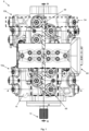
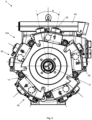
- Figures 1 and 2 show top and end views respectively of a hydraulic machine assembly 8 according to an embodiment of the invention.
- the assembly 8 comprises two individual ECMs, specifically ECPs 10, that are coupled together both fluidly and mechanically to form the assembly 8, which therefore defines a double machine.
- ECPs 10 the lowermost ECP defines a first ECP 10a and the uppermost ECP defines a second ECP 10b.
- the ECPs 10 are substantially identical to one another in this example and are arranged back-to-back, in that the ECPs 10 are coupled with mutually reverse orientations.
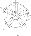
- Figure 3 shows a transverse cross section taken through the first ECP 10a, specifically through the line A-A in Figure 1 .
- the first ECP 10a includes a machine shaft defining a first driveshaft 12, which is driven by a prime mover (not shown) such as an internal combustion engine or an electric motor, for example.
- the driveshaft 12 couples to the prime mover via an axially protruding end portion 13 of the driveshaft 12, which is visible at the bottom of the assembly 8 in Figure 1 .
- the end portion 13 is enlarged and splined to facilitate coupling to the prime mover in this example.
- the second ECP 10b comprises a second driveshaft that is coaxial with and coupled to, and therefore driven by, the first driveshaft 12, such that rotation of the first driveshaft 12 is coupled to rotation of the second driveshaft. Coupling between the driveshafts may be effected in any suitable way, for example using a splined male-female interface or mechanical fixings.
- Providing a respective driveshaft 12 for each ECP 10, as in this embodiment eases assembly of the ECPs 10 by allowing each driveshaft 12 to be aligned with its associated PCUs in each ECP 10, before coupling the ECPs 10 and their associated driveshafts 12 together.
- the first and second driveshafts are mutually offset, which contributes to the creation of equiphased PCUs.
- the first driveshaft 12 is housed within a crankcase that defines a housing 14 of the ECP 10, the housing 14 having a circular cross-section in Figure 3 .
- the first driveshaft 12 has a central axis defining a shaft axis that is common to the first and second driveshafts, and which is aligned with the centre of the housing 14 in this example.
- the first driveshaft 12 carries a set of three eccentric cams 16 arranged in axial series along the first driveshaft 12, one of which cams is visible in Figure 3 , which may be fixed to or integral with the driveshaft 12.
- the respective eccentricities of the second and third cams, which are not visible in Figure 3 are arranged such that the three cams 16 are mutually offset and so have different phases, as explained further later.
- the second driveshaft carries a similar set of eccentric cams.
- each ECP 10 comprises three such banks 54 of PCUs 18, the banks 54 of each ECP 10 being axially-spaced at regular intervals so that the PCUs 18 of each bank 54 engage a respective one of the cams 16 of the associated driveshaft 12.
- each PCU 18 has a longitudinal axis defining a cylinder axis 20 that extends radially within the housing 14, the respective cylinder axes 20 of the PCUs 18 of the bank extending in a common plane that is orthogonal to the shaft axis.
- the PCUs 18 are equiangularly spaced around the driveshaft 12, and hence their respective cylinder axes 20 are spaced at 72° intervals around the shaft axis.
- the uppermost PCU 18 shown in Figure 3 aligns with the vertical and so is designated as 0° for illustrative purposes, although Figure 2 shows that the ECP 10 is actually oriented slightly differently.
- Each PCU 18 comprises a piston slipper 22 that engages a tubular outer face of the cam 16 to form a running interface with the cam 16 and therefore act as a cam follower.
- the eccentricity of the cam 16 causes the cam 16 to drive the PCUs 18 in angular succession, via their respective piston slippers 22.
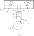
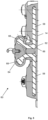
- FIG. 4 shows an individual PCU 18 in more detail.
- the PCU 18 comprises a piston 24 received within a cylinder 26, defining a working chamber 28 therebetween.
- a piston rod 30 extends towards the cam 16, a distal end of the piston rod 30 carrying or defining the piston slipper 22 that engages the cam 16.
- Reciprocating movement of the piston slipper 22 as the cam 16 rotates during pumping drives corresponding linear reciprocating movement of the piston 24 relative to and within the cylinder 26, causing pressurisation of hydraulic fluid in the working chamber 28.
- the working chamber 28 comprises two fluid ports, namely a low-pressure port 32 and a high-pressure port 34. Hydraulic fluid is drawn into the working chamber 28 through the low-pressure port 32 at relatively low pressure, for example from a low-pressure manifold. The hydraulic fluid is then pressurised and discharged from the working chamber 28 at elevated pressure through the high-pressure port 34 into a high-pressure manifold that is described later.
- the low-pressure port 32 therefore defines an inlet of the PCU 18 and the high-pressure port 34 defines an outlet of the PCU 18.
- the valve arrangement 36 includes a low-pressure valve (LPV) 38 that acts to open and close the low-pressure port 32, and a high-pressure valve (HPV) 40 that acts to open and close the high-pressure port 34.
- LBV low-pressure valve
- HPV high-pressure valve
- the LPV 38 opens while the piston 24 undergoes a filling or intake stroke, corresponding to downward movement in Figure 4 , and closes as the piston 24 undergoes a pumping stroke to displace the hydraulic fluid at elevated pressure, corresponding to upward movement in Figure 4 .
- the HPV 40 operates in a complementary manner and so opens during the pumping stroke to permit the pressurised fluid to be discharged, and closes during the intake stroke.
- the LPV 38 is shown schematically in Figure 4 , in a left portion of the valve arrangement 36.
- the LPV 38 is configured as a face-sealing poppet valve that acts as a check valve.
- the LPV 38 comprises a valve member defining a low-pressure poppet (LPP) 42, which is configured to engage a low-pressure valve seat 44 to close the low-pressure port 32 when required, and correspondingly to lift from the low-pressure valve seat 44 to open the low-pressure port 32.
- the LPP 42 is biased away from the low-pressure valve seat 44 by an LPV return spring 46, and so the LPV 38 is configured as a normally-open valve.
- the LPV 38 is configured to be normally open, and is thus open during intake strokes, primarily under the action of a spring force provided by the LPV return spring 46.
- a spring force provided by the LPV return spring 46.
- hydrodynamic forces acting on the LPP 42 generally align and compound with the respective spring force.
- Closing movement of the LPV 38 is controlled by a solenoid actuator, for example.
- the LPV 38 can therefore be closed selectively, enabling the volume of fluid admitted to the working chamber 28 on each cycle to be regulated. This, in turn, controls the extent to which the fluid is pressurised in each pumping stroke. Accordingly, the output of the PCU 18 is independently controllable from the output of other PCUs.
- the HPV 40 is shown to the right of the valve arrangement 36 in Figure 4 , and is also configured as a face-sealing poppet valve that acts as a check valve.
- the HPV 40 therefore comprises a high-pressure valve member defining a high-pressure poppet (HPP) 48.
- the HPP 48 is configured to engage a high-pressure valve seat 50 to close the high-pressure port 34 when required, and correspondingly to lift from the high-pressure valve seat 50 to open the high-pressure port 34.
- the HPP 48 is biased into engagement with the high-pressure valve seat 50 by an HPV return spring 52, and so the HPV 40 is configured as a normally-closed valve.
- the HPP 48 is on an opposite side of its valve seat 50 to the working chamber 28, and so the HPV 40 is configured to open passively during pumping strokes when the fluid pressure in the working chamber 28 overcomes the opposing force provided both by the spring force of the HPV return spring 50, and the pressure force acting on the other side of the HPP 48 connected to the high-pressure manifold, to allow high-pressure fluid to be discharged.
- the HPV 40 may also be solenoid-actuated to enable the HPV 40 to be opened selectively.
- each ECP 10 includes fifteen PCUs 18 in total, which as noted above are arranged in three axially-spaced banks 54 of five PCUs 18 each, the PCUs 18 of each bank 54 forming a circular array around, and being in driving engagement with, a respective cam 16 of the associated driveshaft 12.
- the overall assembly 8 therefore has thirty PCUs 18 in total, arranged in six banks 54 spaced along the shaft axis.
- FIG. 1 and 2 make clear that the PCUs 18 of the upper and lower banks 54 have the same orientations, such that each PCU 18 of the upper bank is circumferentially aligned with a PCU 18 of the lower bank, the respective cylinder axes 20 of the aligned PCUs 18 being at the same angle relative to the shaft axis.
- the middle bank 54 is rotated slightly relative to the upper and lower banks 54, such that the PCUs 18 of the middle bank are circumferentially offset from those of the upper and lower banks 54.
- the respective cylinder axes 20 of the PCUs 18 are therefore angularly spaced around the shaft axis by an angle represented as angle 'A' in Figure 2 , which is approximately 24° in this example. Offsetting the middle bank 54 in this way allows the axial spacing between the banks 54 to be reduced and thus promotes a compact configuration.
- the PCUs 18 of each ECP 10 are also arranged in groups of three to define triplets, each triplet including one PCU 18 from each bank 54 of the corresponding ECP 10, so that each PCU 18 of a triplet engages a different cam 16 of the associated driveshaft 12.
- the PCUs 18 of each triplet are arranged at similar circumferential positions with respect to the associated shaft axis, so that the respective high-pressure ports 34 of the PCUs 18 of a triplet form a substantially equilateral triangle, due to the circumferential offset of the PCU 18 of the middle bank 54. Accordingly, the respective piston slippers 22 of the triplet each engage their corresponding cam 16 at similar angular positions relative to the driveshaft 12.
- the eccentricities of the cams 16 are mutually offset.
- This offset is configured such that the PCUs 18 of a triplet are phased at 120° intervals.
- This entails a 120° offset between the upper and lower cams 16, and a slightly different offset for the middle cam 16, specifically 96° in this example, to account for the offset of 24° in the circumferential position of the PCU 18 of the middle bank 54. In this way, the PCUs 18 of a triplet are equiphased.
- the PCUs 18 of each triplet are fluidly coupled to define a pump module 56 of the associated ECP 10, so that each ECP 10 has a set of five pump modules 56, one of which is designated by a generally square dashed box in Figure 1 . It follows that the double machine defined by the machine assembly 8 has ten pump modules 56, each providing an independently-operable outlet.
- the high-pressure ports 32 of the PCUs 18 belonging to a pump module 56 are ganged, in that the fluid displaced by the PCUs 18 is combined.
- the PCUs 18 of each pump module 56 displace fluid into a respective common high-pressure manifold, or 'gallery' 58.
- Each gallery 58 is defined by a straight passage formed as a drilling in the housing 14 of the ECP 10, each drilling extending parallel to the shaft axis. Such drillings are advantageously relatively straightforward to manufacture.
- Each gallery 58 is in fluid communication with the respective high-pressure ports 32 of the associated PCUs 18, and is situated halfway between the cylinder axes 20 of those PCUs 18, extending from an axial position corresponding to the outermost PCU 18 towards the axial centre of the assembly 8.
- each ECP 10 has a set of five mutually parallel galleries 58 that are equi-angularly spaced around the shaft axis, each handling the output of a respective pump module 56.
- the constituent PCUs 18 of each pump module 56 are configured to operate out-of-phase with each other due to the offset eccentricities of the associated driving cams 16, such that the respective phases are evenly spread over the 360° range of the driveshaft 12. This reduces ripple in the output from the pump module 56 in operation.
- the PCUs 18 of each bank 54 are also equiphased due to the regular angular spacing of the PCUs 18 around the associated driving cam 16. In consequence, in this example all of the PCUs 18 of each ECP 10 are out-of-phase with one another, and indeed are equiphased.
- This principle can be generalised, in that equiphasing between all PCUs of an ECM having a similar topology to the present example, and between the respective PCUs of each machine module of the ECM, can be achieved if the number of banks of PCUs is coprime with the number of PCUs in each bank, that is, these two values have no common factors other than one.
- This principle can be extended to the overall assembly 8 defined by the double machine, in that equiphasing is possible for the assembly 8 as a whole since the total number of banks 54 is coprime with the number of PCUs 18 in each bank, which values are six and five respectively in this example. If the machines are identical and so have the same number of banks each, it follows that each bank must have an odd number of PCUs to satisfy this coprime requirement.
- the first and second ECPs 10 are coupled end-to-end with reverse orientations, which is evident from the respective orientations of the triangles formed by the triplets of each ECP 10 in Figure 1 .
- This may be referred to as the ECPs 10 being coupled 'back-to-back'. Accordingly, the ECPs 10 are not in mirror relation to each other.
- the ECPs 10 are coupled with matching circumferential orientations, such that each pump module 56 is circumferentially aligned with a corresponding pump module 56 of the other ECP 10, defining a pair of adjacent pump modules 56.
- the respective high-pressure galleries 58 of each pair of pump modules 56 are circumferentially aligned and are thus coaxial.
- Each pair of aligned galleries 58 are fluidly connected, thereby ganging the associated pump modules 56 to form hexlets comprising three PCUs 18 from each ECP 10.
- the machine assembly 8 further comprises a ganging block 60 disposed between the first and second ECPs 10, the ganging block 60 being configured to connect each pair of aligned galleries 58, and therefore the associated pump modules 56, to form the hexlets in a selective manner.
- the ganging block 60 therefore acts as a module connector.
- the ganging block 60 also defines a pair of outlet ports for the assembly 8.
- the ganging block 60 is embodied as an assembly that is divided into an intermediate block 62 and a top ganging block 64 that is radially outward of the intermediate ganging block 62.
- the intermediate ganging block 62 is disposed between the respective housings 14 of the ECPs 10, and includes intermediate passages 66 defining openings that align with corresponding exit openings of each gallery 58. These intermediate passages 66 turn through a right angle to extend radially and connect with corresponding output lines 68 in the top ganging block 64.
- the output lines 68 can then be connected to one another or to output lines associated with other galleries 58, either selectively or permanently, in any suitable way.
- Figure 6 provides a similar cross sectional view to Figure 5 of a variant of the ganging block 160, which may also be implemented in the assembly 8 of Figure 1 .
- the ganging block variant 160 shown in Figure 6 has the same intermediate ganging block 62 as the variant of Figure 5 , although the portion of the intermediate ganging block 62 including the galleries 58 is hidden in Figure 6 .
- the top ganging block 164 is different to that of Figure 5 .
- the top ganging block 164 includes a valve arrangement 70, the valve arrangement 70 being configured to connect a pair of intermediate passages 66 visible at the bottom of Figure 6 selectively to either one of a pair of output lines of the ganging block 160, namely a first output line 72 and a second output line 74.
- the first output line 72 connects to a first output port (not shown) of the ganging block 160
- the second output line 74 connects to a second output port (not shown) of the ganging block 160, the first and second output ports defining the output ports of the assembly 8.
- the first output line 72 is divided into two branches, namely a first branch 72a shown to the left in Figure 6 and a second branch 72b shown to the right.
- the second output line 74 extends between the first and second branches 72a, 72b.
- the output lines 72, 74 extend orthogonally to the plane of the cross section in Figure 6 , and so appear as a row of three openings extending across an upper portion of the top ganging block 164 in Figure 6 .
- the valve arrangement 70 includes a pair of two-way spool valves 76, each of which is associated with a respective one of the intermediate passages 66.
- Each spool valve 76 is operable to connect its respective intermediate passage 66 to either one of the output lines 72, 74.
- the branching of the first output line 72 facilitates this, in that the intermediate passage 66 shown on the left in Figure 6 can be connected to the first branch 72a, and correspondingly the intermediate passage 66 shown on the right in Figure 6 can be connected to the second branch 72b.
- the spool valves 76 may be conventional in construction and so are not shown or described in detail in the interests of clarity.
- the valve arrangement 70 further includes a row of four check valves 78, which act to prevent cross flow between the output lines 72, 74 when the spool valves 76 are switching positions.
- the check valves 78 may be conventional.
- valve arrangement 70 is operable to connect each of the associated intermediate passages 66, and in turn the corresponding pump modules 56, to either one of the output ports of the assembly in a selective manner.
- the ganging block 160 includes a respective valve arrangement 70 for each pair of intermediate passages 66 and the associated pump modules 56 of the assembly 8. Accordingly, the valve arrangements 70 collectively enable any pump module 56 to be fluidly coupled to either one of the output ports of the assembly 8. This creates a wide range of possible operating states for the assembly 8 and thus enhances flexibility in the flow that can be delivered through each output port.
- the intermediate passages 66 or output lines 68 may be in permanent fluid communication, such that the associated galleries 58 and pump modules 56 are permanently ganged as hexlets.
- the valve arrangement 70 shown in Figure 6 is purely an example, and various other ganging arrangements may be used. It is also possible for the ganging block 60, 160 to be omitted, and for ganging of the pump modules 56 to take place externally of the assembly 8.
- the respective driveshafts 12 of the first and second ECPs 10 are coupled with an angular offset, so that the respective sets of cams 16 of each driveshaft 12 are out-of-phase with one another.
- the cams 16 of the driveshafts 12 are set such that their respective phases are interleaved and at regular intervals of approximately 60°, accounting for the adjustment of each middle cam 16 due to the circumferential offset of the corresponding PCUs 18 of the middle bank 54 of each ECP 10.
- the cams 16 are offset at 84° intervals in this example, so that the phases of the PCUs 18 are at regular 12° intervals.
- phase of a PCU 18 is dependent on both the phase of the cam 16 that drives the PCU 18 and the angular position of the PCU 18 with respect to the cam 16. Accordingly, adjusting the phases of the cams 16 of the second driveshaft relative to the cams 16 of the first driveshaft 12 creates a corresponding adjustment in the phases of the PCUs 18 of both the banks 54 and the pump modules 56 of the second ECP 10b.
- the PCUs 18 of the entire assembly are equiphased, the phases of the respective PCUs 18 of each ECP 10 being interleaved.
- the phases of the PCUs 18 of each hexlet are also equiphased.
- Offset hexlets equispaced A + 360 2 N PCUs module + 360 N PCUs module i ⁇ 1 in which:
- the above formula indicates possible offset values of 84°, 204° or 324° between the driveshafts 12 of the first and second ECPs 10 to achieve equiphased PCUs 18 in each hexlet.
- equiphased hexlets are desired, with one machine module belonging to one ECP and one machine module belonging the other ECP, but not necessarily equiphased PCUs throughout the assembly, one way to provide for this is by ensuring that the number of banks of each individual machine is coprime with the number of PCUs in each bank.
- an assembly composed of two machines each having three banks of four PCUs can be configured to create equiphased hexlets by introducing an offset of 60°, or a multiple of 60°, between the cams of the assembly.
- pump modules 56 may be ganging and operated in two notional groups that together form a 'service pumplet'.
- a first group which may be referred to as a ⁇ modulating pumplet', may comprise a hexlet, while the second group is composed of one or more other pump modules 56 and may be referred to as an ⁇ offset pumplet'.
- the ganging block 60, 160 connects the pump modules 56 of the modulating pumplet and the offset pumplet to one of the output ports of the assembly 8, thereby defining a service pumplet flow.
- the characteristics of the service pumplet flow can be regulated by controlling the modulating pumplet and the offset pumplet in different ways to one another, in the sense that each pumplet provides a different flow, whilst ensuring that the combined flow from the modulating and offset pumplets meets the present demand.
- the PCUs 18 associated with the offset pumplet may always be active, albeit not necessarily operating at full stroke, while the modulating pumplet is modulated to vary the overall service pumplet flow.
- modulating the modulating pumplet entails operating the LPVs 38 of the associated PCUs 18 to regulate the quantity of fluid that is displaced by each PCU 18 on each cycle.
- each PCU 18 of the modulating pumplet may displace a different quantity of fluid, although it may be preferred for all PCUs 18 of the modulating pumplet to deliver the same flow for a steady output.
- PCUs 18 of the modulating pumplet in sub groups, for example to control a first group composed of alternate PCUs 18, with respect to the PCU phasing, to deliver a different flow to the remaining PCUs 18 forming a second group, the first and second groups therefore being interleaved.
- Varying the service pumplet flow primarily through modulating an equispaced hexlet promotes sustained steady and low ripple flow from the service pumplet while the flow rate alters to meeting changing demands.
- the ganging block could be implemented in various different ways.
- separate ganging blocks are used for each hexlet. It is also possible for ganging to take place in the intermediate ganging block, which may also be integral with the top ganging block.
- the common driveshaft includes a respective set of cams for each machine, those sets of cams being mutually offset to achieve the same effect as the separate driveshafts of the above example.
- a pair of machines may be arranged back-to-front or front-to-front, and not back-to-back as in the embodiment described above.
- the machines may exhibit a generally mirror relation to one another.
- the high-pressure galleries of a hexlet may not be coaxial in such an arrangement, in which case the ganging block can be updated accordingly to accommodate the altered fluid connections.
Landscapes
- Engineering & Computer Science (AREA)
- Mechanical Engineering (AREA)
- General Engineering & Computer Science (AREA)
- Chemical & Material Sciences (AREA)
- Combustion & Propulsion (AREA)
- Reciprocating Pumps (AREA)
- Hydraulic Motors (AREA)
Priority Applications (5)
| Application Number | Priority Date | Filing Date | Title |
|---|---|---|---|
| EP23152781.3A EP4403764A1 (fr) | 2023-01-20 | 2023-01-20 | Machine hydraulique |
| PCT/EP2024/051322 WO2024153817A1 (fr) | 2023-01-20 | 2024-01-19 | Machine hydraulique |
| EP24704088.4A EP4652367A1 (fr) | 2023-01-20 | 2024-01-19 | Machine hydraulique |
| JP2025541654A JP2026509624A (ja) | 2023-01-20 | 2024-01-19 | 油圧機械 |
| CN202480005554.2A CN120435619A (zh) | 2023-01-20 | 2024-01-19 | 液压机器 |
Applications Claiming Priority (1)
| Application Number | Priority Date | Filing Date | Title |
|---|---|---|---|
| EP23152781.3A EP4403764A1 (fr) | 2023-01-20 | 2023-01-20 | Machine hydraulique |
Publications (1)
| Publication Number | Publication Date |
|---|---|
| EP4403764A1 true EP4403764A1 (fr) | 2024-07-24 |
Family
ID=85018593
Family Applications (2)
| Application Number | Title | Priority Date | Filing Date |
|---|---|---|---|
| EP23152781.3A Withdrawn EP4403764A1 (fr) | 2023-01-20 | 2023-01-20 | Machine hydraulique |
| EP24704088.4A Pending EP4652367A1 (fr) | 2023-01-20 | 2024-01-19 | Machine hydraulique |
Family Applications After (1)
| Application Number | Title | Priority Date | Filing Date |
|---|---|---|---|
| EP24704088.4A Pending EP4652367A1 (fr) | 2023-01-20 | 2024-01-19 | Machine hydraulique |
Country Status (4)
| Country | Link |
|---|---|
| EP (2) | EP4403764A1 (fr) |
| JP (1) | JP2026509624A (fr) |
| CN (1) | CN120435619A (fr) |
| WO (1) | WO2024153817A1 (fr) |
Citations (3)
| Publication number | Priority date | Publication date | Assignee | Title |
|---|---|---|---|---|
| JPS508130B1 (fr) * | 1970-02-21 | 1975-04-02 | ||
| EP0069462A2 (fr) * | 1981-06-09 | 1983-01-12 | MacTAGGART SCOTT & COMPANY LIMITED | Pompe ou moteur hydraulique |
| US20170276123A1 (en) * | 2014-09-11 | 2017-09-28 | Hermetik Hydraulik Ab | Displacing device |
-
2023
- 2023-01-20 EP EP23152781.3A patent/EP4403764A1/fr not_active Withdrawn
-
2024
- 2024-01-19 WO PCT/EP2024/051322 patent/WO2024153817A1/fr not_active Ceased
- 2024-01-19 JP JP2025541654A patent/JP2026509624A/ja active Pending
- 2024-01-19 CN CN202480005554.2A patent/CN120435619A/zh active Pending
- 2024-01-19 EP EP24704088.4A patent/EP4652367A1/fr active Pending
Patent Citations (3)
| Publication number | Priority date | Publication date | Assignee | Title |
|---|---|---|---|---|
| JPS508130B1 (fr) * | 1970-02-21 | 1975-04-02 | ||
| EP0069462A2 (fr) * | 1981-06-09 | 1983-01-12 | MacTAGGART SCOTT & COMPANY LIMITED | Pompe ou moteur hydraulique |
| US20170276123A1 (en) * | 2014-09-11 | 2017-09-28 | Hermetik Hydraulik Ab | Displacing device |
Also Published As
| Publication number | Publication date |
|---|---|
| CN120435619A (zh) | 2025-08-05 |
| JP2026509624A (ja) | 2026-03-23 |
| EP4652367A1 (fr) | 2025-11-26 |
| WO2024153817A1 (fr) | 2024-07-25 |
Similar Documents
| Publication | Publication Date | Title |
|---|---|---|
| JP6808616B2 (ja) | 油圧ポンプ用のコントローラ | |
| US4016719A (en) | Hydrostatic transmission system | |
| US11994121B1 (en) | Piston in piston variable displacement hydraulic device | |
| JPH09511818A (ja) | 連続可変水圧トランスミッション | |
| US20010022171A1 (en) | Pump for supplying a fuel injection system and for supplying a hydraulic valve controller for internal combustion engines | |
| EP4403764A1 (fr) | Machine hydraulique | |
| US8347778B2 (en) | Fluid-working machines | |
| EP2933485B1 (fr) | Pompe hydraulique à écoulement de fluide variable | |
| JP6501415B2 (ja) | 静油圧アセンブリ | |
| US5167181A (en) | Fluid transfer devices | |
| CN102422021A (zh) | 活塞机,尤其是液体活塞机 | |
| JP4177406B2 (ja) | 燃料供給装置 | |
| US20170159641A1 (en) | Variable displacement pump-motor | |
| US6183207B1 (en) | Digital pump | |
| US20090120278A1 (en) | Electrohydrostatic actuator including a four-port, dual displacement hydraulic pump | |
| US11946468B2 (en) | Hydraulic machine with controllable valves and method for idling such a hydraulic machine | |
| EP4202233A1 (fr) | Ensemble distributeur à tiroir | |
| EP3775547B1 (fr) | Homogénéisateur haute pression | |
| EP4202232A1 (fr) | Système hydraulique | |
| US20090031892A1 (en) | Hydrostatic piston machine according to the floating cup concept | |
| WO2010053521A1 (fr) | Machine a circuits multiples et piston axial | |
| WO2012031584A2 (fr) | Machine à pistons commandée par soupape et procédé pour faire fonctionner une machine à pistons commandée par soupape | |
| JP2000009024A (ja) | 可変容量形ピストンポンプ | |
| US20220403857A1 (en) | Multi-control valve unit | |
| JPH10184532A (ja) | 可変容量形ピストンポンプ |
Legal Events
| Date | Code | Title | Description |
|---|---|---|---|
| PUAI | Public reference made under article 153(3) epc to a published international application that has entered the european phase |
Free format text: ORIGINAL CODE: 0009012 |
|
| STAA | Information on the status of an ep patent application or granted ep patent |
Free format text: STATUS: THE APPLICATION HAS BEEN PUBLISHED |
|
| AK | Designated contracting states |
Kind code of ref document: A1 Designated state(s): AL AT BE BG CH CY CZ DE DK EE ES FI FR GB GR HR HU IE IS IT LI LT LU LV MC ME MK MT NL NO PL PT RO RS SE SI SK SM TR |
|
| STAA | Information on the status of an ep patent application or granted ep patent |
Free format text: STATUS: THE APPLICATION IS DEEMED TO BE WITHDRAWN |
|
| 18D | Application deemed to be withdrawn |
Effective date: 20250125 |