EP4403752A1 - System und verfahren zur erzeugung von elektrischer energie - Google Patents
System und verfahren zur erzeugung von elektrischer energie Download PDFInfo
- Publication number
- EP4403752A1 EP4403752A1 EP23152785.4A EP23152785A EP4403752A1 EP 4403752 A1 EP4403752 A1 EP 4403752A1 EP 23152785 A EP23152785 A EP 23152785A EP 4403752 A1 EP4403752 A1 EP 4403752A1
- Authority
- EP
- European Patent Office
- Prior art keywords
- circuit
- branch
- transfer fluid
- heat transfer
- energy
- Prior art date
- Legal status (The legal status is an assumption and is not a legal conclusion. Google has not performed a legal analysis and makes no representation as to the accuracy of the status listed.)
- Withdrawn
Links
Images
Classifications
-
- F—MECHANICAL ENGINEERING; LIGHTING; HEATING; WEAPONS; BLASTING
- F01—MACHINES OR ENGINES IN GENERAL; ENGINE PLANTS IN GENERAL; STEAM ENGINES
- F01K—STEAM ENGINE PLANTS; STEAM ACCUMULATORS; ENGINE PLANTS NOT OTHERWISE PROVIDED FOR; ENGINES USING SPECIAL WORKING FLUIDS OR CYCLES
- F01K17/00—Using steam or condensate extracted or exhausted from steam engine plant
- F01K17/005—Using steam or condensate extracted or exhausted from steam engine plant by means of a heat pump
-
- F—MECHANICAL ENGINEERING; LIGHTING; HEATING; WEAPONS; BLASTING
- F01—MACHINES OR ENGINES IN GENERAL; ENGINE PLANTS IN GENERAL; STEAM ENGINES
- F01K—STEAM ENGINE PLANTS; STEAM ACCUMULATORS; ENGINE PLANTS NOT OTHERWISE PROVIDED FOR; ENGINES USING SPECIAL WORKING FLUIDS OR CYCLES
- F01K17/00—Using steam or condensate extracted or exhausted from steam engine plant
- F01K17/02—Using steam or condensate extracted or exhausted from steam engine plant for heating purposes, e.g. industrial, domestic
Definitions
- the present invention relates to the field of energy generation, in particular the cogeneration of electrical and/or mechanical energy and thermal energy.
- Mechanical energy can be converted into electrical energy, this mechanical energy being generated from a thermal energy transport and distribution network.
- This thermal energy can for example be energy used in particular for heating buildings, heating domestic hot water, air conditioning buildings, refrigeration and/or freezing.
- this invention relates to an electrical energy generation system comprising a thermal energy transport and distribution circuit, a cogeneration circuit materially connected to the thermal energy transport and distribution circuit and a thermally connected user circuit said cogeneration circuit.
- thermo energy transmission and distribution systems connected to one or more energy sources, generally called hot sources, from which energy is taken.
- This energy is then transmitted to a heat transfer fluid, for example by means of heat exchangers, these heat exchangers allowing a transfer of thermal energy between the hot source and the heat transfer fluid without exchange of material.
- the heat transfer fluid is circulated in a distribution circuit.
- Energy consumers or user circuits can be connected to this distribution circuit, for example also by means of heat exchangers. Thermal energy can thus be exchanged between the distribution circuit and the user circuit or the consumers, whether from the distribution circuit to a user circuit or, on the contrary, from a user circuit to the distribution circuit.
- Such energy distribution systems are often used as district heating, primarily to heat homes or buildings in general. In reversible systems, it is also possible to produce conditioned air or more generally, cold for air conditioning or refrigeration.
- CO 2 carbon dioxide
- CO 2 is interesting in particular because at the temperatures in which it is generally used, it does not go into a solid state, unlike water in particular. It is therefore not necessary to take special precautions to prevent it from assuming this state of matter.
- by choosing an appropriate combination of pressure and temperature it is possible to use the phase transition between the gaseous state and the liquid state of carbon dioxide. This phase transition allows a release or capture of a large amount of energy without a change in temperature.
- the quantity of energy per unit of volume is much greater in the case where this energy comes from a change in phase between liquid CO 2 and gaseous CO 2 only in the case where it comes from a change in water temperature.
- the diameter of the tubes in which the heat transfer fluid circulates may be significantly smaller in the case where this heat transfer fluid is CO 2 than in the case where it is water. This results in particular in a simplified installation.
- the energy transport and distribution system comprises a circuit formed of two branches.
- the heat transfer fluid consisting of carbon dioxide circulating in one of the branches is in the gaseous state, while it is in the liquid state in the other branch of the circuit. Energy transfer is achieved by phase change from the gas state to the liquid state and vice versa.
- This document describes an energy distribution system in particular intended for air conditioning or air conditioning installations, the temperature of which is typically between 18°C and 25°C, for refrigeration installations, with a temperature generally between 1°C and 6°C, for domestic heating installations, with temperatures for example between 30°C and 35°C and for domestic hot water heating installations, with a temperature generally between 10°C and 60°C.
- the heat transfer fluid provides energy to the consumer or it takes energy from the consumer.
- the energy from energy sources is greater than the energy needed by consumers.
- This surplus energy is therefore available in particular for storage and/or transfer to other consumers or other networks.
- This energy is in principle thermal energy.
- the storage as well as the transport of this type of energy can pose a certain number of problems and require complex and expensive infrastructure. There is therefore a need to be able to convert, store and/or transport surplus energy, so as to be able to use it when energy demand is greater than available energy.
- the present invention makes it possible to resolve the problems mentioned above by proposing a cogeneration system arranged to generate thermal energy in a form usable by consumers on the one hand and electrical energy on the other hand, in a energy transport and distribution network. Furthermore, this cogeneration system makes it possible to balance energy demand with the quantity of available energy, very flexibly and very quickly, while offering good efficiency, in particular by reducing wasted energy.
- the amount of electrical energy generated can be adapted according to electrical energy requirements, thermal energy requirements and available primary energy resources. In particular, when thermal energy requirements are less than available energy, excess energy can be converted into electrical energy, allowing efficient transfer of this energy to other consumers or storage and subsequent use of this energy.
- the system of the invention makes it possible to recover energy from sources which are often not used because their physical characteristics do not correspond to the needs of existing installations .
- sources can be for example cooling water from industrial installations, return liquid from heating to distance, thermal energy from photovoltaic panels or other types of energy sources generally considered unusable.
- conventional energy sources in particular electrical energy from photovoltaic panels, hot water from the “flow” liquid of district heating, or thermal energy from thermal solar panels.
- This recovered energy can then be used as input in a circuit in which carbon dioxide used as a heat transfer fluid circulates.
- This circuit comprises at least one branch, called the hot branch, in which the carbon dioxide circulates in gaseous form and one branch, called the cold branch, in which the heat transfer fluid circulates in liquid form.
- These two branches are connected together by at least one device making it possible to modify the state of the heat transfer fluid, this state being liquid or gaseous. It is clear that during the transition from one state to another, a mixture is formed and the heat transfer fluid can contain a part of carbon dioxide in gaseous form and a part in liquid form.
- the system of the invention further comprises a branch making it possible to adapt the energy needs or demands in relation to the available energy, which allows the entire system to operate optimally. Furthermore, the surplus energy, namely the available energy which is not used, can in particular be converted into mechanical energy, which itself can be converted into electrical energy by means of a turbine. This electrical energy can be stored in particular in batteries or supercapacitors for later use or transmitted remotely, for use in a place other than the place of production.
- the temperature differences between the hot branch and the cold branch can be chosen so as to be relatively small, in particular due to the high specific enthalpy of carbon dioxide.
- the temperature of the hot branch and the cold branch can be close to the temperature of the terrestrial register at shallow depth, typically between 1 m and 2 m.
- the heat transfer fluid can be constantly circulated. Due to the small temperature difference between the branches of the circuit and the ground register, and the continuous circulation of the heat transfer fluid, there is little energy loss between the branches of the circuit and the ground. This means in particular that it is not necessary to insulate the tubes forming the branches in which the heat transfer fluid circulates. This simplifies installation and reduces costs for the entire system.
- the system of the invention is also interesting in that it makes it possible to form circuit portions, these portions being able to be independent of each other or, on the contrary, to be connected to each other.
- This connected or independent aspect of the circuit portions can be modified automatically, depending on the needs and resources of each portion.
- the electrical energy produced by cogeneration can be used to power another portion of a circuit or another circuit when this circuit or this portion of a circuit consumes more energy than what the primary energy sources can provide. This therefore allows great flexibility and dynamic adaptation of the system.
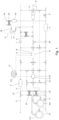
- the electrical energy generation system 10 operates in an energy transport and distribution network.
- the latter comprises at least one circuit 11 in which a heat transfer fluid circulates.
- the heat transfer fluid comprises carbon dioxide.
- This carbon dioxide is particularly interesting in that it is capable of undergoing a phase transition between the liquid state and the gaseous state at temperatures and pressures achievable in practice in technically feasible installations. Furthermore, at these temperatures and pressures, it does not undergo a phase change towards the solid state, which would make the system unusable.
- the quantity of energy exchanged per unit mass of carbon dioxide, or specific enthalpy is large, which implies that it is possible to transfer or transport a large quantity of energy for a small volume.
- Circuit 11 of the invention comprises at least three branches.
- One of the branches, called the hot branch 12 contains carbon dioxide CO 2 in the gaseous state.
- the temperature of the gas in this hot branch can be higher than 12°C, for example around 15°C and preferably between 15°C and 60°C. Please note that this temperature is indicative. Indeed, it can vary depending on several parameters, in particular the type of energy consumers connected to the circuit and their specific needs, the type of energy sources available and their characteristics which themselves can vary depending on daily or seasonal cycles in particular, as well as the place where the measurements are taken in the circuit. Furthermore, the temperature can also vary over time depending on the energy taken or the energy received by the circuit.
- the pressure of the carbon dioxide in the hot branch 12 can be between 10 bars and 60 bars. Similar to temperature, the carbon dioxide pressure in the hot branch can also vary depending on where in that branch and when the measurement is made.
- the circuit includes a second branch, called cold branch 13, containing carbon dioxide in the liquid state.
- the temperature of the liquid CO 2 is also variable in the cold branch, particularly depending on the location in the branch.
- This temperature is, however, lower than the temperature of the gas in the hot branch 12.
- the temperature in the cold branch 13 can be lower than 15°C and for example be between 10°C and 12°C. .
- the energy transport and distribution network also includes a regulation branch 14. This is materially connected on the one hand to the hot branch 12 of the circuit and on the other hand to the cold branch 13 of this circuit.
- the role of the regulation branch 14 is to ensure the balancing of circuit 11 with regard to heat and refrigeration requirements. This material connection allows an exchange of material between the regulation branch 14 and the hot 12 and cold 13 branches.
- the regulation branch 14 can advantageously also be thermally connected to the cold branch 13 by means of at least one heat exchanger 8.
- the latter is arranged to transfer energy between the regulation branch 14 and the cold branch without material is not exchanged.
- the regulation branch 14 in principle contains a mixture of CO 2 in the gaseous state and in the liquid state, at constant temperature and pressure per zone of the regulation branch.
- the absorption or release of energy is achieved by changing the proportion of liquid CO 2 and gaseous CO 2 .
- the regulation branch 14 of the circuit 11 of the invention comprises at least one transformation device 15 whose function is to modify the temperature and/or pressure of the heat transfer fluid when the latter passes through this transformation device.
- the transformation device 15 can essentially take four distinct forms. According to a first form, this transformation device can include a compressor 16. The latter acts on the carbon dioxide in the gaseous state and has the effect of increasing the pressure in the gas. This increase in pressure also has the effect of increasing the temperature of the gas. The state of the gaseous carbon dioxide is not changed.
- the transformation device can include a regulator 17.
- the latter also acts on the carbon dioxide in the gaseous state and has the effect of reducing the pressure in the gas. This reduction in pressure has the effect of reducing the temperature of the heat transfer fluid.
- the state of gaseous carbon dioxide can be changed to a liquid state or, on the contrary, remain in a gaseous state.
- the transformation device can comprise a heating device 18.
- the latter can act on the carbon dioxide in the gaseous state and in the liquid state and increases the temperature of the heat transfer fluid. This increase in temperature, when applied to liquid carbon dioxide, can have the effect of generating a phase transition, from the liquid state to the gaseous state. Depending on the magnitude of the temperature increase, carbon dioxide may also remain in a liquid state or form a mixture of gas and liquid.
- the transformation device can comprise a cooling device 19.
- the latter can act on carbon dioxide in the gaseous state as well as on carbon dioxide in the liquid state. It reduces the temperature of the heat transfer fluid. This decrease in temperature, when applied to gaseous carbon dioxide, can have the effect of generating a phase transition, from the gas to the liquid state. Similar to heating, depending on the magnitude of the temperature decrease, carbon dioxide can also remain in a gaseous state or form a mixture of gas and liquid.
- the heating device 18 and the cooling device 19 have been illustrated by the same element.
- the compressor 16 and the expander 17 have been represented as two distinct elements. In practice, it is possible to use the same element for heating and cooling the heat transfer fluid or, on the contrary, two separate elements. Similarly, it is possible to use the same element to compress or expand the heat transfer fluid, or on the contrary to use two separate elements.
- a zone of the regulation branch 14 is defined as a part of this regulation branch between two consecutive transformation devices 15.
- the temperature, pressure and proportion of liquid carbon dioxide and gaseous carbon dioxide in one area of the control branch 14 are substantially the same throughout the area.
- the temperature, the pressure and/or the proportion of liquid carbon dioxide and gaseous carbon dioxide can, on the other hand, vary from one zone to another of the regulation branch 14.
- the pressure can be of the of around 45 bars and the temperature of around 10°C in an area.
- This temperature and this pressure may be the same or substantially the same in another zone of the regulation branch, the proportion of liquid carbon dioxide and gaseous carbon dioxide may be different in these two zones.
- this pressure can generally be between 15 and 100 bars, the transition temperature depending on this pressure.
- This pressure can be fixed over time or, on the contrary, be variable and adapted to the needs of the system, in particular depending on the time of day or year, so as to adapt the system dynamically to the needs of consumers. and available resources.
- the system of the invention may include, on certain branches and/or certain zones, a storage element 9 making it possible to manage the quantity of heat transfer fluid in the different locations of the circuit.
- a storage element 9 making it possible to manage the quantity of heat transfer fluid in the different locations of the circuit.
- the cold branch 13 may in particular comprise one or more pumps 7.
- the hot branch 12 may comprise one or more compressors or one or more valves, in particular anti-pressure valves. return and/or downstream pressure control valves 6.
- the compressor 16 of the regulation branch 14 has an input connected to the hot branch 12 of the circuit and/or to the regulation branch 14 of this circuit.
- An outlet of the compressor 16 is connected to the regulation branch 14 so that the compressed gas is introduced into this regulation branch.
- the carbon dioxide leaving the compressor 16 can be introduced into the hot branch 12, into the cold branch 13 or into the regulation branch 14 of the circuit.
- the quantity or proportion of carbon dioxide transferred to each of these branches may in particular depend on the energy requirements, the energy available and the quantities of liquid carbon dioxide and gaseous carbon dioxide contained in the mixture leaving the compressor 16 .
- This heating device 18 or cooling device 19 has an output which is also connected to the hot branch 12, to the cold branch 13 and to the regulation branch 14 of the circuit.
- liquid carbon dioxide, gaseous carbon dioxide and/or a mixture of carbon dioxide with gaseous and liquid state it is possible to choose the quantity of liquid carbon dioxide and carbon dioxide which emerges from the heating device 18 and the cooling device 19.
- Carbon dioxide Liquid can be introduced in whole or in part into the cold branch 13 of the circuit.
- the gaseous carbon dioxide can be introduced in whole or in part into the hot branch 12 of the circuit.
- the carbon dioxide which is not introduced into the corresponding branch of the circuit is kept in the regulation branch 14.
- the choice of the quantities or proportions which are directed towards each of the branches is carried out so that the circuit 11 is balanced in terms of demand and needs, so that this circuit is functional.
- valves 20 The connections between the different transformation devices and the different branches of the circuit are generally made by means of valves 20 or similar elements, making it possible to choose and adjust the quantities of each fluid which is diverted towards each branch of the circuit or towards each transformation device.
- These valves 20 are generally controlled automatically, depending on the needs of the entire circuit.
- the system 10 of the invention is connected to at least one primary energy source 21, for example water coming from a district heating return pipe. It should be noted that generally, the heat from this return duct is considered useless due to the fact that it contains the energy which was not taken by the district heating.
- Photovoltaic and/or thermal solar panels can also be used as a primary energy source.
- connection between the energy source(s) and one of the branches of the circuit of the system of the invention can be made by means of a heat exchanger 22 in the case where the energy source comes from a fluid such as water.
- a heat exchanger is interesting in that it allows a transfer of energy between two fluids, from the hot fluid to the cold fluid, without however there being an exchange of material.
- a heat exchanger may in particular be a plate exchanger.
- one of the primary energy sources produces electrical energy, this can be used directly to operate the components of the system which require electrical power. It can also be converted into thermal energy.
- three primary energy sources 21a, 21b, 21c are represented. Two of these energy sources contain energy in a fluid, specifically water. These energy sources are connected to a heat exchanger 22.
- one of the heat exchangers is connected to the hot branch 12 of the circuit, in which the carbon dioxide circulates in gaseous form and the The other heat exchanger is connected to the cold branch 13 of the circuit, in which the carbon dioxide circulates in liquid form.
- the third energy source 21c is a photovoltaic solar panel.
- the electricity produced by this panel can be used directly by the components of the system, in particular the transformation devices 15; it can be stored in the form of electricity in batteries or supercapacitors in particular; it can also be converted into thermal energy and stored for example in the terrestrial register. It could also be converted to be stored in fuel cells for example.
- Photovoltaic solar panels also produce thermal energy that usually goes unused.
- this thermal energy can be recovered for example by means of one or more heat exchangers (not shown) and also be used as an energy source.
- one of the energy sources (21a) can be an outlet conduit of a remote heating device and have a temperature between 70°C and 90°C.
- the other energy source (21b) can be a return conduit from the remote heating device and have a temperature between 25°C and 50°C.
- Carbon dioxide in the gaseous state can have a temperature greater than or equal to a value between 12°C and 15°C while carbon dioxide in the liquid state can have a temperature less than or equal to the temperature of the carbon dioxide in the gaseous state.
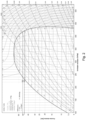
- the transition temperature between the liquid and gaseous states of carbon dioxide varies depending on the pressure.
- the carbon dioxide pressure as used in the invention can vary depending on the location of the circuit. It is generally between 10 bars and 60 bars.
- the pressure of the carbon dioxide can be of the order of 45 bars.
- the phase transition temperature of carbon dioxide is about 10°C at this pressure.
- the phase transition temperature as a function of pressure is visible on the figure 2 .
- the actual carbon dioxide pressure may be higher or lower than this value in certain areas of the circuit.
- This generation of electrical energy in the system of the invention is detailed below.
- This generation of electrical energy is carried out in a cogeneration circuit 23 thermally connected to a user circuit 24.
- This thermal connection between the cogeneration circuit 23 and the user circuit 24 is carried out for example by means of a heat exchanger 25 allowing to exchange energy between the two circuits without exchange of matter.
- the cogeneration circuit 23 contains heat transfer fluid like the rest of the energy transport and distribution circuit 11.
- the user circuit 24 contains a heat transfer fluid, here called user heat transfer fluid, which may be of the same nature as the heat transfer fluid of the cogeneration circuit 23 or which may be different. Typically, if the user circuit 24 is used for heating a building or for domestic hot water, this user heat transfer fluid may be water.
- the cogeneration circuit 23 comprises a compressor 26 having an inlet physically connected to the hot branch 12 and an output connected to an inlet of the heat exchanger 25.
- This compressor 26 has the function of taking hot heat transfer fluid from the hot branch 12 and compress this gas so as to raise its temperature.
- the temperature of the carbon dioxide gas leaving the compressor 26 must be compatible with the needs of the user circuit 24.
- the thermal energy of the carbon dioxide gas entering the heat exchanger 25 must be sufficient to heat the fluid user heat transfer at the temperature required for the desired application. It should be noted that depending on the temperature and pressure of the heat transfer fluid in the hot branch 12 of the circuit, and depending on the temperature required in the heat exchanger 25, it is possible to do without the compressor.
- the cogeneration circuit 23 further comprises a turbine 27 formed of a chamber connected by an inlet 28 and an outlet 29, and containing a movable member.
- the turbine 27 also includes an alternator.
- a flow of material, more precisely of heat transfer fluid, moving between the inlet 28 and the outlet 29 has the effect of moving the mobile member and producing mechanical energy. This mechanical energy is converted into electrical energy using the alternator.
- the mobile member can be a propeller rotated by the flow of heat transfer fluid. The mechanical rotation of the propeller generates electrical energy by means of the alternator. It is however possible to use other energy conversion systems, as long as they are able to use the heat transfer fluid to produce electrical energy.
- the cogeneration device 10 operates in the following way. Carbon dioxide in the gaseous state coming from the hot branch 12 of the thermal energy transport and distribution circuit 11 is introduced into the compressor 26. This gaseous carbon dioxide is compressed so that it reaches a temperature compatible with the desired application. This heated carbon dioxide gas is introduced into the heat exchanger 25 in which it transfers part of its energy to the user heat transfer fluid. Depending on the quantity of energy transferred, the heat transfer fluid can leave the heat exchanger 25 in the gaseous state or in the liquid state. This cooled heat transfer fluid is introduced into the inlet 28 of the turbine 27.
- the heat transfer fluid leaving the heat exchanger 25 is always in the gaseous state, always in the liquid state, that it includes a mixture of gas and liquid, or that the state of carbon dioxide is variable.
- the turbine 27 can be chosen depending on the state of the heat transfer fluid. Some turbines in fact operate only with heat transfer fluid in a single state while others can operate with heat transfer fluid in the liquid or gaseous state.
- the flow of carbon dioxide in the turbine 27 generates a movement of the mobile member and therefore mechanical energy. This mechanical energy is converted into electrical energy using an alternator.
- This electrical energy can be used locally directly. It can also be stored in electrical form in an accumulator, a battery, a supercapacitor or any other suitable equipment.
- the heat transfer fluid leaving through the turbine outlet can be in the liquid, gaseous state or in the form of a mixture of liquid and gas. Depending on this state, it can be introduced into one or more of the branches of the circuit, namely the cold branch, the hot branch or the regulation branch.
- the distribution of the quantity of carbon dioxide in the liquid state in the different branches of the thermal energy transport and distribution network can be done by means of a valve such as a three-way valve having a connected inlet to the turbine, an output connected to the cold branch and an output connected to the regulation circuit.
- a valve such as a three-way valve having a connected inlet to the turbine, an output connected to the cold branch and an output connected to the regulation circuit.
- the circuit of the invention can be used to power different types of consumers.
- four types of energy consumers representative of different modes of use of the invention can be described.
- the system is used for air conditioning or the production of conditioned air.
- the resulting air can have a temperature generally between 10°C and 25°C.
- the system of the invention can also be used for refrigeration. In this case, the resulting temperature is generally between 0°C and 6°C.
- the system of the invention is used to produce hot water, in particular domestic hot water, at a temperature between approximately 15°C and 60°C.
- the system is used as domestic heating. The temperature is then typically between 16°C and 35°C.
- the regulation circuit as described in the invention makes it possible to regulate the entire system of the invention, according to the needs of the users. It thus makes it possible to transform carbon dioxide in the liquid state into carbon dioxide in the gaseous state and vice versa, according to needs.
- the system can be balanced in terms of energy demand and in terms of energy supply, which allows this system to be dynamically adjusted and therefore to operate optimally.
- the electrical energy generation device of the invention is particularly interesting in that it makes it possible, on the one hand, to transform thermal energy into electrical energy, this thermal energy being able to come from sources whose energy does not is often not used.
- this electrical energy generation device also makes it possible to regulate the flows of carbon dioxide circulating in the different branches of the thermal energy transport and distribution system, which makes it possible to maintain this system in good condition. of operation, whatever the conditions in which this system finds itself.
- the transformation devices 15 can use renewable energy, such as solar energy, or energy from system energy sources. In particular, they can use part of the energy produced by the cogeneration device. The entire system can therefore operate with energy sources that are generally not used or renewable energy sources, thus making this system particularly interesting from an economic and ecological point of view.
- the system of the invention has been described with carbon dioxide as heat transfer fluid.
- the latter is interesting because of its properties. In fact, he undergoes a phase transition at temperatures and pressures achievable in technically feasible installations. It does not undergo transformation to the solid state under the usual conditions of use of the system. It benefits from a high specific enthalpy. It is not toxic, is found in abundant quantities, and the costs associated with its use are relatively low. However, other heat transfer fluids are not excluded. It is in fact possible to use heat transfer fluids having equivalent properties, and in particular mixtures of different fluids.
Landscapes
- Engineering & Computer Science (AREA)
- Chemical & Material Sciences (AREA)
- Combustion & Propulsion (AREA)
- Mechanical Engineering (AREA)
- General Engineering & Computer Science (AREA)
- Other Air-Conditioning Systems (AREA)
Priority Applications (1)
| Application Number | Priority Date | Filing Date | Title |
|---|---|---|---|
| EP23152785.4A EP4403752A1 (de) | 2023-01-20 | 2023-01-20 | System und verfahren zur erzeugung von elektrischer energie |
Applications Claiming Priority (1)
| Application Number | Priority Date | Filing Date | Title |
|---|---|---|---|
| EP23152785.4A EP4403752A1 (de) | 2023-01-20 | 2023-01-20 | System und verfahren zur erzeugung von elektrischer energie |
Publications (1)
| Publication Number | Publication Date |
|---|---|
| EP4403752A1 true EP4403752A1 (de) | 2024-07-24 |
Family
ID=85036230
Family Applications (1)
| Application Number | Title | Priority Date | Filing Date |
|---|---|---|---|
| EP23152785.4A Withdrawn EP4403752A1 (de) | 2023-01-20 | 2023-01-20 | System und verfahren zur erzeugung von elektrischer energie |
Country Status (1)
| Country | Link |
|---|---|
| EP (1) | EP4403752A1 (de) |
Citations (3)
| Publication number | Priority date | Publication date | Assignee | Title |
|---|---|---|---|---|
| EP0099501A2 (de) * | 1982-07-15 | 1984-02-01 | BROWN, BOVERI & CIE Aktiengesellschaft | Verfahren zum Verändern der Abgabe von elektrischer Energie eines Heizkraftwerkes ohne Beeinflussung der Wärmeabgabe an angeschlossene Wärmeverbraucher |
| US20160146517A1 (en) * | 2013-07-09 | 2016-05-26 | Petrus Carolus VAN BEVEREN | Heat recovery and upgrading method and compressor for using in said method |
| US20170248039A1 (en) * | 2011-06-22 | 2017-08-31 | Orcan Energy Gmbh | Co-Generation System and Associated Method |
-
2023
- 2023-01-20 EP EP23152785.4A patent/EP4403752A1/de not_active Withdrawn
Patent Citations (3)
| Publication number | Priority date | Publication date | Assignee | Title |
|---|---|---|---|---|
| EP0099501A2 (de) * | 1982-07-15 | 1984-02-01 | BROWN, BOVERI & CIE Aktiengesellschaft | Verfahren zum Verändern der Abgabe von elektrischer Energie eines Heizkraftwerkes ohne Beeinflussung der Wärmeabgabe an angeschlossene Wärmeverbraucher |
| US20170248039A1 (en) * | 2011-06-22 | 2017-08-31 | Orcan Energy Gmbh | Co-Generation System and Associated Method |
| US20160146517A1 (en) * | 2013-07-09 | 2016-05-26 | Petrus Carolus VAN BEVEREN | Heat recovery and upgrading method and compressor for using in said method |
Non-Patent Citations (1)
| Title |
|---|
| RALUCA SUCIUPAUL STADLERARAZ ASHOURIFRANÇOIS MARÉCHAL: "Towards energy-autonomous cities using CO2 networks and Power to Gas storage", PROCEEDINGS OF ECOS 2016 » ET PRÉSENTÉ À LA « 29TH INTERNATIONAL CONFÉRENCE ON EFFICIENCY, COST, OPTIMIZATION, SIMULATION AND ENVIRONMENTAL IMPACT OF ENERGY SYSTEMS, POSTOROZ, SLOVENIA |
Similar Documents
| Publication | Publication Date | Title |
|---|---|---|
| EP2379848B1 (de) | Elektrizitätserzeugungsvorrichtung mit mehreren wärmepumpen in reihe | |
| EP3052773B1 (de) | Thermodynamisches system zur speicherung/erzeugung elektrischer energie | |
| EP3732743B1 (de) | Energieerzeugungsanlage mit kopplung einer brennstoffzelle und eines reversiblen thermodynamischen systems | |
| EP1495473A2 (de) | Verfahren und einrichtung zur stromerzeugung aus der im kern mindestens eines hochtemperatur-kernreaktors erzeugten wärme | |
| EP2462389A1 (de) | Modulare thermodynamische multienergievorrichtung | |
| FR3016025A1 (fr) | Combinaison d'une unite de stockage d'energie par air comprime et d'une centrale thermique | |
| EP2326801A2 (de) | Verbesserte wärme-kraft-vorrichtung | |
| WO2013057427A1 (fr) | Stockage adiabatique ameliore d'energie sous forme de chaleur et d'air comprime. | |
| EP0148756A2 (de) | System zum Aufwertem thermischer Energie mit niedrigem Niveau unter Ausnutzung der Verdampfung, und Mischung zweier strömender Medien mit gleichem Dampfdruck bei unterschiedlichen Temperaturen | |
| EP4403752A1 (de) | System und verfahren zur erzeugung von elektrischer energie | |
| EP4403751A1 (de) | Stromerzeugungssystem und stromerzeugungsverfahren | |
| EP4403835A1 (de) | System und verfahren zum transport und zur verteilung von energie | |
| CN116154815A (zh) | 一种光伏-液化空气储能联合发电系统 | |
| FR2843652A1 (fr) | Installation de piles a combustible | |
| FR2998357A1 (fr) | Groupe de conversion d'une energie thermique en une energie hydraulique | |
| EP4028695B1 (de) | Sekundärsystem für ein niedrigtemperatur-wärmeenergieverteilungsnetz | |
| EP4403769A1 (de) | Vorrichtung und verfahren zur erzeugung elektrischer energie | |
| CA3142977A1 (fr) | Dispositif thermodynamique haut rendement hybride solaire et couple hydrogene-oxygene produisant une pluralite d'energies | |
| EP4336124A1 (de) | System und verfahren zur übertragung von wärmeenergie | |
| WO2019073177A1 (fr) | Systeme d'echangeurs de chaleur en particulier pour une trigeneration solaire | |
| FR3130855A1 (fr) | Système combiné de production et de compression du dihydrogène | |
| FR3163969A3 (fr) | Système de stockage d'énergie électrique à haut rendement | |
| FR3163109A1 (fr) | Machine thermique à trois températures de fonctionnement | |
| CA3037108C (fr) | Systeme d'electrolyse reversible de l'eau a haute temperature comportant un reservoir d'hydrures couple a l'electrolyseur | |
| EP4671507A1 (de) | Energiespeichersystem und verfahren zur energieerzeugung dafür |
Legal Events
| Date | Code | Title | Description |
|---|---|---|---|
| PUAI | Public reference made under article 153(3) epc to a published international application that has entered the european phase |
Free format text: ORIGINAL CODE: 0009012 |
|
| STAA | Information on the status of an ep patent application or granted ep patent |
Free format text: STATUS: THE APPLICATION HAS BEEN PUBLISHED |
|
| AK | Designated contracting states |
Kind code of ref document: A1 Designated state(s): AL AT BE BG CH CY CZ DE DK EE ES FI FR GB GR HR HU IE IS IT LI LT LU LV MC ME MK MT NL NO PL PT RO RS SE SI SK SM TR |
|
| STAA | Information on the status of an ep patent application or granted ep patent |
Free format text: STATUS: THE APPLICATION IS DEEMED TO BE WITHDRAWN |
|
| 18D | Application deemed to be withdrawn |
Effective date: 20250125 |