EP4403745A1 - Eingriffsplan zur steuerung der mesh-installation - Google Patents
Eingriffsplan zur steuerung der mesh-installation Download PDFInfo
- Publication number
- EP4403745A1 EP4403745A1 EP23152076.8A EP23152076A EP4403745A1 EP 4403745 A1 EP4403745 A1 EP 4403745A1 EP 23152076 A EP23152076 A EP 23152076A EP 4403745 A1 EP4403745 A1 EP 4403745A1
- Authority
- EP
- European Patent Office
- Prior art keywords
- mesh
- planned
- rock surface
- installation
- meshing
- Prior art date
- Legal status (The legal status is an assumption and is not a legal conclusion. Google has not performed a legal analysis and makes no representation as to the accuracy of the status listed.)
- Pending
Links
- 238000009434 installation Methods 0.000 title claims abstract description 224
- 239000011435 rock Substances 0.000 claims abstract description 199
- 238000000034 method Methods 0.000 claims description 35
- 238000004590 computer program Methods 0.000 claims description 32
- 230000015654 memory Effects 0.000 claims description 29
- 238000004891 communication Methods 0.000 claims description 16
- 239000002699 waste material Substances 0.000 claims description 13
- 230000033001 locomotion Effects 0.000 claims description 12
- 238000013507 mapping Methods 0.000 claims description 7
- 230000006870 function Effects 0.000 description 8
- 238000012545 processing Methods 0.000 description 8
- 238000005065 mining Methods 0.000 description 7
- 230000008901 benefit Effects 0.000 description 5
- 230000005484 gravity Effects 0.000 description 4
- 238000005452 bending Methods 0.000 description 3
- 230000005540 biological transmission Effects 0.000 description 3
- 238000005553 drilling Methods 0.000 description 3
- 238000011960 computer-aided design Methods 0.000 description 2
- 238000013523 data management Methods 0.000 description 2
- 238000001514 detection method Methods 0.000 description 2
- 239000000463 material Substances 0.000 description 2
- 238000004088 simulation Methods 0.000 description 2
- 230000004075 alteration Effects 0.000 description 1
- 238000003491 array Methods 0.000 description 1
- 238000005520 cutting process Methods 0.000 description 1
- 238000013500 data storage Methods 0.000 description 1
- 230000001419 dependent effect Effects 0.000 description 1
- 239000010432 diamond Substances 0.000 description 1
- 238000002592 echocardiography Methods 0.000 description 1
- 230000000694 effects Effects 0.000 description 1
- 238000005259 measurement Methods 0.000 description 1
- 238000012986 modification Methods 0.000 description 1
- 230000004048 modification Effects 0.000 description 1
- 238000012544 monitoring process Methods 0.000 description 1
- 230000001537 neural effect Effects 0.000 description 1
- 230000003287 optical effect Effects 0.000 description 1
- 230000001681 protective effect Effects 0.000 description 1
- 230000009467 reduction Effects 0.000 description 1
- 239000004065 semiconductor Substances 0.000 description 1
- 230000003019 stabilising effect Effects 0.000 description 1
- 239000003381 stabilizer Substances 0.000 description 1
- 230000008685 targeting Effects 0.000 description 1
Images


Classifications
-
- E—FIXED CONSTRUCTIONS
- E21—EARTH OR ROCK DRILLING; MINING
- E21D—SHAFTS; TUNNELS; GALLERIES; LARGE UNDERGROUND CHAMBERS
- E21D11/00—Lining tunnels, galleries or other underground cavities, e.g. large underground chambers; Linings therefor; Making such linings in situ, e.g. by assembling
- E21D11/006—Lining anchored in the rock
-
- E—FIXED CONSTRUCTIONS
- E21—EARTH OR ROCK DRILLING; MINING
- E21D—SHAFTS; TUNNELS; GALLERIES; LARGE UNDERGROUND CHAMBERS
- E21D11/00—Lining tunnels, galleries or other underground cavities, e.g. large underground chambers; Linings therefor; Making such linings in situ, e.g. by assembling
- E21D11/14—Lining predominantly with metal
- E21D11/15—Plate linings; Laggings, i.e. linings designed for holding back formation material or for transmitting the load to main supporting members
- E21D11/152—Laggings made of grids or nettings
-
- E—FIXED CONSTRUCTIONS
- E21—EARTH OR ROCK DRILLING; MINING
- E21D—SHAFTS; TUNNELS; GALLERIES; LARGE UNDERGROUND CHAMBERS
- E21D19/00—Provisional protective covers for working space
Definitions
- Various example embodiments generally relate to the field of mesh installation on a rock surface. Some example embodiments relate to provision of a digital meshing plan for installing meshes on a rock surface.
- a mesh installation rig may comprise one or more booms with appropriate tools for installing meshes to the rock surface. Positions of the meshes may be determined on-site by a human operator sitting in the cabin of the mesh installation rig.
- an apparatus for controlling mesh installation may comprise: at least one processor; and at least one memory including computer program code, the at least one memory and the computer program code configured to, with the at least one processor, cause the apparatus at least to: obtain a meshing plan indicative of a planned position of at least one mesh on a rock surface for installation of the at least one mesh to the rock surface by a mesh installation rig, wherein the planned position of the at least one mesh is configured to be indicated with respect to a coordinate frame that is stationary with respect to the rock surface; map the planned position of the at least one mesh to a coordinate frame of the mesh installation rig; and control installation of the at least one mesh to the rock surface based on the planned position of at least one mesh.
- a mesh installation rig may be configured to: obtain a meshing plan indicative of a planned position of at least one mesh on a rock surface for installation of the at least one mesh to the rock surface by a mesh installation rig, wherein the planned position of the at least one mesh is configured to be indicated with respect to a coordinate frame that is stationary with respect to the rock surface; map the planned position of the at least one mesh to a coordinate frame of the mesh installation rig; and control installation of the at least one mesh to the rock surface based on the planned position of at least one mesh.
- a method for controlling mesh installation may comprise: obtaining a meshing plan indicative of a planned position of at least one mesh on a rock surface for installation of the at least one mesh to the rock surface by a mesh installation rig, wherein the planned position of the at least one mesh is configured to be indicated with respect to a coordinate frame that is stationary with respect to the rock surface; mapping the planned position of the at least one mesh to a coordinate frame of the mesh installation rig; and controlling installation of the at least one mesh to the rock surface based on the planned position of at least one mesh.
- an apparatus may comprise means for obtaining a meshing plan indicative of a planned position of at least one mesh on a rock surface for installation of the at least one mesh to the rock surface by a mesh installation rig, wherein the planned position of the at least one mesh is configured to be indicated with respect to a coordinate frame that is stationary with respect to the rock surface; means for mapping the planned position of the at least one mesh to a coordinate frame of the mesh installation rig; and means for controlling installation of the at least one mesh to the rock surface based on the planned position of at least one mesh.
- a computer program may comprise instructions which, when executed by an apparatus, cause the apparatus at least to: obtain a meshing plan indicative of a planned position of at least one mesh on a rock surface for installation of the at least one mesh to the rock surface by a mesh installation rig, wherein the planned position of the at least one mesh is configured to be indicated with respect to a coordinate frame that is stationary with respect to the rock surface; map the planned position of the at least one mesh to a coordinate frame of the mesh installation rig; and control installation of the at least one mesh to the rock surface based on the planned position of at least one mesh.
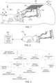
- FIG. 1 illustrates an example of a mesh installation rig. Even though mesh installation rig 100 is illustrated as an underground mesh installation rig, example embodiments of the present disclosure may be applied also to other type of mesh installation machines, for example rigs configured for installing meshes on rock cuttings along roads or railways.
- Mesh installation rig 100 may be an automated mesh installation rig, for example an automated mining vehicle equipped with tools configured for mesh installation.
- An automated mining vehicle for example an automated mesh installation rig, operating in an automatic mode may be configured to, for example, receive a task to be performed, perceive the environment of the automated mining vehicle, and autonomously perform the task while taking the environment into account.
- An automated mining vehicle operating in an automatic mode may be configured to operate independently but may be taken under external control at certain operation areas or conditions, such as during states of emergencies.
- Example embodiments may be however applied also in non-autonomous or semi- autonomous mining vehicles, for example remote-controlled mining vehicles.
- axis x represents the forward driving direction of mesh installation rig 100.
- Axis z represents the vertical direction, in this example towards the roof of the tunnel.
- Mesh installation rig 100 may comprise a movable carrier 110 and at least one boom 120 connected to movable carrier 110.
- Movable carrier 110 may comprise equipment for moving or stabilising mesh installation rig 100, such as for example a motor, wheels, or stabilizer jacks.
- Movable carrier 110 may be configured to move autonomously or it may be controlled by a human operator, either remotely or locally at mesh installation rig 100.
- mesh installation rig 100 may generally comprise one or a plurality (e.g., two, three, four,...) of booms 120.
- Boom 120-1 may be referred to as a first boom.
- Boom 120-2 may be referred to as a second boom.
- a gripper 124 may be coupled to a distal end portion of boom 120-1.
- Gripper 124 may be configured to grab and hold mesh 601, for example to enable boom 120-1 to position mesh 601 at rock surface 140.
- Rock surface 140 may comprise the roof of the tunnel and/or at least some of the walls of the tunnel.
- a bolter 126 may be coupled to a distal end portion of boom 120-2.
- Bolter 126 may be configured to mount mesh 601 at rock surface 140. Bolting is provided as one example of mounting mesh 601 to rock surface 140, but other means for mounting, such as for example riveting, may be also used.
- Mesh installation rig 100 may comprise at least one sensor 112 for scanning environment of mesh installation rig 100, for example, rock surface 140 and any meshes already installed thereon.
- Sensor 112 may include for example one or more of the following: a camera, a radio detection and ranging (radar) sensor, or a light detection and ranging (lidar) sensor. Sensor 112 may therefore comprise a group of two or more sensors.
- Sensor 112 may be configured to scan rock surface 140 to detect meshes, for example particular features thereof, such as edge(s) or corner(s) of the meshes.
- Scanning rock surface 140 may comprise scanning with sensor 112 such that its sensing direction is towards rock surface 140.
- Scanning rock surface 140 does not necessarily include detecting features of rock surface 140.
- scanning rock surface 140 may comprise pointing sensor 112 towards rock surface 140 and detecting meshes installed on rock surface 140.
- a radar sensor may be configured to transmit electromagnetic energy towards rock face and to observe the echoes returned from the mesh to determine distances to different points of the mesh.
- mesh installation rig 100 may obtain point cloud data that represents the scanned environment.
- the point cloud data may for example comprise three-dimensional (3D) model of a detected mesh, or at least certain features such as edge(s) of the mesh.
- a position of the mesh, or certain points such as corners or edges of the mesh may be determined based on the scanning data.
- the position of the mesh may be therefore fixed to, or known in relation to, a coordinate system or frame of mesh installation rig 100 (e.g., coordinate frame F rig ).
- the coordinate frame of mesh installation rig 100 may be stationary with respect to mesh installation rig 100.
- Mesh controller 114 may be configured to map the position(s) of the detected meshes to a coordinate system that is stationary with respect to rock surface 140 (e.g., coordinate frame F tunnel ), for example for providing feedback on actual positions of installed meshes on rock surface 140.
- a coordinate system that is stationary with respect to rock surface 140 (e.g., coordinate frame F tunnel ), for example for providing feedback on actual positions of installed meshes on rock surface 140.
- Mesh installation rig 100 may comprise a mesh controller (MC) 114.
- Mesh controller 114 may be for example provided as a software application residing on a memory and being executable by a processor.
- An example of an apparatus suitable for implementing mesh controller 114 is provided in FIG. 9 .
- Mesh controller 114 may comprise, or be communicatively coupled to, various functions, blocks, or applications for implementing functionality of mesh controller 114.
- mesh controller 114 may comprise or be communicatively coupled to a data management server, which may be configured to store information on a digital meshing plan, tunnel lines, point cloud or mesh presentations of tunnel lines or profiles, a mine map point cloud, or the like.
- the digital meshing plan may comprise planned mesh positions and optionally also planned mounting positions.
- a mesh position may comprise a position of a mesh on rock surface 140.
- a mounting position may comprise a position of mounting means (e.g., a bolt or a rivet) by which the mesh is mounted to rock surface 140.
- a planned mounting position may comprise a planned position for the mounting means at rock surface 140.
- Mesh controller 114 may be configured to control installation of mesh 601 based on a planned position of mesh 601 and/or planned mounting position(s) of mesh 601. The planned position of mesh 601 and/or its mounting position(s) may be provided with respect to a coordinate system of mesh installation rig 100, for example coordinate frame F rig that is stationary with respect to mesh installation rig 100 (e.g., movable carrier 110).
- Mesh controller 114 may comprise a navigation application configured to control, or enable a human operator to control, navigation of mesh installation rig 100, for example to move mesh installation rig 100 to a desired position (installation position) for installing a mesh at its planned position on rock surface 140 and/or to determine planned mesh position(s) or planned mounting position(s) of the digital meshing plan relative to a current position of mesh installation rig 100.
- a position of mesh installation rig 100 may be referred to as a navigation position.
- An installation position may be therefore a navigation position, which has been planned or determined for mesh installation rig 100 to install a mesh at rock surface 140.
- Mesh controller 114 may be configured to determine and/or maintain the digital meshing plan, a 3D model of at least one component of mesh installation rig 100 (e.g., a 3D model of boom(s) 120, gripper 124 or bolter 126), and/or a kinematic model of mesh installation rig 100, or component(s) thereof.
- a 3D model of a component of mesh installation rig 100 may comprise 3D geometry data of the component, obtained for example from a computer aided design (CAD) model of the respective physical component.
- the digital meshing plan may be provided as part of a drilling plan.
- the drilling plan may comprise planned drilling positions at rock surface 140, for example for bolting rock surface 140 (without meshing) to strengthen rock surface 140.
- a kinematic model of mesh installation rig 100, or component(s) thereof, may comprise a mathematical description of at least a part of mesh installation rig 100.
- a kinematic model may describe motion of mesh installation rig 100 or component(s) of mesh installation rig 100 without taking into account the forces that cause the motion.
- the kinematic model may be used for estimating or simulation of a position of mesh installation rig 100 or component(s) of mesh installation rig 100, for example based on measurement data from one or more sensors associated with mesh installation rig 100 or motion of mesh installation rig 100 caused, or to be caused, by given control inputs.
- the kinematic model of mesh installation rig 100 may comprise at least dimensions of mesh installation rig 100 and/or reach of mesh installation rig 100 such as a movement range of at least one boom 120 of mesh installation rig 100.
- the kinematic model may comprise information on dimensions of boom(s) 120, or parts thereof, for example gripper 124 or bolter 126, characteristics of joint(s) 122 (e.g., their degrees of freedom), constraints between moving parts of mesh installation rig 100, or the like.
- the kinematic model may thus enable modelling movement of the component(s) of mesh installation rig 100, for example to determine possible positions for installing mesh 601 from a particular installation position or to predict/prevent collisions between component(s) of mesh installation rig, mesh 601, and/or rock surface 140.
- the kinematic model may for example enable determining a maximum distance reachable by gripper 124 or bolter 126.
- the 3D model(s) of the component(s) may be provided as point cloud data indicative of the surface of the component(s).
- Point cloud data may comprise a plurality of data points representing, for example, distances between mesh installation rig 100 and its component(s) or other objects in the environment of mesh installation rig 100, for example at a particular time instance.
- An individual point included in a point cloud may be presented by, for example, x and y coordinates, or x, y, and z coordinates with respect to a particular coordinate frame (e.g., F rig ).
- Mesh installation rig 100 may be controlled by a remote mesh control device 200, which may be external to mesh installation rig 100, as illustrated in FIG. 2 .
- Remote mesh control device 200 may be for example a server located remote from mesh installation rig 100, for example outside the tunnel.
- Functionality of mesh controller 114 may be provided at mesh installation rig 100, remote mesh control device 200, or distributed between mesh installation rig 100 and remote mesh control device 200.
- Information may be exchanged between remote mesh control device 200 and mesh installation rig 100 over a communication interface including any suitable wireless or wired connection. Examples of suitable communication interfaces are described with reference to FIG. 9 .
- Mesh controller 114 may be configured to determine and/or maintain the digital meshing plan.
- the 3D and kinematic model(s) of mesh installation rig 100 may be stored at mesh controller 114, for example based on pre-configuration of the models at mesh controller 114.
- mesh controller 114 may be configured to receive one or more of the models from mesh installation rig 100 or the data management server. Example embodiments of the present disclosure may be thus implemented locally at mesh installation rig 100 and/or at remote mesh control device 200.
- FIG. 3 illustrates an example of a data structure of a digital meshing plan.
- the data structure of a digital meshing plan may comprise a computer-implemented data structure embodied on a computer-readable medium for controlling mesh installation.
- the data structure may be provided on a memory, such as for example a computer-readable storage medium, examples of which include, but are not limited to, movable storage devices (e.g., universal serial bus stick, compact disc, or the like). Further examples of suitable types of memory for storing the digital meshing plan are described with reference to the at least one memory 904 of FIG. 9 .
- Cardinality between data structures or attributes is represented by values "0", "1" or "*".
- data structure digital _ meshing _ plan may be associated with one or a plurality of ("1... *") data structures mesh, which may comprise or be associated with one attribute planned _ mesh _ position.
- Data structure mesh may comprise or be associated with zero or more (“0... *”) attributes planned_mounting_position and/or zero to one (“0...1”) attributes mesh strand thickness or mesh _ weight.
- a data structure digital meshing _ plan may comprise the digital meshing plan
- Data structure digital meshing _ plan may be associated with one or more other data structures, such as for example data structure mesh comprising information associated with one mesh.
- a data structure may be also called an object, a data object, or an information object.
- Data structure digital meshing _ plan may comprise or be associated with one or more attributes (e.g., parameters) that may be common to the data structure.
- digital meshing _ plan may comprise or be associated with attribute planned_mesh_overlap configured to indicate a planned overlapping of meshes of the digital meshing plan (e.g., different instances of data structure mesh ) .
- the planned overlapping may be indicated for example in terms of a number of overlapping mesh openings (mesh eyes).
- the planned overlapping may be for example at least two (e.g., 2-4) mesh openings. Overlap of 2-4 mesh openings may sufficiently prevent rocks from falling from rock surface 140, while not causing excessive extra cost due to increased number of meshes.
- the amount of overlapping may be defined for example with respect to a direction perpendicular to an edge of a previously installed mesh.
- Data structure digital_meshing _ plan may comprise or be associated with attribute minimum_height configured to indicate a height (minimum meshing height), measured for example from a floor of a tunnel, above which rock surface 140 is planned to be covered by the meshes of the digital meshing plan.
- a value of planned_mesh_overlap or minimum _ height may be applicable for multiple (e.g., some or all) meshes of the digital meshing plan.
- Data structure digital_meshing _ plan may comprise or be associated with one or more (sub)data structures mesh.
- Data structure mesh may comprise or be associated with one or more attributes that are related to one mesh.
- data structure mesh may comprise or be associated with attribute planned _ mesh _ position, which may be configured to indicate a planned position of a mesh on rock surface 140 for installation of the mesh to rock surface 140 by mesh installation rig 100.
- the planned position of the mesh may be configured to be indicated with respect to a coordinate frame that is stationary with respect to rock surface 140, e.g., with respect to the coordinate frame of the tunnel ( F tunnel ).
- the planned position of the mesh may comprise a planned position of least one part
- planned positions of two corners of the mesh may be provided to indicate the planned position of the mesh.
- a planned position of a single point (e.g., a corner) of the mesh may be provided along with a planned orientation of the mesh, in order to indicate the planned position of the mesh.
- An instance of data structure mesh may comprise or be associated with one attribute planned _ mesh _ position.
- the attribute planned _ mesh _ position may however comprise one or more positions corresponding to different parts of the mesh.
- Data structure mesh may comprise or be associated with zero or more ("0... *") attributes planned _ mounting _ position, which may be configured to indicate planned mounting position(s) for installation of the associated mesh to rock surface 140.
- the planned mounting position(s) may be configured to be indicated with respect to a coordinate frame (e.g., F tunnel ) that is stationary with respect to rock surface 140, for example the same coordinate frame used for indicating the planned position of the mesh.
- the planned position of the mesh or the planned mounting position(s) may be provided as a three-dimensional (3D) position(s), which may directly indicate the relevant position at the coordinate frame stationary with respect to rock surface 140.
- the planned position(s) may be indicated as a two-dimensional (2D) position, for example on a 2D projection of rock surface 140 or as 2D position on a reference plane from which the position is projected to rock surface 140, as will be further described with reference to FIG. 6 or FIG. 7 .
- Data structure mesh may comprise or be associated with attribute mesh strand thickness, which may be configured to indicate a thickness of mesh strands of the associated mesh.
- Data structure mesh may comprise or be associated with attribute mesh_weight, which may be configured to indicate the weight of the associated mesh. Attributes mesh strand thickness and/or mesh _ weight may be alternatively comprised in or associated with data structure digital _ meshing _ plan, as illustrated in FIG. 4 . In this case, attributes mesh strand thickness and/or mesh_weight may be applicable to multiple (e.g., all) meshes of the digital meshing plan. Possible uses for various attributes of the digital meshing plan are further described with reference to FIG. 5 to FIG. 8 .
- Data structure digital meshing plan may further comprise other attributes, such as for example mesh size. Mesh size may be indicated for example with dimensions of the mesh or a size identifier (e.g., Size 1, Size 2, Size 3, etc.).
- An instance of data structure mesh may be identified by a mesh identifier, represented in this example by attribute mesh_id.
- One mesh may be associated with one mesh identifier (1... 1).
- a mesh identifier may comprise for example one or more of the following: a serial number, a type identifier (e.g., type number), or a part number of the mesh.
- a mesh identifier may therefore identify an individual mesh and/or a type of mesh.
- the mesh identifier may be associated with a planned position of rock surface 140 (e.g., by means of attribute planned _ mesh _ position ) .
- a type identifier may be configured to indicate for example one or more of the following: the shape of mesh eyes (e.g., square or diamond), size of the mesh eyes, a mesh with equal size of mesh eyes, a mesh with different mesh eye size with a particular pattern, material of the mesh (e.g., hot galvanized mesh, stainless mesh, ferritic mesh), size of mesh (e.g., 2270 mm x 2530 mm), or the like.
- the shape of mesh eyes e.g., square or diamond
- size of the mesh eyes e.g., a mesh with equal size of mesh eyes, a mesh with different mesh eye size with a particular pattern
- material of the mesh e.g., hot galvanized mesh, stainless mesh, ferritic mesh
- size of mesh e.g., 2270 mm x 2530 mm
- Data structure digital_meshing _ plan may comprise or be associated with zero or more (0... *) data structures slot, which may represent a slot for installing a mesh at rock surface 140.
- a slot may be identified by a slot identifier (e.g., by attribute slot _ id ) .
- Data structure slot may comprise or be associated with zero or more (0... *) requirements (e.g., by attribute requirements ) , such as for example one or more required mesh properties for a mesh to be installed on the slot (e.g., attributes mesh_strand_thickness, mesh_weight or other properties such as for example material of the mesh, required mounting means, size of the mesh, or type of the mesh).
- Data structure slot may comprise or be associated with other properties, such as for example a position of the slot on rock surface 140, or position(s) of mesh to be installed on the slot.
- attributes planned_mesh _ position and/or planned _ mounting _ position may be associated with a slot (e.g., data structure slot having a particular slot _ id ) .
- This may be in addition or alternative to similar attribute(s) being associated with a particular mesh (e.g., data structure mesh having a particular mesh_id ) . Therefore, the planned position or mounting position(s) of a mesh may be indicated by attribute(s) of a slot.
- Mesh controller 114 may be configured to map a particular mesh to a particular slot.
- Mesh controller 114 may therefore be configured to create an association between a slot and a mesh, as illustrated by the dashed line.
- Mesh controller 114 may be configured to select a particular mesh or a mesh having a particular type or other required properties for instalment on a particular slot. The selection may be based on the requested mesh properties associated with the corresponding slot.
- Mesh controller 114 may be configured to select an individual mesh or a particular type of mesh based on finding a mesh having properties that fulfil the requirements of the slot.
- Data structure mesh may comprise or be associated with attributes actual_mesh _ position and/or actual _ mounting _ position. This may be the case for example if data structure slot comprises or is associated with attributes planned_mesh _ position and/or planned _ mounting _ position.
- Mesh controller 114 may be configured to assign values for actual_mesh _ position and/or actual _ mounting _ position based on the actual position of the mesh and/or its actual mounting positions, for example subsequent to installation of the mesh on rock surface 140. Even though particular hierarchy of data structures and attributes is illustrated in FIG. 3 and FIG. 4 , it is appreciated that similar functionality and benefits may be provided with other type of structures of the digital meshing plan.
- Attributes of a particular data structure may include attributes relating to characteristics of the object (e.g., digital or real object) represented by that data structure.
- attributes of a digital meshing plan e.g., data structure digital _ meshing _ plan
- attributes of a mesh may include attributes relating to characteristics of the mesh.
- Attributes of a slot may include attributes relating to characteristics of the slot.
- Such attributes may be referred to as (digital) meshing plan attributes, mesh attributes, or slot attributes, respectively.
- FIG. 5 illustrates an example of a flow chart for controlling mesh installation. Even though operations of the flow chart are described to be performed by mesh controller 114, they may be generally configured to be performed by an apparatus, such as for example mesh installation rig 100, a control apparatus thereof, or remote mesh control device 200.
- mesh controller 114 may obtain a meshing plan, for example as an instance of data structure digital _ meshing _ plan.
- the meshing plan may be digital, for example represented as binary digits (bits) or other digital values on a computer-readable memory.
- the meshing plan may be indicative of planned position(s) of mesh(es) on rock surface 140.
- the position(s) may be configured for installation of mesh(es) to rock surface 140 by mesh installation rig 100.
- the planned position(s) of the mesh(es) may be configured to be indicated with respect to coordinate frame F tunnel , or in general a coordinate frame that is stationary with respect to rock surface 140.
- Mesh controller 114 may be configured to obtain information on the mounting position(s) of the mesh(es), for example as part of the meshing plan.
- Mesh controller 114 may be configured to obtain the meshing plan by receiving the meshing plan, for example over an internal communication interface of mesh installation rig 100 or from a device external to mesh installation rig 100 (e.g., remote mesh control device 200). Alternatively, mesh controller 114 may be configured to obtain the meshing plan by retrieving it from at least one memory of an apparatus (e.g., a control apparatus) comprising mesh controller 114, or from at least one memory of mesh installation rig 100. This enables remote and/or local configuration of the digital meshing plan, thereby providing a flexible solution for controlling mesh installation.
- an apparatus e.g., a control apparatus
- mesh controller 114 may be configured to map the planned position(s) indicated in the meshing plan to a coordinate system of mesh installation rig 100, for example coordinate frame F rig , or in general a coordinate frame that is stationary with respect to mesh installation rig 100.
- Mesh installation rig 100 may be configured to monitor its location with respect to a coordinate frame (e.g., F tunnel ) that is stationary with respect to the rock surface 140, for example during navigation in a tunnel.
- mesh controller 114 may determine the planned position(s) with respect to its own coordinate frame (e.g., F rig ). This mapping may be performed for the planned position(s) of the mesh(es) and/or their planned mounting position(s).
- FIG. 6 illustrates an example of meshes installed on a tunnel surface based on a digital meshing plan.
- FIG. 6 illustrates a cross-sectional view of a tunnel along the yz -plane (left) and also an example of a meshing plan (right) for the tunnel surface viewed from above roof 140-1 and from outside of right wall 140-3 of the tunnel.
- rock surface 140 comprises a tunnel surface, for example roof 140-1 and/or wall(s) 140-2, 140-3 of the tunnel.
- Mesh controller 114 may be configured to determine positions for the meshes based on the digital meshing plan, which may comprise planned positions of meshes. Planned positions for meshes 601 to 606 are illustrated on the right.
- the digital meshing plan may comprise planned mounting positions 611 represented by the black dots.
- mesh controller 114 may be configured to initially use the respective position included in the digital meshing plan. However, due to various imperfections, such as for example bending or inaccurate placement of previous meshes, the planned position might not provide sufficient overlap in practise. It is also possible that mesh controller 114 determines that without reduction of the planned overlapping of the meshes, it is not possible to cover the rock surface above the minimum meshing height ( h ) with the predetermined number of meshes. At least for one of these reasons, mesh controller 114 may be configured to adjust planned mesh position(s) and/or mounting position(s), as will be further described with reference to operation 503.
- the planned mesh position(s) or mounting position(s) may be indicated as 2D point(s) on (2D) reference plane 600.
- Reference plane 600 may comprise a 2D projection of at least part of rock surface 140. Points of rock surface 140 (e.g., wall(s) and/or roof of the tunnel) may be represented on reference plane 600. Projecting of rock surface 140 to a 2D plane may comprise mapping points of rock surface 140 to the 2D plane. Each point of reference plane 600 may therefore correspond to one point on rock surface 140.
- Reference plane 600 may be also referred to as a 2D projection plane of rock surface 140. Another example of a reference plane is described with reference to FIG. 7 .
- Mesh controller 114 may be configured to determine a 3D position of the planned mesh position(s) and/or mounting position(s) based on the indicated respective 2D positions on reference plane 600. For example, mesh controller 114 may be configured to determine the planned mesh position(s) and/or mounting position(s) with respect to a coordinate frame stationary with respect to rock surface 140 (e.g., F tunnel ) and map the determined position(s) to coordinate frame of the mesh installation rig 100 (e.g., F rig ).
- rock surface 140 e.g., F tunnel
- FIG. 7 illustrates an example of projecting a two-dimensional position to a rock surface.
- the digital meshing plan may be configured to indicate the mesh position(s) or mounting position(s) on reference plane 701.
- Reference plane 701 may comprise a plane in a (Cartesian) coordinate system that is stationary with respect to rock surface 140 (e.g., F tunnel ).
- Mesh controller 114 may be configured to project planned mesh position(s) and/or mounting position(s) indicated on reference plane 701 to rock surface 140 to obtain respective projected position(s).
- mesh controller 114 may be configured to project mounting position 702 indicated on reference plane 701 to projected mounting position 702'.
- Mesh controller 114 may be configured to control installation of mounting of the mesh(es) based on the projected position(s).
- Reference plane 701 may be for example parallel to the floor of the tunnel or perpendicular to a vector of gravity.
- Presenting positions on a 2D reference plane 600, 700 enables a low-complex representation of the planned mesh position(s) and/or mounting position(s) in the digital meshing plan and therefore reduces the amount of memory needed for storing the digital meshing plan and/or the amount of data transmission resources needed for delivering the digital meshing plan to mesh installation rig 100.
- mesh installation rig 100 may be configured to adjust the planned position(s) of the mesh(es) and/or their mounting position(s). Adjustment of the planned position(s) enables mesh controller 114 to ensure that mesh installation is performed according to one or more preconfigured criteria, which may be indicated in the meshing plan and which may comprise for example the planned overlapping of meshes (e.g., attribute planned_mesh_overlap ) and/or the minimum meshing height (e.g., attribute minimum_height ) .
- preconfigured criteria which may be indicated in the meshing plan and which may comprise for example the planned overlapping of meshes (e.g., attribute planned_mesh_overlap ) and/or the minimum meshing height (e.g., attribute minimum_height ) .
- mesh controller 114 may be configured to adjust (e.g., reduce) the planned overlapping of meshes based on the indicated minimum meshing height, for example to enable to rock surface 140 to be covered above the indicated minimum meshing height from the floor of the tunnel, for example with a predetermined number of meshes.
- Mesh controller may be for example configured to reduce the planned overlapping from three mesh openings to two mesh openings, in order to enable rock surface to be covered according to the minimum meshing height.
- the predetermined number of meshes may for example comprise a number of meshes planned for a region of rock surface 140 that is to be covered by a single row of meshes (e.g., meshes 601, 602, 603 or meshes 604, 605, 606) extending from the highest point of the roof of the tunnel to the indicated minimum meshing height, or another upper limit for the number of meshes, indicated for example in the meshing plan.
- a single row of meshes e.g., meshes 601, 602, 603 or meshes 604, 605, 606
- the digital meshing plan may be configured to indicate a thickness of mesh strands for the mesh(es), for example by attribute mesh strand thickness.
- the thickness of mesh strands may affect how the meshes bend or fold, when mounted on the possibly very uneven rock surface 140.
- Meshes with thinner mesh wires may relatively closely follow rock surface 140, while meshes with thicker mesh wires may follow rock surface 140 more loosely. Installing meshes having thin mesh wires may therefore result in covering a smaller region of rock surface 140 than planned in the digital meshing plan.
- Mesh controller 114 may be therefore configured to determine a waste factor based on the thickness of the mesh strands.
- the waste factor may for example comprise a value between 0 and 1, where the value indicates how large area, or how long distance along a particular axis, is likely to be covered with a mesh having mesh wires having a certain thickness, for example when compared to the mesh positions of the digital meshing plan.
- Mesh controller 114 may be for example pre-configured with a look-up table comprising experimental data for waste factors different thicknesses of mesh wires. Based on the thickness indicated in the digital meshing plan, mesh controller 114 may be configured to select a corresponding waste factor. Mesh controller 114 may be alternatively configured to determine the waste factor based on comparing actual positions of the meshes, resulting from adjustment of the mesh positions, to positions indicated in the digital meshing plan. Mesh controller 114 may be configured to reduce the planned overlapping (e.g., from three mesh openings to two mesh openings) of the meshes based on the waste factor, for example such that the minimum meshing height (h) may be reached.
- the planned overlapping e.g., from three mesh openings to two mesh openings
- the meshes may be installed starting from the roof, for example from the highest point of roof 140-1, and moving down along the tunnel surface such that meshes located on wall 104-2, for example mesh 603, are installed after meshes located on roof 140-1, for example mesh 601 and mesh 602.
- a first mesh e.g., mesh 602
- a second mesh e.g., mesh 603
- a wall 140-2, 140-3 of the tunnel may comprise a portion of the tunnel surface for which the inclination angle ⁇ from axis y is below a threshold, for example less than 45°.
- Roof 140-1 of the tunnel may comprise a portion of the tunnel surface for which the inclination angle ⁇ from axis y is above the threshold, for example greater than 45°.
- FIG. 8 illustrates an example of overlapping meshes.
- mesh controller 114 may control installation of mesh 601 based on the digital meshing plan such that meshes 604 and 601 overlap in direction x after installation of mesh 601.
- Mesh controller 114 may determine the amount of overlapping based on the digital meshing plan (e.g., attribute planned_mesh_overlap ) and optionally adjust the planned overlap.
- Meshes 604 and 601 may overlap at an edge of mesh 604.
- mesh controller 114 may control installation of mesh 602 based on the digital meshing plan such that meshes 601 and 602 overlap in direction y after installation of mesh 602.
- Meshes 601 and 602 may overlap at an edge of mesh 601.
- the overlap between the meshes is slightly more than one mesh opening (mesh eye), but the amount of overlapping may be also larger, for example more than two (e.g., 2-4) mesh openings, as described above.
- the amount of overlapping may be defined with respect to a direction perpendicular to the edge of another mesh, for example direction x for installing mesh 601 such that it overlaps with mesh 604 and direction y for installing mesh 602 such that it overlaps with mesh 601.
- mesh controller 114 may be configured to control mesh installation.
- mesh controller 114 may be configured to control installation of the mesh(es) to rock surface 140 based on the planned position of the mesh(es), for example as indicated in the digital meshing plan and mapped to the coordinate system of mesh installation rig 100 (cf. operation 502), and/or as adjusted by mesh controller 114 (cf. operation 503).
- Mesh controller 114 may be configured to control mounting of the mesh(es) to rock surface 140 based on the planned mounting position(s), for example as indicated in the digital meshing plan and mapped to the coordinate system of mesh installation rig 100 (cf. operation 502), and/or as adjusted by mesh controller 114 (cf. operation 503).
- Controlling mesh installation may comprise controlling mounting of mesh 601 to rock surface 140.
- Controlling the mounting of mesh 601 may comprise causing mesh installation rig 100 to mount mesh 601 at rock surface 140.
- Controlling mounting of mesh 601 may comprise determining an order of mounting positions or a mounting rate (e.g., in bolts/min).
- Controlling mounting of mesh 601 may comprise causing mesh installation rig 100 to mount mesh 601 to rock surface 140 according to the determined order of mounting positions or the mounting rate.
- Controlling mounting of mesh 601 may comprise controlling movement of at least one boom, for example boom 120-2 comprising bolter 126, to cause mounting of mesh 601 to rock surface 140.
- Controlling mesh installation may therefore comprise controlling movement of at least one boom, for example booms 120-1, 120-2 and their respective tools, to cause both placement of mesh 601 at rock surface 140 and mounting of mesh 601 at rock surface 140 at this position.
- Controlling mesh installation may comprise controlling collision avoidance, for example when moving mesh 601 with boom 120-1 and gripper 124 or when moving bolter 126 for mounting mesh 601.
- Mesh controller 114, or mesh installation rig 100 may be configured to perform collision avoidance to avoid collisions between component(s) of mesh installation rig 100 (e.g., boom 120-1, boom 120-2, gripper 124, bolter 126, or movable carrier 110), mesh 601, or rock surface 140. Collision avoidance may be based on the kinematic model of mesh installation rig 100.
- the digital meshing plan may be configured to indicate the thickness of mesh strands and/or weight of the mesh(es). These attributes affect the 3D space occupied by mesh 601, for example due to bending when handling the mesh 601 with gripper 124.
- Mesh controller 114 may be therefore configured to determine a 3D space reservation (e.g., a space defined by height, width, and depth) for mesh 601. This determination may be based on the thickness of the mesh strands and/or the weight of mesh 601.
- mesh controller 114 may be configured with a look-up table comprising experimental data for 3D space reservations for different types of meshes (e.g., their size, weight, strand thickness, or the like).
- Mesh controller 114 may be configured to determine a corresponding space reservation from the look-up table based on the attributes of digital meshing plan.
- Mesh controller 114 may be configured to control collision avoidance in association with movement of mesh 601 based on the determined 3D space reservation, for example in combination with the kinematic model of mesh installation rig 100. This enables to avoid collisions that might otherwise occur due to bending of mesh 601.
- Controlling collision avoidance may comprise performing collision avoidance by mesh controller 114 itself or providing the determined 3D space reservation to a separate controller, for example within mesh installation rig 100.
- Performing collision avoidance based on the 3D space reservation, and optionally the kinematic model of mesh installation rig may comprise determining, for example by simulation, whether component(s) of mesh installation rig 100 or rock surface 140 would intersect with the 3D space reservation of mesh 601 when installing mesh 601 on rock surface 140.
- Mesh controller 114 or another controller, may be configured to control mesh installation such that the expected collision is avoided.
- mesh controller 114 may be configured to transmit feedback, for example indication(s) of actual position(s) of mesh(es) installed on rock surface 140 and/or their mounting position(s).
- Mesh controller 114 may be for example configured to determine the actual position of mesh 601 on rock surface 114 after installation of mesh 601.
- Mesh controller may be configured to determine the actual position of mesh 601 based on the actual mounting position(s) used for mounting mesh 601.
- Mesh controller 114 may determine the actual position or actual mounting position(s) of mesh 601 based on the adjusted position(s) determined at operation 503 or based on monitoring location and/or orientation of gripper 124 and/or a mounting tool (e.g., bolter 126) when installing mesh 601 on rock surface 140.
- a mounting tool e.g., bolter 1266
- mesh controller 114 may be configured to control scanning of rock surface 114 by sensor 112, in order to detect mesh 601.
- Mesh controller 114 may be configured to determine the actual position of mesh 601 based on scanning data of sensor 112.
- Mesh controller 114 may be configured to store actual position and/or actual mounting position(s) of mesh 601, for example in the digital meshing plan (e.g., as attributes actual_mesh _ position and/or actual _ mounting _ position, as described above).
- Mesh controller 114 may be configured to transmit an indication of the actual position of mesh(es) installed rock surface 140, for example over an internal communication interface of mesh installation rig 100 or to a device external to the mesh installation rig (e.g., remote mesh control device 200).
- Mesh controller 114 may transmit as feedback indication(s) of other parameter(s) associated with installing the meshes included in the digital meshing plan, for example indication(s) of actual mounting position(s) or the determined waste factor.
- the digital meshing plan may be then updated based on the feedback, for example by remote mesh control device 200, or another device internal or external to mesh installation rig 100 that receives the feedback.
- Mesh controller 114 may be configured to receive the updated digital meshing plan and to control installation or mounting of the mesh(es) based on the updated position(s) of the mesh(es) and/or their mounting position(s).
- Mesh controller 114 may be configured to transmit feedback on other parameters as well, such as for example actual mesh identifier(s) and/or actual type(s) of installed mesh(es) (e.g., associated with particular slots), or in general any parameters of the installed mesh(es).
- mesh controller 114 may be configured to determine an actual type of mounting means (e.g., bolt size).
- the actual identifier or type of a mesh or the type of mounting means may differ from corresponding parameters indicated in the digital meshing plan for example due to shortage of available meshes or mounting means during mesh installation.
- Mesh controller 114 may be configured to transmit this information as feedback, for example internally within mesh installation rig 100 or to an external device.
- the feedback may comprise other information associated with the installed meshes, such as for example an indication of size(s) of the installed mesh(es).
- the feedback may be provided for example with a data structure similar to digital _ meshing_plan, but including corresponding attributes(s) of the installed mesh(es), for example one or more of the following: an indication of actual position(s) of mesh(es) installed on rock surface 140, an indication of actual mounting position(s) of mesh(es) installed on rock surface 140, an indication of actual overlapping of the mesh(es), an indication of actual size(s) of the mesh(es), resulting for example from mesh controller 114 determining to switch the mesh size, for example in order to comply with requirement(s) (e.g., minimum meshing height) of the digital meshing plan.
- requirement(s) e.g., minimum meshing height
- mesh controller 114 and remote mesh control device 200 may be for example configured to synchronize their respective instances of the digital meshing plan such that mesh controller 114 receives updates to the meshing plan for installation of further meshes and remote mesh control device 200 receives information on previously installed meshes. This synchronization may be performed based on a predetermined schedule, for example periodically.
- FIG. 5 Some operations of FIG. 5 may be optional. For example, adjustment of the planned positions (cf. operation 503) and transmission of the feedback (cf. operation 505) might not be performed in some example embodiments. Where appropriate, operations may be also performed in different order.
- FIG. 9 illustrates an example of an apparatus configured to practise one or more example embodiments.
- Apparatus 900 may be or comprise a mesh control apparatus, such as for example a server, communicatively coupled to mesh installation rig 100, a mesh control apparatus located at mesh installation rig 100, mesh controller 114, mesh installation rig 100 itself, or in general any device or system configured to implement the functionality described herein.
- apparatus 900 is illustrated as a single device, it is appreciated that, wherever applicable, functions of apparatus 900 may be distributed to a plurality of devices.
- Apparatus 900 may comprise at least one processor 902.
- the at least one processor 902 may comprise, for example, one or more of various processing devices, such as for example a co-processor, a microprocessor, a controller, a digital signal processor (DSP), a processing circuitry with or without an accompanying DSP, or various other processing devices including integrated circuits such as, for example, an application specific integrated circuit (ASIC), a field programmable gate array (FPGA), a microcontroller unit (MCU), a hardware accelerator, a special-purpose computer chip, or the like.
- various processing devices such as for example, an application specific integrated circuit (ASIC), a field programmable gate array (FPGA), a microcontroller unit (MCU), a hardware accelerator, a special-purpose computer chip, or the like.
- ASIC application specific integrated circuit
- FPGA field programmable gate array
- MCU microcontroller unit
- hardware accelerator a special-purpose computer chip, or the like.
- Apparatus 900 may further comprise at least one memory 904.
- the at least one memory 904 may be configured to store, for example, computer program code or the like, for example operating system software and application software.
- the at least one memory 904 may comprise one or more volatile memory devices, one or more non-volatile memory devices, and/or a combination thereof.
- the memory may be embodied as magnetic storage devices (such as hard disk drives, etc.), optical magnetic storage devices, or semiconductor memories (such as mask ROM, PROM (programmable ROM), EPROM (erasable PROM), flash ROM, RAM (random access memory), etc.).
- Memory 904 is provided as an example of a (non-transitory) computer readable medium.
- non-transitory is a limitation of the medium itself (i.e., tangible, not a signal ) as opposed to a limitation on data storage persistency (e.g., RAM vs. ROM).
- the at least one memory 904 may be also embodied separate from apparatus 900, for example as a computer readable (storage) medium, examples of which include memory sticks, compact discs (CD), or the like.
- apparatus 900 When apparatus 900 is configured to implement some functionality, some component and/or components of apparatus 900, such as for example the at least one processor 902 and/or the at least one memory 904, may be configured to implement this functionality. Furthermore, when the at least one processor 902 is configured to implement some functionality, this functionality may be implemented using program code 906 comprised, for example, in the at least one memory 904.
- apparatus 900 comprises a processor or processor circuitry, such as for example a microcontroller, configured by the program code 906, when executed, to execute the embodiments of the operations and functionality described herein.
- Program code 906 is provided as an example of instructions which, when executed by the at least one processor 902, cause performance of apparatus 900.
- mesh controller 114 may be at least partially implemented as program code configured to cause apparatus 900 to perform functionality of mesh controller 114.
- transmission or reception of data e.g. sensor data, kinematic model(s), or the digital meshing plan
- data e.g. sensor data, kinematic model(s), or the digital meshing plan
- the functionality described herein can be performed, at least in part, by one or more hardware logic components.
- illustrative types of hardware logic components include field-programmable gate arrays (FPGAs), application-specific integrated circuits (ASICs), application-specific standard products (ASSPs), system-on-a-chip systems (SOCs), complex programmable logic devices (CPLDs), graphics processing units (GPUs), neural processing unit (NPU), tensor processing unit (TPU), or the like.
- Apparatus 900 may comprise a communication interface 908 configured to enable apparatus 900 to transmit and/or receive information.
- Communication interface 908 may comprise an internal or external communication interface, such as for example a radio interface between mesh installation rig 100 and remote mesh control device 200.
- Apparatus 900 may further comprise other components and/or functions such as for example a user interface (not shown) comprising at least one input device and/or at least one output device.
- the input device may take various forms such as a keyboard, a touch screen, or one or more embedded control buttons.
- the output device may for example comprise a display, a speaker, or the like.
- the user interface may enable a human operator to monitor various functions and data, such as for example the digital meshing plan, or the like.
- Apparatus 900 may be configured to perform or cause performance of any aspect of the method(s) described herein.
- a computer program or a computer program product may comprise instructions for causing, when executed by apparatus 900, apparatus 900 to perform any aspect of the method(s) described herein.
- apparatus 900 may comprise means for performing any aspect of the method(s) described herein.
- the means comprises the at least one processor 902, the at least one memory 904 including program code 906 (instructions) configured to, when executed by the at least one processor 902, cause apparatus 900 to perform the method(s).
- computer program instructions may be executed on means providing generic processing functions. Such means may be embedded for example in a computer, a server, or the like.
- the method(s) may be thus computer-implemented, for example based algorithm(s) executable by the generic processing functions, an example of which is the at least one processor 902.
- Apparatus 900 may comprise means for transmitting or receiving information, for example one or more wired of wireless (e.g. radio) transmitters or receivers, which may be coupled or be configured to be coupled to one or more antennas, or transmitter(s) or receiver(s) of a wired communication interface.
- FIG. 10 illustrates an example of a method for controlling mesh installation.
- an apparatus for controlling mesh installation may comprise: at least one processor; and at least one memory including computer program code, the at least one memory and the computer program code configured to, with the at least one processor, cause the apparatus at least to: obtain a meshing plan indicative of a planned position of at least one mesh on a rock surface for installation of the at least one mesh to the rock surface by a mesh installation rig, wherein the planned position of the at least one mesh is configured to be indicated with respect to a coordinate frame that is stationary with respect to the rock surface; map the planned position of the at least one mesh to a coordinate frame of the mesh installation rig; and control installation of the at least one mesh to the rock surface based on the planned position of at least one mesh.
- the planned position of the at least one mesh comprises a planned position of at least one part of the at least one mesh on the rock surface.
- the meshing plan is configured to indicate at least one planned mounting position for the installation of the at least one mesh to the rock surface, wherein the at least one planned mounting position is configured to be indicated with respect to the coordinate frame that is stationary with respect to the rock surface.
- the computer program code is further configured to, with the at least one processor, cause the apparatus to: map the at least one planned mounting position to the coordinate frame of the mesh installation rig; and control mounting of the at least one mesh to the rock surface based on the at least one planned mounting position.
- the meshing plan is configured to indicate the planned position of the at least one mesh and/or the planned mounting position as a two-dimensional position on a reference plane.
- the reference plane comprises a two-dimensional projection of at least part of the rock surface.
- the reference plane is parallel to a floor of a tunnel or perpendicular to a vector of gravity.
- the computer program code is further configured to, with the at least one processor, cause the apparatus to: project the at least one planned position of the at least one mesh or the planned mounting position from the reference plane to the rock surface to obtain at least one projected position; and control installation or mounting of the at least one mesh to the rock surface based on the at least one projected position.
- the meshing plan is configured to indicate a planned overlapping of the at least one mesh and at least one other mesh.
- the computer program code is further configured to, with the at least one processor, cause the apparatus to: adjust the planned position of the at least one mesh to cause installation of the at least one mesh substantially with the planned overlapping with the at least one other mesh.
- the meshing plan is configured to indicate a thickness of mesh strands and/or a weight of the at least one mesh.
- the computer program code is further configured to, with the at least one processor, cause the apparatus to: determine, based on the thickness of the mesh strands and/or the weight of the at least one mesh, a three-dimensional space reservation for the at least one mesh; and control, based on the three-dimensional space reservation, collision avoidance in association with movement of the at least one mesh by the mesh installation rig.
- the meshing plan is configured to indicate a height from a floor of a tunnel, wherein the rock surface is planned to be covered by the at least one mesh above the height from the floor of the tunnel.
- the computer program code is further configured to, with the at least one processor, cause the apparatus to: reduce the planned overlapping of the at least one mesh and the at least one other mesh based on the indicated height from the floor of the tunnel, to enable the rock surface to be covered above the indicated height from the floor of the tunnel with a predetermined number of meshes.
- the computer program code is further configured to, with the at least one processor, cause the apparatus to: determine, based on the thickness of the mesh strands of the at least one mesh, a waste factor for installing the at least one mesh and the at least one other mesh on the rock surface; and reduce the planned overlapping of the at least one mesh and the at least one other mesh based on the waste factor.
- the computer program code is further configured to, with the at least one processor, cause the apparatus to: receive the meshing plan over an internal communication interface of the mesh installation rig or from a device external to the mesh installation rig, or retrieve the meshing plan from the at least one memory of the apparatus or at least one memory of the mesh installation rig.
- the computer program code is further configured to, with the at least one processor, cause the apparatus to: determine an actual position of the at least one mesh installed on the rock surface and/or an indication of at least one actual mounting position of the at least one mesh; and transmit an indication of the actual position of the at least one mesh installed on the rock surface and/or the indication of the at least one actual mounting position of the at least one mesh over an internal communication interface of the mesh installation rig or to a device external to the mesh installation rig.
- the meshing plan is configured to indicate an identifier or a type of the at least one mesh associated with the planned position.
- the computer program code is further configured to, with the at least one processor, cause the apparatus to: determine and transmit an actual identifier or an actual type of the at least one mesh installed on the rock surface and/or an actual type of mounting means used for mounting the at least one mesh to the rock surface over an internal communication interface of the mesh installation rig or to a device external to the mesh installation rig.
- the planned position of the at least one mesh is associated with a slot identifier of a slot on the rock surface, wherein the slot is associated with one or more requested mesh properties.
- the computer program code is further configured to, with the at least one processor, cause the apparatus to: select the at least one mesh for instalment on the planned position based on the one or more requested mesh properties of the slot.
- a mesh installation rig is disclosed.
- the mesh installation rig may comprise the apparatus according to any example embodiment of the first aspect
- FIG. 10 illustrates another example of a method for controlling mesh installation, according to a third aspect of the present disclosure.
- the method may comprise a computer-implemented method performed by, for example, apparatus 900 such as mesh controller 114.
- the method may comprise obtaining a meshing plan indicative of a planned position of at least one mesh on a rock surface for installation of the at least one mesh to the rock surface by a mesh installation rig, wherein the planned position of the at least one mesh is configured to be indicated with respect to a coordinate frame that is stationary with respect to the rock surface.
- the method may comprise mapping the planned position of the at least one mesh to a coordinate frame of the mesh installation rig
- the method may comprise controlling installation of the at least one mesh to the rock surface based on the planned position of at least one mesh.
- the method may be performed by mesh controller 114, mesh installation rig 100, or remote mesh control device 200, for example based on program code 906, when executed by processor 902.
- program code 906 when executed by processor 902.
- Various examples of the methods are explained above with regard to functionalities of mesh controller 114, mesh installation rig 100, and/or remote mesh control device 200. It should be understood that example embodiments described may be combined in different ways unless explicitly disallowed.
- the planned position of the at least one mesh comprises a planned position of at least one part of the at least one mesh on the rock surface.
- the meshing plan is configured to indicate at least one planned mounting position for the installation of the at least one mesh to the rock surface, wherein the at least one planned mounting position is configured to be indicated with respect to the coordinate frame that is stationary with respect to the rock surface.
- the method may comprise: mapping the at least one planned mounting position to the coordinate frame of the mesh installation rig; and control mounting of the at least one mesh to the rock surface based on the at least one planned mounting position.
- the meshing plan is configured to indicate the planned position of the at least one mesh and/or the planned mounting position as a two-dimensional position on a reference plane.
- the reference plane comprises a two-dimensional projection of at least part of the rock surface.
- the reference plane is parallel to a floor of a tunnel or perpendicular to a vector of gravity.
- the method may comprise: projecting the at least one planned position of the at least one mesh or the planned mounting position from the reference plane to the rock surface to obtain at least one projected position; and controlling installation or mounting of the at least one mesh to the rock surface based on the at least one projected position.
- the meshing plan is configured to indicate a planned overlapping of the at least one mesh and at least one other mesh.
- the method may comprise: adjusting the planned position of the at least one mesh to cause installation of the at least one mesh substantially with the planned overlapping with the at least one other mesh.
- the meshing plan is configured to indicate a thickness of mesh strands and/or a weight of the at least one mesh.
- the method may comprise: determining, based on the thickness of the mesh strands and/or the weight of the at least one mesh, a three-dimensional space reservation for the at least one mesh; and controlling, based on the three-dimensional space reservation, collision avoidance in association with movement of the at least one mesh by the mesh installation rig.
- the meshing plan is configured to indicate a height from a floor of a tunnel, wherein the rock surface is planned to be covered by the at least one mesh above the height from the floor of the tunnel.
- the method may comprise: reducing the planned overlapping of the at least one mesh and the at least one other mesh based on the indicated height from the floor of the tunnel, to enable the rock surface to be covered above the indicated height from the floor of the tunnel with a predetermined number of meshes.
- the method may comprise: determining, based on the thickness of the mesh strands of the at least one mesh, a waste factor for installing the at least one mesh and the at least one other mesh on the rock surface; and reducing the planned overlapping of the at least one mesh and the at least one other mesh based on the waste factor.
- the method may comprise: receiving the meshing plan over an internal communication interface of the mesh installation rig or from a device external to the mesh installation rig, or retrieve the meshing plan from the at least one memory of the apparatus or at least one memory of the mesh installation rig.
- the method may comprise: determining an actual position of the at least one mesh installed on the rock surface and/or an indication of at least one actual mounting position of the at least one mesh; and transmitting an indication of the actual position of the at least one mesh installed on the rock surface and/or the indication of the at least one actual mounting position of the at least one mesh over an internal communication interface of the mesh installation rig or to a device external to the mesh installation rig.
- the meshing plan is configured to indicate an identifier or a type of the at least one mesh associated with the planned position.
- the method comprises: determining and transmitting an actual identifier or an actual type of the at least one mesh installed on the rock surface and/or an actual type of mounting means used for mounting the at least one mesh to the rock surface over an internal communication interface of the mesh installation rig or to a device external to the mesh installation rig.
- the planned position of the at least one mesh is associated with a slot identifier of a slot on the rock surface, wherein the slot is associated with one or more requested mesh properties for the slot.
- the method comprises: selecting the at least one mesh for instalment on the planned position based on the one or more requested mesh properties of the slot.
- the method may be performed by the mesh installation rig.
- an apparatus may comprise means for performing the method according to the third aspect, or any example embodiment(s) thereof.
- a computer program, a computer program product, or a (non-transitory) computer-readable medium may comprise instructions which, when executed by an apparatus, cause the apparatus at least to perform the method according to the third aspect, or any example embodiment(s) thereof.
- a data structure may comprise: an indication of a planned position of at least one mesh on a rock surface for installation of the at least one mesh to the rock surface by a mesh installation rig, wherein the planned position of the at least one mesh is configured to be indicated with respect to a coordinate frame that is stationary with respect to the rock surface.
- the data structure may comprise at least one of the following: an indication of at least one planned mounting position for the installation of the at least one mesh to the rock surface, wherein the at least one planned mounting position is configured to be indicated with respect to the coordinate frame that is stationary with respect to the rock surface, an indication of a planned overlapping of the at least one mesh and at least one other mesh, an indication of a thickness of mesh strands and/or a weight of the at least one mesh, or an indication of a height from a floor of a tunnel, wherein the rock surface is planned to be covered by the at least one mesh above the height from the floor of the tunnel.
- the planned position of the at least one mesh comprises a planned position of at least one part of the at least one mesh on the rock surface.
- the meshing plan is configured to indicate the planned position of the at least one mesh and/or the planned mounting position as a two-dimensional position on a reference plane.
- the reference plane comprises a two-dimensional projection of at least part of the rock surface.
- the reference plane is parallel to a floor of a tunnel or perpendicular to a vector of gravity.
- the meshing plan is configured to indicate a planned overlapping of the at least one mesh and at least one other mesh.
- the meshing plan is configured to indicate a thickness of mesh strands and/or a weight of the at least one mesh.
- the meshing plan is configured to indicate a mesh identifier or a type of the at least one mesh associated with the planned position.
- the meshing plan is configured to indicate a slot identifier of a slot on the rock surface for instalment of the at least one mesh, wherein the slot is associated with the planned position of the at least one mesh and/or one or more requested mesh properties for the slot.
- subjects may be referred to as 'first' or 'second' subjects, this does not necessarily indicate any order or importance of the subjects. Instead, such attributes may be used solely for the purpose of making a difference between subjects.
Landscapes
- Engineering & Computer Science (AREA)
- Mining & Mineral Resources (AREA)
- Life Sciences & Earth Sciences (AREA)
- General Life Sciences & Earth Sciences (AREA)
- Geochemistry & Mineralogy (AREA)
- Geology (AREA)
- Architecture (AREA)
- Civil Engineering (AREA)
- Structural Engineering (AREA)
- Image Generation (AREA)
- Aerials With Secondary Devices (AREA)
- Devices Affording Protection Of Roads Or Walls For Sound Insulation (AREA)
- Management, Administration, Business Operations System, And Electronic Commerce (AREA)
- Lining And Supports For Tunnels (AREA)
- Roof Covering Using Slabs Or Stiff Sheets (AREA)
Priority Applications (8)
| Application Number | Priority Date | Filing Date | Title |
|---|---|---|---|
| EP23152076.8A EP4403745A1 (de) | 2023-01-17 | 2023-01-17 | Eingriffsplan zur steuerung der mesh-installation |
| PCT/EP2024/051034 WO2024153695A1 (en) | 2023-01-17 | 2024-01-17 | Meshing plan for controlling mesh installation |
| CN202480005695.4A CN120344751A (zh) | 2023-01-17 | 2024-01-17 | 用于控制网格安装的网格建立计划 |
| AU2024209847A AU2024209847A1 (en) | 2023-01-17 | 2024-01-17 | Meshing plan for controlling mesh installation |
| JP2025540759A JP2026503892A (ja) | 2023-01-17 | 2024-01-17 | メッシュ設置を制御するためのメッシング計画 |
| PE2025001128A PE20260016A1 (es) | 2023-01-17 | 2024-01-17 | Esquema de enmallado para controlar la instalacion de malla |
| CL2025002050A CL2025002050A1 (es) | 2023-01-17 | 2025-07-10 | Esquema de enmallado para controlar la instalación de malla. |
| MX2025008309A MX2025008309A (es) | 2023-01-17 | 2025-07-16 | Esquema de enmallado para controlar la instalacion de malla |
Applications Claiming Priority (1)
| Application Number | Priority Date | Filing Date | Title |
|---|---|---|---|
| EP23152076.8A EP4403745A1 (de) | 2023-01-17 | 2023-01-17 | Eingriffsplan zur steuerung der mesh-installation |
Publications (1)
| Publication Number | Publication Date |
|---|---|
| EP4403745A1 true EP4403745A1 (de) | 2024-07-24 |
Family
ID=84981868
Family Applications (1)
| Application Number | Title | Priority Date | Filing Date |
|---|---|---|---|
| EP23152076.8A Pending EP4403745A1 (de) | 2023-01-17 | 2023-01-17 | Eingriffsplan zur steuerung der mesh-installation |
Country Status (8)
| Country | Link |
|---|---|
| EP (1) | EP4403745A1 (de) |
| JP (1) | JP2026503892A (de) |
| CN (1) | CN120344751A (de) |
| AU (1) | AU2024209847A1 (de) |
| CL (1) | CL2025002050A1 (de) |
| MX (1) | MX2025008309A (de) |
| PE (1) | PE20260016A1 (de) |
| WO (1) | WO2024153695A1 (de) |
Citations (2)
| Publication number | Priority date | Publication date | Assignee | Title |
|---|---|---|---|---|
| CN109595014A (zh) * | 2018-11-06 | 2019-04-09 | 首钢集团有限公司 | 一种锚网支护方法 |
| CN112360525A (zh) * | 2020-11-09 | 2021-02-12 | 中国煤炭科工集团太原研究院有限公司 | 锚杆钻机铺网控制方法以及控制系统 |
-
2023
- 2023-01-17 EP EP23152076.8A patent/EP4403745A1/de active Pending
-
2024
- 2024-01-17 PE PE2025001128A patent/PE20260016A1/es unknown
- 2024-01-17 AU AU2024209847A patent/AU2024209847A1/en active Pending
- 2024-01-17 CN CN202480005695.4A patent/CN120344751A/zh active Pending
- 2024-01-17 JP JP2025540759A patent/JP2026503892A/ja active Pending
- 2024-01-17 WO PCT/EP2024/051034 patent/WO2024153695A1/en not_active Ceased
-
2025
- 2025-07-10 CL CL2025002050A patent/CL2025002050A1/es unknown
- 2025-07-16 MX MX2025008309A patent/MX2025008309A/es unknown
Patent Citations (2)
| Publication number | Priority date | Publication date | Assignee | Title |
|---|---|---|---|---|
| CN109595014A (zh) * | 2018-11-06 | 2019-04-09 | 首钢集团有限公司 | 一种锚网支护方法 |
| CN112360525A (zh) * | 2020-11-09 | 2021-02-12 | 中国煤炭科工集团太原研究院有限公司 | 锚杆钻机铺网控制方法以及控制系统 |
Also Published As
| Publication number | Publication date |
|---|---|
| WO2024153695A1 (en) | 2024-07-25 |
| CL2025002050A1 (es) | 2025-10-24 |
| MX2025008309A (es) | 2025-08-01 |
| AU2024209847A1 (en) | 2025-06-19 |
| JP2026503892A (ja) | 2026-02-02 |
| PE20260016A1 (es) | 2026-01-06 |
| CN120344751A (zh) | 2025-07-18 |
Similar Documents
| Publication | Publication Date | Title |
|---|---|---|
| EP3839203A1 (de) | Minenfahrzeugsicherheitssteuerung | |
| US12086921B2 (en) | Positioning of mobile device in underground worksite | |
| EP4403745A1 (de) | Eingriffsplan zur steuerung der mesh-installation | |
| US20260085583A1 (en) | Determination of an updated drilling plan | |
| EP4403743A1 (de) | Steuerung einer mesh-installation | |
| EP4403744A1 (de) | Steuerung einer mesh-installation | |
| EP4459098A1 (de) | Aktualisierung eines eingriffsplans auf basis eines tatsächlichen oberflächenmodells einer gesteinsoberfläche | |
| EP4459099A1 (de) | Steuerung einer mesh-installation auf basis eines mesh-verformungsparameters | |
| EP4534797A1 (de) | Positionsbestimmung für einen bolzen eines bolzenlüfters | |
| CN117058315A (zh) | 一种基于三维重建的无人矿车召唤系统 | |
| EP4407140A1 (de) | Steuerung des austauschs eines bergbauwerkzeugs eines bergbaufahrzeugs | |
| EP4575098A1 (de) | Bestimmung eines schaufelfüllparameterwerts für einen lader | |
| CA3147536C (en) | Positioning of mobile device in underground worksite | |
| EP4671488A1 (de) | Steuerung einer bohreinheit auf basis des abstands zur gesteinsoberfläche |
Legal Events
| Date | Code | Title | Description |
|---|---|---|---|
| PUAI | Public reference made under article 153(3) epc to a published international application that has entered the european phase |
Free format text: ORIGINAL CODE: 0009012 |
|
| STAA | Information on the status of an ep patent application or granted ep patent |
Free format text: STATUS: THE APPLICATION HAS BEEN PUBLISHED |
|
| AK | Designated contracting states |
Kind code of ref document: A1 Designated state(s): AL AT BE BG CH CY CZ DE DK EE ES FI FR GB GR HR HU IE IS IT LI LT LU LV MC ME MK MT NL NO PL PT RO RS SE SI SK SM TR |
|
| STAA | Information on the status of an ep patent application or granted ep patent |
Free format text: STATUS: REQUEST FOR EXAMINATION WAS MADE |
|
| 17P | Request for examination filed |
Effective date: 20250124 |