EP4403733A1 - Slide rail mechanism - Google Patents
Slide rail mechanism Download PDFInfo
- Publication number
- EP4403733A1 EP4403733A1 EP23184152.9A EP23184152A EP4403733A1 EP 4403733 A1 EP4403733 A1 EP 4403733A1 EP 23184152 A EP23184152 A EP 23184152A EP 4403733 A1 EP4403733 A1 EP 4403733A1
- Authority
- EP
- European Patent Office
- Prior art keywords
- rail
- slide rail
- drawer
- working member
- respect
- Prior art date
- Legal status (The legal status is an assumption and is not a legal conclusion. Google has not performed a legal analysis and makes no representation as to the accuracy of the status listed.)
- Pending
Links
Images






Classifications
-
- E—FIXED CONSTRUCTIONS
- E05—LOCKS; KEYS; WINDOW OR DOOR FITTINGS; SAFES
- E05B—LOCKS; ACCESSORIES THEREFOR; HANDCUFFS
- E05B65/00—Locks or fastenings for special use
- E05B65/46—Locks or fastenings for special use for drawers
- E05B65/462—Locks or fastenings for special use for drawers for two or more drawers
- E05B65/463—Drawer interlock or anti-tilt mechanisms, i.e. when one drawer is open, at least one of the remaining drawers is locked
- E05B65/464—Drawer interlock or anti-tilt mechanisms, i.e. when one drawer is open, at least one of the remaining drawers is locked comprising two or more lock elements aligned in end-to-end abutting relation
-
- A—HUMAN NECESSITIES
- A47—FURNITURE; DOMESTIC ARTICLES OR APPLIANCES; COFFEE MILLS; SPICE MILLS; SUCTION CLEANERS IN GENERAL
- A47B—TABLES; DESKS; OFFICE FURNITURE; CABINETS; DRAWERS; GENERAL DETAILS OF FURNITURE
- A47B88/00—Drawers for tables, cabinets or like furniture; Guides for drawers
- A47B88/40—Sliding drawers; Slides or guides therefor
- A47B88/49—Sliding drawers; Slides or guides therefor with double extensible guides or parts
-
- A—HUMAN NECESSITIES
- A47—FURNITURE; DOMESTIC ARTICLES OR APPLIANCES; COFFEE MILLS; SPICE MILLS; SUCTION CLEANERS IN GENERAL
- A47B—TABLES; DESKS; OFFICE FURNITURE; CABINETS; DRAWERS; GENERAL DETAILS OF FURNITURE
- A47B88/00—Drawers for tables, cabinets or like furniture; Guides for drawers
- A47B88/40—Sliding drawers; Slides or guides therefor
- A47B88/44—Sequencing or synchronisation of drawer slides or functional units
- A47B88/447—Simultaneous movement of rails within drawer slides, i.e. with a coordination of movement with all rail elements moving at the same time
-
- A—HUMAN NECESSITIES
- A47—FURNITURE; DOMESTIC ARTICLES OR APPLIANCES; COFFEE MILLS; SPICE MILLS; SUCTION CLEANERS IN GENERAL
- A47B—TABLES; DESKS; OFFICE FURNITURE; CABINETS; DRAWERS; GENERAL DETAILS OF FURNITURE
- A47B97/00—Furniture or accessories for furniture, not provided for in other groups of this subclass
-
- A—HUMAN NECESSITIES
- A47—FURNITURE; DOMESTIC ARTICLES OR APPLIANCES; COFFEE MILLS; SPICE MILLS; SUCTION CLEANERS IN GENERAL
- A47B—TABLES; DESKS; OFFICE FURNITURE; CABINETS; DRAWERS; GENERAL DETAILS OF FURNITURE
- A47B97/00—Furniture or accessories for furniture, not provided for in other groups of this subclass
- A47B2097/008—Anti-tip devices
-
- A—HUMAN NECESSITIES
- A47—FURNITURE; DOMESTIC ARTICLES OR APPLIANCES; COFFEE MILLS; SPICE MILLS; SUCTION CLEANERS IN GENERAL
- A47B—TABLES; DESKS; OFFICE FURNITURE; CABINETS; DRAWERS; GENERAL DETAILS OF FURNITURE
- A47B2210/00—General construction of drawers, guides and guide devices
- A47B2210/0002—Guide construction for drawers
- A47B2210/0064—Guide sequencing or synchronisation
- A47B2210/0067—Two slide synchronisation
Definitions
- the present invention relates to a slide rail system according to the pre-characterizing clauses of claim 1.
- U.S. Patent No. US 7,520,576B2 discloses an anti-tilt linkage mechanism that is applied for a vertical cabinet with several movable drawers.
- the vertical cabinet includes a file cabinet body, telescopic slide rails and two or more drawers.
- the telescopic slide rails are installed on the inner wall of the file cabinet body.
- the drawers are vertically installed inside the file cabinet body via the telescopic slide rails; when one drawer is pulled open, the other drawers cannot be pulled out from the file cabinet body.
- the linkage mechanism of the foresaid patent is only suitable for two or more slide rails (or the related drawers) that are installed in a vertical manner. Design of a linkage product of satisfying market competition and different operation demands is an important issue in the institutional design industry.
- the present invention aims at providing a slide rail system for solving above drawbacks.
- the slide rail mechanism includes a first slide rail assembly, a second slide rail assembly and a first working member.
- the first slide rail assembly and the second slide rail assembly are arranged on the cabinet.
- the first working member is shiftable with respect to the cabinet.
- the first slide rail assembly includes a first rail and a second rail.
- the second rail is shiftable with respect to the first rail in a longitudinal direction
- the second slide rail assembly includes a third rail and a fourth rail, and the fourth rail is shiftable with respect to the third rail in the longitudinal direction.
- the first working member is driven to shift in a first transverse direction, so as to prevent the fourth rail from being shifted with respect to the third rail of the second slide rail assembly in the actuation direction.
- furniture 20 can include a cabinet 22, and the cabinet 22 can include a plurality of drawers arranged in a transverse direction (such as lateral arrangement) and a plurality of drawers arranged in a vertical direction, such as a first drawer 24a, a second drawer 24b, a third drawer 24c and a fourth drawer 24d shown in FIG. 1 , and others are omitted herein for simplicity.
- the drawers can be pulled open and pushed into the cabinet 22.
- a slide rail mechanism can be arranged inside the cabinet 22.
- the slide rail mechanism can include a plurality of slide rail assemblies, such as a first slide rail assembly 26, a second slide rail assembly 28, a third slide rail assembly 30 and a fourth slide rail assembly 32 respectively configured to hold the first drawer 24a, the second drawer 24b, the third drawer 24c and the fourth drawer 24d.
- Each of the first slide rail assembly 26, the second slide rail assembly 28, the third slide rail assembly 30 and the fourth slide rail assembly 32 can include at least two slide rails being shiftable with respect to each other in a longitudinal direction.
- the longitudinal direction can be defined as X-axis direction (or can be interpreted as a lengthwise direction or a shifting direction of the slide rail);
- the transverse direction can be defined as Y-axis direction (or can be interpreted as a lateral direction of the slide rail);
- a vertical direction can be defined as Z-axis direction (or can be interpreted as a height direction of the slide rail).
- first slide rail assembly 26, the second slide rail assembly 28, the third slide rail assembly 30 and the fourth slide rail assembly 32 can be designed as a pair of slide rails respectively arranged on the left side and the right side of the corresponding drawer. Only parts of the foresaid pair of two slide rails, such as the first slide rail assembly 26, the second slide rail assembly 28, the third slide rail assembly 30 and the fourth slide rail assembly 32 can be shown in FIG. 2 and FIG. 3 .
- the cabinet 22 can include a plurality of stand walls, such as a first lateral wall 34, a second lateral wall 36, a first middle wall 38 and a second middle wall 40.
- the first middle wall 38 and the second middle wall 40 can be located between the first lateral wall 34 and the second lateral wall 36.
- the cabinet 22 can have some first spaces K1 located between the first lateral wall 34 and the first middle wall 38.
- the second drawer 24b can be accommodated inside one of the first spaces K1.
- the cabinet 22 can further have some second spaces K2 located between the first middle wall 38 and the second middle wall 40.
- the first drawer 24a and the fourth drawer 24d can be accommodated inside two of the second spaces K2.
- the cabinet 22 can further have some third space K3 located between the second middle wall 40 and the second lateral wall 36.
- the third drawer 24c can be accommodated inside one of the third spaces K3.
- the first slide rail assembly 26, the second slide rail assembly 28, the third slide rail assembly 30 and the fourth slide rail assembly 32 can be arranged inside the cabinet 22.
- the first slide rail assembly 26, the second slide rail assembly 28 and the third slide rail assembly 30 can be transversely arranged inside the cabinet 22.
- the fourth slide rail assembly 32 and the first slide rail assembly 26 can be vertically arranged inside the cabinet 22.
- the first slide rail assembly 26 can include a first rail 44 and a second rail 46.
- the second rail 46 can be shiftable with respect to the first rail 44 in the longitudinal direction.
- the second slide rail assembly 28 can include a third rail 48 and a fourth rail 50.
- the fourth rail 50 can be shiftable with respect to the third rail 48 in the longitudinal direction.
- the third slide rail assembly 30 can include a fifth rail 52 and a sixth rail 54.
- the sixth rail 54 can be shiftable with respect to the fifth rail 52 in the longitudinal direction.
- the fourth slide rail assembly 32 can include a seventh rail 56 and an eighth rail 58.
- the eighth rail 58 can be shiftable with respect to the seventh rail 56 in the longitudinal direction.
- the first rail 44 of the first slide rail assembly 26, the third rail 48 of the second slide rail assembly 28, the fifth rail 52 of the third slide rail assembly 30, and the seventh rail 56 of the fourth slide rail assembly 32 can be mounted on the cabinet 22, such as in a fixed manner.
- the second rail 46 of the first slide rail assembly 26, the fourth rail 50 of the second slide rail assembly 28, the sixth rail 54 of the third slide rail assembly 30, and the eighth rail 58 of the fourth slide rail assembly 32 can be respectively configured to hold the first drawer 24a, the second drawer 24b, the third drawer 24c and the fourth drawer 24d.
- each of the first slide rail assembly 26, the second slide rail assembly 28, the third slide rail assembly 30 and the fourth slide rail assembly 32 can further include a middle rail; that is to say, all the first slide rail assembly 26, the second slide rail assembly 28, the third slide rail assembly 30 and the fourth slide rail assembly 32 can be the three-rail slide rail assembly.
- the middle rail of the first slide rail assembly 26 can be movably mounted between the first rail 44 and the second rail 46.
- the slide rail mechanism can further include a first working member 60, and may preferably further include a second working member 62.
- each of the first working member 60 and the second working member 62 can be a rod, arrangement directions of the first working member 60 and the second working member 62 can be parallel to the transverse direction of the slide rail, and the first working member 60 and the second working member 62 can be shiftable with respect to the cabinet 22.
- the first working member 60 and the second working member 62 can be set in an initial mode; for example, the first working member 60 can be located on a first working position J1, and the second working member 62 can be located on a first preset position M1.
- first working member 60 and the second working member 62 can be shiftable with respect to the cabinet 22 in the transverse direction. Therefore, moving directions of the first working member 60 and the second working member 62 can be substantially the same as the transverse direction (or the lateral direction) of the slide rail.
- the first working member 60 and the second working member 62 can be mounted on the cabinet 22 via a casing (which is not shown in the figures), so as to increase motion stability of the first working member 60 and the second working member 62 with respect to the cabinet 22.
- each of the first working member 60 and the second working member 62 can include two end portions.
- the first working member 60 can include a first end portion 60a and a second end portion 60b opposite to each other
- the second working member 62 can include a first end portion 62a and a second end portion 62b opposite to each other.
- a first driving member 64 can be arranged on the first end portion 60a of the first working member 60 (which can be shown in FIG. 4 ), and a second driving member 66 can be arranged on the second end portion 60b of the first working member 60 (which can be shown in FIG. 5 ).
- a third driving member 68 can be arranged on the first end portion 62a of the second working member 62 (which can be shown in FIG. 4 ), and a fourth driving member 70 can be arranged on the second end portion 62b of the second working member 62 (which can be shown in FIG. 6 ).
- most part of the first working member 60 can be located inside the first space K1.
- the cabinet 22 (or the first middle wall 38) can include a first hole H1 connected between the first space K1 and the second space K2 (which can be shown in FIG. 4 ), and other part (such as the first end portion 60a and the first driving member 64) of the first working member 60 can pass through the first hole H1 to enter the second space K2.
- most part of the second working member 62 can be located inside the second space K2.
- the cabinet 22 (or the second middle wall 40) can include a second hole H2 connected between the second space K2 and the third space K3 (which can be shown in FIG. 6 ), and other part (such as the second end portion 62b and the second driving member 70) of the second working member 62 can pass through the second hole H2 to enter the third space K3.
- the slide rail mechanism can further include a first auxiliary member 72, a second auxiliary member 74, a third auxiliary member 76 and a fourth auxiliary member 78.
- Each of the first auxiliary member 72, the second auxiliary member 74, the third auxiliary member 76 and the fourth auxiliary member 78 can be the rod.
- arrangement directions of the first auxiliary member 72, the second auxiliary member 74, the third auxiliary member 76 and the fourth auxiliary member 78 can be parallel to the height direction of the slide rail, and the first auxiliary member 72, the second auxiliary member 74, the third auxiliary member 76 and the fourth auxiliary member 78 can be shiftable with respect to the cabinet 22.
- the first auxiliary member 72, the second auxiliary member 74, the third auxiliary member 76 and the fourth auxiliary member 78 can be vertically shiftable with respect to the cabinet 22; that is to say, moving directions of the first auxiliary member 72, the second auxiliary member 74, the third auxiliary member 76 and the fourth auxiliary member 78 can be substantially the same as the height direction of the slide rail.
- the first auxiliary member 72, the second auxiliary member 74, the third auxiliary member 76 and the fourth auxiliary member 78 can be mounted on the cabinet 22 via at least one casing (which is not shown in the figures), so as to increase motion stability of the first auxiliary member 72, the second auxiliary member 74, the third auxiliary member 76 and the fourth auxiliary member 78 with respect to the cabinet 22.
- each of the first auxiliary member 72, the second auxiliary member 74, the third auxiliary member 76 and the fourth auxiliary member 78 can include two end portions.
- the first auxiliary member 72 can include a first end portion 72a and a second end portion 72b opposite to each other (which can be shown in FIG. 4 )
- the second auxiliary member 74 can include a first end portion 74a and a second end portion 74b opposite to each other (which can be shown in FIG. 5 )
- the third auxiliary member 76 can include a first end portion 76a and a second end portion 76b opposite to each other (which can be shown in FIG. 6 )
- the fourth auxiliary member 78 can include a first end portion 78a and a second end portion 78b opposite to each other (which can be shown in FIG. 7 ).
- a first stretching member 80 can be arranged on the first end portion 72a of the first auxiliary member 72, and a second stretching member 82 can be arranged on the second end portion 72b of the first auxiliary member 72 (which can be shown in FIG. 4 ); a third stretching member 84 can be arranged on the first end portion 74a of the second auxiliary member 74, and a fourth stretching member 86 can be arranged on the second end portion 74b of the second auxiliary member 74 (which can be shown in FIG.
- a fifth stretching member 88 can be arranged on the first end portion 76a of the third auxiliary member 76, and a sixth stretching member 90 can be arranged on the second end portion 76b of the third auxiliary member 76 (which can be shown in FIG. 6 ); a seventh stretching member 92 can be arranged on the first end portion 78a of the fourth auxiliary member 78, and an eighth stretching member 94 can be arranged on the second end portion 78b of the fourth auxiliary member 78 (which can be shown in FIG. 7 ).
- the cabinet 22 (or the first middle wall 38) can include a third hole H3 connected between two second spaces K2 and K2' (which can be shown in FIG. 7 ).
- At least one guiding portion can be arranged on the first end portion 72a of the first auxiliary member 72; for example, a first guiding portion 96 and a second guiding portion 98 can be arranged on the first stretching member 80 of the first end portion 72a, and the first guiding portion 96 and the second guiding portion 98 can be an inclined typed structure or an arc typed structure (which can be shown in FIG. 4 ).
- Application of the first guiding portion 96 and the second guiding portion 98 is not limited to the foresaid embodiment, and depends on a design demand.
- the first auxiliary member 72 can be movably mounted on the first rail 44 of the first slide rail assembly 26 via the second stretching member 82.
- the second stretching member 82 arranged on the second end portion 72b of the first auxiliary member 72 can pass through a first preset space Q1 formed on the first rail 44;
- the second stretching member 82 can include a first constraining section 100, and the first constraining section 100 can abut against an inner wall of the first rail 44 for blocking, so that the first auxiliary member 72 can be shiftable with respect to the first rail 44 to an extreme position.
- the second stretching member 82 can include a first guiding feature 102, and the first guiding feature 102 can be applied to a first corresponding feature 104 of the second rail 46.
- the first guiding feature 102 and the first corresponding feature 104 can be the inclined typed structure or the arc typed structure (which can be shown in FIG. 4 ); application of the first guiding feature 102 and the first corresponding feature 104 is not limited to the foresaid embodiment, and depends on the design demand.
- a guiding section can be arranged on the first end portion 60a of the first working member 60.
- the first driving member 64 arranged on first end portion 60a can have a first guiding section 77; a guiding section can be arranged on the first end portion 62a of the second working member 62, for example, the third driving member 68 arranged on the first end portion 62a can have a second guiding section 79.
- the first guiding section 77 and the second guiding section 79 can be the inclined typed structure or the arc typed structure (which can be shown in FIG. 4 ); application of the first guiding section 77 and the second guiding section 79 is not limited to the foresaid embodiment, and depends on the design demand.
- At least one guiding portion can be arranged on the first end portion 74a of the second auxiliary member 74.
- the third stretching member 84 arranged on the first end portion 74a can have a third guiding portion 106.
- the third guiding portion 106 can be the inclined typed structure or the arc typed structure (which can be shown in FIG. 5 ); application of the third guiding portion 106 is not limited to the foresaid embodiment, and depends on the design demand.
- the second auxiliary member 74 can be movably mounted on the third rail 48 of the second slide rail assembly 28 via the fourth stretching member 86.
- the fourth stretching member 86 arranged on the second end portion 74b of the second auxiliary member 74 can pass through a second preset space Q2 formed on the third rail 48; the fourth stretching member 86 can include a second constraining section 108, and the second constraining section 108 can abut against an inner wall of the third rail 48 for blocking, so that the second auxiliary member 74 can be shiftable with respect to the third rail 48 to the extreme position.
- the fourth stretching member 86 can include a second guiding feature 110, and the second guiding feature 110 can be applied to a second corresponding feature 112 of the fourth rail 50.
- the second guiding feature 110 and the second corresponding feature 112 can be the inclined typed structure or the arc typed structure (which can be shown in FIG. 5 ); application of the second guiding feature 110 and the second corresponding feature 112 is not limited to the foresaid embodiment, and depends on the design demand.
- a guiding section can be arranged on the second end portion 60b of the first working member 60.
- the second driving member 66 arranged on the second end portion 60b can include a third guiding section 81, and the third guiding section 81 can be the inclined typed structure or the arc typed structure (which can be shown in FIG. 5 ); application of the third guiding section 81 is not limited to the foresaid embodiment, and depends on the design demand.
- At least one guiding portion can be arranged on the first end portion 76a of the third auxiliary member 76.
- the fifth stretching member 88 arranged on the first end portion 76a can include a fourth guiding portion 114.
- the fourth guiding portion 114 can be the inclined typed structure or the arc typed structure (which can be shown in FIG. 6 ); application of the fourth guiding portion 114 is not limited to the foresaid embodiment, and depends on the design demand.
- the third auxiliary member 76 can be movably mounted on the fifth rail 52 of the third slide rail assembly 30 via the sixth stretching member 90.
- the sixth stretching member 90 arranged on the second end portion 76b of the third auxiliary member 76 can pass through a third preset space Q3 formed on the fifth rail 52; the sixth stretching member 90 can include a third constraining section 116, and the third constraining section 116 can abut against an inner wall of the fifth rail 52 for blocking, so that the third auxiliary member 76 can be shiftable with respect to the fifth rail 52 to the extreme position.
- the sixth stretching member 90 can include a third guiding feature 118, and the third guiding feature 118 can be applied for a third corresponding feature 120 of the sixth rail 54.
- the third corresponding feature 120 and the third guiding feature 118 can be the inclined typed structure or the arc typed structure (which can be shown in FIG. 6 ); application of the third corresponding feature 120 and the third guiding feature 118 is not limited to the foresaid embodiment, and depends on the design demand.
- a guiding section can be arranged on the second end portion 62b of the second working member 62.
- the fourth driving member 70 arranged on the second end portion 62b can include a fourth guiding section 83, and the fourth guiding section 83 can be the inclined typed structure or the arc typed structure (which can be shown in FIG. 6 ); application of the fourth guiding section 83 is not limited to the foresaid embodiment, and depends on the design demand.
- a part of the seventh stretching member 92 arranged on the first end portion 78a of the fourth auxiliary member 78 can pass through a first preset space Q1 formed on the first rail 44 of the first slide rail assembly 26; a constraining section 122 can be arranged on the seventh stretching member 92 and can correspond to an inner wall of the first rail 44 (which can be shown in FIG. 7 ).
- the eighth stretching member 94 arranged on the second end portion 78b of the fourth auxiliary member 78 can include a fourth guiding feature 124, and the fourth guiding feature 124 can be applied for a fourth corresponding feature 126 of the eighth rail 58.
- the fourth corresponding feature 126 and the fourth guiding feature 124 can be the inclined typed structure or the arc typed structure (which can be shown in FIG. 7 ); application of the fourth corresponding feature 126 and the fourth guiding feature 124 is not limited to the foresaid embodiment, and depends on the design demand.
- the first end portion 72a (where on the first stretching member 80 is disposed) of the first auxiliary member 72 can correspond to somewhere between the first end portion 60a (where on the first driving member 64 is disposed) of the first working member 60 and the first end portion 62a (where on the third driving member 68 is disposed) of the second working member 62 (which can be shown in FIG. 4 ).
- the first end portion 74a (where on the third stretching member 84 is disposed) of the second auxiliary member 74 can correspond to the second driving member 66 arranged on the second end portion 60b of the first working member 60 (which can be shown in FIG. 5 ).
- the first end portion 76a (where on the fifth stretching member 88 is disposed) of the third auxiliary member 76 can correspond to the second end portion 62b (where on the fourth driving member 70 is disposed) of the second working member 62 (which can be shown in FIG. 6 ).
- all the drawers of the cabinet 22 can be retractable for being pulled open and pushed into the cabinet 22, that is to say, the slide rails of each slide rail assembly of the cabinet 22 can be set in a retractable state.
- the other drawers such as the second drawer 24b, the third drawer 24c and the fourth drawer 24d
- the slide rail mechanism cannot be pulled open with respect to the cabinet 22.
- the first working member 60 can be driven to shift in a first transverse direction T1 (which can be shown in FIG. 9 and FIG. 10 ), so as to prevent the fourth rail 50 of the second slide rail assembly 28 from being shifted with respect to the third rail 48 from a second retracted position in the actuation direction D (which can be shown in FIG. 10 ).
- the second working member 62 can be driven to shift in a second transverse direction T2 (which can be shown in FIG. 9 and FIG. 11 ) opposite to the first transverse direction T1, so as to prevent the sixth rail 54 of the third slide rail assembly 30 from being shifted with respect to the fifth rail 52 from a third retracted position in the actuation direction (which can be shown in FIG. 11 ).
- the second rail 46 of the first slide rail assembly 26 can drive the first auxiliary member 72 to shift the first working member 60 and the second working member 62 respectively in the first transverse direction T1 and the second transverse direction T2 (which can be shown in FIG. 9 ), so as to prevent the fourth rail 50 of the second slide rail assembly 28 from being shifted with respect to the third rail 48 from the second retracted position in the actuation direction D (which can be shown in FIG. 10 ), and further to prevent the sixth rail 54 of the third slide rail assembly 30 from being shifted with respect to the fifth rail 52 from the third retracted position in the actuation direction D (which can be shown in FIG. 11 ).
- the second rail 46 of the first slide rail assembly 26 can drive the first auxiliary member 72 to abut the first guiding portion 96 of the first stretching member 80 against the first guiding section 77 of the first driving member 64 arranged on the first working member 60 for generating a force and then driving the first working member 60 to shift in the first transverse direction T1 (which can be shown in FIG. 9 and FIG.
- the first auxiliary member 72 can be further configured to abut the second guiding portion 98 of the first stretching member 80 against the second guiding section 79 of the third driving member 68 arranged on the second working member 62 for generating the force and then driving the second working member 62 to shift in the second transverse direction T2 (which can be shown in FIG. 9 and FIG. 11 ), so as to prevent the fourth rail 50 of the second slide rail assembly 28 from being shifted with respect to the third rail 48 from the second retracted position in the actuation direction D (which can be shown in FIG. 10 ), and further to prevent the sixth rail 54 of the third slide rail assembly 30 from being shifted with respect to the fifth rail 52 from the third retracted position in the actuation direction D (which can be shown in FIG. 11 ).
- the second rail 46 of the first slide rail assembly 26 can utilize relative contact between the first corresponding feature 104 and the first guiding feature 102 of the second stretching member 82 to generate the force for driving the first auxiliary member 72 to shift in a first height direction U1, and the first auxiliary member 72 can drive the first working member 60 to shift in the first transverse direction T1 (which can be shown in FIG. 9 and FIG.
- the second auxiliary member 74 may be blocked by the second driving member 66 arranged on the first working member 60 and cannot be shifted in the first height direction U1 (which can be shown in FIG. 10 ), and the fourth rail 50 of the second slide rail assembly 28 can be blocked by the second auxiliary member 74 to prevent the fourth rail 50 of the second slide rail assembly 28 from being shifted with respect to the third rail 48 from the second retracted position in the actuation direction D.
- the first working member 60 when the first working member 60 is shifted in the first transverse direction T1, the first working member 60 can utilize relative contact between a third guiding section 81 of the second driving member 66 and the third guiding portion 106 of the third stretching member 84 to press the second auxiliary member 74 in a second height direction U2 opposite to the first height direction U1 (which can be shown in FIG. 10 ).
- the second rail 46 of the first slide rail assembly 26 can utilize relative contact between the first corresponding feature 104 and the first guiding feature 102 of the second stretching member 82 to generate the force for driving the first auxiliary member 72 to shift the second working member 62 in the second transverse direction T2 (which can be shown in FIG. 9 and FIG.
- the third auxiliary member 76 can be blocked by the fourth driving member 70 arranged on the second working member 62 and cannot be shifted in the first height direction U1 (which can be shown in FIG. 11 ), and the sixth rail 54 of the third slide rail assembly 30 can be blocked by the third auxiliary member 76 to prevent the sixth rail 54 of the third slide rail assembly 30 from being shifted with respect to the fifth rail 52 from the third retracted position in the actuation direction D.
- the second working member 62 when the second working member 62 is shifted in the second transverse direction T2, the second working member 62 can utilize relative contact between the fourth guiding section 83 of the fourth driving member 70 and the fourth guiding portion 114 of the fifth stretching member 88 to press the third auxiliary member 76 in the second height direction U2 (which can be shown in FIG. 11 ).
- the movement path of the fourth auxiliary member 78 can be blocked by the second rail 46 of the first slide rail assembly 26; for example, the fourth auxiliary member 78 (or the seventh stretching member 92) can be blocked by the second rail 46 or the middle rail 51 of the first slide rail assembly 26 and cannot be shifted in the first height direction U1 (which can be shown in FIG.
- the eighth rail 58 of the fourth slide rail assembly 32 can be blocked by the fourth auxiliary member 78, so as to prevent the eighth rail 58 of the fourth slide rail assembly 32 from being shifted with respect to the seventh rail 56 form a fourth retracted position in the actuation direction D (which can be shown in FIG. 12 ).
- the slide rail mechanism of a second embodiment of the present application can be applied for the cabinet.
- the slide rail mechanism can utilize a mode switching function of the rail (or the related drawer) of the slide rail assembly to lock the rail (or the related drawer) of another slide rail assembly; in the second embodiment, the slide rail mechanism can utilize a mode switching function of the drawer (or the related rail) to lock another drawer (or the related rail).
- furniture 200 can include a cabinet 202, and the plurality of drawers can be arranged inside the cabinet 202 in the transverse direction (such as the lateral arrangement) and further in the vertical direction, such as a first drawer 204a, a second drawer 204b, a third drawer 204c, a fourth drawer 204d, a fifth drawer 204e and a sixth drawer 204f, and others are omitted herein for simplicity.
- the drawers can be pulled open and pushed into the cabinet 202.
- the slide rail mechanism can be arranged inside the cabinet 202, and can include the plurality of slide rail assemblies configured to respectively hold the first drawer 204a, the second drawer 204b, the third drawer 204c, the fourth drawer 204d, the fifth drawer 204e and the sixth drawer 204f, such as a first slide rail assembly 206, a second slide rail assembly 208, a third slide rail assembly 210, a fourth slide rail assembly 212, a fifth slide rail assembly 214 and a sixth slide rail assembly 216.
- the foresaid slide rail assemblies 206, 208, 210, 212, 214 and 216 can be arranged inside the cabinet 202, and each of the foresaid slide rail assemblies 206, 208, 210, 212, 214 and 216 can include at least one rails being shiftable with respect to each other.
- the slide rail mechanism can include a first working member 211, and further preferably include a second working member 213.
- the first working member 211 and the second working member 213 can be shiftable with respect to the cabinet 202.
- the first slide rail assembly 206 can include a first rail 218 and a second rail 220, and the second rail 220 can be shiftable with respect to the first rail 218 in the longitudinal direction.
- the second slide rail assembly 208 can include a third rail 222 and a fourth rail 224, and the fourth rail 224 can be shiftable with respect to the third rail 222 in the longitudinal direction.
- the third slide rail assembly 210 can include a fifth rail 226 and a sixth rail 228, and the sixth rail 228 can be shiftable with respect to the fifth rail 226 in the longitudinal direction.
- the fourth slide rail assembly 212 can include a seventh rail 230 and an eighth rail 232, and the eighth rail 232 can be shiftable with respect to the seventh rail 230 in the longitudinal direction.
- the fifth slide rail assembly 214 can include a ninth rail 234 and a tenth rail 236, and the tenth rail 236 can be shiftable with respect to the ninth rail 234 in the longitudinal direction.
- the sixth slide rail assembly 216 can include an eleventh rail 238 and a twelfth rail 240, and the twelfth rail 240 can be shiftable with respect to the eleventh rail 238 in the longitudinal direction.
- the second rail 220 of the first slide rail assembly 206, the fourth rail 224 of the second slide rail assembly 208, the sixth rail 228 of the third slide rail assembly 210, the eighth rail 232 of the fourth slide rail assembly 212, the tenth rail 236 of the fifth slide rail assembly 214, and the twelfth rail 240 of the sixth slide rail assembly 216 can be respectively configured to hold the first drawer 204a, the second drawer 204b, the third drawer 204c, the fourth drawer 204d, the fifth drawer 204e and the sixth drawer 204f.
- a first accessory W1, a second accessory W2, a third accessory W3, a fourth accessory W4, a fifth accessory W5 and a sixth accessory W6 can be respectively arranged on the first drawer 204a, the second drawer 204b, the third drawer 204c, the fourth drawer 204d, the fifth drawer 204e and the sixth drawer 204f.
- Each of the foresaid accessories can have the same or similar structures.
- the first accessory W1 can be located on the bottom of the first drawer 204a, and includes a first guiding portion 242 and a second guiding portion 244.
- the first guiding portion 242 and the second guiding portion 244 can be the inclined typed structure or the arc typed structure; application of the first guiding portion 242 and the second guiding portion 244 is not limited to the foresaid embodiment, and depends on the design demand.
- the slide rail mechanism can further include a third working member 246, an auxiliary member 248, a fourth working member 250, a fifth working member 252 and a sixth working member 254, which are linked with at least one of the first working member 211 and the second working member 213.
- a first driving member A1 and a second driving member A2 can be respectively arranged on two ends of each of the first working member 211, the second working member 62, the third working member 246, the fourth working member 250, the fifth working member 252, the sixth working member 254 and the auxiliary member 248.
- Each of the first driving member A1 and the second driving member A2 can have a first guiding section A11 and a second guiding section A22.
- the first guiding section A11 and the second guiding section A22 can be the inclined typed structure or the arc typed structure; application of the first guiding section A11 and the second guiding section A22 is not limited to the foresaid embodiment, and depends on the design demand (which can be shown in FIG. 14 ).
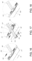
- the first driving member A1 can be arranged on the first end portion of the first working member 211, and the second driving member A2 can be arranged on the second end portion of the first working member 211; similarly, as shown in FIG. 17 and FIG. 18 , the first driving member A1 can be arranged on the first end portion of the second working member 213, and the second driving member A2 can be arranged on the second end portion of the second working member 213.
- the first working member 211, the second working member 62, the third working member 246, the fourth working member 250, the fifth working member 252, the sixth working member 254 and the auxiliary member 248 can be set in an initial mode, such as being located on an initial position; in the initial mode, any of the drawers can be pulled open, and the first working member 211 can be located on a first working position J1' and the second working member 213 can be located on a first preset position M1'.
- the first working member 211 can be driven by the first accessory W1 to shift from the first working position J1' to a second working position J2' in the first transverse direction T1 (which can be shown in FIG. 17 and FIG. 16 ), and the second accessory W2 of the second drawer 204b can be blocked by the second driving member A2 arranged on the first working member 211, so as to prevent the second drawer 204b from being shifted in the actuation direction D (which can be shown in FIG. 15 and FIG. 16 ).
- the second working member 213 can be driven by the first accessory W1 to move from the first preset position M1' to the second preset position M2' in the second transverse direction T2 (which can be shown in FIG. 17 and FIG. 18 ), and the third accessory W3 of the third drawer 204c can be blocked by the second driving member A2 arranged on the second working member 213 (which can be shown in FIG. 18 ), so as to prevent the third drawer 204c from being shifted in the actuation direction D.
- first working member 211 when first working member 211 is shifted to the second working position J2' in the first transverse direction T1, the first working member 211 can drive the third working member 246 (which can be shown in FIG. 16 ) to shift the auxiliary member 248 in a height direction U (which can be shown in FIG. 19 ), for further shifting the fourth working member 250 in the second transverse direction T2 (which can be shown in FIG. 20 ); the fourth accessory W4 of the fourth drawer 204d can be blocked by the first driving member A1 arranged on the fourth working member 250 (which can be shown in FIG. 13 and FIG. 14 ), so as to prevent the fourth drawer 204d from being shifted in the actuation direction D.
- the fourth working member 250 can drive the fifth working member 252 to shift in the second transverse direction T2, and the fifth accessory W5 of the fifth drawer 204e can be blocked by the first driving member A1 arranged on the fifth working member 252 (which can be shown in FIG. 15 ), so as to prevent the fifth drawer 204e from being shifted in the actuation direction D.
- the fifth working member 252 can shift the sixth working member 254 in the second transverse direction T2, and the sixth accessory W6 of the sixth drawer 204f can be blocked by the first driving member A1 arranged on the sixth working member 254 (which can be shown in FIG. 15 ), so as to prevent the sixth drawer 204f from being shifted in the actuation direction D.
- the slide rail mechanism provided by the embodiment of the present application can have following features: when the second rail 46 (or the related first drawer 24a) of the first slide rail assembly 26 is pulled open, the first working member 60 can be shifted in the first transverse direction T1 to block (or lock) the fourth rail 50 (or the related second drawer 24b) of the second slide rail assembly 28 arranged on an upright row of the first side of the cabinet 22; similarly, when the second rail 46 (or the related first drawer 24a) of the first slide rail assembly 26 is pulled open, the second working member 62 can be shifted in the second transverse direction T2 to block (or lock) the sixth rail 54 (or the third drawer 24c) of the third slide rail assembly 30 arranged on the upright row of the second side of the cabinet 22.
Landscapes
- Drawers Of Furniture (AREA)
- Seats For Vehicles (AREA)
Abstract
Description
- The present invention relates to a slide rail system according to the pre-characterizing clauses of claim 1.
- U.S. Patent No.
US 7,520,576B2 discloses an anti-tilt linkage mechanism that is applied for a vertical cabinet with several movable drawers. The vertical cabinet includes a file cabinet body, telescopic slide rails and two or more drawers. The telescopic slide rails are installed on the inner wall of the file cabinet body. The drawers are vertically installed inside the file cabinet body via the telescopic slide rails; when one drawer is pulled open, the other drawers cannot be pulled out from the file cabinet body. - However, the linkage mechanism of the foresaid patent is only suitable for two or more slide rails (or the related drawers) that are installed in a vertical manner. Design of a linkage product of satisfying market competition and different operation demands is an important issue in the institutional design industry.
- This in mind, the present invention aims at providing a slide rail system for solving above drawbacks.
- This is achieved by a slide rail system according to claim 1. The dependent claims pertain to corresponding further developments and improvements.
- As will be seen more clearly from the detailed description following below, the claimed a slide rail mechanism is configured to a cabinet. The slide rail mechanism includes a first slide rail assembly, a second slide rail assembly and a first working member. The first slide rail assembly and the second slide rail assembly are arranged on the cabinet. The first working member is shiftable with respect to the cabinet. The first slide rail assembly includes a first rail and a second rail. The second rail is shiftable with respect to the first rail in a longitudinal direction, and the second slide rail assembly includes a third rail and a fourth rail, and the fourth rail is shiftable with respect to the third rail in the longitudinal direction. When the second rail is shifted with respect to the first rail of the first slide rail assembly in an actuation direction, the first working member is driven to shift in a first transverse direction, so as to prevent the fourth rail from being shifted with respect to the third rail of the second slide rail assembly in the actuation direction.
- In the following, the invention is further illustrated by way of example, taking reference to the accompanying drawings. Thereof:
-
FIG. 1 is a diagram of furniture including a cabinet and a plurality of drawers according to a first embodiment of the present application, -
FIG. 2 is a diagram of a slide rail mechanism applied to the cabinet according to the first embodiment of the present application, -
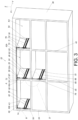
FIG. 3 is a diagram of the slide rail mechanism applied to the cabinet and the plurality of drawers according to the first embodiment of the present application, -
FIG. 4 is an enlarged diagram of an area A shown inFIG. 3 , -
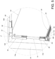
FIG. 5 is an enlarged diagram of an area B shown inFIG. 3 , -
FIG. 6 is an enlarged diagram of an area C shown inFIG. 3 , -
FIG. 7 is an enlarged diagram of an area D shown inFIG. 3 , -
FIG. 8 is a diagram of the cabinet and one pulled-open drawer according to the first embodiment of the present application, -
FIG. 9 is an enlarged diagram of an area E shown inFIG. 8 , -
FIG. 10 is an enlarged diagram of an area F shown inFIG. 8 , -
FIG. 11 is an enlarged diagram of an area G shown inFIG. 8 , -
FIG. 12 is an enlarged diagram of an area H shown inFIG. 8 , -
FIG. 13 is a diagram of furniture including the cabinet and the plurality of drawers according to a second embodiment of the present application, -
FIG. 14 is a diagram of the slide rail mechanism applied to the cabinet according to the second embodiment of the present application, -
FIG. 15 is a diagram of a part of the cabinet according to the second embodiment of the present application, -
FIG. 16 is an enlarged diagram of an area B' shown inFIG. 15 , -
FIG. 17 is an enlarged diagram of an area A' shown inFIG. 15 , -
FIG. 18 is an enlarged diagram of an area C' shown inFIG. 15 , -
FIG. 19 is an enlarged diagram of an area D' shown inFIG. 15 , and -
FIG. 20 is an enlarged diagram of an area E' shown inFIG. 15 . - Please refer to
FIG. 1 . In the first embodiment of the present application,furniture 20 can include acabinet 22, and thecabinet 22 can include a plurality of drawers arranged in a transverse direction (such as lateral arrangement) and a plurality of drawers arranged in a vertical direction, such as afirst drawer 24a, asecond drawer 24b, athird drawer 24c and afourth drawer 24d shown inFIG. 1 , and others are omitted herein for simplicity. The drawers can be pulled open and pushed into thecabinet 22. - Please refer to
FIG. 2 andFIG. 3 . A slide rail mechanism can be arranged inside thecabinet 22. The slide rail mechanism can include a plurality of slide rail assemblies, such as a firstslide rail assembly 26, a secondslide rail assembly 28, a thirdslide rail assembly 30 and a fourthslide rail assembly 32 respectively configured to hold thefirst drawer 24a, thesecond drawer 24b, thethird drawer 24c and thefourth drawer 24d. Each of the firstslide rail assembly 26, the secondslide rail assembly 28, the thirdslide rail assembly 30 and the fourthslide rail assembly 32 can include at least two slide rails being shiftable with respect to each other in a longitudinal direction. In the embodiment, the longitudinal direction can be defined as X-axis direction (or can be interpreted as a lengthwise direction or a shifting direction of the slide rail); the transverse direction can be defined as Y-axis direction (or can be interpreted as a lateral direction of the slide rail); a vertical direction can be defined as Z-axis direction (or can be interpreted as a height direction of the slide rail). - It should be mentioned that the first
slide rail assembly 26, the secondslide rail assembly 28, the thirdslide rail assembly 30 and the fourthslide rail assembly 32 can be designed as a pair of slide rails respectively arranged on the left side and the right side of the corresponding drawer. Only parts of the foresaid pair of two slide rails, such as the firstslide rail assembly 26, the secondslide rail assembly 28, the thirdslide rail assembly 30 and the fourthslide rail assembly 32 can be shown inFIG. 2 andFIG. 3 . - The
cabinet 22 can include a plurality of stand walls, such as a firstlateral wall 34, a secondlateral wall 36, afirst middle wall 38 and asecond middle wall 40. Thefirst middle wall 38 and thesecond middle wall 40 can be located between the firstlateral wall 34 and the secondlateral wall 36. Thecabinet 22 can have some first spaces K1 located between the firstlateral wall 34 and thefirst middle wall 38. Thesecond drawer 24b can be accommodated inside one of the first spaces K1. Thecabinet 22 can further have some second spaces K2 located between thefirst middle wall 38 and thesecond middle wall 40. Thefirst drawer 24a and thefourth drawer 24d can be accommodated inside two of the second spaces K2. Thecabinet 22 can further have some third space K3 located between thesecond middle wall 40 and the secondlateral wall 36. Thethird drawer 24c can be accommodated inside one of the third spaces K3. - The first
slide rail assembly 26, the secondslide rail assembly 28, the thirdslide rail assembly 30 and the fourthslide rail assembly 32 can be arranged inside thecabinet 22. The firstslide rail assembly 26, the secondslide rail assembly 28 and the thirdslide rail assembly 30 can be transversely arranged inside thecabinet 22. In addition, the fourthslide rail assembly 32 and the firstslide rail assembly 26 can be vertically arranged inside thecabinet 22. - The first
slide rail assembly 26 can include afirst rail 44 and asecond rail 46. Thesecond rail 46 can be shiftable with respect to thefirst rail 44 in the longitudinal direction. The secondslide rail assembly 28 can include athird rail 48 and afourth rail 50. Thefourth rail 50 can be shiftable with respect to thethird rail 48 in the longitudinal direction. Moreover, the thirdslide rail assembly 30 can include afifth rail 52 and asixth rail 54. Thesixth rail 54 can be shiftable with respect to thefifth rail 52 in the longitudinal direction. The fourthslide rail assembly 32 can include aseventh rail 56 and aneighth rail 58. Theeighth rail 58 can be shiftable with respect to theseventh rail 56 in the longitudinal direction. Thefirst rail 44 of the firstslide rail assembly 26, thethird rail 48 of the secondslide rail assembly 28, thefifth rail 52 of the thirdslide rail assembly 30, and theseventh rail 56 of the fourthslide rail assembly 32 can be mounted on thecabinet 22, such as in a fixed manner. Thesecond rail 46 of the firstslide rail assembly 26, thefourth rail 50 of the secondslide rail assembly 28, thesixth rail 54 of the thirdslide rail assembly 30, and theeighth rail 58 of the fourthslide rail assembly 32 can be respectively configured to hold thefirst drawer 24a, thesecond drawer 24b, thethird drawer 24c and thefourth drawer 24d. Preferably, each of the firstslide rail assembly 26, the secondslide rail assembly 28, the thirdslide rail assembly 30 and the fourthslide rail assembly 32 can further include a middle rail; that is to say, all the firstslide rail assembly 26, the secondslide rail assembly 28, the thirdslide rail assembly 30 and the fourthslide rail assembly 32 can be the three-rail slide rail assembly. For example, the middle rail of the firstslide rail assembly 26 can be movably mounted between thefirst rail 44 and thesecond rail 46. - Please refer to
FIG. 3 to FIG. 6 . The slide rail mechanism can further include a first workingmember 60, and may preferably further include a second workingmember 62. In one possible example, each of the first workingmember 60 and the second workingmember 62 can be a rod, arrangement directions of the first workingmember 60 and the second workingmember 62 can be parallel to the transverse direction of the slide rail, and the first workingmember 60 and the second workingmember 62 can be shiftable with respect to thecabinet 22. The first workingmember 60 and the second workingmember 62 can be set in an initial mode; for example, the first workingmember 60 can be located on a first working position J1, and the second workingmember 62 can be located on a first preset position M1. - Preferably, the first working
member 60 and the second workingmember 62 can be shiftable with respect to thecabinet 22 in the transverse direction. Therefore, moving directions of the first workingmember 60 and the second workingmember 62 can be substantially the same as the transverse direction (or the lateral direction) of the slide rail. - Preferably, the first working
member 60 and the second workingmember 62 can be mounted on thecabinet 22 via a casing (which is not shown in the figures), so as to increase motion stability of the first workingmember 60 and the second workingmember 62 with respect to thecabinet 22. - Preferably, each of the first working
member 60 and the second workingmember 62 can include two end portions. For example, the first workingmember 60 can include afirst end portion 60a and asecond end portion 60b opposite to each other, and the second workingmember 62 can include afirst end portion 62a and asecond end portion 62b opposite to each other. - Preferably, a first driving
member 64 can be arranged on thefirst end portion 60a of the first working member 60 (which can be shown inFIG. 4 ), and asecond driving member 66 can be arranged on thesecond end portion 60b of the first working member 60 (which can be shown inFIG. 5 ). Similarly, a third drivingmember 68 can be arranged on thefirst end portion 62a of the second working member 62 (which can be shown inFIG. 4 ), and a fourth drivingmember 70 can be arranged on thesecond end portion 62b of the second working member 62 (which can be shown inFIG. 6 ). - Preferably, most part of the first working
member 60 can be located inside the first space K1. The cabinet 22 (or the first middle wall 38) can include a first hole H1 connected between the first space K1 and the second space K2 (which can be shown inFIG. 4 ), and other part (such as thefirst end portion 60a and the first driving member 64) of the first workingmember 60 can pass through the first hole H1 to enter the second space K2. Similarly, most part of the second workingmember 62 can be located inside the second space K2. The cabinet 22 (or the second middle wall 40) can include a second hole H2 connected between the second space K2 and the third space K3 (which can be shown inFIG. 6 ), and other part (such as thesecond end portion 62b and the second driving member 70) of the second workingmember 62 can pass through the second hole H2 to enter the third space K3. - Preferably, the slide rail mechanism can further include a first
auxiliary member 72, a secondauxiliary member 74, a thirdauxiliary member 76 and a fourthauxiliary member 78. Each of the firstauxiliary member 72, the secondauxiliary member 74, the thirdauxiliary member 76 and the fourthauxiliary member 78 can be the rod. In one possible example, arrangement directions of the firstauxiliary member 72, the secondauxiliary member 74, the thirdauxiliary member 76 and the fourthauxiliary member 78 can be parallel to the height direction of the slide rail, and the firstauxiliary member 72, the secondauxiliary member 74, the thirdauxiliary member 76 and the fourthauxiliary member 78 can be shiftable with respect to thecabinet 22. - Preferably, the first
auxiliary member 72, the secondauxiliary member 74, the thirdauxiliary member 76 and the fourthauxiliary member 78 can be vertically shiftable with respect to thecabinet 22; that is to say, moving directions of the firstauxiliary member 72, the secondauxiliary member 74, the thirdauxiliary member 76 and the fourthauxiliary member 78 can be substantially the same as the height direction of the slide rail. - Preferably, the first
auxiliary member 72, the secondauxiliary member 74, the thirdauxiliary member 76 and the fourthauxiliary member 78 can be mounted on thecabinet 22 via at least one casing (which is not shown in the figures), so as to increase motion stability of the firstauxiliary member 72, the secondauxiliary member 74, the thirdauxiliary member 76 and the fourthauxiliary member 78 with respect to thecabinet 22. - Preferably, each of the first
auxiliary member 72, the secondauxiliary member 74, the thirdauxiliary member 76 and the fourthauxiliary member 78 can include two end portions. For example, the firstauxiliary member 72 can include afirst end portion 72a and asecond end portion 72b opposite to each other (which can be shown inFIG. 4 ), and the secondauxiliary member 74 can include afirst end portion 74a and asecond end portion 74b opposite to each other (which can be shown inFIG. 5 ), and the thirdauxiliary member 76 can include afirst end portion 76a and asecond end portion 76b opposite to each other (which can be shown inFIG. 6 ), and the fourthauxiliary member 78 can include afirst end portion 78a and asecond end portion 78b opposite to each other (which can be shown inFIG. 7 ). - Preferably, a
first stretching member 80 can be arranged on thefirst end portion 72a of the firstauxiliary member 72, and asecond stretching member 82 can be arranged on thesecond end portion 72b of the first auxiliary member 72 (which can be shown inFIG. 4 ); athird stretching member 84 can be arranged on thefirst end portion 74a of the secondauxiliary member 74, and afourth stretching member 86 can be arranged on thesecond end portion 74b of the second auxiliary member 74 (which can be shown inFIG. 5 ); afifth stretching member 88 can be arranged on thefirst end portion 76a of the thirdauxiliary member 76, and asixth stretching member 90 can be arranged on thesecond end portion 76b of the third auxiliary member 76 (which can be shown inFIG. 6 ); aseventh stretching member 92 can be arranged on thefirst end portion 78a of the fourthauxiliary member 78, and aneighth stretching member 94 can be arranged on thesecond end portion 78b of the fourth auxiliary member 78 (which can be shown inFIG. 7 ). Preferably, the cabinet 22 (or the first middle wall 38) can include a third hole H3 connected between two second spaces K2 and K2' (which can be shown inFIG. 7 ). - Preferably, at least one guiding portion can be arranged on the
first end portion 72a of the firstauxiliary member 72; for example, a first guidingportion 96 and asecond guiding portion 98 can be arranged on thefirst stretching member 80 of thefirst end portion 72a, and the first guidingportion 96 and the second guidingportion 98 can be an inclined typed structure or an arc typed structure (which can be shown inFIG. 4 ). Application of the first guidingportion 96 and the second guidingportion 98 is not limited to the foresaid embodiment, and depends on a design demand. In addition, the firstauxiliary member 72 can be movably mounted on thefirst rail 44 of the firstslide rail assembly 26 via thesecond stretching member 82. Moreover, a part of thesecond stretching member 82 arranged on thesecond end portion 72b of the firstauxiliary member 72 can pass through a first preset space Q1 formed on thefirst rail 44; thesecond stretching member 82 can include a first constrainingsection 100, and the first constrainingsection 100 can abut against an inner wall of thefirst rail 44 for blocking, so that the firstauxiliary member 72 can be shiftable with respect to thefirst rail 44 to an extreme position. Preferably, thesecond stretching member 82 can include afirst guiding feature 102, and thefirst guiding feature 102 can be applied to a firstcorresponding feature 104 of thesecond rail 46. Thefirst guiding feature 102 and the firstcorresponding feature 104 can be the inclined typed structure or the arc typed structure (which can be shown inFIG. 4 ); application of thefirst guiding feature 102 and the firstcorresponding feature 104 is not limited to the foresaid embodiment, and depends on the design demand. - Preferably, a guiding section can be arranged on the
first end portion 60a of the first workingmember 60. For example, the first drivingmember 64 arranged onfirst end portion 60a can have afirst guiding section 77; a guiding section can be arranged on thefirst end portion 62a of the second workingmember 62, for example, the third drivingmember 68 arranged on thefirst end portion 62a can have asecond guiding section 79. Thefirst guiding section 77 and thesecond guiding section 79 can be the inclined typed structure or the arc typed structure (which can be shown inFIG. 4 ); application of thefirst guiding section 77 and thesecond guiding section 79 is not limited to the foresaid embodiment, and depends on the design demand. - Preferably, at least one guiding portion can be arranged on the
first end portion 74a of the secondauxiliary member 74. For example, thethird stretching member 84 arranged on thefirst end portion 74a can have athird guiding portion 106. Thethird guiding portion 106 can be the inclined typed structure or the arc typed structure (which can be shown inFIG. 5 ); application of thethird guiding portion 106 is not limited to the foresaid embodiment, and depends on the design demand. In addition, the secondauxiliary member 74 can be movably mounted on thethird rail 48 of the secondslide rail assembly 28 via thefourth stretching member 86. Moreover, a part of thefourth stretching member 86 arranged on thesecond end portion 74b of the secondauxiliary member 74 can pass through a second preset space Q2 formed on thethird rail 48; thefourth stretching member 86 can include a second constrainingsection 108, and the second constrainingsection 108 can abut against an inner wall of thethird rail 48 for blocking, so that the secondauxiliary member 74 can be shiftable with respect to thethird rail 48 to the extreme position. Preferably, thefourth stretching member 86 can include asecond guiding feature 110, and thesecond guiding feature 110 can be applied to a secondcorresponding feature 112 of thefourth rail 50. Thesecond guiding feature 110 and the secondcorresponding feature 112 can be the inclined typed structure or the arc typed structure (which can be shown inFIG. 5 ); application of thesecond guiding feature 110 and the secondcorresponding feature 112 is not limited to the foresaid embodiment, and depends on the design demand. - Preferably, a guiding section can be arranged on the
second end portion 60b of the first workingmember 60. For example, the second drivingmember 66 arranged on thesecond end portion 60b can include athird guiding section 81, and thethird guiding section 81 can be the inclined typed structure or the arc typed structure (which can be shown inFIG. 5 ); application of thethird guiding section 81 is not limited to the foresaid embodiment, and depends on the design demand. - Preferably, at least one guiding portion can be arranged on the
first end portion 76a of the thirdauxiliary member 76. For example, the fifth stretchingmember 88 arranged on thefirst end portion 76a can include afourth guiding portion 114. Thefourth guiding portion 114 can be the inclined typed structure or the arc typed structure (which can be shown inFIG. 6 ); application of thefourth guiding portion 114 is not limited to the foresaid embodiment, and depends on the design demand. In addition, the thirdauxiliary member 76 can be movably mounted on thefifth rail 52 of the thirdslide rail assembly 30 via thesixth stretching member 90. Moreover, a part of the sixth stretchingmember 90 arranged on thesecond end portion 76b of the thirdauxiliary member 76 can pass through a third preset space Q3 formed on thefifth rail 52; thesixth stretching member 90 can include a third constrainingsection 116, and the third constrainingsection 116 can abut against an inner wall of thefifth rail 52 for blocking, so that the thirdauxiliary member 76 can be shiftable with respect to thefifth rail 52 to the extreme position. Preferably, thesixth stretching member 90 can include athird guiding feature 118, and thethird guiding feature 118 can be applied for a thirdcorresponding feature 120 of thesixth rail 54. The thirdcorresponding feature 120 and thethird guiding feature 118 can be the inclined typed structure or the arc typed structure (which can be shown inFIG. 6 ); application of the thirdcorresponding feature 120 and thethird guiding feature 118 is not limited to the foresaid embodiment, and depends on the design demand. - Preferably, a guiding section can be arranged on the
second end portion 62b of the second workingmember 62. For example, the fourth drivingmember 70 arranged on thesecond end portion 62b can include afourth guiding section 83, and thefourth guiding section 83 can be the inclined typed structure or the arc typed structure (which can be shown inFIG. 6 ); application of thefourth guiding section 83 is not limited to the foresaid embodiment, and depends on the design demand. - Preferably, a part of the seventh stretching
member 92 arranged on thefirst end portion 78a of the fourthauxiliary member 78 can pass through a first preset space Q1 formed on thefirst rail 44 of the firstslide rail assembly 26; a constrainingsection 122 can be arranged on the seventh stretchingmember 92 and can correspond to an inner wall of the first rail 44 (which can be shown inFIG. 7 ). Preferably, the eighth stretchingmember 94 arranged on thesecond end portion 78b of the fourthauxiliary member 78 can include afourth guiding feature 124, and thefourth guiding feature 124 can be applied for a fourthcorresponding feature 126 of theeighth rail 58. The fourthcorresponding feature 126 and thefourth guiding feature 124 can be the inclined typed structure or the arc typed structure (which can be shown inFIG. 7 ); application of the fourthcorresponding feature 126 and thefourth guiding feature 124 is not limited to the foresaid embodiment, and depends on the design demand. - Please refer to
FIG. 4 to FIG. 7 . Thefirst end portion 72a (where on thefirst stretching member 80 is disposed) of the firstauxiliary member 72 can correspond to somewhere between thefirst end portion 60a (where on the first drivingmember 64 is disposed) of the first workingmember 60 and thefirst end portion 62a (where on the third drivingmember 68 is disposed) of the second working member 62 (which can be shown inFIG. 4 ). Thefirst end portion 74a (where on thethird stretching member 84 is disposed) of the secondauxiliary member 74 can correspond to the second drivingmember 66 arranged on thesecond end portion 60b of the first working member 60 (which can be shown inFIG. 5 ). Thefirst end portion 76a (where on the fifth stretchingmember 88 is disposed) of the thirdauxiliary member 76 can correspond to thesecond end portion 62b (where on the fourth drivingmember 70 is disposed) of the second working member 62 (which can be shown inFIG. 6 ). - As shown in
FIG. 8 , all the drawers of thecabinet 22 can be retractable for being pulled open and pushed into thecabinet 22, that is to say, the slide rails of each slide rail assembly of thecabinet 22 can be set in a retractable state. When one of the drawers (such as thefirst drawer 24a or the slide rails of the related slide rail assembly) is pulled open in an actuation direction D, the other drawers (such as thesecond drawer 24b, thethird drawer 24c and thefourth drawer 24d) can be locked by the slide rail mechanism and cannot be pulled open with respect to thecabinet 22. - As shown in
FIG. 4 to FIG. 6 andFIG. 9 to FIG. 11 , when the second rail 46 (or thefirst drawer 24a) is shifted with respect to the first rail 44 (or the cabinet 22) of the firstslide rail assembly 26 from a first retracted position (as shown inFIG. 4 ) in the actuation direction D (which can be shown inFIG. 9 ), the first workingmember 60 can be driven to shift in a first transverse direction T1 (which can be shown inFIG. 9 andFIG. 10 ), so as to prevent thefourth rail 50 of the secondslide rail assembly 28 from being shifted with respect to thethird rail 48 from a second retracted position in the actuation direction D (which can be shown inFIG. 10 ). - Preferably, when the
second rail 46 is shifted with respect to thefirst rail 44 of the firstslide rail assembly 26 from the first retracted position (which can be shown inFIG. 4 ) in the actuation direction D, the second workingmember 62 can be driven to shift in a second transverse direction T2 (which can be shown inFIG. 9 andFIG. 11 ) opposite to the first transverse direction T1, so as to prevent thesixth rail 54 of the thirdslide rail assembly 30 from being shifted with respect to thefifth rail 52 from a third retracted position in the actuation direction (which can be shown inFIG. 11 ). - Preferably, when the
second rail 46 is shifted with respect to thefirst rail 44 of the firstslide rail assembly 26 from the first retracted position in the actuation direction D, thesecond rail 46 of the firstslide rail assembly 26 can drive the firstauxiliary member 72 to shift the first workingmember 60 and the second workingmember 62 respectively in the first transverse direction T1 and the second transverse direction T2 (which can be shown inFIG. 9 ), so as to prevent thefourth rail 50 of the secondslide rail assembly 28 from being shifted with respect to thethird rail 48 from the second retracted position in the actuation direction D (which can be shown inFIG. 10 ), and further to prevent thesixth rail 54 of the thirdslide rail assembly 30 from being shifted with respect to thefifth rail 52 from the third retracted position in the actuation direction D (which can be shown inFIG. 11 ). - For example, when the second rail 46 is shifted with respect to the first rail 44 of the first slide rail assembly 26 from the first retracted position in the actuation direction D, the second rail 46 of the first slide rail assembly 26 can drive the first auxiliary member 72 to abut the first guiding portion 96 of the first stretching member 80 against the first guiding section 77 of the first driving member 64 arranged on the first working member 60 for generating a force and then driving the first working member 60 to shift in the first transverse direction T1 (which can be shown in
FIG. 9 andFIG. 10 ), and the first auxiliary member 72 can be further configured to abut the second guiding portion 98 of the first stretching member 80 against the second guiding section 79 of the third driving member 68 arranged on the second working member 62 for generating the force and then driving the second working member 62 to shift in the second transverse direction T2 (which can be shown inFIG. 9 andFIG. 11 ), so as to prevent the fourth rail 50 of the second slide rail assembly 28 from being shifted with respect to the third rail 48 from the second retracted position in the actuation direction D (which can be shown inFIG. 10 ), and further to prevent the sixth rail 54 of the third slide rail assembly 30 from being shifted with respect to the fifth rail 52 from the third retracted position in the actuation direction D (which can be shown inFIG. 11 ). - Preferably, when the second rail 46 is shifted with respect to the first rail 44 of the first slide rail assembly 26 from the first retracted position in the actuation direction D (which can be shown in
FIG. 9 ), the second rail 46 of the first slide rail assembly 26 can utilize relative contact between the first corresponding feature 104 and the first guiding feature 102 of the second stretching member 82 to generate the force for driving the first auxiliary member 72 to shift in a first height direction U1, and the first auxiliary member 72 can drive the first working member 60 to shift in the first transverse direction T1 (which can be shown inFIG. 9 andFIG. 10 ), so as to block a movement path of the second auxiliary member 74; for example, the second auxiliary member 74 may be blocked by the second driving member 66 arranged on the first working member 60 and cannot be shifted in the first height direction U1 (which can be shown inFIG. 10 ), and the fourth rail 50 of the second slide rail assembly 28 can be blocked by the second auxiliary member 74 to prevent the fourth rail 50 of the second slide rail assembly 28 from being shifted with respect to the third rail 48 from the second retracted position in the actuation direction D. Preferably, when the first working member 60 is shifted in the first transverse direction T1, the first working member 60 can utilize relative contact between a third guiding section 81 of the second driving member 66 and the third guiding portion 106 of the third stretching member 84 to press the second auxiliary member 74 in a second height direction U2 opposite to the first height direction U1 (which can be shown inFIG. 10 ). - Preferably, when the second rail 46 is shifted with respect to the first rail 44 of the first slide rail assembly 26 from the first retracted position in the actuation direction D (which can be shown in
FIG. 9 ), the second rail 46 of the first slide rail assembly 26 can utilize relative contact between the first corresponding feature 104 and the first guiding feature 102 of the second stretching member 82 to generate the force for driving the first auxiliary member 72 to shift the second working member 62 in the second transverse direction T2 (which can be shown inFIG. 9 andFIG. 11 ) and further to block the movement path of the third auxiliary member 76; for example, the third auxiliary member 76 can be blocked by the fourth driving member 70 arranged on the second working member 62 and cannot be shifted in the first height direction U1 (which can be shown inFIG. 11 ), and the sixth rail 54 of the third slide rail assembly 30 can be blocked by the third auxiliary member 76 to prevent the sixth rail 54 of the third slide rail assembly 30 from being shifted with respect to the fifth rail 52 from the third retracted position in the actuation direction D. Preferably, when the second working member 62 is shifted in the second transverse direction T2, the second working member 62 can utilize relative contact between the fourth guiding section 83 of the fourth driving member 70 and the fourth guiding portion 114 of the fifth stretching member 88 to press the third auxiliary member 76 in the second height direction U2 (which can be shown inFIG. 11 ). - As shown in
FIG. 7 andFIG. 12 , when the second rail 46 (and a middle rail 51) is shifted with respect to thefirst rail 44 of the firstslide rail assembly 26 from the first retracted position (which can be shown inFIG. 7 ) in the actuation direction D (which can be shown inFIG. 12 ), the movement path of the fourthauxiliary member 78 can be blocked by thesecond rail 46 of the firstslide rail assembly 26; for example, the fourth auxiliary member 78 (or the seventh stretching member 92) can be blocked by thesecond rail 46 or themiddle rail 51 of the firstslide rail assembly 26 and cannot be shifted in the first height direction U1 (which can be shown inFIG. 12 ), and theeighth rail 58 of the fourthslide rail assembly 32 can be blocked by the fourthauxiliary member 78, so as to prevent theeighth rail 58 of the fourthslide rail assembly 32 from being shifted with respect to theseventh rail 56 form a fourth retracted position in the actuation direction D (which can be shown inFIG. 12 ). - As shown in
FIG. 13 andFIG. 14 , the slide rail mechanism of a second embodiment of the present application can be applied for the cabinet. In the first embodiment, the slide rail mechanism can utilize a mode switching function of the rail (or the related drawer) of the slide rail assembly to lock the rail (or the related drawer) of another slide rail assembly; in the second embodiment, the slide rail mechanism can utilize a mode switching function of the drawer (or the related rail) to lock another drawer (or the related rail). - In the second embodiment of the present application,
furniture 200 can include acabinet 202, and the plurality of drawers can be arranged inside thecabinet 202 in the transverse direction (such as the lateral arrangement) and further in the vertical direction, such as afirst drawer 204a, asecond drawer 204b, athird drawer 204c, afourth drawer 204d, afifth drawer 204e and asixth drawer 204f, and others are omitted herein for simplicity. The drawers can be pulled open and pushed into thecabinet 202. - The slide rail mechanism can be arranged inside the
cabinet 202, and can include the plurality of slide rail assemblies configured to respectively hold thefirst drawer 204a, thesecond drawer 204b, thethird drawer 204c, thefourth drawer 204d, thefifth drawer 204e and thesixth drawer 204f, such as a firstslide rail assembly 206, a secondslide rail assembly 208, a thirdslide rail assembly 210, a fourthslide rail assembly 212, a fifthslide rail assembly 214 and a sixthslide rail assembly 216. The foresaidslide rail assemblies cabinet 202, and each of the foresaidslide rail assemblies - The slide rail mechanism can include a first working
member 211, and further preferably include a second workingmember 213. The first workingmember 211 and the second workingmember 213 can be shiftable with respect to thecabinet 202. - For example, the first
slide rail assembly 206 can include afirst rail 218 and asecond rail 220, and thesecond rail 220 can be shiftable with respect to thefirst rail 218 in the longitudinal direction. The secondslide rail assembly 208 can include athird rail 222 and afourth rail 224, and thefourth rail 224 can be shiftable with respect to thethird rail 222 in the longitudinal direction. The thirdslide rail assembly 210 can include afifth rail 226 and asixth rail 228, and thesixth rail 228 can be shiftable with respect to thefifth rail 226 in the longitudinal direction. The fourthslide rail assembly 212 can include aseventh rail 230 and aneighth rail 232, and theeighth rail 232 can be shiftable with respect to theseventh rail 230 in the longitudinal direction. The fifthslide rail assembly 214 can include aninth rail 234 and atenth rail 236, and thetenth rail 236 can be shiftable with respect to theninth rail 234 in the longitudinal direction. The sixthslide rail assembly 216 can include aneleventh rail 238 and atwelfth rail 240, and thetwelfth rail 240 can be shiftable with respect to theeleventh rail 238 in the longitudinal direction. - The
second rail 220 of the firstslide rail assembly 206, thefourth rail 224 of the secondslide rail assembly 208, thesixth rail 228 of the thirdslide rail assembly 210, theeighth rail 232 of the fourthslide rail assembly 212, thetenth rail 236 of the fifthslide rail assembly 214, and thetwelfth rail 240 of the sixthslide rail assembly 216 can be respectively configured to hold thefirst drawer 204a, thesecond drawer 204b, thethird drawer 204c, thefourth drawer 204d, thefifth drawer 204e and thesixth drawer 204f. - Preferably, a first accessory W1, a second accessory W2, a third accessory W3, a fourth accessory W4, a fifth accessory W5 and a sixth accessory W6 can be respectively arranged on the
first drawer 204a, thesecond drawer 204b, thethird drawer 204c, thefourth drawer 204d, thefifth drawer 204e and thesixth drawer 204f. Each of the foresaid accessories can have the same or similar structures. As an example of the first accessory W1, the first accessory W1 can be located on the bottom of thefirst drawer 204a, and includes afirst guiding portion 242 and asecond guiding portion 244. Thefirst guiding portion 242 and thesecond guiding portion 244 can be the inclined typed structure or the arc typed structure; application of thefirst guiding portion 242 and thesecond guiding portion 244 is not limited to the foresaid embodiment, and depends on the design demand. - Preferably, the slide rail mechanism can further include a third working
member 246, anauxiliary member 248, a fourth workingmember 250, a fifth workingmember 252 and a sixth workingmember 254, which are linked with at least one of the first workingmember 211 and the second workingmember 213. - Preferably, a first driving member A1 and a second driving member A2 can be respectively arranged on two ends of each of the first working
member 211, the second workingmember 62, the third workingmember 246, the fourth workingmember 250, the fifth workingmember 252, the sixth workingmember 254 and theauxiliary member 248. Each of the first driving member A1 and the second driving member A2 can have a first guiding section A11 and a second guiding section A22. The first guiding section A11 and the second guiding section A22 can be the inclined typed structure or the arc typed structure; application of the first guiding section A11 and the second guiding section A22 is not limited to the foresaid embodiment, and depends on the design demand (which can be shown inFIG. 14 ). Further, as shown inFIG. 16 and FIG. 17 , the first driving member A1 can be arranged on the first end portion of the first workingmember 211, and the second driving member A2 can be arranged on the second end portion of the first workingmember 211; similarly, as shown inFIG. 17 and FIG. 18 , the first driving member A1 can be arranged on the first end portion of the second workingmember 213, and the second driving member A2 can be arranged on the second end portion of the second workingmember 213. - When the
drawers cabinet 202, the first workingmember 211, the second workingmember 62, the third workingmember 246, the fourth workingmember 250, the fifth workingmember 252, the sixth workingmember 254 and theauxiliary member 248 can be set in an initial mode, such as being located on an initial position; in the initial mode, any of the drawers can be pulled open, and the first workingmember 211 can be located on a first working position J1' and the second workingmember 213 can be located on a first preset position M1'. - As shown in
FIG. 15 to FIG. 18 , when thefirst drawer 204a is shifted in the actuation direction D (which can be shown inFIG. 15 orFIG. 17 ), the first workingmember 211 can be driven by the first accessory W1 to shift from the first working position J1' to a second working position J2' in the first transverse direction T1 (which can be shown inFIG. 17 and FIG. 16 ), and the second accessory W2 of thesecond drawer 204b can be blocked by the second driving member A2 arranged on the first workingmember 211, so as to prevent thesecond drawer 204b from being shifted in the actuation direction D (which can be shown inFIG. 15 andFIG. 16 ). Preferably, the second workingmember 213 can be driven by the first accessory W1 to move from the first preset position M1' to the second preset position M2' in the second transverse direction T2 (which can be shown inFIG. 17 and FIG. 18 ), and the third accessory W3 of thethird drawer 204c can be blocked by the second driving member A2 arranged on the second working member 213 (which can be shown inFIG. 18 ), so as to prevent thethird drawer 204c from being shifted in the actuation direction D. - Preferably, when first working member 211 is shifted to the second working position J2' in the first transverse direction T1, the first working member 211 can drive the third working member 246 (which can be shown in
FIG. 16 ) to shift the auxiliary member 248 in a height direction U (which can be shown inFIG. 19 ), for further shifting the fourth working member 250 in the second transverse direction T2 (which can be shown inFIG. 20 ); the fourth accessory W4 of the fourth drawer 204d can be blocked by the first driving member A1 arranged on the fourth working member 250 (which can be shown inFIG. 13 andFIG. 14 ), so as to prevent the fourth drawer 204d from being shifted in the actuation direction D. When the fourth working member 250 is shifted in the second transverse direction T2, the fourth working member 250 can drive the fifth working member 252 to shift in the second transverse direction T2, and the fifth accessory W5 of the fifth drawer 204e can be blocked by the first driving member A1 arranged on the fifth working member 252 (which can be shown inFIG. 15 ), so as to prevent the fifth drawer 204e from being shifted in the actuation direction D. When the fifth working member 252 is shifted in the second transverse direction T2, the fifth working member 252 can shift the sixth working member 254 in the second transverse direction T2, and the sixth accessory W6 of the sixth drawer 204f can be blocked by the first driving member A1 arranged on the sixth working member 254 (which can be shown inFIG. 15 ), so as to prevent the sixth drawer 204f from being shifted in the actuation direction D. - Therefore, the slide rail mechanism provided by the embodiment of the present application can have following features: when the second rail 46 (or the related
first drawer 24a) of the firstslide rail assembly 26 is pulled open, the first workingmember 60 can be shifted in the first transverse direction T1 to block (or lock) the fourth rail 50 (or the relatedsecond drawer 24b) of the secondslide rail assembly 28 arranged on an upright row of the first side of thecabinet 22; similarly, when the second rail 46 (or the relatedfirst drawer 24a) of the firstslide rail assembly 26 is pulled open, the second workingmember 62 can be shifted in the second transverse direction T2 to block (or lock) the sixth rail 54 (or thethird drawer 24c) of the thirdslide rail assembly 30 arranged on the upright row of the second side of thecabinet 22.
Claims (15)
- A slide rail mechanism configured to a cabinet (22, 202), the slide rail mechanism comprising:a first slide rail assembly (26, 206) and a second slide rail assembly (28, 208) arranged on the cabinet (22, 202); andcharacterized in that the slide rail mechanism further comprises:a first working member (60, 211) shiftable with respect to the cabinet (22, 202);wherein the first slide rail assembly (26, 206) comprises a first rail (44, 218) and a second rail (46, 220), the second rail (46, 220) is shiftable with respect to the first rail (44, 218) in a longitudinal direction, the second slide rail assembly (28, 208) comprises a third rail (48, 222) and a fourth rail (50, 224), and the fourth rail (50, 224) is shiftable with respect to the third rail (48, 222) in the longitudinal direction;wherein when the second rail (46, 220) is shifted with respect to the first rail (44, 218) of the first slide rail assembly (26, 206) in an actuation direction (D), the first working member (60, 211) is driven to shift in a first transverse direction (T1), so as to prevent the fourth rail (50, 224) from being shifted with respect to the third rail (48, 222) of the second slide rail assembly (28, 208) in the actuation direction (D).
- The slide rail mechanism of claim 1, characterized in that the slide rail mechanism further comprises:a third slide rail assembly (30, 210) and a second working member (62, 213);wherein the third slide rail assembly (30, 210) is arranged on the cabinet (22, 202) and comprises a fifth rail (52, 226) and a sixth rail (54, 228), the sixth rail (54, 228) is shiftable with respect to the fifth rail (52, 226) in the longitudinal direction, the second working member (62, 213) is shiftable with respect to the cabinet (22, 202);wherein when the second rail (46, 220) is shifted with respect to the first rail (44, 218) of the first slide rail assembly (26, 206) in the actuation direction (D), the second working member (62, 213) is driven to shift in a second transverse direction (T2), so as to prevent the sixth rail (54, 228) from being shifted with respect to the fifth rail (52, 226) of the third slide rail assembly (30, 210) in the actuation direction (D);wherein the first transverse direction (T1) is opposite to the second transverse direction (T2).
- The slide rail mechanism of claim 2, characterized in that the slide rail mechanism further comprises:a first auxiliary member (72) shiftable with respect to the cabinet (22, 202);wherein when the second rail (46, 220) is shifted with respect to the first rail (44, 218) of the first slide rail assembly (26, 206) in the actuation direction (D), the second rail (46, 220) of the first slide rail assembly (26, 206) drives the first auxiliary member (72), and the first working member (60, 211) and the second working member (62, 213) are driven by the first auxiliary member (72) to respectively shift in the first transverse direction (T1) and the second transverse direction (T2), so as to prevent the fourth rail (50, 224) from being shifted with respect to the third rail (48, 222) of the second slide rail assembly (28, 208) in the actuation direction (D), and further prevent the sixth rail (54, 228) from being shifted with respect to the fifth rail (52, 226) of the third slide rail assembly (30, 210) in the actuation direction (D);wherein the first auxiliary member (72) is vertically shiftable with respect to the cabinet (22, 202).
- The slide rail mechanism of any of claims 1 to 3, characterized in that the first auxiliary member (72) has a first end portion (60a, 62a, 72a, 74a, 76a, 78a) and a second end portion (60b, 62b, 72b, 74b, 76b, 78b), a first stretching member (80) is arranged on the first end portion (60a, 62a, 72a, 74a, 76a, 78a) of the first auxiliary member (72), and a second stretching member (82) is arranged on the second end portion (60b, 62b, 72b, 74b, 76b, 78b) of the first auxiliary member (72), so that the first auxiliary member (72) is movably mounted on the first rail (44, 218) of the first slide rail assembly (26, 206) via the second stretching member (82).
- The slide rail mechanism of claim 4, characterized in that the first working member (60, 211) has a first end portion (60a, 62a, 72a, 74a, 76a, 78a) and a second end portion (60b, 62b, 72b, 74b, 76b, 78b), a first driving member (64, A1) is arranged on the first end portion (60a, 62a, 72a, 74a, 76a, 78a) of the first working member (60, 211), the first driving member (64, A1) has a first guiding section (77, A11) configured to be used with a first guiding portion (96, 242) of the first stretching member (80).
- The slide rail mechanism of any of claims 4 to 5, characterized in that the second working member (62, 213) has a first end portion (60a, 62a, 72a, 74a, 76a, 78a) and a second end portion (60b, 62b, 72b, 74b, 76b, 78b), a third driving member (68) is arranged on the first end portion (60a, 62a, 72a, 74a, 76a, 78a) of the second working member (62, 213), the third driving member (68) has a second guiding section (79, A22) configured to be used with a second guiding portion (98, 244) of the first stretching member (80).
- The slide rail mechanism of any of claims 3 to 6, characterized in that the slide rail mechanism further comprises:a second auxiliary member (74) shiftable with respect to the cabinet (22, 202);wherein when the second rail (46, 220) is shifted with respect to the first rail (44, 218) of the first slide rail assembly (26, 206) in the actuation direction (D), the second rail (46, 220) of the first slide rail assembly (26, 206) drives the first auxiliary member (72), and the first working member (60, 211) is driven by the first auxiliary member (72) to shift in the first transverse direction (T1), so as to block a movement path of the second auxiliary member (74) for further blocking the fourth rail (50, 224) of the second slide rail assembly (28, 208) by the second auxiliary member (74), and further to prevent the fourth rail (50, 224) from being shifted with respect to the third rail (48, 222) of the second slide rail assembly (28, 208) in the actuation direction (D);wherein the second auxiliary member (74) is vertically shiftable with respect to the cabinet (22, 202).
- The slide rail mechanism of claim 7, characterized in that the slide rail mechanism further comprises:a third auxiliary member (76) shiftable with respect to the cabinet (22, 202);wherein when the second rail (46, 220) is shifted with respect to the first rail (44, 218) of the first slide rail assembly (26, 206) in the actuation direction (D), the second rail (46, 220) of the first slide rail assembly (26, 206) drives the first auxiliary member (72), and the second working member (62, 213) is driven by the first auxiliary member (72) to shift in the second transverse direction (T2), so as to block a movement path of the third auxiliary member (76) for further blocking the sixth rail (54, 228) of the third slide rail assembly (30, 210) by the third auxiliary member (76), and further to prevent the sixth rail (54, 228) from being shifted with respect to the fifth rail (52, 226) of the third slide rail assembly (30, 210) in the actuation direction (D);wherein the third auxiliary member (76) is vertically shiftable with respect to the cabinet (22, 202).
- The slide rail mechanism of claim 8, characterized in that the slide rail mechanism further comprises:a fourth slide rail assembly (32, 212) and a fourth auxiliary member (78), the fourth slide rail assembly (32, 212) and the first slide rail assembly (26, 206) being vertically arranged on the cabinet (22, 202), the fourth slide rail assembly (32, 212) comprising a seventh rail (56, 230) and an eighth rail (58, 232), the eighth rail (58, 232) being shiftable with respect to the seventh rail (56, 230) in the longitudinal direction, and the fourth auxiliary member (78) being shiftable with respect to the cabinet (22, 202);wherein when the second rail (46, 220) is shifted with respect to the first rail (44, 218) of the first slide rail assembly (26, 206) in the actuation direction (D), the second rail (46, 220) of the first slide rail assembly (26, 206) blocks a movement path of the fourth auxiliary member (78) for further blocking the eighth rail (58, 232) of the fourth slide rail assembly (32, 212) by the fourth auxiliary member (78), so as to prevent the eighth rail (58, 232) from being shifted with respect to the seventh rail (56, 230) of the fourth slide rail assembly (32, 212) in the actuation direction (D);wherein the fourth auxiliary member (78) is vertically shiftable with respect to the cabinet (22, 202).
- The slide rail mechanism of any of claims 2 to 9, characterized in that the first slide rail assembly (26, 206), the second slide rail assembly (28, 208) and the third slide rail assembly (30, 210) are transversely arranged on the cabinet (22, 202).
- The slide rail mechanism of any of claims 1 to 10, characterized in that the second rail (46, 220) of the first slide rail assembly (26, 206) is configured to hold a first drawer (24a, 204a), and the fourth rail (50, 224) is configured to hold a second drawer (24b, 204b); a first accessory (W1) and a second accessory (W2) are respectively arranged on the first drawer (24a, 204a) and the second drawer (24b, 204b); when the first drawer (24a, 204a) is shifted in the actuation direction (D), the first working member (60, 211) is driven by the first accessory (W1) to shift in the first transverse direction (T1) for blocking the second accessory (W2) of the second drawer (24b, 204b), so as to prevent the second drawer (24b, 204b) from being shifted in the actuation direction (D).
- The slide rail mechanism of any of claims 2 to 10, characterized in that the second rail (46, 220) of the first slide rail assembly (26, 206) is configured to hold a first drawer (24a, 204a), the fourth rail (50, 224) is configured to hold a second drawer (24b, 204b), and the sixth rail (54, 228) is configured to hold a third drawer (24c, 204c); a first accessory (W1), a second accessory (W2) and a third accessory (W3) are respectively arranged on the first drawer (24a, 204a), the second drawer (24b, 204b) and the third drawer (24c, 204c); when the first drawer (24a, 204a) is shifted in the actuation direction (D), the second working member (62, 213) is driven by the first accessory (W1) to shift in the second transverse direction (T2) for blocking the third accessory (W3) of the third drawer (24c, 204c), so as to prevent the third drawer (24c, 204c) from being shifted in the actuation direction (D).
- The slide rail mechanism of claim 12, characterized in that the slide rail mechanism further comprises:a fourth slide rail assembly (32, 212), a third working member (246), an auxiliary member (248) and a fourth working member (250);wherein the fourth slide rail assembly (32, 212) comprises a seventh rail (56, 230) and an eighth rail (58, 232), the eighth rail (58, 232) is shiftable with respect to the seventh rail (56, 230), and the eighth rail (58, 232) is configured to hold a fourth drawer (24d, 204d); a fourth accessory (W4) is arranged on the fourth drawer (24d, 204d);wherein when the first drawer (24a, 204a) is shifted in the actuation direction (D), the first working member (60, 211) is driven by the first accessory (W1) to shift in the first transverse direction (T1), and the first working member (60, 211) drives the third working member (246) to shift in the first transverse direction (T1), so that the third working member (246) drives the auxiliary member (248) to shift in a height direction (U), for driving the fourth working member (250) to shift in the second transverse direction (T2) and further to block the fourth accessory (W4) of the fourth drawer (24d, 204d), so as to prevent the fourth drawer (24d, 204d) from being shifted in the actuation direction (D).
- The slide rail mechanism of claim 13, characterized in that the slide rail mechanism further comprises:a fifth slide rail assembly (214) and a fifth working member (252);wherein the fifth slide rail assembly (214) comprises a ninth rail (234) and a tenth rail (236), the tenth rail (236) is shiftable with respect to the ninth rail (234), and the tenth rail (236) is configured to hold a fifth drawer (204e); a fifth accessory (W5) is arranged on the fifth drawer (204e);wherein when the first drawer (24a, 204a) is shifted in the actuation direction (D), the first working member (60, 211) is driven by the first accessory (W1) to shift in the first transverse direction (T1), and the first working member (60, 211) drives the third working member (246) to shift in the first transverse direction (T1), so that the third working member (246) drives the auxiliary member (248) to shift in the height direction (U) for driving the fourth working member (250) to shift in the second transverse direction (T2), and the fourth working member (250) drives the fifth working member (252) to block the fifth accessory (W5) of the fifth drawer (204e), so as to prevent the fifth drawer (204e) from being shifted in the actuation direction (D).
- The slide rail mechanism of claim 14, characterized in that the slide rail mechanism further comprises:a sixth slide rail assembly (216) and a sixth working member (254);wherein the sixth slide rail assembly (216) comprises an eleventh rail (238) and a twelfth rail (240), the twelfth rail (240) is shiftable with respect to the eleventh rail (238), and the twelfth rail (240) is configured to hold a sixth drawer (204f); a sixth accessory (W6) is arranged on the sixth drawer (204f);wherein when the first drawer (24a, 204a) is shifted in the actuation direction (D), the first working member (60, 211) is driven by the first accessory (W1) to shift in the first transverse direction (T1), and the first working member (60, 211) drives the third working member (246) to shift in the first transverse direction (T1), so that the third working member (246) drives the auxiliary member (248) to shift in the height direction (U) for driving the fourth working member (250) to shift in the second transverse direction (T2), and the fourth working member (250) drives the fifth working member (252) for driving the sixth working member (254) to shift in the second transverse direction (T2), and therefore the sixth working member (254) blocks the sixth accessory (W6) of the sixth drawer (204f) to prevent the sixth drawer (204f) from being shifted in the actuation direction (D).
Applications Claiming Priority (1)
| Application Number | Priority Date | Filing Date | Title |
|---|---|---|---|
| TW112103214A TWI849709B (en) | 2023-01-19 | 2023-01-19 | Slide rail mechanism |
Publications (1)
| Publication Number | Publication Date |
|---|---|
| EP4403733A1 true EP4403733A1 (en) | 2024-07-24 |
Family
ID=87196498
Family Applications (1)
| Application Number | Title | Priority Date | Filing Date |
|---|---|---|---|
| EP23184152.9A Pending EP4403733A1 (en) | 2023-01-19 | 2023-07-07 | Slide rail mechanism |
Country Status (4)
| Country | Link |
|---|---|
| US (1) | US12369711B2 (en) |
| EP (1) | EP4403733A1 (en) |
| JP (1) | JP7481543B1 (en) |
| TW (1) | TWI849709B (en) |
Families Citing this family (1)
| Publication number | Priority date | Publication date | Assignee | Title |
|---|---|---|---|---|
| TWI822613B (en) * | 2023-03-16 | 2023-11-11 | 川湖科技股份有限公司 | Slide rail mechanism and adjustment device thereof |
Citations (5)
| Publication number | Priority date | Publication date | Assignee | Title |
|---|---|---|---|---|
| US2848293A (en) * | 1956-07-02 | 1958-08-19 | Bell Telephone Labor Inc | Mechanical interlock for cabinethoused apparatus-mounting frameworks |
| FR2240643A5 (en) * | 1973-08-07 | 1975-03-07 | Brm | Drawer locking system for furniture - co-operating lugs and cam grooves ensures that unopened drawers are locked |
| US3941441A (en) * | 1974-01-02 | 1976-03-02 | Steelcase Inc. | Drawer interlock system |
| US7520576B2 (en) | 2002-08-21 | 2009-04-21 | Compx International Inc. | Anti-tip interlocking linkage mechanism for vertical cabinets |
| ITAN20130080A1 (en) * | 2013-04-24 | 2014-10-25 | Stm S R L | CHEST OF DRAWERS WITH INTERLOCK SYSTEM FOR OVERLAPPED DRAWERS. |
Family Cites Families (20)
| Publication number | Priority date | Publication date | Assignee | Title |
|---|---|---|---|---|
| US1486094A (en) * | 1918-09-28 | 1924-03-04 | United Alloy Steel Corp | Sectional-case lock |
| US3767280A (en) * | 1972-03-14 | 1973-10-23 | Eddy Match Co Ltd | Locking system for filing cabinets |
| JPS5531952Y2 (en) | 1976-08-18 | 1980-07-30 | ||
| JPS6017021Y2 (en) | 1978-11-17 | 1985-05-25 | 三洋電機株式会社 | Lock device for pull-out product storage in vending machines |
| US4609233A (en) * | 1983-11-03 | 1986-09-02 | Timberline Supply, Ltd. | Furniture locking system |
| JPS6184977U (en) | 1984-11-09 | 1986-06-04 | ||
| US5352030A (en) * | 1992-09-11 | 1994-10-04 | Wolfgang Derle | Anti-tip device |
| JP2615350B2 (en) | 1993-10-07 | 1997-05-28 | 樋口金庫株式會社 | Vertical cabinet |
| US5634701A (en) * | 1994-08-31 | 1997-06-03 | Fireking International, Inc. | Multi-drawer cabinet having a drawer lock-out mechanism |
| JP3443760B2 (en) | 1995-04-06 | 2003-09-08 | 株式会社岡村製作所 | Locking device for multi-row multi-stage drawer cabinet |
| JP2708392B2 (en) | 1995-07-19 | 1998-02-04 | アジアエレクトロニクス株式会社 | Unit simultaneous drawer prevention device |
| ATE225453T1 (en) | 1996-07-12 | 2002-10-15 | Accuride Int Inc | LOCKING SYSTEM WITH ROD LOCK FOR DRAWERS |
| US6296332B1 (en) | 1996-07-12 | 2001-10-02 | Accuride International, Inc. | File interlock system and mechanism |
| US6254205B1 (en) * | 1999-02-02 | 2001-07-03 | Thomas Regout Usa Inc. | Rail assembly with homing device and interlock |
| JP2000282736A (en) | 1999-03-29 | 2000-10-10 | Kokuyo Co Ltd | Drawer locking apparatus |
| GB2380516B (en) | 2001-10-05 | 2005-07-27 | Accuride Int Ltd | Rear interlock |
| US7823992B2 (en) | 2007-12-19 | 2010-11-02 | King Slide Works Co., Ltd. | Drawer interlock mechanism |
| TWI700978B (en) * | 2019-04-23 | 2020-08-01 | 川湖科技股份有限公司 | Slide rail assembly |
| CN111839038B (en) * | 2019-04-24 | 2021-11-16 | 川湖科技股份有限公司 | Slide rail assembly |
| TWI699176B (en) * | 2019-05-27 | 2020-07-21 | 川湖科技股份有限公司 | Synchronization system, device and method for slide rail assembly |
-
2023
- 2023-01-19 TW TW112103214A patent/TWI849709B/en active
- 2023-05-18 US US18/198,849 patent/US12369711B2/en active Active
- 2023-06-06 JP JP2023093465A patent/JP7481543B1/en active Active
- 2023-07-07 EP EP23184152.9A patent/EP4403733A1/en active Pending
Patent Citations (5)
| Publication number | Priority date | Publication date | Assignee | Title |
|---|---|---|---|---|
| US2848293A (en) * | 1956-07-02 | 1958-08-19 | Bell Telephone Labor Inc | Mechanical interlock for cabinethoused apparatus-mounting frameworks |
| FR2240643A5 (en) * | 1973-08-07 | 1975-03-07 | Brm | Drawer locking system for furniture - co-operating lugs and cam grooves ensures that unopened drawers are locked |
| US3941441A (en) * | 1974-01-02 | 1976-03-02 | Steelcase Inc. | Drawer interlock system |
| US7520576B2 (en) | 2002-08-21 | 2009-04-21 | Compx International Inc. | Anti-tip interlocking linkage mechanism for vertical cabinets |
| ITAN20130080A1 (en) * | 2013-04-24 | 2014-10-25 | Stm S R L | CHEST OF DRAWERS WITH INTERLOCK SYSTEM FOR OVERLAPPED DRAWERS. |
Also Published As
| Publication number | Publication date |
|---|---|
| JP7481543B1 (en) | 2024-05-10 |
| TW202430083A (en) | 2024-08-01 |
| TWI849709B (en) | 2024-07-21 |
| JP2024102788A (en) | 2024-07-31 |
| US20240245213A1 (en) | 2024-07-25 |
| US12369711B2 (en) | 2025-07-29 |
Similar Documents
| Publication | Publication Date | Title |
|---|---|---|
| US12345075B2 (en) | Furniture assembly and interlock kit thereof | |
| TW202019322A (en) | Slide rail assembly | |
| EP4537705A1 (en) | Slide rail assembly | |
| EP4570126A1 (en) | Slide rail assembly | |
| EP4548808A1 (en) | Slide rail assembly | |
| EP4501174B1 (en) | Slide rail assembly | |
| JP7481543B1 (en) | Slide Rail Mechanism | |
| EP4403732B1 (en) | Slide rail mechanism | |
| JP2024115507A (en) | Slide Rail Mechanism | |
| EP4461160B1 (en) | Furniture assembly | |
| CN118415458A (en) | Sliding rail mechanism | |
| EP3387951A1 (en) | Clutch for furniture parts | |
| EP4480344A1 (en) | Slide rail assembly | |
| EP4581983B1 (en) | Slide rail mechanism | |
| EP3804565B1 (en) | Cabinet and slide rail kit thereof | |
| EP4736711A1 (en) | Slide rail assembly | |
| EP4616761B1 (en) | Slide rail mechanism | |
| SE547185C2 (en) | Locking arrangement for drawers in a cabinet, a cabinet comprising such arrangement and a drawer rail | |
| EP4635366B1 (en) | Slide rail assembly | |
| US20250089891A1 (en) | Slide rail assembly | |
| CN119145718A (en) | Furniture assembly and interlink lock kit thereof | |
| JP2026079670A (en) | Slide rail assembly | |
| CN120240808A (en) | Slide rail mechanism |
Legal Events
| Date | Code | Title | Description |
|---|---|---|---|
| PUAI | Public reference made under article 153(3) epc to a published international application that has entered the european phase |
Free format text: ORIGINAL CODE: 0009012 |
|
| STAA | Information on the status of an ep patent application or granted ep patent |
Free format text: STATUS: THE APPLICATION HAS BEEN PUBLISHED |
|
| AK | Designated contracting states |
Kind code of ref document: A1 Designated state(s): AL AT BE BG CH CY CZ DE DK EE ES FI FR GB GR HR HU IE IS IT LI LT LU LV MC ME MK MT NL NO PL PT RO RS SE SI SK SM TR |
|
| STAA | Information on the status of an ep patent application or granted ep patent |
Free format text: STATUS: REQUEST FOR EXAMINATION WAS MADE |
|
| 17P | Request for examination filed |
Effective date: 20240819 |
|
| RBV | Designated contracting states (corrected) |
Designated state(s): AL AT BE BG CH CY CZ DE DK EE ES FI FR GB GR HR HU IE IS IT LI LT LU LV MC ME MK MT NL NO PL PT RO RS SE SI SK SM TR |
|
| GRAP | Despatch of communication of intention to grant a patent |
Free format text: ORIGINAL CODE: EPIDOSNIGR1 |
|
| STAA | Information on the status of an ep patent application or granted ep patent |
Free format text: STATUS: GRANT OF PATENT IS INTENDED |
|
| GRAS | Grant fee paid |
Free format text: ORIGINAL CODE: EPIDOSNIGR3 |
|
| INTG | Intention to grant announced |
Effective date: 20260401 |
|
| GRAA | (expected) grant |
Free format text: ORIGINAL CODE: 0009210 |
|
| STAA | Information on the status of an ep patent application or granted ep patent |
Free format text: STATUS: THE PATENT HAS BEEN GRANTED |