EP4403732A1 - Slide rail mechanism - Google Patents
Slide rail mechanism Download PDFInfo
- Publication number
- EP4403732A1 EP4403732A1 EP23184137.0A EP23184137A EP4403732A1 EP 4403732 A1 EP4403732 A1 EP 4403732A1 EP 23184137 A EP23184137 A EP 23184137A EP 4403732 A1 EP4403732 A1 EP 4403732A1
- Authority
- EP
- European Patent Office
- Prior art keywords
- rail
- slide rail
- assembly
- rail assembly
- slide
- Prior art date
- Legal status (The legal status is an assumption and is not a legal conclusion. Google has not performed a legal analysis and makes no representation as to the accuracy of the status listed.)
- Granted
Links
Images






Classifications
-
- E—FIXED CONSTRUCTIONS
- E05—LOCKS; KEYS; WINDOW OR DOOR FITTINGS; SAFES
- E05B—LOCKS; ACCESSORIES THEREFOR; HANDCUFFS
- E05B65/00—Locks or fastenings for special use
- E05B65/46—Locks or fastenings for special use for drawers
- E05B65/462—Locks or fastenings for special use for drawers for two or more drawers
- E05B65/463—Drawer interlock or anti-tilt mechanisms, i.e. when one drawer is open, at least one of the remaining drawers is locked
- E05B65/464—Drawer interlock or anti-tilt mechanisms, i.e. when one drawer is open, at least one of the remaining drawers is locked comprising two or more lock elements aligned in end-to-end abutting relation
-
- A—HUMAN NECESSITIES
- A47—FURNITURE; DOMESTIC ARTICLES OR APPLIANCES; COFFEE MILLS; SPICE MILLS; SUCTION CLEANERS IN GENERAL
- A47B—TABLES; DESKS; OFFICE FURNITURE; CABINETS; DRAWERS; GENERAL DETAILS OF FURNITURE
- A47B88/00—Drawers for tables, cabinets or like furniture; Guides for drawers
- A47B88/40—Sliding drawers; Slides or guides therefor
- A47B88/44—Sequencing or synchronisation of drawer slides or functional units
- A47B88/447—Simultaneous movement of rails within drawer slides, i.e. with a coordination of movement with all rail elements moving at the same time
-
- A—HUMAN NECESSITIES
- A47—FURNITURE; DOMESTIC ARTICLES OR APPLIANCES; COFFEE MILLS; SPICE MILLS; SUCTION CLEANERS IN GENERAL
- A47B—TABLES; DESKS; OFFICE FURNITURE; CABINETS; DRAWERS; GENERAL DETAILS OF FURNITURE
- A47B88/00—Drawers for tables, cabinets or like furniture; Guides for drawers
- A47B88/40—Sliding drawers; Slides or guides therefor
- A47B88/44—Sequencing or synchronisation of drawer slides or functional units
- A47B88/443—Successive movement of rails within drawer slides, i.e. at least one rail element is not moving during the movement of other elements
-
- A—HUMAN NECESSITIES
- A47—FURNITURE; DOMESTIC ARTICLES OR APPLIANCES; COFFEE MILLS; SPICE MILLS; SUCTION CLEANERS IN GENERAL
- A47B—TABLES; DESKS; OFFICE FURNITURE; CABINETS; DRAWERS; GENERAL DETAILS OF FURNITURE
- A47B88/00—Drawers for tables, cabinets or like furniture; Guides for drawers
- A47B88/90—Constructional details of drawers
- A47B88/919—Accessories or additional elements for drawers, e.g. drawer lighting
-
- A—HUMAN NECESSITIES
- A47—FURNITURE; DOMESTIC ARTICLES OR APPLIANCES; COFFEE MILLS; SPICE MILLS; SUCTION CLEANERS IN GENERAL
- A47B—TABLES; DESKS; OFFICE FURNITURE; CABINETS; DRAWERS; GENERAL DETAILS OF FURNITURE
- A47B2210/00—General construction of drawers, guides and guide devices
- A47B2210/0002—Guide construction for drawers
- A47B2210/0051—Guide position
- A47B2210/0059—Guide located at the side of the drawer
Definitions
- the present invention relates to a slide rail system according to the pre-characterizing clauses of claim 1.
- U.S. Patent No. US 7,520,576B2 discloses an anti-tilt linkage mechanism that is applied for a vertical cabinet with several movable drawers.
- the vertical cabinet includes a file cabinet body, telescopic slide rails and two or more drawers.
- the telescopic slide rails are installed on the inner wall of the file cabinet body.
- the drawers are vertically installed inside the file cabinet body via the telescopic slide rails; when one drawer is pulled open, the other drawers cannot be pulled out from the file cabinet body.
- the linkage mechanism of the foresaid patent is only suitable for two or more slide rails (or the related drawers) that are installed in a vertical manner. Design of a linkage product of satisfying market competition and different operation demands is an important issue in the institutional design industry.
- the present invention aims at providing a slide rail system for solving above drawbacks.
- the claimed slide rail mechanism is configured to a cabinet, and the cabinet has a wall with a first side and a second side opposite to each other.
- the slide rail mechanism includes a first slide rail assembly, a second slide rail assembly and a working member.
- the first slide rail assembly is arranged on the first side of the wall.
- the first slide rail assembly includes a first rail and a second rail, and the second rail is shifted with respect to the first rail in a longitudinal direction.
- the second slide rail assembly is arranged on the second side of the wall.
- the second slide rail assembly includes a third rail and a fourth rail. The fourth rail is shifted with respect to the third rail in the longitudinal direction.
- the working member is movably mounted on the wall.
- the second rail is configured to move back into the first rail of the first slide rail assembly
- the fourth rail is configured to move back into the third rail of the second slide rail assembly.
- furniture 20 can include a cabinet 22, and the cabinet 22 can have a plurality of drawers; for example, the cabinet 22 can at least include a first drawer 24a and a second drawer 24b, and may preferably further include a third drawer 24c and a fourth drawer 24d.
- the plurality of drawers can be accommodated inside the cabinet 22.
- the first drawer 24a and the second drawer 24b can be set as a first transverse row (or can be defined as a first lateral row).
- the third drawer 24c and the fourth drawer 24d can be set as a second transverse row (or can be defined as a second lateral row).
- the first drawer 24a and the third drawer 24c can be set as a first upright row.
- the second drawer 24b and the fourth drawer 24d can be set as a second upright row.
- the cabinet 22 can include a slide rail mechanism, and the slide rail mechanism can include a plurality of slide rail assemblies, such as a first slide rail assembly 26, a second slide rail assembly 28, a third slide rail assembly 30 and a fourth slide rail assembly 32 respectively configured to hold the first drawer 24a, the second drawer 24b, the third drawer 24c and the fourth drawer 24d.
- Each of the first slide rail assembly 26, the second slide rail assembly 28, the third slide rail assembly 30 and the fourth slide rail assembly 32 can include at least two slide rails capable of being shifted with respect to each other in a longitudinal direction.
- the longitudinal direction can be defined as X-axis direction, or can be interpreted as a lengthwise direction or a shifting direction of the slide rail;
- a transverse direction can be defined as Y-axis direction, or can be interpreted as a lateral direction of the slide rail;
- a vertical direction can be defined as Z-axis direction, or can be interpreted as a height direction of the slide rail.
- first slide rail assembly 26, the second slide rail assembly 28, the third slide rail assembly 30 and the fourth slide rail assembly 32 can be designed as a pair of two slide rails and respectively mounted on the left side and the right side of the corresponding drawer; however, parts of the foresaid pair of two slide rails, such as the first slide rail assembly 26, the second slide rail assembly 28, the third slide rail assembly 30 and the fourth slide rail assembly 32, are shown in FIG. 2 and FIG. 3 for easy understanding of the embodiment.
- the cabinet 22 can include a plurality of walls, such as first lateral wall 34, a second lateral wall 36, and a middle wall (which is named as the wall 38 in the following description).
- the wall 38 can be located between the first lateral wall 34 and the second lateral wall 36.
- the cabinet 22 can have a first space K1 located between the first lateral wall 34 and the wall 38 and configured to accommodate the first drawer 24a and the third drawer 24c, and further have a second space K2 located between the second lateral wall 36 and the wall 38 and configured to accommodate the second drawer 24b and the fourth drawer 24d.
- the wall 38 can have a first side S 1 and a second side S2 opposite to each other.
- the slide rail mechanism can further include a working member 40 movably mounted on the wall 38.
- the working member 40 can be connected to the wall 38 via a connection member 42; connection between the working member 40 and the wall 38 is not limited to the foresaid embodiment and depends on a design demand.
- the working member 40 may be connected to the wall 38 via any rotatable or pivotable structural members.
- the working member 40 can be preferably located on the top of the wall 38 of the cabinet 22 and near to the front end of the cabinet 22; position of the working member 40 is not limited to the foresaid embodiment and depends on the design demand.
- the working member 40 can include a first portion 44 and a second portion 46, and preferably further include a middle portion 48.
- the middle portion 48 can be connected between the first portion 44 and the second portion 46, and be arranged across the wall 38 in the transverse direction.
- the first portion 44 and the second portion 46 can be respectively bent from two opposite sides of the middle portion 48, such as bending from the sides of the middle portion 48 to ninety degrees.
- An actual value of the included angle between the middle portion 48 and each of the first portion 44 and the second portion 46 can depend on the design demand.
- the first portion 44 of the working member 40 can have a first guiding surface 50, and the second portion 46 of the working member 40 can have a second guiding surface 52 (which can be shown in FIG. 4 ).
- the working member 40 can have a first end 40a (such as the front end) and a second end 40b (such as the rear end).
- the first end 40a of the first portion 44 of the working member 40 can have a first height H1.
- the second end 40b of the first portion 44 of the working member 40 can have a second height H2.
- the second height H2 can be greater than the first height H1.
- the first guiding surface 50 can be formed due to height difference between the first height H1 and the second height H2.
- the first end 40a of the second portion 46 of the working member 40 can have a third height H3, and the second end 40b of the second portion 46 of the working member 40 can have a fourth height H4.
- the second guiding surface 52 can be formed due to height difference between the third height H3 and the fourth height H4.
- the first slide rail assembly 26 and the third slide rail assembly 30 can be arranged on the first side S1 of the wall 38, which means the first slide rail assembly 26 and the third slide rail assembly 30 are arranged on the same side of the wall 38 (which can be shown in FIG. 5 and FIG. 6 ).
- the second slide rail assembly 28 and the fourth slide rail assembly 32 can be arranged on the second side S2 of the wall 38 (which can be shown in FIG. 7 and FIG. 8 ).
- first slide rail assembly 26 can include a first rail 54 and a second rail 56.
- the second rail 56 can be shifted with respect to the first rail 54 in the longitudinal direction (which can be shown in FIG. 5 and FIG. 6 ).
- the second slide rail assembly 28 can include a third rail 58 and a fourth rail 60.
- the fourth rail 60 can be shifted with respect to the third rail 58 in the longitudinal direction (which can be shown in FIG. 7 and FIG. 8 ).
- a predefined height can be existed between the third slide rail assembly 30 and the first slide rail assembly 26, such as the Z-axis direction shown in FIG. 5 .
- the third slide rail assembly 30 can include a fifth rail 62 and a sixth rail 64, and the sixth rail 64 can be shifted with respect to the fifth rail 62 in the longitudinal direction (which can be shown in FIG. 5 ).
- the fourth slide rail assembly 32 can include a seventh rail 66 and an eighth rail 68. The eighth rail 68 can be shifted with respect to the seventh rail 66 in the longitudinal direction (which can be shown in FIG. 7 ).
- the first rail 54 of the first slide rail assembly 26 and the fifth rail 62 of the third slide rail assembly 30 can be mounted on (such as in a fixed manner) the first side S1 of the wall 38 (which can be shown in FIG. 5 and FIG. 6 ).
- the third rail 58 of the second slide rail assembly 28 and the seventh rail 66 of the fourth slide rail assembly 32 can be mounted on (such as in the fixed manner) the second side S2 of the wall 38 in the fixed manner (which can be shown in FIG. 7 and FIG. 8 ).
- each of the first slide rail assembly 26, the second slide rail assembly 28, the third slide rail assembly 30 and the fourth slide rail assembly 32 can include a middle rail.
- the middle rail 70 of the first slide rail assembly 26 can be movably mounted between the first rail 54 and the second rail 56
- the middle rail 72 of the second slide rail assembly 28 can be movably mounted between the third rail 58 and the fourth rail 60
- the middle rail 74 of the third slide rail assembly 30 can be movably mounted between the fifth rail 62 and the sixth rail 64
- the middle rail 76 of the fourth slide rail assembly 32 can be movably mounted between the seventh rail 66 and the eighth rail 68.
- the second rail 56 of the first slide rail assembly 26, the fourth rail 60 of the second slide rail assembly 28, the sixth rail 64 of the third slide rail assembly 30 and the eighth rail 68 of the fourth slide rail assembly 32 can be respectively configured to hold the first drawer 24a, the second drawer 24b, the third drawer 24c and the fourth drawer 24d as mentioned above.
- the second rail 56 can be moved back into the first rail 54 of the first slide rail assembly 26, and the fourth rail 60 can be moved back into the third rail 58 of the second slide rail assembly 28.
- the sixth rail 64 can be moved back into the fifth rail 62 of the third slide rail assembly 30, and the eighth rail 68 can be moved back into the seventh rail 66 of the fourth slide rail assembly 32.
- the second rail 56 when the second rail 56 is shifted with respect to the first rail 54 of the first slide rail assembly 26 from a retracted position (such as the embodiment shown in FIG. 5 and FIG. 6 ) in an actuation direction D, the second rail 56 can drive the working member 40 to switch from a first mode J1 (such as the embodiment shown in FIG. 5 to FIG. 8 ) to a second mode J2 (such as the embodiment shown in FIG. 9 to FIG.
- the first slide rail assembly 26 can further include first driving member 78 movably mounted on the first rail 54 (such as the embodiment shown in FIG. 5 and FIG. 6 or the embodiment shown in FIG. 9 and FIG. 10 ).
- the first rail 54 can include a first wall 55a (such as an upper wall) and a second wall 55b (such as lower wall).
- the first wall 55a can have a first hole Q1 where through the first driving member 78 is passed.
- the first driving member 78 of the first slide rail assembly 26 can include at least one first guiding structure 79 (which can be shown in FIG. 6 or FIG. 10 ), and the at least one first guiding structure 79 can be an arc surface or an inclined surface.
- the second slide rail assembly 28 can further include a first driving member 80 movably mounted on the third rail 58 (such as the embodiment shown in FIG. 7 and FIG. 8 or the embodiment shown in FIG. 11 and FIG. 12 ).
- the first driving member 80 of the second slide rail assembly 28 can include at least one first guiding structure 81 (which can be shown in FIG. 8 or FIG. 12 ), and the at least one first guiding structure 81 can be the arc surface or the inclined surface.
- the second rail 56 can drive the first driving member 78 of the first slide rail assembly 26 to abut against the first portion 44 of the working member 40 (which can be shown in FIG. 6 and FIG. 10 ), so as to switch the working member 40 from the first mode J1 (which can be shown in FIG. 6 ) to the second mode J2 (which can be shown in FIG. 10 ); therefore, the first driving member 80 of the second slide rail assembly 28 can be blocked by the second portion 46 of the working member 40 (which can be shown in FIG. 11 and FIG.
- the fourth rail 60 can be blocked by the first driving member 80 of the second slide rail assembly 28, so as to prevent the fourth rail 60 of the second slide rail assembly 28 from being shifted with respect to the third rail 58 in the actuation direction D (which can be shown in FIG. 11 and FIG. 12 ).
- the second rail 56 can include a first driving feature 82, and the first driving feature 82 can include a guiding portion 84 (which can be shown in FIG. 6 and FIG. 10 ), and the fourth rail 60 can include a first driving feature 86 (which can be shown in FIG. 8 and FIG. 12 );
- the first portion 44 of the working member 40 can be located on the first side S1 of the wall 38 (such as the embodiment shown in FIG. 5 and FIG. 6 or the embodiment shown in FIG. 9 and FIG. 10 ), and the second portion 46 of the working member 40 can be located on the second side S2 of the wall 38 (such as the embodiment shown in FIG. 7 and FIG. 8 or the embodiment shown in FIG. 11 and FIG. 12 ).
- the first driving feature 82 (or the related guiding portion 84) of the second rail 56 can drive the first driving member 78 of the first slide rail assembly 26 (which can be shown in FIG. 10 ), and the first guiding structure 79 of the first driving member 78 of the first slide rail assembly 26 can abut against the first guiding surface 50 of the first portion 44 of the working member 40 (which can be shown in FIG. 10 ), so as to switch the working member 40 from the first mode J1 (which can be shown in FIG. 5 to FIG. 8 ) to the second mode J2 (which can be shown in FIG. 9 to FIG.
- the first driving member 80 of the second slide rail assembly 28 can be blocked by the second guiding surface 52 of the second portion 46 of the working member 40 (which can be shown in FIG. 11 and FIG. 12 ), and the first driving feature 86 of the fourth rail 60 can be blocked by the first driving member 80 of the second slide rail assembly 28 (which can be shown in FIG. 12 ), so as to prevent the fourth rail 60 of the second slide rail assembly 28 from being shifted with respect to the third rail 58 in the actuation direction D (which can be shown in FIG. 11 and FIG. 12 ).
- the first slide rail assembly 26 can further include a second driving member 88 movably mounted on the first rail 54; for example, the second wall 55b of the first rail 54 can have a second hole Q2 where through the second driving member 88 is passed.
- the first driving member 78 and the second driving member 88 of the first slide rail assembly 26 can respectively include a first constraining portion 90 and a second constraining portion 92.
- the first constraining portion 90 can abut against an inner surface of the first wall 55a of the first rail 54, and the second constraining portion 92 can abut against an inner surface of the second wall 55b of the first rail 54, so that the first driving member 78 and the second driving member 88 of the first slide rail assembly 26 can be moved with respect to the first rail 54 to an extreme position (which can be shown in FIG. 9 and FIG. 10 ).
- the third slide rail assembly 30 can further include a first driving member 94 movably mounted on the fifth rail 62.
- Structural configuration of the first driving member 94 and the fifth rail 62 of the third slide rail assembly 30 can be substantially the same as structural configuration of the first driving member 78 and the first rail 54 of the first slide rail assembly 26, and a detailed description is omitted herein for simplicity.
- a rod member 96 can be arranged between the second driving member 88 of the first slide rail assembly 26 and the first driving member 94 of the third slide rail assembly 30 (which can be shown in FIG. 9 and FIG. 10 ); for example, the rod member 96 can be connected between the second driving member 88 of the first slide rail assembly 26 and the first driving member 94 of the third slide rail assembly 30.
- the slide rail mechanism of the present application can utilize a linkage mechanism to block the sixth rail 64 and therefore to prevent the sixth rail 64 of the third slide rail assembly 30 from being shifted with respect to the fifth rail 62 in the actuation direction D.
- a configuration direction of the linkage mechanism can be substantially the same as a height direction H of the wall 38.
- the linkage mechanism can include the second driving member 88 of the first slide rail assembly 26, the first driving member 94 of the third slide rail assembly 30, and the rod member 96.
- the second driving member 88 of the first slide rail assembly 26 can be blocked by the second rail 56 (or the middle rail 70) of the first slide rail assembly 26, so that the second driving member 88 of the first slide rail assembly 26 cannot be moved in the height direction H, and a first driving feature 98 of the sixth rail 64 can be blocked by the first driving member 94 of the third slide rail assembly 30, so as to prevent the sixth rail 64 of the third slide rail assembly 30 from being shifted with respect to the fifth rail 62 in the actuation direction D (which can be shown in FIG. 9 and FIG. 10 ).
- the structural configuration of the first driving feature 98 of the sixth rail 64 can be substantially the same as the structural configuration of the first driving feature 82 of the first rail 56, or substantially the same as the structural configuration of the first driving feature 86 of the fourth rail 60, and the detailed description is omitted herein for simplicity.
- the slide rail mechanism in the embodiment of the present application can provide following features:
Landscapes
- Drawers Of Furniture (AREA)
- Seats For Vehicles (AREA)
Abstract
Description
- The present invention relates to a slide rail system according to the pre-characterizing clauses of
claim 1. - U.S. Patent No.
US 7,520,576B2 discloses an anti-tilt linkage mechanism that is applied for a vertical cabinet with several movable drawers. The vertical cabinet includes a file cabinet body, telescopic slide rails and two or more drawers. The telescopic slide rails are installed on the inner wall of the file cabinet body. The drawers are vertically installed inside the file cabinet body via the telescopic slide rails; when one drawer is pulled open, the other drawers cannot be pulled out from the file cabinet body. - However, the linkage mechanism of the foresaid patent is only suitable for two or more slide rails (or the related drawers) that are installed in a vertical manner. Design of a linkage product of satisfying market competition and different operation demands is an important issue in the institutional design industry.
- This in mind, the present invention aims at providing a slide rail system for solving above drawbacks.
- This is achieved by a slide rail system according to
claim 1. The dependent claims pertain to corresponding further developments and improvements. - As will be seen more clearly from the detailed description following below, the claimed slide rail mechanism is configured to a cabinet, and the cabinet has a wall with a first side and a second side opposite to each other. The slide rail mechanism includes a first slide rail assembly, a second slide rail assembly and a working member. The first slide rail assembly is arranged on the first side of the wall. The first slide rail assembly includes a first rail and a second rail, and the second rail is shifted with respect to the first rail in a longitudinal direction. The second slide rail assembly is arranged on the second side of the wall. The second slide rail assembly includes a third rail and a fourth rail. The fourth rail is shifted with respect to the third rail in the longitudinal direction. The working member is movably mounted on the wall. The second rail is configured to move back into the first rail of the first slide rail assembly, and the fourth rail is configured to move back into the third rail of the second slide rail assembly. When the second rail is shifted with respect to the first rail of the first slide rail assembly in an actuation direction, the working member is driven by the second rail to switch from a first mode to a second mode, so as to prevent the fourth rail from being shifted with respect to the third rail of the second slide rail assembly in the actuation direction
- In the following, the invention is further illustrated by way of example, taking reference to the accompanying drawings. Thereof:
-
FIG. 1 is a diagram of furniture with a cabinet and a plurality of drawers according to an embodiment of the present application, -
FIG. 2 is a diagram of a plurality of slide rail assemblies arranged on a first side of a wall of the cabinet according to the embodiment of the present application, -
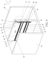
FIG. 3 is a diagram of a plurality of slide rail assemblies arranged on a second side of a wall of the cabinet according to the embodiment of the present application, -
FIG. 4 is a diagram of a working member according to the embodiment of the present application, -
FIG. 5 is a diagram of the plurality of slide rail assemblies arranged on the first side of the wall of the cabinet being in a retracted mode according to the embodiment of the present application, -
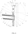
FIG. 6 is an enlarged diagram of an area A shown inFIG. 5 , -
FIG. 7 is a diagram of the plurality of slide rail assemblies arranged on the second side of the wall of the cabinet being in the retracted mode according to the embodiment of the present application, -
FIG. 8 is an enlarged diagram of the area A shown inFIG. 7 , -
FIG. 9 is a diagram of a second rail of a first slide rail assembly arranged on the first side of the wall of the cabinet being shiftable with respect to a first rail, and a third slide rail assembly arranged on the first side of the wall of the cabinet being in the retracted mode according to the embodiment of the present application, -
FIG. 10 is an enlarged diagram of the area A shown inFIG. 9 , -
FIG. 11 is a diagram of a second slide rail assembly and a fourth slide rail assembly arranged on the second side of the wall of the cabinet being in the retracted mode according to the embodiment of the present application, and -
FIG. 12 is an enlarged diagram of the area A shown inFIG. 11 . - Please refer to
FIG. 1 . In the embodiment of the present application,furniture 20 can include acabinet 22, and thecabinet 22 can have a plurality of drawers; for example, thecabinet 22 can at least include afirst drawer 24a and asecond drawer 24b, and may preferably further include athird drawer 24c and a fourth drawer 24d. The plurality of drawers can be accommodated inside thecabinet 22. Thefirst drawer 24a and thesecond drawer 24b can be set as a first transverse row (or can be defined as a first lateral row). Thethird drawer 24c and the fourth drawer 24d can be set as a second transverse row (or can be defined as a second lateral row). Thefirst drawer 24a and thethird drawer 24c can be set as a first upright row. Thesecond drawer 24b and the fourth drawer 24d can be set as a second upright row. - Please refer to
FIG. 2 andFIG. 3 . Thecabinet 22 can include a slide rail mechanism, and the slide rail mechanism can include a plurality of slide rail assemblies, such as a firstslide rail assembly 26, a secondslide rail assembly 28, a thirdslide rail assembly 30 and a fourthslide rail assembly 32 respectively configured to hold thefirst drawer 24a, thesecond drawer 24b, thethird drawer 24c and the fourth drawer 24d. Each of the firstslide rail assembly 26, the secondslide rail assembly 28, the thirdslide rail assembly 30 and the fourthslide rail assembly 32 can include at least two slide rails capable of being shifted with respect to each other in a longitudinal direction. In the embodiment, the longitudinal direction can be defined as X-axis direction, or can be interpreted as a lengthwise direction or a shifting direction of the slide rail; a transverse direction can be defined as Y-axis direction, or can be interpreted as a lateral direction of the slide rail; a vertical direction can be defined as Z-axis direction, or can be interpreted as a height direction of the slide rail. - It should be mentioned that the first
slide rail assembly 26, the secondslide rail assembly 28, the thirdslide rail assembly 30 and the fourthslide rail assembly 32 can be designed as a pair of two slide rails and respectively mounted on the left side and the right side of the corresponding drawer; however, parts of the foresaid pair of two slide rails, such as the firstslide rail assembly 26, the secondslide rail assembly 28, the thirdslide rail assembly 30 and the fourthslide rail assembly 32, are shown inFIG. 2 andFIG. 3 for easy understanding of the embodiment. - The
cabinet 22 can include a plurality of walls, such as firstlateral wall 34, a secondlateral wall 36, and a middle wall (which is named as thewall 38 in the following description). Thewall 38 can be located between the firstlateral wall 34 and the secondlateral wall 36. Thecabinet 22 can have a first space K1 located between the firstlateral wall 34 and thewall 38 and configured to accommodate thefirst drawer 24a and thethird drawer 24c, and further have a second space K2 located between the secondlateral wall 36 and thewall 38 and configured to accommodate thesecond drawer 24b and the fourth drawer 24d. Thewall 38 can have afirst side S 1 and a second side S2 opposite to each other. - Please refer to
FIG. 2 to FIG. 4 . The slide rail mechanism can further include a workingmember 40 movably mounted on thewall 38. In the embodiment, the workingmember 40 can be connected to thewall 38 via aconnection member 42; connection between the workingmember 40 and thewall 38 is not limited to the foresaid embodiment and depends on a design demand. In other possible embodiments, the workingmember 40 may be connected to thewall 38 via any rotatable or pivotable structural members. Besides, the workingmember 40 can be preferably located on the top of thewall 38 of thecabinet 22 and near to the front end of thecabinet 22; position of the workingmember 40 is not limited to the foresaid embodiment and depends on the design demand. - Preferably, the working
member 40 can include afirst portion 44 and asecond portion 46, and preferably further include amiddle portion 48. Themiddle portion 48 can be connected between thefirst portion 44 and thesecond portion 46, and be arranged across thewall 38 in the transverse direction. - Preferably, the
first portion 44 and thesecond portion 46 can be respectively bent from two opposite sides of themiddle portion 48, such as bending from the sides of themiddle portion 48 to ninety degrees. An actual value of the included angle between themiddle portion 48 and each of thefirst portion 44 and thesecond portion 46 can depend on the design demand. - Preferably, the
first portion 44 of the workingmember 40 can have afirst guiding surface 50, and thesecond portion 46 of the workingmember 40 can have a second guiding surface 52 (which can be shown inFIG. 4 ). - Preferably, as shown in
FIG. 4 , the workingmember 40 can have afirst end 40a (such as the front end) and asecond end 40b (such as the rear end). Thefirst end 40a of thefirst portion 44 of the workingmember 40 can have a first height H1. Thesecond end 40b of thefirst portion 44 of the workingmember 40 can have a second height H2. The second height H2 can be greater than the first height H1. Thefirst guiding surface 50 can be formed due to height difference between the first height H1 and the second height H2. In addition, thefirst end 40a of thesecond portion 46 of the workingmember 40 can have a third height H3, and thesecond end 40b of thesecond portion 46 of the workingmember 40 can have a fourth height H4. Thesecond guiding surface 52 can be formed due to height difference between the third height H3 and the fourth height H4. - Please refer to
FIG. 5 to FIG. 8 . The firstslide rail assembly 26 and the thirdslide rail assembly 30 can be arranged on the first side S1 of thewall 38, which means the firstslide rail assembly 26 and the thirdslide rail assembly 30 are arranged on the same side of the wall 38 (which can be shown inFIG. 5 andFIG. 6 ). The secondslide rail assembly 28 and the fourthslide rail assembly 32 can be arranged on the second side S2 of the wall 38 (which can be shown inFIG. 7 andFIG. 8 ). - Moreover, the first
slide rail assembly 26 can include afirst rail 54 and asecond rail 56. Thesecond rail 56 can be shifted with respect to thefirst rail 54 in the longitudinal direction (which can be shown inFIG. 5 andFIG. 6 ). The secondslide rail assembly 28 can include athird rail 58 and afourth rail 60. Thefourth rail 60 can be shifted with respect to thethird rail 58 in the longitudinal direction (which can be shown inFIG. 7 andFIG. 8 ). - A predefined height can be existed between the third
slide rail assembly 30 and the firstslide rail assembly 26, such as the Z-axis direction shown inFIG. 5 . The thirdslide rail assembly 30 can include afifth rail 62 and asixth rail 64, and thesixth rail 64 can be shifted with respect to thefifth rail 62 in the longitudinal direction (which can be shown inFIG. 5 ). The fourthslide rail assembly 32 can include aseventh rail 66 and aneighth rail 68. Theeighth rail 68 can be shifted with respect to theseventh rail 66 in the longitudinal direction (which can be shown inFIG. 7 ). - Preferably, the
first rail 54 of the firstslide rail assembly 26 and thefifth rail 62 of the thirdslide rail assembly 30 can be mounted on (such as in a fixed manner) the first side S1 of the wall 38 (which can be shown inFIG. 5 andFIG. 6 ). Thethird rail 58 of the secondslide rail assembly 28 and theseventh rail 66 of the fourthslide rail assembly 32 can be mounted on (such as in the fixed manner) the second side S2 of thewall 38 in the fixed manner (which can be shown inFIG. 7 andFIG. 8 ). - Preferably, each of the first
slide rail assembly 26, the secondslide rail assembly 28, the thirdslide rail assembly 30 and the fourthslide rail assembly 32 can include a middle rail. For example, themiddle rail 70 of the firstslide rail assembly 26 can be movably mounted between thefirst rail 54 and thesecond rail 56, themiddle rail 72 of the secondslide rail assembly 28 can be movably mounted between thethird rail 58 and thefourth rail 60, themiddle rail 74 of the thirdslide rail assembly 30 can be movably mounted between thefifth rail 62 and thesixth rail 64, and themiddle rail 76 of the fourthslide rail assembly 32 can be movably mounted between theseventh rail 66 and theeighth rail 68. - Preferably, the
second rail 56 of the firstslide rail assembly 26, thefourth rail 60 of the secondslide rail assembly 28, thesixth rail 64 of the thirdslide rail assembly 30 and theeighth rail 68 of the fourthslide rail assembly 32 can be respectively configured to hold thefirst drawer 24a, thesecond drawer 24b, thethird drawer 24c and the fourth drawer 24d as mentioned above. - The
second rail 56 can be moved back into thefirst rail 54 of the firstslide rail assembly 26, and thefourth rail 60 can be moved back into thethird rail 58 of the secondslide rail assembly 28. Thesixth rail 64 can be moved back into thefifth rail 62 of the thirdslide rail assembly 30, and theeighth rail 68 can be moved back into theseventh rail 66 of the fourthslide rail assembly 32. - As shown in
FIG. 5 to FIG. 8 and further shown inFIG. 9 to FIG. 12 , when thesecond rail 56 is shifted with respect to thefirst rail 54 of the firstslide rail assembly 26 from a retracted position (such as the embodiment shown inFIG. 5 andFIG. 6 ) in an actuation direction D, thesecond rail 56 can drive the workingmember 40 to switch from a first mode J1 (such as the embodiment shown inFIG. 5 to FIG. 8 ) to a second mode J2 (such as the embodiment shown inFIG. 9 to FIG. 12 ) in a pivotable manner or in a swayed manner, so as to prevent thefourth rail 60 of the secondslide rail assembly 28 from being shifted with respect to thethird rail 58 in the actuation direction D (such as the embodiment shown inFIG. 11 andFIG. 12 ). - Preferably, the first
slide rail assembly 26 can further include first drivingmember 78 movably mounted on the first rail 54 (such as the embodiment shown inFIG. 5 andFIG. 6 or the embodiment shown inFIG. 9 andFIG. 10 ). Thefirst rail 54 can include afirst wall 55a (such as an upper wall) and asecond wall 55b (such as lower wall). Thefirst wall 55a can have a first hole Q1 where through the first drivingmember 78 is passed. The first drivingmember 78 of the firstslide rail assembly 26 can include at least one first guiding structure 79 (which can be shown inFIG. 6 orFIG. 10 ), and the at least onefirst guiding structure 79 can be an arc surface or an inclined surface. Similarly, the secondslide rail assembly 28 can further include a first drivingmember 80 movably mounted on the third rail 58 (such as the embodiment shown inFIG. 7 andFIG. 8 or the embodiment shown inFIG. 11 andFIG. 12 ). The first drivingmember 80 of the secondslide rail assembly 28 can include at least one first guiding structure 81 (which can be shown inFIG. 8 orFIG. 12 ), and the at least onefirst guiding structure 81 can be the arc surface or the inclined surface. - When the
second rail 56 is shifted with respect to thefirst rail 54 of the firstslide rail assembly 26 in the actuation direction D, thesecond rail 56 can drive the first drivingmember 78 of the firstslide rail assembly 26 to abut against thefirst portion 44 of the working member 40 (which can be shown inFIG. 6 andFIG. 10 ), so as to switch the workingmember 40 from the first mode J1 (which can be shown inFIG. 6 ) to the second mode J2 (which can be shown inFIG. 10 ); therefore, the first drivingmember 80 of the secondslide rail assembly 28 can be blocked by thesecond portion 46 of the working member 40 (which can be shown inFIG. 11 andFIG. 12 ), and thefourth rail 60 can be blocked by the first drivingmember 80 of the secondslide rail assembly 28, so as to prevent thefourth rail 60 of the secondslide rail assembly 28 from being shifted with respect to thethird rail 58 in the actuation direction D (which can be shown inFIG. 11 andFIG. 12 ). - Preferably, the
second rail 56 can include afirst driving feature 82, and thefirst driving feature 82 can include a guiding portion 84 (which can be shown inFIG. 6 andFIG. 10 ), and thefourth rail 60 can include a first driving feature 86 (which can be shown inFIG. 8 andFIG. 12 ); thefirst portion 44 of the workingmember 40 can be located on the first side S1 of the wall 38 (such as the embodiment shown inFIG. 5 andFIG. 6 or the embodiment shown inFIG. 9 andFIG. 10 ), and thesecond portion 46 of the workingmember 40 can be located on the second side S2 of the wall 38 (such as the embodiment shown inFIG. 7 andFIG. 8 or the embodiment shown inFIG. 11 andFIG. 12 ). - When the second rail 56 of the first slide rail assembly 26 is shifted with respect to the first rail 54 from the retracted position in the actuation direction D, the first driving feature 82 (or the related guiding portion 84) of the second rail 56 can drive the first driving member 78 of the first slide rail assembly 26 (which can be shown in
FIG. 10 ), and the first guiding structure 79 of the first driving member 78 of the first slide rail assembly 26 can abut against the first guiding surface 50 of the first portion 44 of the working member 40 (which can be shown inFIG. 10 ), so as to switch the working member 40 from the first mode J1 (which can be shown inFIG. 5 to FIG. 8 ) to the second mode J2 (which can be shown inFIG. 9 to FIG. 12 ); therefore, the first driving member 80 of the second slide rail assembly 28 can be blocked by the second guiding surface 52 of the second portion 46 of the working member 40 (which can be shown inFIG. 11 andFIG. 12 ), and the first driving feature 86 of the fourth rail 60 can be blocked by the first driving member 80 of the second slide rail assembly 28 (which can be shown inFIG. 12 ), so as to prevent the fourth rail 60 of the second slide rail assembly 28 from being shifted with respect to the third rail 58 in the actuation direction D (which can be shown inFIG. 11 andFIG. 12 ). - Preferably, the first
slide rail assembly 26 can further include asecond driving member 88 movably mounted on thefirst rail 54; for example, thesecond wall 55b of thefirst rail 54 can have a second hole Q2 where through the second drivingmember 88 is passed. Besides, the first drivingmember 78 and the second drivingmember 88 of the firstslide rail assembly 26 can respectively include a first constrainingportion 90 and a second constrainingportion 92. The first constrainingportion 90 can abut against an inner surface of thefirst wall 55a of thefirst rail 54, and the second constrainingportion 92 can abut against an inner surface of thesecond wall 55b of thefirst rail 54, so that the first drivingmember 78 and the second drivingmember 88 of the firstslide rail assembly 26 can be moved with respect to thefirst rail 54 to an extreme position (which can be shown inFIG. 9 andFIG. 10 ). Similarly, the thirdslide rail assembly 30 can further include a first drivingmember 94 movably mounted on thefifth rail 62. Structural configuration of the first drivingmember 94 and thefifth rail 62 of the thirdslide rail assembly 30 can be substantially the same as structural configuration of the first drivingmember 78 and thefirst rail 54 of the firstslide rail assembly 26, and a detailed description is omitted herein for simplicity. Further, arod member 96 can be arranged between the second drivingmember 88 of the firstslide rail assembly 26 and the first drivingmember 94 of the third slide rail assembly 30 (which can be shown inFIG. 9 andFIG. 10 ); for example, therod member 96 can be connected between the second drivingmember 88 of the firstslide rail assembly 26 and the first drivingmember 94 of the thirdslide rail assembly 30. - When the
second rail 56 of the firstslide rail assembly 26 is shifted with respect to thefirst rail 54 in the actuation direction D, the slide rail mechanism of the present application can utilize a linkage mechanism to block thesixth rail 64 and therefore to prevent thesixth rail 64 of the thirdslide rail assembly 30 from being shifted with respect to thefifth rail 62 in the actuation direction D. In one possible embodiment, a configuration direction of the linkage mechanism can be substantially the same as a height direction H of thewall 38. The linkage mechanism can include the second drivingmember 88 of the firstslide rail assembly 26, the first drivingmember 94 of the thirdslide rail assembly 30, and therod member 96. - Moreover, when the
second rail 56 of the firstslide rail assembly 26 is shifted with respect to thefirst rail 54 in the actuation direction D, the second drivingmember 88 of the firstslide rail assembly 26 can be blocked by the second rail 56 (or the middle rail 70) of the firstslide rail assembly 26, so that the second drivingmember 88 of the firstslide rail assembly 26 cannot be moved in the height direction H, and afirst driving feature 98 of thesixth rail 64 can be blocked by the first drivingmember 94 of the thirdslide rail assembly 30, so as to prevent thesixth rail 64 of the thirdslide rail assembly 30 from being shifted with respect to thefifth rail 62 in the actuation direction D (which can be shown inFIG. 9 andFIG. 10 ). The structural configuration of thefirst driving feature 98 of thesixth rail 64 can be substantially the same as the structural configuration of thefirst driving feature 82 of thefirst rail 56, or substantially the same as the structural configuration of thefirst driving feature 86 of thefourth rail 60, and the detailed description is omitted herein for simplicity. - Therefore, the slide rail mechanism in the embodiment of the present application can provide following features:
- 1. when the second rail 56 (and the related
first drawer 24a) of the firstslide rail assembly 26 arranged on the first side S1 of thewall 38 of thecabinet 22 is pulled out with respect to the first rail 54 (or the related cabinet 22), the workingmember 40 can be utilized to prevent the fourth rail 60 (and the relatedsecond drawer 24b) of the secondslide rail assembly 28 arranged on the second side S2 of thewall 38 of thecabinet 22 from being pulled out with respect to the third rail 58 (or the related cabinet 22), so that the slide rail mechanism can lock the adjacent drawer in the transverse direction or in the lateral direction. - 2. preferably, when the second rail 56 (and the related
first drawer 24a) of the firstslide rail assembly 26 arranged on the first side S1 of thewall 38 of thecabinet 22 is pulled out with respect to the first rail 54 (or the related cabinet 22), the workingmember 40 can be utilized to prevent the sixth rail 64 (and the relatedthird drawer 24c) of the thirdslide rail assembly 30 arranged on the first side S1 of thewall 38 of thecabinet 22 from being pulled out with respect to the fifth rail 62 (or the related cabinet 22), so that the slide rail mechanism can lock the adjacent drawer in the height direction or in the vertical direction.
Claims (13)
- A slide rail mechanism configured to a wall (38) with a first side (S1) and a second side (S2) opposite to each other, the slide rail mechanism comprising:a first slide rail assembly (26) arranged on the first side (S 1) of the wall (38), the first slide rail assembly (26) comprising a first rail (54) and a second rail (56), and the second rail (56) being shiftable with respect to the first rail (54) in a longitudinal direction;a second slide rail assembly (28) arranged on the second side (S2) of the wall (38), the second slide rail assembly (28) comprising a third rail (58) and a fourth rail (60), and the fourth rail (60) being shifted with respect to the third rail (58) in the longitudinal direction;characterized in that the slide rail mechanism further comprises:
a working member (40) movably mounted on the wall (38). - The slide rail mechanism of claim 1, characterized in that the slide rail mechanism configured to a cabinet (22) having the wall (38), the second rail (56) is configured to move back into the first rail (54) of the first slide rail assembly (26), and the fourth rail (60) is configured to move back into the third rail (58) of the second slide rail assembly (28); when the second rail (56) is shifted with respect to the first rail (54) of the first slide rail assembly (26) in an actuation direction (D), the working member (40) is driven by the second rail (56) to switch from a first mode to a second mode, so as to prevent the fourth rail (60) from being shifted with respect to the third rail (58) of the second slide rail assembly (28) in the actuation direction (D).
- The slide rail mechanism of claim 1, characterized in that when the second rail (56) is shifted with respect to the first rail (54) of the first slide rail assembly (26) in an actuation direction (D), the working member (40) is driven by the second rail (56) to switch from a first mode to a second mode, so as to prevent the fourth rail (60) from being shifted with respect to the third rail (58) of the second slide rail assembly (28) in the actuation direction (D); the slide rail mechanism further comprises a third slide rail assembly (30) arranged on the first side (S1) of the wall (38), the third slide rail assembly (30) comprises a fifth rail (62) and a sixth rail (64), and the sixth rail (64) is shifted with respect to the fifth rail (62) in the longitudinal direction; when the second rail (56) is shifted with respect to the first rail (54) of the first slide rail assembly (26) in the actuation direction (D), the sixth rail (64) is blocked by a linkage mechanism to prevent the sixth rail (64) from being shifted with respect to the fifth rail (62) of the third slide rail assembly (30) in the actuation direction (D).
- The slide rail mechanism of claim 2, characterized in that the first slide rail assembly (26) further comprises a first driving member (78, 80, 94) movably mounted on the first rail (54); the second slide rail assembly (28) further comprises a first driving member (78, 80, 94) movably mounted on the third rail (58); the working member (40) comprises a first portion (44) and a second portion (46); when the second rail (56) is shifted with respect to the first rail (54) of the first slide rail assembly (26) in the actuation direction (D), the second rail (56) drives the first driving member (78, 80, 94) of the first slide rail assembly (26) to abut against the first portion (44) of the working member (40) for switching the working member (40) from the first mode to the second mode, so that the first driving member (78, 80, 94) of the second slide rail assembly (28) is blocked by the second portion (46) of the working member (40), and the fourth rail (60) is blocked by the first driving member (78, 80, 94) of second slide rail assembly (28), so as to prevent the fourth rail (60) from being shifted with respect to the third rail (58) of the second slide rail assembly (28) in the actuation direction (D).
- The slide rail mechanism of claim 4, characterized in that the second rail (56) comprises a first driving feature (82, 86, 98), and the fourth rail (60) comprises a first driving feature (82, 86, 98); the first portion (44) of the working member (40) is located on the first side (S 1) of the wall (38), and the second portion (46) of the working member (40) is located on the second side (S2) of the wall (38); when the second rail (56) is shifted with respect to the first rail (54) of the first slide rail assembly (26) in the actuation direction (D), the first driving feature (82, 86, 98) of the second rail (56) drives the first driving member (78, 80, 94) of the first slide rail assembly (26) to abut against the first portion (44) of the working member (40) for switching the working member (40) from the first mode to the second mode, so that the first driving member (78, 80, 94) of the second slide rail assembly (28) is blocked by the second portion (46) of the working member (40), and the first driving feature (82, 86, 98) of the fourth rail (60) is blocked by the first driving member (78, 80, 94) of the second slide rail assembly (28), so as to prevent the fourth rail (60) from being shifted with respect to the third rail (58) of the second slide rail assembly (28) in the actuation direction (D).
- The slide rail mechanism of any of claims 1 to 4, characterized in that the working member (40) further comprise a middle portion (48) connected between the first portion (44) and the second portion (46), and the middle portion (48) is arranged across the wall (38) in a transverse direction.
- The slide rail mechanism of any of claims 1 to 6, characterized in that the first portion (44) of the working member (40) has a first guiding surface (50), and the second portion (46) of the working member (40) has a second guiding surface (52).
- The slide rail mechanism of any of claims 1 to 7, characterized in that the working member (40) is connected to the wall (38) via a connection member (42).
- The slide rail mechanism of any of claims 1 to 8, characterized in that the slide rail mechanism further comprises a third slide rail assembly (30) arranged on the first side (S1) of the wall (38), a predefined height is existed between the third slide rail assembly (30) and the first slide rail assembly (26), the third slide rail assembly (30) comprises a fifth rail (62) and a sixth rail (64), and the sixth rail (64) is shifted with respect to the fifth rail (62) in the longitudinal direction.
- The slide rail mechanism of claim 9, characterized in that the first slide rail assembly (26) further comprises a second driving member (88) movably mounted on the first rail (54), the third slide rail assembly (30) further comprises a first driving member (78, 80, 94) movably mounted on the fifth rail (62), and a rod member (96) is arranged between the second driving member (88) of the first slide rail assembly (26) and the first driving member (78, 80, 94) of the third slide rail assembly (30); when the second rail (56) is shifted with respect to the first rail (54) of the first slide rail assembly (26) in the actuation direction (D), the second driving member (88) of the first slide rail assembly (26) is blocked by the second rail (56) of the first slide rail assembly (26), and a first driving feature (82, 86, 98) of the sixth rail (64) is blocked by the first driving member (78, 80, 94) of the third slide rail assembly (30), so as to prevent the sixth rail (64) of the third slide rail assembly (30) from being shifted with respect to the fifth rail (62) in the actuation direction (D).
- The slide rail mechanism of any of claims 1 to 10, characterized in that the first slide rail assembly (26) further comprises a middle rail (70, 72, 74, 76) movably mounted between the first rail (54) and the second rail (56), and the second slide rail assembly (28) further comprises a middle rail (70, 72, 74, 76) movably mounted between the third rail (58) and the fourth rail (60).
- The slide rail mechanism of any of claims 9 to 10, characterized in that the second rail (56) of the first slide rail assembly (26) is configured to hold a first drawer (24a), the fourth rail (60) of the second slide rail assembly (28) is configured to hold a second drawer (24b), and the sixth rail (64) of the third slide rail assembly (30) is configured to hold a third drawer (24c).
- The slide rail mechanism of any of claims 3 to 12, characterized in that an arrangement direction of the linkage mechanism is substantially the same as a height direction (H) of the wall (38), the linkage mechanism comprises two driving members (78, 80, 88, 94) and a rod member (96), the rod member (96) is arranged between the two driving members (78, 80, 88, 94); one of the two driving members (78, 80, 88, 94) is movably mounted on the first rail (54) of the first slide rail assembly (26), and the other driving member of the two driving members (78, 80, 88, 94) is movably mounted on the fifth rail (62) of the third slide rail assembly (30).
Applications Claiming Priority (1)
| Application Number | Priority Date | Filing Date | Title |
|---|---|---|---|
| TW112103213A TWI834485B (en) | 2023-01-19 | 2023-01-19 | Slide rail mechanism |
Publications (2)
| Publication Number | Publication Date |
|---|---|
| EP4403732A1 true EP4403732A1 (en) | 2024-07-24 |
| EP4403732B1 EP4403732B1 (en) | 2025-09-17 |
Family
ID=87196201
Family Applications (1)
| Application Number | Title | Priority Date | Filing Date |
|---|---|---|---|
| EP23184137.0A Active EP4403732B1 (en) | 2023-01-19 | 2023-07-07 | Slide rail mechanism |
Country Status (4)
| Country | Link |
|---|---|
| US (1) | US12318000B2 (en) |
| EP (1) | EP4403732B1 (en) |
| JP (1) | JP7471494B1 (en) |
| TW (1) | TWI834485B (en) |
Families Citing this family (1)
| Publication number | Priority date | Publication date | Assignee | Title |
|---|---|---|---|---|
| CN220889859U (en) * | 2023-08-28 | 2024-05-03 | 昆山湖华金属制品有限公司 | Interlink lock mechanism for multi-layer drawer furniture |
Citations (7)
| Publication number | Priority date | Publication date | Assignee | Title |
|---|---|---|---|---|
| JPS4985341U (en) * | 1972-11-02 | 1974-07-24 | ||
| DE2548373A1 (en) * | 1975-10-01 | 1977-04-07 | Schaerer Soehne Ag Muensingen | LOCKING DEVICE FOR PULL-OUTS IN A FRAME SIDE BY ONE |
| JPS5438866A (en) * | 1977-08-29 | 1979-03-24 | Nippon Filing Seizo Kk | Product housing shelf |
| JPH06154053A (en) * | 1992-11-19 | 1994-06-03 | Nec Eng Ltd | Simultaneous drawing-out preventing mechanism |
| JP2000291307A (en) * | 1999-04-01 | 2000-10-17 | Kyoei Ind Co Ltd | Simultaneous pullout preventive device of multi-row drawers |
| US7520576B2 (en) | 2002-08-21 | 2009-04-21 | Compx International Inc. | Anti-tip interlocking linkage mechanism for vertical cabinets |
| US20100148648A1 (en) * | 2008-12-15 | 2010-06-17 | Bush Industries, Inc. | Anti-Tip System For Adjacent Drawers |
Family Cites Families (18)
| Publication number | Priority date | Publication date | Assignee | Title |
|---|---|---|---|---|
| US4303288A (en) * | 1980-05-30 | 1981-12-01 | The Columbus Show Case Company | Drawer locking apparatus for merchandise cabinets |
| JPH07298938A (en) | 1994-05-09 | 1995-11-14 | Oki Electric Ind Co Ltd | Unit simultaneous drawing out preventing mechanism |
| ATE225453T1 (en) | 1996-07-12 | 2002-10-15 | Accuride Int Inc | LOCKING SYSTEM WITH ROD LOCK FOR DRAWERS |
| US6296332B1 (en) | 1996-07-12 | 2001-10-02 | Accuride International, Inc. | File interlock system and mechanism |
| US5931548A (en) * | 1997-02-18 | 1999-08-03 | Steelcase Inc. | Drawer interlock to non-interlock conversion device |
| JP2000282736A (en) | 1999-03-29 | 2000-10-10 | Kokuyo Co Ltd | Drawer locking apparatus |
| GB2380516B (en) * | 2001-10-05 | 2005-07-27 | Accuride Int Ltd | Rear interlock |
| TWM284291U (en) * | 2005-08-15 | 2006-01-01 | Nan Juen Int Co Ltd | Inter-locking, braking, wedging device of drawer |
| US7144092B1 (en) * | 2006-01-11 | 2006-12-05 | Ting-Wei Chang | Arresting apparatus of multilayer drawers |
| US20080061663A1 (en) * | 2006-09-08 | 2008-03-13 | Tsung-Che Wu | Drawer slide module structure |
| TWI297596B (en) * | 2006-09-21 | 2008-06-11 | Sun Chain Metal Industry Co Ltd | Interlocking device for a drawer guideway |
| US7823992B2 (en) | 2007-12-19 | 2010-11-02 | King Slide Works Co., Ltd. | Drawer interlock mechanism |
| US8109527B2 (en) * | 2008-02-21 | 2012-02-07 | Rubbermaid, Inc. | Medical cart and keyboard tray |
| TWI598026B (en) * | 2015-09-18 | 2017-09-01 | King Slide Works Co Ltd | Slide rail assembly with interlock device |
| US9788653B1 (en) * | 2017-06-05 | 2017-10-17 | James W. Lazenby | Method and apparatus for a transparent kitchen cabinet |
| JP2019132104A (en) | 2018-02-02 | 2019-08-08 | 株式会社オカムラ | Store fixture |
| CN112386025B (en) * | 2019-08-19 | 2023-04-18 | 川湖科技股份有限公司 | Sliding rail assembly |
| US20210230913A1 (en) * | 2020-01-27 | 2021-07-29 | Tiffin Metal Products Co. | Compartment locking system |
-
2023
- 2023-01-19 TW TW112103213A patent/TWI834485B/en active
- 2023-05-16 US US18/198,267 patent/US12318000B2/en active Active
- 2023-06-06 JP JP2023093347A patent/JP7471494B1/en active Active
- 2023-07-07 EP EP23184137.0A patent/EP4403732B1/en active Active
Patent Citations (7)
| Publication number | Priority date | Publication date | Assignee | Title |
|---|---|---|---|---|
| JPS4985341U (en) * | 1972-11-02 | 1974-07-24 | ||
| DE2548373A1 (en) * | 1975-10-01 | 1977-04-07 | Schaerer Soehne Ag Muensingen | LOCKING DEVICE FOR PULL-OUTS IN A FRAME SIDE BY ONE |
| JPS5438866A (en) * | 1977-08-29 | 1979-03-24 | Nippon Filing Seizo Kk | Product housing shelf |
| JPH06154053A (en) * | 1992-11-19 | 1994-06-03 | Nec Eng Ltd | Simultaneous drawing-out preventing mechanism |
| JP2000291307A (en) * | 1999-04-01 | 2000-10-17 | Kyoei Ind Co Ltd | Simultaneous pullout preventive device of multi-row drawers |
| US7520576B2 (en) | 2002-08-21 | 2009-04-21 | Compx International Inc. | Anti-tip interlocking linkage mechanism for vertical cabinets |
| US20100148648A1 (en) * | 2008-12-15 | 2010-06-17 | Bush Industries, Inc. | Anti-Tip System For Adjacent Drawers |
Also Published As
| Publication number | Publication date |
|---|---|
| JP7471494B1 (en) | 2024-04-19 |
| US20240245212A1 (en) | 2024-07-25 |
| TWI834485B (en) | 2024-03-01 |
| JP2024102787A (en) | 2024-07-31 |
| EP4403732B1 (en) | 2025-09-17 |
| TW202430082A (en) | 2024-08-01 |
| US12318000B2 (en) | 2025-06-03 |
Similar Documents
| Publication | Publication Date | Title |
|---|---|---|
| EP4477823A1 (en) | Interlock kit and related furniture assembly | |
| EP4403732B1 (en) | Slide rail mechanism | |
| US12203292B2 (en) | Slide rail mechanism | |
| EP4570126A1 (en) | Slide rail assembly | |
| EP4501174B1 (en) | Slide rail assembly | |
| EP4417088A1 (en) | Slide rail mechanism | |
| EP4461160B1 (en) | Furniture assembly | |
| EP4403733A1 (en) | Slide rail mechanism | |
| JP7592952B2 (en) | Slide Rail Mechanism | |
| EP4581983B1 (en) | Slide rail mechanism | |
| CN118452646A (en) | Slide rail mechanism | |
| US12628950B2 (en) | Slide rail assembly | |
| EP4523567A1 (en) | Slide rail assembly | |
| EP4736711A1 (en) | Slide rail assembly | |
| EP3804565A1 (en) | Cabinet and slide rail kit thereof | |
| CN106820676A (en) | installation mechanism | |
| CN120240808A (en) | Slide rail mechanism | |
| JP2026085216A (en) | Slide rail mechanism |
Legal Events
| Date | Code | Title | Description |
|---|---|---|---|
| PUAI | Public reference made under article 153(3) epc to a published international application that has entered the european phase |
Free format text: ORIGINAL CODE: 0009012 |
|
| STAA | Information on the status of an ep patent application or granted ep patent |
Free format text: STATUS: THE APPLICATION HAS BEEN PUBLISHED |
|
| STAA | Information on the status of an ep patent application or granted ep patent |
Free format text: STATUS: REQUEST FOR EXAMINATION WAS MADE |
|
| AK | Designated contracting states |
Kind code of ref document: A1 Designated state(s): AL AT BE BG CH CY CZ DE DK EE ES FI FR GB GR HR HU IE IS IT LI LT LU LV MC ME MK MT NL NO PL PT RO RS SE SI SK SM TR |
|
| 17P | Request for examination filed |
Effective date: 20240714 |
|
| RBV | Designated contracting states (corrected) |
Designated state(s): AL AT BE BG CH CY CZ DE DK EE ES FI FR GB GR HR HU IE IS IT LI LT LU LV MC ME MK MT NL NO PL PT RO RS SE SI SK SM TR |
|
| RIC1 | Information provided on ipc code assigned before grant |
Ipc: A47B 88/40 20170101ALI20250403BHEP Ipc: E05B 65/464 20170101AFI20250403BHEP |
|
| GRAP | Despatch of communication of intention to grant a patent |
Free format text: ORIGINAL CODE: EPIDOSNIGR1 |
|
| STAA | Information on the status of an ep patent application or granted ep patent |
Free format text: STATUS: GRANT OF PATENT IS INTENDED |
|
| INTG | Intention to grant announced |
Effective date: 20250509 |
|
| GRAS | Grant fee paid |
Free format text: ORIGINAL CODE: EPIDOSNIGR3 |
|
| GRAA | (expected) grant |
Free format text: ORIGINAL CODE: 0009210 |
|
| STAA | Information on the status of an ep patent application or granted ep patent |
Free format text: STATUS: THE PATENT HAS BEEN GRANTED |
|
| AK | Designated contracting states |
Kind code of ref document: B1 Designated state(s): AL AT BE BG CH CY CZ DE DK EE ES FI FR GB GR HR HU IE IS IT LI LT LU LV MC ME MK MT NL NO PL PT RO RS SE SI SK SM TR |
|
| REG | Reference to a national code |
Ref country code: GB Ref legal event code: FG4D |
|
| REG | Reference to a national code |
Ref country code: CH Ref legal event code: EP |
|
| REG | Reference to a national code |
Ref country code: DE Ref legal event code: R096 Ref document number: 602023006717 Country of ref document: DE |
|
| REG | Reference to a national code |
Ref country code: IE Ref legal event code: FG4D |
|
| PG25 | Lapsed in a contracting state [announced via postgrant information from national office to epo] |
Ref country code: NO Free format text: LAPSE BECAUSE OF FAILURE TO SUBMIT A TRANSLATION OF THE DESCRIPTION OR TO PAY THE FEE WITHIN THE PRESCRIBED TIME-LIMIT Effective date: 20251217 |
|
| REG | Reference to a national code |
Ref country code: LT Ref legal event code: MG9D |
|
| PG25 | Lapsed in a contracting state [announced via postgrant information from national office to epo] |
Ref country code: FI Free format text: LAPSE BECAUSE OF FAILURE TO SUBMIT A TRANSLATION OF THE DESCRIPTION OR TO PAY THE FEE WITHIN THE PRESCRIBED TIME-LIMIT Effective date: 20250917 |
|
| PG25 | Lapsed in a contracting state [announced via postgrant information from national office to epo] |
Ref country code: HR Free format text: LAPSE BECAUSE OF FAILURE TO SUBMIT A TRANSLATION OF THE DESCRIPTION OR TO PAY THE FEE WITHIN THE PRESCRIBED TIME-LIMIT Effective date: 20250917 |
|
| PG25 | Lapsed in a contracting state [announced via postgrant information from national office to epo] |
Ref country code: GR Free format text: LAPSE BECAUSE OF FAILURE TO SUBMIT A TRANSLATION OF THE DESCRIPTION OR TO PAY THE FEE WITHIN THE PRESCRIBED TIME-LIMIT Effective date: 20251218 |
|
| PG25 | Lapsed in a contracting state [announced via postgrant information from national office to epo] |
Ref country code: SE Free format text: LAPSE BECAUSE OF FAILURE TO SUBMIT A TRANSLATION OF THE DESCRIPTION OR TO PAY THE FEE WITHIN THE PRESCRIBED TIME-LIMIT Effective date: 20250917 |
|
| REG | Reference to a national code |
Ref country code: NL Ref legal event code: MP Effective date: 20250917 |
|
| PG25 | Lapsed in a contracting state [announced via postgrant information from national office to epo] |
Ref country code: LV Free format text: LAPSE BECAUSE OF FAILURE TO SUBMIT A TRANSLATION OF THE DESCRIPTION OR TO PAY THE FEE WITHIN THE PRESCRIBED TIME-LIMIT Effective date: 20250917 |
|
| PG25 | Lapsed in a contracting state [announced via postgrant information from national office to epo] |
Ref country code: BG Free format text: LAPSE BECAUSE OF FAILURE TO SUBMIT A TRANSLATION OF THE DESCRIPTION OR TO PAY THE FEE WITHIN THE PRESCRIBED TIME-LIMIT Effective date: 20250917 |
|
| PG25 | Lapsed in a contracting state [announced via postgrant information from national office to epo] |
Ref country code: RS Free format text: LAPSE BECAUSE OF FAILURE TO SUBMIT A TRANSLATION OF THE DESCRIPTION OR TO PAY THE FEE WITHIN THE PRESCRIBED TIME-LIMIT Effective date: 20251217 |
|
| PG25 | Lapsed in a contracting state [announced via postgrant information from national office to epo] |
Ref country code: NL Free format text: LAPSE BECAUSE OF FAILURE TO SUBMIT A TRANSLATION OF THE DESCRIPTION OR TO PAY THE FEE WITHIN THE PRESCRIBED TIME-LIMIT Effective date: 20250917 |
|
| REG | Reference to a national code |
Ref country code: AT Ref legal event code: MK05 Ref document number: 1838400 Country of ref document: AT Kind code of ref document: T Effective date: 20250917 |
|
| PG25 | Lapsed in a contracting state [announced via postgrant information from national office to epo] |
Ref country code: SM Free format text: LAPSE BECAUSE OF FAILURE TO SUBMIT A TRANSLATION OF THE DESCRIPTION OR TO PAY THE FEE WITHIN THE PRESCRIBED TIME-LIMIT Effective date: 20250917 |
|
| PG25 | Lapsed in a contracting state [announced via postgrant information from national office to epo] |
Ref country code: ES Free format text: LAPSE BECAUSE OF FAILURE TO SUBMIT A TRANSLATION OF THE DESCRIPTION OR TO PAY THE FEE WITHIN THE PRESCRIBED TIME-LIMIT Effective date: 20250917 |
|
| PG25 | Lapsed in a contracting state [announced via postgrant information from national office to epo] |
Ref country code: AT Free format text: LAPSE BECAUSE OF FAILURE TO SUBMIT A TRANSLATION OF THE DESCRIPTION OR TO PAY THE FEE WITHIN THE PRESCRIBED TIME-LIMIT Effective date: 20250917 |
|
| PG25 | Lapsed in a contracting state [announced via postgrant information from national office to epo] |
Ref country code: IT Free format text: LAPSE BECAUSE OF FAILURE TO SUBMIT A TRANSLATION OF THE DESCRIPTION OR TO PAY THE FEE WITHIN THE PRESCRIBED TIME-LIMIT Effective date: 20250917 |
|
| PG25 | Lapsed in a contracting state [announced via postgrant information from national office to epo] |
Ref country code: IS Free format text: LAPSE BECAUSE OF FAILURE TO SUBMIT A TRANSLATION OF THE DESCRIPTION OR TO PAY THE FEE WITHIN THE PRESCRIBED TIME-LIMIT Effective date: 20260117 |
|
| PG25 | Lapsed in a contracting state [announced via postgrant information from national office to epo] |
Ref country code: CZ Free format text: LAPSE BECAUSE OF FAILURE TO SUBMIT A TRANSLATION OF THE DESCRIPTION OR TO PAY THE FEE WITHIN THE PRESCRIBED TIME-LIMIT Effective date: 20250917 Ref country code: PT Free format text: LAPSE BECAUSE OF FAILURE TO SUBMIT A TRANSLATION OF THE DESCRIPTION OR TO PAY THE FEE WITHIN THE PRESCRIBED TIME-LIMIT Effective date: 20260119 |
|
| PG25 | Lapsed in a contracting state [announced via postgrant information from national office to epo] |
Ref country code: PL Free format text: LAPSE BECAUSE OF FAILURE TO SUBMIT A TRANSLATION OF THE DESCRIPTION OR TO PAY THE FEE WITHIN THE PRESCRIBED TIME-LIMIT Effective date: 20250917 |
|
| PG25 | Lapsed in a contracting state [announced via postgrant information from national office to epo] |
Ref country code: EE Free format text: LAPSE BECAUSE OF FAILURE TO SUBMIT A TRANSLATION OF THE DESCRIPTION OR TO PAY THE FEE WITHIN THE PRESCRIBED TIME-LIMIT Effective date: 20250917 Ref country code: SK Free format text: LAPSE BECAUSE OF FAILURE TO SUBMIT A TRANSLATION OF THE DESCRIPTION OR TO PAY THE FEE WITHIN THE PRESCRIBED TIME-LIMIT Effective date: 20250917 |