EP4403508A1 - Acoustic system for closed spaces - Google Patents
Acoustic system for closed spaces Download PDFInfo
- Publication number
- EP4403508A1 EP4403508A1 EP21957505.7A EP21957505A EP4403508A1 EP 4403508 A1 EP4403508 A1 EP 4403508A1 EP 21957505 A EP21957505 A EP 21957505A EP 4403508 A1 EP4403508 A1 EP 4403508A1
- Authority
- EP
- European Patent Office
- Prior art keywords
- sound
- chord
- car
- content
- space
- Prior art date
- Legal status (The legal status is an assumption and is not a legal conclusion. Google has not performed a legal analysis and makes no representation as to the accuracy of the status listed.)
- Withdrawn
Links
Images



Classifications
-
- G—PHYSICS
- G10—MUSICAL INSTRUMENTS; ACOUSTICS
- G10K—SOUND-PRODUCING DEVICES; METHODS OR DEVICES FOR PROTECTING AGAINST, OR FOR DAMPING, NOISE OR OTHER ACOUSTIC WAVES IN GENERAL; ACOUSTICS NOT OTHERWISE PROVIDED FOR
- G10K15/00—Acoustics not otherwise provided for
- G10K15/04—Sound-producing devices
-
- B—PERFORMING OPERATIONS; TRANSPORTING
- B66—HOISTING; LIFTING; HAULING
- B66B—ELEVATORS; ESCALATORS OR MOVING WALKWAYS
- B66B11/00—Main component parts of lifts in, or associated with, buildings or other structures
- B66B11/02—Cages, i.e. cars
- B66B11/0226—Constructional features, e.g. walls assembly, decorative panels, comfort equipment, thermal or sound insulation
-
- H—ELECTRICITY
- H04—ELECTRIC COMMUNICATION TECHNIQUE
- H04R—LOUDSPEAKERS, MICROPHONES, GRAMOPHONE PICK-UPS OR LIKE ACOUSTIC ELECTROMECHANICAL TRANSDUCERS; ELECTRIC HEARING AIDS; PUBLIC ADDRESS SYSTEMS
- H04R1/00—Details of transducers, loudspeakers or microphones
- H04R1/02—Casings; Cabinets ; Supports therefor; Mountings therein
- H04R1/028—Casings; Cabinets ; Supports therefor; Mountings therein associated with devices performing functions other than acoustics, e.g. electric candles
-
- H—ELECTRICITY
- H04—ELECTRIC COMMUNICATION TECHNIQUE
- H04R—LOUDSPEAKERS, MICROPHONES, GRAMOPHONE PICK-UPS OR LIKE ACOUSTIC ELECTROMECHANICAL TRANSDUCERS; ELECTRIC HEARING AIDS; PUBLIC ADDRESS SYSTEMS
- H04R1/00—Details of transducers, loudspeakers or microphones
- H04R1/20—Arrangements for obtaining desired frequency or directional characteristics
- H04R1/32—Arrangements for obtaining desired frequency or directional characteristics for obtaining desired directional characteristic only
- H04R1/34—Arrangements for obtaining desired frequency or directional characteristics for obtaining desired directional characteristic only by using a single transducer with sound reflecting, diffracting, directing or guiding means
- H04R1/345—Arrangements for obtaining desired frequency or directional characteristics for obtaining desired directional characteristic only by using a single transducer with sound reflecting, diffracting, directing or guiding means for loudspeakers
-
- H—ELECTRICITY
- H04—ELECTRIC COMMUNICATION TECHNIQUE
- H04R—LOUDSPEAKERS, MICROPHONES, GRAMOPHONE PICK-UPS OR LIKE ACOUSTIC ELECTROMECHANICAL TRANSDUCERS; ELECTRIC HEARING AIDS; PUBLIC ADDRESS SYSTEMS
- H04R2201/00—Details of transducers, loudspeakers or microphones covered by H04R1/00 but not provided for in any of its subgroups
- H04R2201/02—Details casings, cabinets or mounting therein for transducers covered by H04R1/02 but not provided for in any of its subgroups
- H04R2201/021—Transducers or their casings adapted for mounting in or to a wall or ceiling
-
- H—ELECTRICITY
- H04—ELECTRIC COMMUNICATION TECHNIQUE
- H04R—LOUDSPEAKERS, MICROPHONES, GRAMOPHONE PICK-UPS OR LIKE ACOUSTIC ELECTROMECHANICAL TRANSDUCERS; ELECTRIC HEARING AIDS; PUBLIC ADDRESS SYSTEMS
- H04R2430/00—Signal processing covered by H04R, not provided for in its groups
- H04R2430/01—Aspects of volume control, not necessarily automatic, in sound systems
Definitions
- the present disclosure relates to an enclosed-space sound system for emitting a sound to an enclosed space such as an inside of an elevator car.
- Some elevator car is provided with a speaker for providing an audio guide to a user inside the car. Furthermore, an intercom used by a user to communicate with a person outside the car in emergency situations is provided in the car.
- the speaker and the intercom are, for example, provided in a car operating panel.
- the elevator described in Patent Literature 1 has a single speaker that is provided in the car and gives a guide announcement for passenger and background music (BGM).
- the elevator has a microphone that is provided inside the car, outside the car, in a hoistway, or in an elevator landing area.
- the microphone is used to measure background noise around a place where the microphone is provided, and a microphone measurement result is used for adjustment of an announcement sound volume.
- the background noise is noise present in a certain place even in a case where main noise has stopped in the place.
- the elevator described in Patent Literature 1 has a BGM sound volume automatic adjustment device that adjusts a sound volume of BGM emitted from the speaker provided in the car.
- the BGM sound volume automatic adjustment device obtains information on the elevator and information on a building where the elevator is installed from an information center via an elevator control device or a communication control device.
- the BGM sound volume automatic adjustment device finds a corresponding BGM sound volume from a sound volume adjustment map set in advance on the basis of the obtained elevator information and building information and sets a sound volume of BGM emitted from the speaker provided in the car.
- Patent Literature 1 proposes playing music as background music (BGM) from the speaker provided in the car.
- BGM background music
- a sound volume of the BGM is adjusted on the basis of the elevator information (e.g., a car capacity (the number of people that the car accommodates)) and building information (e.g., an intended purpose of a building) such that the BGM does not become unpleasant to the ears of a user of the elevator.
- the elevator information e.g., a car capacity (the number of people that the car accommodates)
- building information e.g., an intended purpose of a building
- Patent Literature 1 Japanese Unexamined Patent Application Publication No. 2010-222127
- Patent Literature 1 music is emitted from the speaker used for an announcement for passenger guide. That is, the speaker for announcement is used as a speaker for providing music. For this reason, the speaker needs to be disposed, for example, in an operating panel and needs to be light in weight, thin, small in size, and monaural reproduction due to influence of an environment in which the speaker is provided in the operating panel. As a result, sound quality during music reproduction is very poor, which is a sound emission state that is clearly different, for example, from that of music reproduced by a household audio apparatus.
- Patent Literature 1 proposes playing music as BGM, a type of music is not mentioned in particular.
- the music is actually selected by an owner of the building or a person in charge of, for example, an elevator maintenance company, the music is basically selected, for example, on the basis of a personal taste of the owner of the building or the person in charge. Furthermore, since there is no sound content for elevators, existing sound content is used in general. Furthermore, at present, there is almost no attempt to create special sound content in consideration of comfort and a reduction in stress of an elevator user. As a result, even if music is played in an elevator car, the BGM may undesirably give an unpleasant feeling to a user of the elevator.
- the same BGM is always used or the BGM is selected by a system regardless of whether or not the user likes it, there arises, for example, a problem in that a genre of the music does not meet a taste of a user of the elevator. In this case, the BGM may be perceived as noise by the user.
- stress resulting from user's "uncomfortable feeling” and “unpleasant feeling” cannot be reduced, and in some cases, the stress of the user of the elevator may increase.
- the present disclosure has been accomplished to solve the above problems, and an object of the present disclosure is to provide an enclosed-space sound system that can reduce stress of a user in an enclosed space by reproducing sound content obtained by combining a natural environmental sound that is generated in nature and a chord serial sound including a consonance and a dissonance.
- An enclosed-space sound system includes a speaker system that is located in an enclosed space and that includes a speaker unit, a memory configured to store sound content, and a sound-field control unit configured to send out a sound signal based on the sound content toward the enclosed space from the speaker system, and the sound content includes a natural environmental sound that represents an environmental sound generated in nature, and a chord serial sound obtained by combining chords that include a consonance and a dissonance.
- An enclosed-space sound system according to Embodiment 1 is applied to an enclosed space that is required to keep some degree of sealability and quietness.
- the enclosed space include an internal space of an elevator car, internal spaces of public transport vehicles such as a train, a bus, and a taxi, and waiting spaces such as waiting rooms of a hospital and a pharmacy. That is, the enclosed space to which the enclosed-space sound system according to Embodiment 1 is applied is a special narrow enclosed space different from a general residential space.
- the enclosed space according to Embodiment 1 is a space that accommodates two or more people and is a space whose entrance and exit are closed and a person inside thus cannot go out for a certain period in principle. The following describes, as an example of the enclosed space, a space inside an elevator car.
- Fig. 1 is a perspective view illustrating a configuration of an elevator 1 according to Embodiment 1.
- the elevator 1 is installed in a building and moves up or down in a hoistway 2.
- a hoisting machine 3 is provided in an upper portion of the hoistway 2.
- a main rope 4 is suspended around a sheave 3a of the hoisting machine 3.
- a car 5 and a counterweight 6 are connected to respective ends of the main rope 4.
- the car 5 and the counterweight 6 are hung on the sheave 3a in a well bucket style by the main rope 4.
- an elevator control panel 7 is provided in an upper portion of the hoistway 2.
- the elevator control panel 7 is connected to the hoisting machine 3 by a communication line and is connected to the car 5 by a control cable 8.
- the control cable 8 transmits electric power and a control signal to the car 5.
- the control cable 8 is also called a travelling cable.
- the car 5 includes four side boards 5a, a floor board 5b, and a ceiling board 5c.
- the four side boards 5a are each disposed on the corresponding one of a right side, a left side, a front side, and a back side of the car 5.
- the side board 5a on the front side among the four side boards 5a is provided with a car door 5d.
- the car door 5d is engaged with a landing door (not illustrated) installed at a landing area and opens and closes when the car 5 stops at a landing area of each floor.
- a car control device 9 and a sound-field control device 21 are provided on an upper surface of the ceiling board 5c of the car 5.
- the car control device 9 controls operation of each device provided in the car 5.
- Examples of the device provided in the car 5 include the car door 5d, a lighting device 5e (see Fig. 2 ), and a car operating panel 5f (see Fig. 2 ).
- the sound-field control device 21 controls overall operation of an enclosed-space sound system 13 (see Fig. 6 ), which will be described later, such that a three-dimensional sound field 27 (see Fig. 6 ) is formed in the entire internal space of the car 5.
- the enclosed-space sound system 13 is simply referred to as a sound system 13.
- a suspended ceiling 10 is fixed to a lower surface of the ceiling board 5c of the car 5.
- the suspended ceiling 10 is located in the internal space of the car 5.
- the suspended ceiling 10 has a cuboid shape.
- the suspended ceiling 10 has four side surfaces 10a and a lower surface 10b (see Fig. 2 ).
- the suspended ceiling 10 may further have an upper surface, which is opposite to the lower surface 10b.
- the suspended ceiling 10 may have a rectangular flat plate shape.
- the suspended ceiling 10 has a lower surface 10b and a plurality of support pillars (not illustrated) that fix the lower surface 10b to the ceiling board 5c of the car 5. It is desirable to provide these support pillars at four corners of the suspended ceiling 10.
- the lighting device 5e see Fig. 2
- an emergency speaker 5g see Fig. 2
- a speaker system 22 of the sound system 13 see Fig. 6
- the sound-field control device 21 is provided on the upper surface of the ceiling board 5c of the car 5 in the above description as illustrated in Fig. 1
- the sound-field control device 21 may also be disposed in the internal space of the suspended ceiling 10.
- a gap 11 (see Figs. 2 and 6 ) of a certain distance D is present between the side surface 10a of the suspended ceiling 10 and the side board 5a of the car 5.
- the certain distance D is referred to as a first distance D.
- the elevator 1 may be, for example, an elevator of other types such as a linear elevator.
- Fig. 2 illustrates the internal space of the car 5 of the elevator 1 according to Embodiment 1.
- the internal space of the car 5 is surrounded by the four side boards 5a, the floor board 5b, and the lower surface 10b of the suspended ceiling 10.
- the internal space of the car 5 has, for example, a cuboid shape.
- the floor board 5b is a rectangular flat surface installed in a horizontal direction.
- Each side board 5a is a rectangular flat surface installed in a perpendicular direction.
- the perpendicular direction is, for example, a vertical direction.
- the lower surface 10b of the suspended ceiling 10 faces the floor board 5b.
- the lower surface 10b of the suspended ceiling 10 is a rectangular flat surface installed in the horizontal direction.
- the lighting device 5e is provided to the suspended ceiling 10.
- a main body of the lighting device 5e is provided in the internal space of the suspended ceiling 10.
- the lighting device 5e is, for example, an LED lighting device.
- an irradiation surface 5ea of the lighting device 5e faces the floor board 5b.
- the lighting device 5e irradiates the internal space of the car 5 with light emitted from the irradiation surface 5ea.
- the suspended ceiling 10 is provided with the emergency speaker 5g for giving an emergency message from a control room of the building.
- the emergency speaker 5g may be used to give not only an emergency message, but also an audio message to a user such as "door is closing".
- the side board 5a on the front side among the four side boards 5a is provided with the car door 5d, as described above. Furthermore, the side board 5a on the front side is provided with the car operating panel 5f, as illustrated in Fig. 2 .
- the car operating panel 5f has a plurality of car call registration buttons provided corresponding to respective floors and door opening and closing buttons that control an openingclosing action of the car door 5d. Furthermore, the car operating panel 5f has an intercom device 5h used by a user to communicate with an outside in situations such as emergency situations.
- the car control device 9 is connected to the elevator control panel 7, for example, by the control cable 8 (see Fig. 1 ).
- the car control device 9 has an input unit 9a, a control unit 9b, an output unit 9c, and a memory 9d.
- the input unit 9a inputs a control signal from the elevator control panel 7 to the control unit 9b.
- the control unit 9b controls operation of each device provided in the car 5 on the basis of the control signal.
- the output unit 9c outputs a drive signal to each device under control of the control unit 9b.
- the output unit 9c transmits a signal such as car call registration input through the car operating panel 5f by a user to the elevator control panel 7 under control of the control unit 9b.
- the memory 9d stores, in the memory 9d, a computation result of the control unit 9b, various kinds of data and programs used for control of the control unit 9b, and others.
- the sound-field control device 21 is one of constituent elements of the sound system 13.
- the sound-field control device 21 and the speaker system 22 (see Fig. 6 ), which will be described later, form the sound system 13.
- the sound-field control device 21 has a sound-field control unit 21a, an output unit 21b, a memory 21c, and a timer unit 21d.
- the sound-field control unit 21a controls operation of the sound system 13 such that a high-quality sound field is created in the internal space of the car 5.
- the output unit 21b transmits a drive signal and reproduction data of a sound signal to a speaker cabinet 20 (see Fig. 6 ) under control of the sound-field control unit 21a.
- the memory 21c stores, in the memory 21c, sound content 30 (see Fig. 4 ) obtained by mixing down, for example, a natural environmental sound that represents a sound generated in nature and a chord serial sound obtained by combining a consonance and a dissonance.
- the memory 21c further stores, in the memory 21c, a computation result of the sound-field control unit 21a, various kinds of data and programs used for control of the sound-field control unit 21a, and others.
- the sound-field control unit 21a reproduces the sound content 30 stored in the memory 21c and sends out a sound signal based on the sound content 30 toward the internal space of the car 5 from the speaker system 22.
- the timer unit 21d counts current date and time and holds current date and time data.
- the timer unit 21d has, as the date and time data, data of month and day in an annual calendar and data of a time.
- the sound-field control unit 21a may acquire the date and time data from the timer unit 21d and switch sound contents 30 depending on a season and a living time zone on the basis of the date and time data.
- the sound content 30 stored in the memory 21c is, for example, generated by a sound content generation device 40 that is externally provided and is stored in advance in the memory 21c of the sound-field control device 21.
- the sound content generation device 40 generates the sound content 30 by combining a natural environmental sound 30A (see Fig. 4 ) and a chord serial sound 30B (see Fig. 4 ).
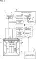
- Fig. 3 is a configuration diagram illustrating a configuration of the sound content generation device 40 that generates the sound content 30 used in the sound system 13 according to Embodiment 1.
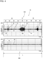
- Fig. 4 is an explanatory view for explaining a configuration of the sound content 30 used in the sound system 13 according to Embodiment 1.
- the horizontal axis represents time and the vertical axis represents a sound pressure level.
- the sound content 30 is, for example, generated by the sound content generation device 40.
- the sound content 30 includes the natural environmental sound 30A and the chord serial sound 30B.
- the natural environmental sound 30A is a sound that represents an environmental sound generated in nature.
- the chord serial sound 30B is a combination of chords that include a consonance and a dissonance.
- the sound content 30 is formed by mixing down the natural environmental sound 30A and the chord serial sound 30B. That is, the sound content 30 is obtained by adding the chord serial sound 30B to the natural environmental sound 30A.
- the natural environmental sound 30A and the chord serial sound 30B are concurrently emitted into the car 5 from the speaker system 22.
- the example illustrated in Fig. 4 is an example illustrating temporal changes of the natural environmental sound 30A and the chord serial sound 30B and an example of time waveforms of the natural environmental sound 30A and the chord serial sound 30B before mixing-down.
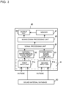
- the sound content generation device 40 includes an input unit 41, a natural environmental sound generation unit 42, a chord serial sound generation unit 43, a signal processing unit 44, a mixing-down processing unit 45, an output unit 46, and a memory 47.
- the input unit 41 has a first input unit 41a and a second input unit 41b.
- the first input unit 41a receives material data of a natural environmental sound that expresses a sound generated in nature from a recorder (not illustrated), a memory (not illustrated), or a sound material database 60 that is externally provided.
- the material data of the natural environmental sound may be either recorded sound data obtained by recording a sound that is actually generated in nature or pseudo data that is artificially generated and sounds like a sound in nature.
- the second input unit 41b receives sound data of a consonance and a dissonance from a musical instrument (not illustrated) or the sound material database 60 that is externally provided.
- the sound material database 60 is a database in which various kinds of sound materials such as the recorded sound data obtained by recording a sound that is actually generated in nature, the pseudo data that is artificially generated and sounds like a sound in nature, sound effects, chords, and human voice are stored.
- the natural environmental sound generation unit 42 generates the natural environmental sound 30A by use of the material data of the natural environmental sound input to the first input unit 41a.
- the natural environmental sound 30A includes a natural background sound (hereinafter referred to as a natural BG sound) 31 and an additional sound 32 added to the natural BG sound 31.
- the natural BG sound 31 is a sound generated by an environmental state in nature.
- the natural BG sound 31 includes at least one of a sound of trees shaking in the wind, a sound of water flowing in a river or sea, a sound of a crowd, and a sound of movement of an artificial object such as a car and a train.
- the additional sound 32 is a sound generated by behavior of a living organism in nature.
- the additional sound 32 includes at least one of chirping of one or more birds, a sound of wings of one or more flying birds, a flying sound at takeoff of one or more birds, a sound of chirping of one or more insects, a cry of one or more animals, and human voice.
- the natural environmental sound generation unit 42 adds the additional sound 32 to the natural BG sound 31 on the basis of a preset timing adjustment rule.
- the timing adjustment rule is stored in the memory 47. Note that two or more kinds of timing adjustment rules may be stored in the memory 47. In this case, a timing adjustment rule to be used is selected from among the two or more kinds of timing adjustment rules by a user.
- a timing of addition of the additional sound 32 to the natural BG sound 31 may be input by a user who operates the sound content generation device 40 without using the timing adjustment rule in the memory 47.
- the natural BG sound 31 is set such that the natural BG sound 31 is to be continuously emitted over a whole time length L of the natural environmental sound 30A.
- the whole time length L of the natural environmental sound 30A is 2 minutes or less.
- the additional sound 32 is individually set in each time section 35 obtained by dividing the time length L. Each time section 35 thus has a time length set in accordance with the timing adjustment rule.
- a sound pressure level of the additional sound 32 is higher than a sound pressure level of the natural BG sound 31.
- the sound pressure level of the additional sound 32 is set higher than the sound pressure level of the natural BG sound 31 on the basis of a preset sound pressure adjustment rule.
- the sound pressure adjustment rule is stored in the memory 47. Two or more kinds of sound pressure adjustment rules may be stored in the memory 47. In this case, a sound pressure adjustment rule to be used is selected from among the two or more kinds of sound pressure adjustment rules by a user. Alternatively, sound pressure levels of the natural BG sound 31 and the additional sound 32 may be input by a user who operates the sound content generation device 40 without using the sound pressure adjustment rule in the memory 47.
- the chord serial sound generation unit 43 generates the chord serial sound 30B by use of sound data of a consonance and a dissonance input to the second input unit 41b.
- the chord serial sound 30B is a combination of a consonance 33 and a dissonance 34.
- Fig. 5 is an explanatory view for explaining a configuration of the chord serial sound 30B included in the sound content 30 used in the sound system 13 according to Embodiment 1.
- the chord serial sound 30B is generated by the chord serial sound generation unit 43 provided in the sound content generation device 40. As illustrated in Fig.
- the chord serial sound 30B is constituted such that the consonance 33 and the dissonance 34 are alternately arranged, for example, in an order of consonance 33 ⁇ dissonance 34 ⁇ consonance 33.
- a time length L1 of the consonance 33 is identical to a time length L2 of the dissonance 34 or is longer than the time length L2.
- the following describes an example of time allocation of the time length L1 of the consonance 33 and the time length L2 of the dissonance 34.
- the time allocation can be decided in any ways as appropriate without being limited to the following examples.
- the consonance 33 and the dissonance 34 are alternately arranged on the basis of a preset time allocation rule.
- the time allocation rule is stored in the memory 47.
- the memory 47 stores, in the memory 47, two or more kinds of time allocation rules.
- the user selects a time allocation rule to be used from among these time allocation rules.
- the whole time length L of the chord serial sound 30B is 2 minutes or less. Since the chord serial sound 30B is repeatedly reproduced, a chord at an end of the chord serial sound 30B is set to the dissonance 34 in a case where a chord at a beginning of the chord serial sound 30B is the consonance 33, as illustrated in the example of Fig. 5 .
- chord at the beginning of the chord serial sound 30B is the dissonance 34
- the chord at the end of the chord serial sound 30B is set to the consonance 33.
- the consonances 33 or the dissonances 34 are arranged successively even at the joint part.
- the signal processing unit 44 performs one or more kinds of signal processing on the natural environmental sound 30A generated by the natural environmental sound generation unit 42 and the chord serial sound 30B generated by the chord serial sound generation unit 43 as needed.
- a timing of the signal processing may be before mixing-down processing performed by the mixing-down processing unit 45 or may be after the mixing-down processing.
- the signal processing unit 44 may perform the signal processing on only one of the natural environmental sound 30A and the chord serial sound 30B.
- Examples of the signal processing include a plurality of kinds of processing such as generation of an introduction part 36 and others, which will be described later, adjustment of a sound pressure level, and phase control processing. The signal processing will be described later.
- the mixing-down processing unit 45 generates the sound content 30 by mixing down the natural environmental sound 30A and the chord serial sound 30B.
- the mixing-down processing unit 45 mixes down the natural environmental sound 30A and the chord serial sound 30B on the basis of a preset synchronization timing adjustment rule.
- the synchronization timing adjustment rule is stored in the memory 47.
- the processing circuit is dedicated hardware or a processor.
- the dedicated hardware is, for example, an application specific integrated circuit (ASIC) or a field programmable gate array (FPGA).
- the processor executes a program stored in a memory.
- the memory 9d is a memory.
- the memory is a non-volatile or volatile semiconductor memory such as a random access memory (RAM), a read only memory (ROM), a flash memory, and an erasable programmable ROM (EPROM) or a disc such as a magnetic disc, a flexible disc, and an optical disc.
- a hardware configuration of the sound-field control device 21 is described. Functions of the sound-field control unit 21a, the output unit 21b, and the timer unit 21d of the sound-field control device 21 are implemented by a processing circuit.
- the processing circuit is dedicated hardware or a processor.
- the dedicated hardware and processor may be identical to those described above, and therefore description of the dedicated hardware and processor is omitted.
- the memory 21c is a memory. The memory may be identical to that described above, and therefore description of the memory is omitted.
- a hardware configuration of the sound content generation device 40 is described. Functions of the input unit 41, the natural environmental sound generation unit 42, the chord serial sound generation unit 43, the signal processing unit 44, the mixing-down processing unit 45, and the output unit 46 of the sound content generation device 40 are implemented by a processing circuit.
- the processing circuit is dedicated hardware or a processor.
- the dedicated hardware and processor may be identical to those described above, and therefore description of the dedicated hardware and processor is omitted.
- the memory 47 is a memory. The memory may be identical to that described above, and therefore description of the memory is omitted.
- software configurations of the sound material database 60 and the sound content generation device 40 may be, for example, virtual singer software that is application of a singing voice synthesizing technique such as vocaloid (registered trademark).
- Fig. 6 is a front view illustrating a configuration of the sound system 13 according to Embodiment 1.
- Fig. 7 is a plan view illustrating a layout of the speaker cabinets 20 of the sound system 13 according to Embodiment 1.
- Fig. 7 illustrates a state where the suspended ceiling 10 of the car 5 is looked up at from the floor board 5b of the car 5.
- a height direction of the car 5 is a Y direction
- a width direction of the car 5 is an X direction
- a depth direction of the car 5 is a Z direction.
- the Y direction is, for example, a vertical direction.
- the X direction is a left-right direction of the car 5
- the Z direction is a front-back direction of the car 5, as illustrated in Fig. 7 .
- the sound system 13 includes the speaker system 22 provided to a ceiling of the enclosed space and the sound-field control device 21.
- the speaker system 22 includes one or more speaker cabinets 20.
- Each speaker cabinet 20 includes one or more speaker units 23.
- the sound system 13 forms a sound field 27 and emits a sound to a user of the car 5.
- the sound content 30 obtained by mixing down the natural environmental sound 30A that is generated in nature such as a murmur of a stream or chirping of a bird and the chord serial sound 30B obtained by combining the consonance 33 and the dissonance 34 is used as the sound.
- Embodiment 1 a sound-field environment of two or more channels is created in the enclosed space, and the sound content 30 is reproduced in this sound-field environment.
- the sound content 30 can be emitted to the enclosed space from plural directions, and a "comfortable feeling" can be given to an auditory sense of a user in the enclosed space.
- an unpleasant element such as stress during stay in a narrow space can be reduced.
- the natural environmental sound 30A that is a main part of the sound content 30 is constituted such that a user can feel, from the sound, a season such as spring, summer, autumn, and winter, which, for example, anyone who lives in Japan can feel, and a living time zone such as dawn, daytime, evening, and night. This allows the user to perceive a sense of a time zone and a sense of a season from the "sound" even in an enclosed space where an external environment cannot be seen. Furthermore, the natural environmental sound 30A has a content configuration without noisiness or other state excluding an unpleasant factor such as noise and is thus formed not to give an auditory unpleasant feeling. Specifically, the natural environmental sound 30A is a combination of a sound source type such as a flow of wind and a river or chirping of a bird in nature, a time zone, and a frequency band.
- a sound source type such as a flow of wind and a river or chirping of a bird in nature, a time zone, and a frequency band.
- the speaker system 22 includes two speaker cabinets 20, as illustrated in Fig. 6 .
- the number of speaker cabinets 20 is not limited to two and may be any number of two or more. This can form the sound field 27 of two or more channels in the enclosed space.
- Each speaker cabinet 20 is provided in the internal space of the suspended ceiling 10, as illustrated in Fig. 6 .
- a position of each speaker cabinet 20 is not limited to an inside of the suspended ceiling 10, and each speaker cabinet 20 may be provided to at least one of the ceiling board 5c of the car 5, the side board 5a of the car 5, and the floor board 5b of the car 5.
- Each speaker cabinet 20 includes the speaker unit 23 and a housing 25. Note that although the speaker system 22 includes the speaker cabinets 20 in Embodiment 1, this case is not restrictive.
- the speaker system 22 may include only one or more speaker units 23 without including the speaker cabinets 20.
- the speaker unit 23 and the speaker cabinet 20 are disposed in the suspended ceiling 10 in Embodiment 1, this case is not restrictive. That is, the speaker unit 23 and the speaker cabinet 20 may be disposed at another position such as the side board 5a of the car 5.
- the number of speaker cabinets 20 provided in the car 5 is any number of two or more in the above description, this case is not restrictive. That is, the number of speaker cabinets 20 provided in the car 5 and the number of speaker units 23 may be any number of one or more, and these numbers may be decided as appropriate depending on a capacity, an intended purpose, and other features of the car 5.
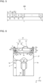
- Fig. 8 is a side view illustrating an example of a configuration of the speaker cabinet 20 according to Embodiment 1.
- Fig. 9 is a front view illustrating the configuration of the speaker cabinet 20 of Fig. 8 .
- the speaker cabinet 20 includes the speaker unit 23 and the housing 25.
- the speaker unit 23 is housed in the housing 25.
- the speaker unit 23 is provided on a front surface 25a of the housing 25 and has an emission surface 23a that emits a sound toward an outside.
- the housing 25 has, for example, a cuboid shape.
- the housing 25 is a hollow sealed device.
- the emission surface 23a of the speaker unit 23 is fitted into an installation hole provided in the front surface 25a of the housing 25 and is exposed to an outside through the installation hole.
- All other parts of the speaker unit 23 are provided in the housing 25. A sound from the emission surface 23a of the speaker unit 23 is thus emitted only in a direction indicated by arrow A in Fig. 8 and is not emitted to an outside through parts of the housing 25 other than the emission surface 23a.
- Fig. 10 is a side view illustrating a configuration of a modification of the speaker cabinet 20 according to Embodiment 1.
- Fig. 11 is a front view illustrating the configuration of the speaker cabinet 20 of Fig. 10 .
- the speaker cabinet 20 may have two or more speaker units 23 housed in the housing 25.
- one speaker unit 23-1 may be a full-range speaker
- the other speaker unit 23-2 may be a tweeter.
- the full-range speaker reproduces a range from a low range to a high range by itself.
- the speaker unit 23 in a case where the single speaker unit 23 is housed in the housing 25 of the speaker cabinet 20, the speaker unit 23 is a full-range speaker.
- the tweeter is a speaker exclusive for a low range used to assist the full-range speaker. It is difficult to reproduce a range from a low range to a high range by a single speaker, and sound quality may become insufficient. In such a case, the tweeter is used to supplement the insufficiency.
- the two or more speaker units 23 disposed in the housing 25 may be different kinds of speaker units as described above or may be speaker units of an identical kind. It is, however, desirable that one speaker is a full-range speaker and the other speaker is a speaker exclusive for a low range or exclusive for a high range used to assist the full-range speaker. In this case, it is possible to cope with a wide frequency band from a low range to a high range and to perform sound emission for each narrow frequency band.
- one speaker cabinet 20 includes a plurality of speaker units 23, an improvement in sound quality and enlargement of a reproduction band can be achieved by the speaker cabinet 20 alone. As a result, it is possible to easily obtain a "high-sound-quality system" that can cover a wide frequency band.
- the speaker cabinets 20 are disposed in the internal space of the suspended ceiling 10.
- a height of the suspended ceiling 10 in the Y direction (a height direction of the car 5) is, for example, approximately 5 cm.
- a height H1 of the housing 25 of the speaker cabinet 20 in the Y direction (the height direction of the car 5) is thus less than or equal to 5 cm.
- the height H1 is in a range of 3 cm to 20 cm. Therefore, the height H1 of the housing 25 is limited by the height of the suspended ceiling 10 in the Y direction (the height direction of the car 5).
- the emission surface 23a of the speaker unit 23 is disposed and faces the side board 5a of the car 5, as illustrated in Figs. 6 and 7 .
- the emission surface 23a is disposed along an edge of the side surface 10a of the suspended ceiling 10.
- the emission surface 23a is located within a same plane as the side surface 10a of the suspended ceiling 10.
- a position of the emission surface 23a in the X direction thus matches or almost matches a position of the side surface 10a of the suspended ceiling 10 in the X direction.
- the side surface 10a of the suspended ceiling 10 has an opening at a position corresponding to the position of the emission surface 23a. Note that the whole side surface 10a of the suspended ceiling 10 may be opened.
- a sound emitted from the emission surface 23a is thus not blocked by the side surface 10a of the suspended ceiling 10. Furthermore, as described above, the gap 11 of the first distance D is present between the side surface 10a of the suspended ceiling 10 and the side board 5a of the car 5.
- the first distance D is approximately 5 cm. Note that the first distance D is set as appropriate within a range of 2 cm to 20 cm, desirably within a range of 3 cm to 10 cm in accordance with the specifications of the car 5 of the elevator 1.
- a sound emitted from the emission surface 23a of the speaker unit 23 is emitted in the direction indicated by arrow A. Then, the sound is reflected by the side board 5a of the car 5 and becomes a reflected sound.
- the reflected sound travels in a direction indicated by arrow B, as illustrated in Figs. 6 and 7 .
- the speaker unit 23 performs "indirect sound emission" of emitting a sound to a user by utilizing reflection of the side board 5a of the car 5.
- the emission surface 23a of the speaker unit 23 is disposed in proximity with the side board 5a of the car 5 and faces the side board 5a of the car 5 with the gap 11 having the first distance D interposed between the emission surface 23a and the car 5.
- the first distance D is, for example, approximately 5 cm, as described above. Therefore, a sound emitted from the emission surface 23a of the speaker unit 23 is reflected by the side board 5a of the car 5 immediately after the emission before a sound pressure level decreases.
- the speaker cabinet 20 is disposed further rearward than a central part of the suspended ceiling 10 in the Z direction (a depth direction of the car 5). Note that a position of the speaker cabinet 20 in the Z direction is not limited to this position, and the speaker cabinet 20 may be provided in a central part of the suspended ceiling 10 in the Z direction or may be provided further forward than the central part of the suspended ceiling 10 in the Z direction. Furthermore, as illustrated in Fig. 6 , the speaker cabinet 20 is disposed in a central portion of the suspended ceiling 10 in the Y direction (the height direction of the car 5). Note that the position of the speaker cabinet 20 in the Y direction is not limited to this position, and may be a position above the central portion of the suspended ceiling 10 in the Y direction or may be a position below the central portion.
- the speaker unit 23 provided in one of the two speaker cabinets 20 illustrated in Fig. 7 is referred to as a speaker unit 23R. Furthermore, the speaker unit 23 provided in the speaker cabinet 20 is referred to as a speaker unit 23L.
- the speaker unit 23R and the speaker unit 23L are disposed apart from each other. Note that the speaker cabinet 20 that houses the speaker unit 23R and the speaker cabinet 20 that houses the speaker unit 23L are disposed apart from each other by a certain distance centered on a central portion of the suspended ceiling 10 in the X direction. The certain distance is referred to as a second distance D2.
- the second distance D2 is determined by a dimension of the car 5 in the X direction, the first distance D, and a dimension of the housing 25 in the X direction.
- the speaker unit 23R and the speaker unit 23L are disposed such that back surfaces of the speaker unit 23R and the speaker unit 23L face each other. As illustrated in Fig. 7 , the emission surface 23a of the speaker unit 23R is thus disposed and faces the side board 5a of the car 5 on the right side. On the other hand, the emission surface 23a of the speaker unit 23L is disposed and faces the side board 5a of the car 5 on the left side. Each of the emission surfaces 23a of the speaker units 23R and 23L is disposed and faces the gap 11. Each of the emission surfaces 23a of the speaker units 23R and 23L is disposed within a same plane as the side surface 10a of the suspended ceiling 10 on the corresponding one of the left side and the right side.
- a user stands and faces the car door 5d in the car 5 of the elevator 1. Therefore, a sound emitted from the speaker unit 23R mainly reaches the right ear of the user, and a sound emitted from the speaker unit 23L mainly reaches the left ear of the user.
- the sound emitted from the speaker unit 23R is referred to as a "right-side sound”
- the sound emitted from the speaker unit 23L is referred to as a "left-side sound”.
- FIG. 12 is a front view schematically illustrating a configuration of a modification of the sound system 13 according to Embodiment 1.
- Fig. 12 two speaker units 23R-1 and 23L-1 are provided and face the floor board 5b of the car 5. Emission surfaces 23a of the speaker units 23R-1 and 23L-1 are thus disposed and face the floor board 5b of the car 5, as illustrated in Fig. 12 .
- the speaker cabinet 20 that houses the speaker unit 23R-1 and the speaker cabinet 20 that houses the speaker unit 23L-1 are disposed apart from each other by a certain distance centered on the central portion of the suspended ceiling 10 in the X direction.
- the certain distance is referred to as a third distance D3.
- the third distance D3 may be identical to the second distance D2 illustrated in Fig. 7 or may be different from the second distance D2.
- each of the emission surfaces 23a of the speaker units 23R-1 and 23L-1 is disposed within a same plane as the lower surface 10b of the suspended ceiling 10.
- a position of each emission surface 23a in the Y direction thus matches or almost matches a position of the lower surface 10b of the suspended ceiling 10 in the Y direction.
- portions of the emission surfaces 23a of the speaker units 23R-1 and 23L-1 are fitted into respective attachment holes provided in the lower surface 10b of the suspended ceiling 10.
- Each of the emission surfaces 23a of the speaker units 23R-1 and 23L-1 is exposed to an outside through the attachment hole. A sound emitted from each of the emission surfaces 23a of the speaker units 23R-1 and 23L-1 is thus not blocked by the lower surface 10b of the suspended ceiling 10.
- a sound emitted from the speaker units 23R-1 and 23L-1 is emitted in the direction indicated by arrow A from the emission surface 23a.
- the speaker units 23R-1 and 23L-1 perform "direct sound emission" of directly emitting a sound to a user from the suspended ceiling 10.
- Fig. 13 is a plan view schematically illustrating a configuration of another modification of the sound system 13 according to Embodiment 1.
- Fig. 13 illustrates a state where the lower surface 10b of the suspended ceiling 10 is viewed from the floor board 5b.
- four speaker units 23R-1, 23R-2, 23L-1, and 23L-2 are provided.
- two speaker units 23R-2 and 23L-2 among the four speaker units 23R-1, 23R-2, 23L-1, and 23L-2 are provided and face the side board 5a of the car 5 on the front side.
- the other two speaker units 23R-1 and 23L-1 are provided and face the floor board 5b of the car 5.
- the emission surfaces 23a of the speaker units 23R-1 and 23L-1 are thus disposed and face the floor board 5b of the car 5, as illustrated in Fig. 12 .
- the two speaker units 23R-2 and 23L-2 on the front side are provided and face the side board 5a of the car 5 on the front side.
- the speaker cabinet 20 that houses the speaker unit 23R-2 and the speaker cabinet 20 that houses the speaker unit 23L-2 are disposed apart from each other by a certain distance centered on the central portion of the suspended ceiling 10 in the X direction.
- the certain distance may be, for example, identical to the third distance D3 illustrated in Fig. 12 or may be, for example, different from the third distance D3.
- the gap 11 of the first distance D is present between the side board of the suspended ceiling 10 and the side board 5a of the car 5.
- a sound emitted from the speaker units 23R-2 and 23L-2 is emitted in a direction indicated by arrow A from the emission surface 23a.
- the sound is reflected by the side board 5a of the car 5 and becomes a reflected sound.
- the reflected sound travels in a direction indicated by arrow B, as illustrated in Fig. 13 .
- the speaker units 23R-2 and 23L-2 perform "indirect sound emission" of emitting a sound to a user from the suspended ceiling 10 by utilizing reflection of the side board 5a of the car 5.
- the two speaker units 23R-1 and 23L-1 on the back side are provided and face the floor board 5b of the car 5, as described above with reference to Fig. 12 . Accordingly, as described above, the two speaker units 23R-1 and 23L-1 on the back side perform "direct sound emission” of directly emitting a sound to a user from the suspended ceiling 10.
- "indirect sound emission” and “direct sound emission” may be combined, as in the modification of Fig. 13 .
- the speaker units 23R and 23L illustrated in Fig. 7 may be provided instead of the speaker units 23R-2 and 23L-2.
- the speaker unit 23 may be provided at any place on the lower surface 10b of the suspended ceiling 10 in the car 5. Examples of a pattern in which the speaker unit 23 is provided include a case where the speaker units 23 are located on respective right and left sides as illustrated in Fig. 7 , a case where the speaker units 23 are provided on respective front and back sides, and a case where the speaker units 23 are provided at respective corners of the lower surface 10b of the suspended ceiling 10, and these cases can be combined freely. Note, however, that sound quality is good in a case where the speaker units 23 are apart from each other to some degree. Therefore, in Embodiment 1, the speaker cabinets 20 that each house the speaker unit 23 are disposed apart from each other by the second distance D2 or the third distance D3.
- the speaker cabinet 20 may be provided inside the floor board 5b of the car 5.
- the speaker cabinet 20 is basically provided at a position higher than the chest of a user to accomplish high-sound-quality reproduction. It is therefore desirable to provide the speaker cabinet 20 in the suspended ceiling 10 or on an upper portion of the side board 5a of the car 5.
- the sound field 27 generated by the sound system 13 is, for example, a range indicated by the broken line in Fig. 6 .
- a height H2 of a lower limit 27a of the sound field 27 is, for example, approximately 1.0 m to 1.8 m, desirably 1.6 m to 1.8 m from the floor board 5b of the car 5.
- a height of an upper limit of the sound field 27 is, for example, 1.8 m to 2.0 m from the floor board 5b of the car 5. It is therefore desirable to form the sound field 27 such that a height of the sound field 27 from the floor board 5b is in a range of 1.6 m to 1.8 m. Therefore, the sound field 27 is generated above the lower limit 27a in the car 5.
- the sound field 27 is formed around the head of a user, as illustrated in Fig. 6 .
- the height H2 of the lower limit 27a of the sound field 27 is set on the basis of an average body height of users (excluding junior-high-school kids and younger kids). Note that in a range of a height from the floor board 5b of 0 m to less than 1.6 m, a good sound field cannot be formed in a case where a plurality of users are in the car 5 since a sound is blocked or absorbed by the bodies of the users, as described above. Furthermore, in a range of the height from the floor board 5b exceeding 1.8 m, the sound field 27 is deviated above the heads of users, users' hearing becomes hard.
- the range where the sound field 27 is generated is not limited to the range of 1.6 m to 1.8 m. That is, the height H2 of the lower limit 27a of the sound field 27 is desirably, for example, in a range of 1.0 m to 1.8 m from the floor board 5b of the car 5 since it is only necessary that the sound field 27 is generated in a range higher than the chest of a user on the basis of an average body height of users (excluding junior-high-school kids and younger kids).
- the sound content 30 is sound data for reproducing a sound signal sent out from the speaker system 22 under control of the sound-field control unit 21a.
- the sound content 30 is obtained by mixing down the natural environmental sound 30A and the chord serial sound 30B obtained by combining the consonance 33 and the dissonance 34.
- the upper stage of Fig. 4 is an example of a time waveform of the natural environmental sound 30A
- the lower stage of Fig. 4 is an example of a time waveform of the chord serial sound 30B.
- (1) to (3) indicate the additional sound 32.
- (1) indicates a cry of one or more animals
- (2) indicates chirping of one or more birds
- (3) indicates a flying sound at takeoff of one or more birds and chirping of one or more birds.
- (4) indicates the natural BG sound 31.
- (4) includes at least one of a sound of trees shaking in the wind, a sound of water flowing in a river or sea, a sound of a crowd, human voice, and a sound of movement of an artificial object such as a car and a train.
- the natural BG sound 31 is set throughout the whole time length L of the sound content 30.
- the additional sound 32 is temporally spaced apart from another one.
- (5) indicates a state of fade-in of the sound content 30, and (6) indicates a state of fade-out of the sound content 30.
- fade-in means that a sound pressure level of sound content gradually increases
- fade-in processing means processing of gradually increasing a sound pressure level of sound content.
- fade-out means that a sound pressure level of sound content gradually decreases
- fade-out processing means processing of gradually decreasing a sound pressure level of sound content. That is, the fade-in processing is performed on a beginning part of the sound content 30, and the fade-out processing is performed on an end part of the sound content 30.
- a sound pressure level at a joint part 30a (see Fig. 14 ) where the beginning part of the sound content 30 and the end part of the sound content 30 are joined to each other is lowest.
- the chord serial sound 30B illustrated in the lower stage of Fig. 4 is constituted such that the consonance 33 and the dissonance 34 are alternately arranged with passage of time, as illustrated in Fig. 5 .
- the time length L1 of the consonance 33 is longer than or equal to the time length L2 of the dissonance 34.
- one of a chord at a beginning and a chord at an end of the chord serial sound 30B is the consonance 33, and the other one of the chords is the dissonance 34.
- the whole time length L of the sound content 30 (i.e., a sound signal) is set to 2 minutes or less. That is, the time length L of the sound content 30 is 2 minutes (i.e., 120 seconds) at maximum possible.
- an up-down movement time of the car 5 of the elevator 1 depends on a height of the building, the movement time of the car 5 is approximately 2 minutes or less in many cases even when the building is tall. The reason is as follows. A space in the car 5 is an enclosed space. When users are restrained for a long time in the enclosed space, the users cannot even move, and therefore a stressful condition continues. Furthermore, in the car 5, strangers are extremely close to each other in the enclosed space. It can be said that this is an undesirable state from the perspective of crime prevention.
- an actual travelling time of the car 5 of the elevator 1 is limited to 90 seconds or less, and even in a case of a super tall building, the actual travelling time of the car 5 is limited to 90 seconds or less to 120 seconds or less. Therefore, in Embodiment 1, the time length L of a single piece of sound content 30 is set to 2 minutes or less, that is, 90 seconds or less to 120 seconds or less. In the example of Fig. 4 , the time length L of the sound content 30 is set to 90 seconds. Furthermore, the sound content 30 set to 2 minutes to or less is repeatedly reproduced continuously in the car 5 under control of the sound-field control unit 21a. The sound content 30 thus repeatedly reproduced is generated and has a melody that changes on a constant cycle.
- the sound content 30 may be used under an environment other than an elevator.
- the time length L of the sound content 30 may be longer than 2 minutes.
- one of a chord at a beginning and a chord at an end of the chord serial sound 30B is the consonance 33, and the other one of the chords is the dissonance 34.
- the consonance 33 and the dissonance 34 are linked at the joint part 30a of the sound content 30 when the sound content 30 is reproduced in a loop.
- an abnormal sound sometimes occurs at the joint part 30a of the sound content 30.
- the abnormal sound is, for example, caused due to performance of an acoustic circuit or a data recording device in which the sound content 30 is stored, especially degradation of the data recording device in which the sound content 30 is stored. Since a user in the car 5 is in a quiet environment, the abnormal sound (pop noise) is remarkably easily heard by the user and is sometimes perceived as a very unpleasant abnormal sound. To prevent an unpleasant feeling caused by the abnormal sound (pop noise), the sound content 30 has the following configuration in Embodiment 1.
- Fig. 14 is an explanatory view schematically illustrating a temporal change of a sound pressure level of the sound content 30 used in the sound system 13 according to Embodiment 1.
- Fig. 14 schematically illustrates a sound pressure level of the whole sound content 30 combining a sound pressure level of the natural environmental sound 30A and a sound pressure level of the chord serial sound 30B of the sound content 30.
- the sound content 30 is reproduced in a loop on a cycle corresponding to the time length L.
- (5) indicates a fade-in state of the sound content 30
- (6) indicates a fade-out state of the sound content 30.
- fade-in processing of gradually increasing a sound pressure level is performed at a beginning part of the sound content 30 at which reproduction starts
- fade-in processing of gradually increasing a sound pressure level is performed at an end part of the sound content 30 at which reproduction ends. Therefore, in a case where the sound content 30 is reproduced in a loop, the (6) fade-out processing and the (5) fade-in processing are performed at the joint part 30a of the sound content 30, as illustrated in Fig. 14 .
- a time length L3 of the joint part 30a is set to 3 seconds or less.
- the sound pressure level of the sound content 30 is decreased by 6 dB as compared with the original sound pressure level.
- the sound pressure level of the sound content 30 decreased by the fade-out processing is increased by 6 dB to become the original sound pressure level. Note that an amount of the increase or decrease of the sound pressure level is not limited to 6 dB and may be 6 dB ⁇ ⁇ ( ⁇ is any value).
- the fade-out processing at the joint part 30a such that the sound pressure level of the sound content 30 is decreased by 6 dB as compared with the original sound pressure level, it is possible to prevent an abnormal sound (pop noise) that occurs at the joint part 30a from being remarkably heard. Furthermore, in a quiet space of a general silent elevator, many users have an uncomfortable feeling and an unpleasant feeling. In Embodiment 1, the fade-out processing and the fade-in processing of the joint part 30a are performed within 3 seconds in total, and therefore only instantaneous silence occurs. It is therefore possible to prevent a user from having an unpleasant feeling, which a user has in a quite space of a general elevator.
- the car 5 stops at a floor designated by a user in response to a user's operation of a button while the car 5 is moving up and down. During that time, the sound content 30 is repeatedly reproduced. Therefore, a user cannot always hear the sound content 30 from the beginning part. Some users of the elevator 1 may hear the sound content 30 in the middle of reproduction. Furthermore, some users may use the elevator 1 to move one floor (e.g., from the fourth floor to the fifth floor) although many users use the elevator 1 to move plural floors (e.g., from the first floor to the tenth floor).
- the "chord serial sound 30B” is merely a collection of a series of chords in which the consonance 33 and the dissonance 34 are arranged, unlike general music. Therefore, the "chord serial sound 30B” is also a “sound having no meaning”. In a case where a "sound having no meaning” is reproduced, even in a case where a user is forced to stop listening to the sound in the middle of reproduction of the sound, a possibility of giving stress to the user is extremely low.
- a sound pressure level of the chord serial sound 30B is lower by 3 dB to 6 dB in average than a sound pressure level of the natural environmental sound 30A. Accordingly, the natural environmental sound 30A becomes a main sound of the sound content 30, and the chord serial sound 30B becomes a background sound (back sound) of the natural environmental sound 30A.
- the natural environmental sound 30A is obtained by adding the additional sound 32 such as chirping of a bird to the natural BG sound 31 such as a murmur of a stream, as described above. Therefore, the natural environmental sound 30A fluctuates in sound pressure level and tends to be intermittent.
- the chord serial sound 30B has a musical pitch and tone configuration of a constant cycle. Therefore, even in a case where the sound pressure level of the natural environmental sound 30A temporarily becomes low, the chord serial sound 30B is presented to a user with an almost identical sound pressure level.
- chord serial sound 30B is a collection of a series of chords in which the consonance 33 and the dissonance 34 are arranged.
- the consonance 33 and the dissonance 34 are described below.
- Fig. 15 is a basic explanatory view of the consonance 33 and the dissonance 34 used in the sound system 13 according to Embodiment 1. As illustrated in Fig. 15 , the consonance 33 and the dissonance 34 that form the chord serial sound 30B are each a chord constituted by sounds within 1 octave.
- Fig. 15 As illustrated in Fig. 15 , as a basic of a chord, how much two notes are apart from each other is expressed in stages by use of ordinal numbers.
- the two notes are referred to as a "lower note” and a “higher note”.
- each "higher note” is expressed by use of an ordinal number in a case where the "lower note” is low “do”.
- a note of the same pitch is called "perfect first" or "unison”
- an interval of one semitone is called “minor second”
- an interval of two semitones is called “major second”.
- an interval of three semitones is called “minor third”
- an interval of four semitones is called “major third”.
- Fig. 16 is an explanatory view illustrating a relationship between the "lower note” and the "higher note” that constitutes a chord used in the sound system 13 according to Embodiment 1 in the form of a list by use of ordinal numbers.
- consonance 33 is a chord in the consonant state where the two or more notes that occur simultaneously are harmonious.
- dissonance 34 is a chord in the dissonant state where the two or more notes that occur simultaneously are unharmonious.
- Fig. 17 illustrates an example of definition of the consonance 33 and the dissonance 34 used in the sound system 13 according to Embodiment 1.
- the consonance 33 includes, for example, perfect first, perfect eighth, perfect fifth, perfect fourth, major third, minor third, major sixth, and minor sixth.
- the dissonance 34 includes, for example, major second, minor second, major seventh, minor seventh, and others.
- Figs. 18 and 19 illustrate examples of the consonance 33 used in the sound system 13 according to Embodiment 1.
- Fig. 20 illustrates an example of the dissonance 34 used in the sound system 13 according to Embodiment 1.
- the consonance 33 and the dissonance 34 to be used are selected as appropriate from among these consonances 33 and dissonances 34. By alternately arranging the selected consonance 33 and dissonance 34, the chord serial sound 30B is generated.
- the dissonance 34 has a ratio of the numbers of oscillations (frequency) that is not an integer ratio, unlike the consonance 33. That is, in the dissonance 34, one note has a frequency component that is not an integer multiple of a frequency of the other note. Therefore, the dissonance 34 can presents a tone change. In the chord serial sound 30B, the consonance 33 and the dissonance 34 are alternately reproduced. Therefore, a user alternately hears a tone of a constant cycle produced by the consonance 33 and a tone causing a periodic change produced by the dissonance 34 and therefore feels an auditory change.
- the cocktail-party effect is brain activity of unconsciously hearing out only information related to oneself or information interesting to an individual from among ambient sounds.
- a human brain has sorting capability of naturally distinguishing voice of a conversation partner even though an ambient noise level is quite high in a gathering where a large number of people are conversing such as a cocktail party. This sorting capability is the cocktail-party effect.
- chord serial sound 30B in which the dissonance 34 is inserted between the consonances 33, allows a user to feel an auditory change.
- the user once the user becomes aware of the chord serial sound 30B, user's attention is focused on the chord serial sound 30B due to the cocktail-party effect. Therefore, the user subconsciously listens to the chord serial sound 30B. This lessens a user's sense of being in an enclosed space of the car 5 of the elevator. As a result, user's uncomfortable feeling and unpleasant feeling are reduced.
- a dissonance produces “tension” that makes a person uneasy or excited, and a consonance produces “relaxation” that makes a person peaceful or calm.
- a person feels bored, and the cocktail-party effect does not occur. Therefore, in the chord serial sound 30B according to Embodiment 1, "tension” of the dissonance 34 is inserted between “relaxation” of the consonances 33. That is, the chord serial sound 30B is repetition of "relaxation” and "tension”.
- “relaxation” occurs after “tension” that sometimes occurs, a user is freed from “tension” and feels comfortable. As a result, the user can feel expanse of sound and can have a sense of openness, a refreshing feeling, and a comfortable feeling.
- Fig. 21 is an explanatory view illustrating an example of characteristics of a frequency band used as the chord serial sound 30B used in the sound system 13 according to Embodiment 1.
- the horizontal axis represents a frequency
- the vertical axis represents a sound pressure level.
- the thick line 50 represents a main band of the chord serial sound 30B
- the thin line 51 represents a sub band of the chord serial sound 30B.
- the main band of the chord serial sound 30B is a frequency band higher than or equal to approximately 100 Hz and less than 800 Hz.
- a frequency of the chord serial sound 30B is thus basically the range of the main band.
- the chord serial sound 30B is constituted by sounds within 1 octave as described above so that the frequency does not markedly change. The reason is described below. Human auditory characteristics have a high hearing sensitivity to a frequency band higher than approximately 1 kHz. Therefore, when the frequency of the chord serial sound 30B is markedly changed from a low frequency band to a high frequency band, only a sound of a high frequency is heard by a user, and for example, a phenomenon that the natural environmental sound 30A becomes hard to hear occurs.
- the chord serial sound 30B thus basically uses the main band so that the frequency does not markedly change. As a result, harmony between the natural environmental sound 30A and the chord serial sound 30B is kept.
- the chord serial sound 30B may partially use a sub band of a frequency band of 800 Hz to 2 kHz. Note that in a case where the sub band is used in the chord serial sound 30B, a time length of the sound is set to a short time shorter than or equal to 2 seconds so that an auditory function produced by a melody as a musical sound remains although the auditory cocktail-party effect is less likely to occur.
- the natural environmental sound 30A is formed by adding the additional sound 32 such as chirping of a bird to the natural BG sound 31 such as a murmur of a stream.
- the natural environmental sound 30A is an environmental sound combining sounds from a plurality of sound sources existing in nature. Note that a sound source of an environmental sound may be an artificially created sound source.
- a sound source configuration is, for example, as follows:
- the sound sources (1) to (3) are sound sources that constitute the natural BG sound 31 of Fig. 4 and are sounds that call up, in a user, an image of an environmental state in nature.
- Each of the sound sources (1) to (3) is a sound source (hereinafter referred to as a first sound source) by use of an environment in nature.
- a sound of each of the sound sources (1) to (3) is a sound generated from the first sound source, that is, a sound based on an environmental state in nature.
- a sound of the sound source (4) is a sound that constitutes the additional sound 32 of Fig. 4 and is a sound that calls up, in a user, an image of behavior of a living organism in nature.
- the sound source (4) is a sound source (hereinafter referred to as a second sound source) by use of, for example, a living organism living in nature.
- a sound of the sound source (4) is a sound generated from the second sound source, that is, a sound based on behavior of a living organism in nature.
- time sections 35 that constitute the natural environmental sound 30A have an identical time length, and the time sections 35 are set to at least two kinds of time lengths. That is, the time sections 35 may be set to two kinds of time lengths such as 2 seconds, 3 seconds, 5 seconds, and 8 seconds.
- the natural BG sound 31 is set such that the natural BG sound 31 is to be continuously emitted throughout all of the plurality of time sections 35.
- the additional sound 32 is individually set for each of the time sections 35 and is emitted for each of the time sections 35.
- a sound pressure level of the additional sound 32 is higher than a sound pressure level of the natural BG sound 31.
- a difference between the sound pressure level of the additional sound 32 and the sound pressure level of the natural BG sound 31 is 10 dB or more. When the difference in sound pressure level is too large, a user has an unpleasant feeling, and therefore an upper limit is set to approximately 20 dB.
- the sound pressure level of the additional sound 32 is made higher by a range of +10 dB to +20 dB (instantaneous) than the sound pressure level of the natural BG sound 31.
- the additional sound 32 is presented as a signal having a clearer sound pressure level than the natural BG sound 31.
- not all of the time sections 35 have the additional sound 32, and there is a time section 35 for which the additional sound 32 is not set.
- a time section 35 (hereinafter referred to as a "first time section") "with additional sound” to which the additional sound 32 is added and a time section 35 (hereinafter referred to as a "second time section”) "without additional sound” to which the additional sound 32 is not added are set. This is because there is a high possibility of giving a "noisy" impression to a user when the additional sound 32 is set in all of the time sections 35.
- the time sections 35 are arranged such that at least one of adjacent time sections 35 becomes the second time section "without additional sound” to give a "pleasant" impression to a user. That is, at least one second time section “without additional sound” is disposed between adjacent first time sections "with additional sound”. On the other hand, two or more second time sections "without additional sound” may be successively disposed.
- the natural environmental sound 30A has an introduction part 36 that includes one or more time sections 35, an ending part 38 that includes one or more time sections 35, and an intermediate part 37 that is set between the introduction part 36 and the ending part 38 and includes one time section 35.
- the introduction part 36 includes four time sections 35
- the intermediate part 37 includes one time section 35
- the ending part 38 includes four time sections 35.
- the number of time sections 35 described above is merely an example, and the number of time sections 35 is not limited to this example.
- the intermediate part 37 may include two or more time sections 35.
- the time section 35 that constitutes the intermediate part 37 may have a longest time length among the plurality of time sections 35. Specifically, in a case where time lengths of the other time sections 35 are 2 seconds to 8 seconds, the time section 35 that constitutes the intermediate part 37 may have a time length of approximately 15 seconds.
- a time length of a time section 35 having a maximum possible time length is referred to as a first time length.
- a time length of a time section 35 having a maximum possible time length is referred to as a second time length.
- the third time length may be set longer than each of the first time length and the second time length.
- the natural environmental sound 30A uses a sound in nature. Furthermore, a series of presented sounds of the natural environmental sound 30A gradually varies in sound intensity with passage of time in a way such as the introduction part 36 ⁇ the intermediate part 37 ⁇ the ending part 38, as in the case of general music. Specifically, in the natural environmental sound 30A, it is desirable to set a sound pressure level of the additional sound 32 highest and set a time length of the additional sound 32 longest in the intermediate part 37.
- a maximum possible value of the sound pressure level of the additional sound 32 in the time section 35 included in the introduction part 36 is referred to as a first level.
- a maximum possible value of the sound pressure level of the additional sound 32 in the time section 35 included in the ending part 38 is referred to as a second level.
- a maximum possible value of the sound pressure level of the additional sound 32 in the time section 35 included in the intermediate part 37 is referred to as a third level.
- the third level is set higher than the first level and the second level, as illustrated in Fig. 4 .
- the third level is set approximately 1.5 times to 4 times higher than each of the first level and the second level.
- a user hears the additional sound 32 of a high sound pressure level in the intermediate part 37 after hearing the additional sound 32 of a low sound pressure level in the introduction part 36.
- the user receives a change in sound intensity of the additional sound 32 with passage of time and does not hear a sudden change in sound.
- the user can hear a reproduced sound of the sound content 30 without a feeling of strangeness.
- the maximum possible value of the sound pressure level of the additional sound 32 in the time section 35 included in the intermediate part 37 is set as the third level in the above description, an average value of the sound pressure level of the additional sound 32 in the time section 35 included in the intermediate part 37 may be set as the third level.
- Fig. 22 illustrates instantaneous frequency characteristics obtained by performing fast Fourier transform (FFT) processing on a time waveform at a position of the point (B) in Fig. 4 . That is, Fig. 22 illustrates instantaneous frequency characteristics of the additional sound 32.
- Fig. 23 illustrates instantaneous frequency characteristics obtained by performing FFT processing on a time waveform at a position of the point (A) in Fig. 4 . That is, Fig. 23 illustrates instantaneous frequency characteristics of the natural BG sound 31.
- the horizontal axis represents a frequency
- the vertical axis represents a sound pressure level.
- Figs. 22 and 23 are compared, a large change can be observed in frequency characteristics between 2,000 Hz to 10,000 Hz in Fig. 22 . That is, in Fig. 22 , a sound pressure level in a frequency band between 2,000 Hz to 10,000 Hz is remarkably high as compared with other parts. On the other hand, in Fig. 23 , a large change in frequency characteristics is not observed in any frequency band. That is, the change in frequency characteristics observed in Fig. 22 indicates a change in characteristics that occurs when the additional sound 32 is made larger by 10 dB or more than the natural BG sound 31 as described above.
- a user hears this change in sound pressure level, and thereby recognizes a sound of a frequency band whose sound pressure level has changed with certainty and subconsciously has a posture of listening to the sound of the frequency band. As a result, the user can concentrate on listening to the sound and bring about a change in mood.
- the sound pressure level is changed in the frequency band between 2,000 Hz to 10,000 Hz in the example of Fig. 22 , this is not restrictive. That is, it is important to change a sound pressure level in a frequency band of 800 Hz or higher. This is because a frequency band that is easy for humans to hear is a band of 800 Hz to 15 kHz (a range indicated by the dotted-line frames in Figs. 22 and 23 ). By controlling a frequency in this band, user's attention can be focused on the sound, and control of increasing an interest in the sound can be performed since a physiological reaction of trying to listen to the sound is also utilized. For this reason, in Embodiment 1, the frequency of the additional sound 32 is set to 800 Hz or higher.
- the signal processing unit 44 performs the following signal processing on the natural environmental sound 30A and the chord serial sound 30B included in the sound content 30. Note, however, that the signal processing need not necessarily be performed and need just be performed as needed.
- Phase processing such as reverberation and panning is not performed on the natural BG sound 31 included in the natural environmental sound 30A.
- the signal processing may be performed. Specifically, to auditorily obtain a sense of expanse of the sound, at least one of the following two kinds of signal processing (i) and (ii) may be performed on left and right signals of the natural BG sound 31.
- a sound emitted from the speaker unit 23R illustrated in Fig. 7 is referred to as a "right-side signal”
- a sound emitted from the speaker unit 23L illustrated in Fig. 7 is referred to as a "left-side signal”.
- a delay time is set for the natural BG sound 31 of the right-side signal such that the natural BG sound 31 of the right-side signal is delayed as compared with the natural BG sound 31 of the left-side signal.
- the delay time is set as appropriate within a range of more than 0 ms and 300 ms or less. This can produce a sense of expanse of the sound. Note that although a timing of emission of the left-side signal is made earlier than that of the right-side signal in Embodiment 1, the timing of emission of the right-side signal may be made earlier than that of the left-side signal.
- a gain difference is set for the sound pressure level of the right-side signal such that the sound pressure level of the right-side signal becomes higher than that of the left-side signal.
- An absolute value of a difference between the sound pressure level of the right-side signal and the sound pressure level of the left-side signal is in a range of 3 dB or more and 6 dB or less. This can produce a sense of expanse of the sound. Note that although the sound pressure level of the right side is made higher than that of the left side in Embodiment 1 since a dominant ear of a human is usually a right ear, the sound pressure level of the left side may be made higher than that of the right side.
- Figs. 24 to 27 are explanatory views for explaining an example of signal processing performed on the sound content 30 according to Embodiment 1 according to Embodiment 1.
- the following describes, as an example, a case where the signal processing is performed on the additional sound 32.
- the signal processing may be performed on the chord serial sound 30B.
- a case where the signal processing is performed on the chord serial sound 30B will be described later.
- panning processing of the left and right signals is performed.
- the horizontal axis represents time
- the vertical axis represents an angle.
- FIG. 24 illustrates a case where panning processing for making a user to feel as if a sound source has moved from right to left is performed.
- stereo widening processing is performed as signal processing.
- the horizontal axis represents time, and the vertical axis represents a stereo widening rate.
- Fig. 25 illustrates a case where phase control processing is performed such that "wideness" and "narrowness" are repeatedly obtained throughout the whole time length of the sound content 30.
- Fig. 26 illustrates an original waveform before reverberation processing is performed on the additional sound 32 used in the sound system 13 according to Embodiment 1.
- Fig. 25 illustrates a case where panning processing for making a user to feel as if a sound source has moved from right to left is performed.
- stereo widening processing is performed as signal processing.
- the horizontal axis represents time
- the vertical axis represents a stereo widening rate.
- Fig. 25 illustrates a case where phase control processing is performed such that "wideness"
- FIG. 27 illustrates a waveform in a state where a reverberation component has been deleted from the original waveform of the additional sound 32 by performing reverberation processing on the additional sound 32 used in the sound system 13 according to Embodiment 1.
- the signal processing illustrated in Figs. 24 to 27 is performed as needed on the additional sound 32 included in the natural environmental sound 30A.
- signal processing such as panning processing, stereo widening processing, and reverberation processing is performed as needed on the additional sound 32 in the natural environmental sound 30A.
- the signal processing is performed on the basis of an auditory sense, and at least one of the following two kinds of signal processing (iii), (iv), and (v) is performed.
- the signal processing (iii) is described.
- panning processing of Fig. 24 panning of the left and right signals of the additional sound 32 is changed in a range of 90 degrees to -90 degrees within the whole time length (e.g., 90 seconds) of the sound content 30.
- a user has an impression that a sound source has moved from right to left. Therefore, in a case where the panning processing illustrated in Fig. 14 is performed on a sound of wings of a flying bird, which is the sound source (5), a user can have an impression that a bird has taken off and moved from right to left.
- a phase difference is changed in a range of 20% to 240% of the left and right signals of the additional sound 32 within the whole time length (e.g., 90 seconds) of the sound content 30.
- a phase difference of 100% is a standard, and a user feels "narrowness” in a case where the phase difference is less than 100%.
- the phase difference is larger than 100%, the user is given an impression that a space has widened, and the user feels "wideness”.
- Fig. 25 is an example in which the processing is performed such that the "wideness" and the "narrowness" are repeatedly obtained within 90 seconds.
- the "wideness" is gradually increased in the former 15 seconds, and the "narrowness” is gradually increased in the latter 15 seconds.
- the signal processing (v) is described. Sounds emitted from the speaker unit 23R and the speaker unit 23L illustrated in Fig. 7 are each first reflected by the side board 5a of the car 5 and then reaches user's ears. This is a sound that reaches the user by a shortest distance. However, actually, there is a sound that reaches the user's ears after being reflected plural times by other parts such as the floor board 5b of the car 5, the lower surface 10b of the suspended ceiling 10, and the side board 5a of the car 5. Such a sound reflected plural times is called early reflection. A delay time of the early reflection is approximately several ms to 100 ms. The sound loses energy and an amount of the energy gradually attenuates every time the sound is reflected.
- Such an attenuating sound is called late reverberation.
- the delay time of the early reflection sound and a delay time and an attenuation time of the late reverberation sound vary depending on a material of the side board 5a and the floor board 5b of the car 5, the lower surface 10b of the suspended ceiling 10, and other parts and a capacity, a shape, and other features of the car 5. Therefore, the signal processing unit 44 deletes or adds a reverberation component in a range of -100 ms to +100 ms of the left and right signals of the additional sound 32 as needed. When there are too many reverberation components, the sound becomes offensive to the user. In this case, therefore, a reverberation component is deleted. Fig.
- Fig. 26 illustrates the original waveform of the additional sound 32 before the reverberation processing
- Fig. 27 illustrates a waveform in a state where a reverberation component is deleted from the original waveform of the additional sound 32 by performing the reverberation processing.
- An increase-decrease amount is desirably in a range of 300 ms ⁇ 100 ms in a case where a speed of a direct sound is 300 ms.
- the panning processing of Fig. 24 , the stereo widening processing of Fig. 25 , and the reverberation processing of Fig. 27 are, for example, implemented by phase control processing.
- the panning processing of Fig. 24 , the stereo widening processing of Fig. 25 , and the reverberation processing of Fig. 27 can be implemented.
- a method for accomplishing the panning processing of Fig. 24 , the stereo widening processing of Fig. 25 , and the reverberation processing of Fig. 27 is not limited to the phase control processing and may be any of other generally-known existing methods.
- the signal processing unit 44 also performs the signal processing such as panning, stereo widening, and reverberation described with reference to Figs. 24 and 25 on the chord serial sound 30B. Since a method of these kinds of signal processing on the chord serial sound 30B is identical to the method of the signal processing performed on the additional sound 32 included in the natural environmental sound 30A, description of the method of signal processing on the chord serial sound 30B is omitted. Note that as for an effect produced in a case where the panning processing is performed on the chord serial sound 30B, a user can have an impression that a sound has moved from right to left, as in the case of the additional sound 32.
- a user can be given an impression that a space has widened and the user can feel "wideness", as in the case of the additional sound 32.
- a user can have a "comfortable feeling", as in the case of the additional sound 32.
- the signal processing described with reference to Figs. 24 to 27 need not be performed on the chord serial sound 30B. An effect produced in this case is described.
- the signal processing such as panning, stereo widening, and reverberation is performed on the additional sound 32 in the natural environmental sound 30A.
- the natural BG sound 31 such as a murmur of a stream and the additional sound 32 such as chirping of a bird include an innate sense of movement by the nature of the sounds. Therefore, for example, in a case where the capacity of the car 5 is small, an influence such as expanding the sound field 27 more than necessary may occur when the signal processing is also performed on the chord serial sound 30B.
- control of the sound pressure level of the sound content 30 in a case where the car 5 is stopped at a floor is described.
- the control of the sound pressure level of the sound content 30 that is being reproduced is performed by the sound-field control unit 21a of the sound-field control device 21 illustrated in Fig. 2 .
- the sound-field control unit 21a thus may perform fade-out processing of gradually decreasing the sound pressure level of the sound content 30 before the car 5 stops at the floor.
- the sound-field control unit 21a is capable of independently controlling the sound pressure level of the natural environmental sound 30A and the sound pressure level of the chord serial sound 30B.
- the sound-field control unit 21a need not decrease the sound pressure level of the chord serial sound 30B of the sound content 30 in a state where the car 5 is stopped at the floor and the car door 5d is opened. That is, in this case, the sound-field control unit 21a need not perform the fade-out processing on the sound pressure level of the chord serial sound 30B of the sound content 30. The reason is described below.
- the sound pressure level of the chord serial sound 30B is lower by a range of 3 dB to 6 dB in average than the sound pressure level of the natural environmental sound 30A.
- chord serial sound 30B is emitted, for example, the problem in that the user cannot hear an audio guide at the floor does not occur. Conversely, the user may feel uneasy when the user cannot hear the sound content 30 due to a decrease of the sound pressure level of the whole sound content 30 when the car 5 stops at the floor.
- the user's sense of uneasiness thus can be reduced.
- the user can recognize the position of the car 5 by the chord serial sound 30B flowing out from the car 5 that is stopped. Therefore, the user can be guided toward the position of the car 5 by the chord serial sound 30B.
- Fig. 28 is a schematic view illustrating results of human subjective and physiological rating by use of a semantic differential scale (SD) method.
- Fig. 28 illustrates an example of a result of a subject test in which a user of the elevator 1 that was actually operating rated a subjective amount for an adequacy factor when the specifications of the sound content 30 were changed.
- Fig. 4 illustrates the sound content 30 that obtained a best rate in terms of comfort in the rating result of Fig. 28 .
- the sound content 30 As for the sound content 30, a rating result by use of an SD method of rating an impression on a sound on a multi-point scale by use of a plurality of adjective pairs illustrated in Fig. 28 was used.
- the sound content 30 according to Embodiment 1 obtained a high rate.
- Fig. 28 illustrates an example of adjective pairs used in the rating by use of the SD method.
- the human subjective and physiological sound quality rating result by use of the SD method used seven adjective pairs, for each of which a rating was given on a five-point scale.
- the seven adjective pairs are "safe-uneasy”, “free-unfree”, “relaxed-tense”, “opened-closed”, “refreshingannoying", “wide-narrow”, and “comfortable-unpleasant”. That is, in Fig. 28 , targets to be rated include comfort and a sense of expanse.
- Fig. 28 illustrates a result obtained by conducting a test on 40 men and women, both young and old.
- a proportion of men and women of the subjects is 1 : 1, that is, the subjects include 20 men and 20 women.
- Ages of the subjects are in their twenties to sixties. The subjects are not acquainted with each other.
- Fig. 28 illustrates an average of obtained results.
- an adjective on the left side is an adjective corresponding to "pleasant" or "good”
- an adjective on the right side is an adjective corresponding to "unpleasant" or "bad”.
- the sound content (a) is the sound content 30 according to Embodiment 1. That is, the sound content (a) includes the natural environmental sound 30A and the chord serial sound 30B. The sound content (b) includes only the natural environmental sound 30A of the sound content 30 according to Embodiment 1.
- the sound content (c) is pop music including singing voice.
- the sound content (d) is a symphony that does not include singing voice.
- the sound content (a) and (b) is "sound having no meaning”
- (e) is a state of some typical car room. That is, (e) is a silent state where no sound content is emitted in the car 5.
- Fig. 28 illustrates results of subjective and physiological ratings given by the subjects who heard the sound content (a) to (e) in the car 5.
- the result of the sound content (a) is best, and the results of the sound content (c) and (d) are bad in general.
- This result shows that users have preferences concerning the symphony of the sound content (d). Even an opinion "I can't find any reason to listen to a symphony in the car 5 of the elevator" was given.
- users' likings have large influence, and therefore reactions are separated into “pleasant” and "unpleasant”.
- the sound content 30 constituted by a "sound having no meaning" according to Embodiment 1 can give a sense of safety, a sense of openness, and comfort to the subjects.
- the result of the sound content (b) is good in general as compared with the sound content (c) and (d).
- the sound content (b) includes only the natural environmental sound 30A and does not include the chord serial sound 30B.
- the result of the sound content (a) according to Embodiment 1 is good in general.
- the sound content (a) has higher levels in terms of "free”, “relaxed”, “refreshing”, and “comfortable” than does the sound content (b).
- the natural BG sound 31 and the chord serial sound 30B are concurrently emitted. Since the chord serial sound 30B includes the dissonance 34, the cocktail-party effect can be expected, as described above. Therefore, user's attention is focused on a sound produced by the natural BG sound 31 and the chord serial sound 30B, and an unpleasant element such as stress in an enclosed space is reduced.
- a case where one or two pieces of sound content 30 are stored in the memory 21c of the sound-field control device 21 illustrated in Fig. 2 is mainly described.
- the memory 21c may store, in the memory 21c, a plurality of pieces of sound content 30, each of which is prepared for corresponding season and living time zone.
- Fig. 29 illustrates an example of a sound source of the additional sound 32 inserted into the natural environmental sound 30A of the sound content 30 for each season and for each living time zone. As illustrated in Fig. 29 , a kind of living organism used in the additional sound 32 is changed depending on a season and a living time zone.
- the natural BG sound 31 is any one of the sounds included in the sound source (4).
- the sound content 30 is created by adding, as the additional sound 32, at least one of a sparrow, a swallow, a Japanese bush warbler, and a Japanese burrowing cricket to the natural BG sound 31 that is any one of the sounds included in the sound source (4).
- the sound content 30 is created by adding, as the additional sound 32, at least one of a horned owl, a Japanese bell cricket, and a pine cricket to the natural BG sound 31 that is any one of the sounds included in the sound source (4).
- the sound content 30 is prepared in advance for each season and for each living time zone, and these different pieces of sound content 30 thus prepared are stored in the memory 21c.
- the sound-field control unit 21a acquires current date and time data from the timer unit 21d and switches the sound content 30 to one corresponding to actual season and living time zone on the basis of the date and time data.
- the sound content 30 may be prepared for each season and for each living time zone, and sound contents 30 may be switched among these pieces of sound content 30 thus prepared according to actual season and living time zone, as described above.
- a user can auditorily feel season's transition, a change of a living time zone, and others without being bored. This is highly likely to lead to "healing” and "refreshing" of the user.
- some users who recognize switching of sound contents 30 may get a feeling of excitement and find it fun to use the car 5 of the elevator 1. In this way, by switching sound contents 30, stress of a user can be further reduced.
- the chord serial sound 30B includes the consonance 33 and the dissonance 34. Furthermore, the chord serial sound 30B has periodicity indicated by (a) and (b) below. (a): The chord serial sound 30B has periodicity since the chord serial sound 30B having a time length L of 2 minutes or less is reproduced in a loop.
- chord serial sound 30B has periodicity since the dissonance 34 is inserted between the consonances 33 and, for example, a dissonance of 1 second follows a consonance of 2 seconds. Therefore, a tone change appears in the chord serial sound 30B on a constant cycle.
- the basic number of installed speaker cabinets 20 is two.
- the sound content 30 is emitted toward the target enclosed space from plural directions. This can form a three-dimensional sound-field environment and obtain a more natural sense of sound field.
- the number of speaker units 23 mounted in each speaker cabinet 20 may be two or more.
- one speaker is a full-range speaker
- the other speaker is a speaker exclusive for a low range or exclusive for a high range used to assist the full-range speaker.
- the speaker cabinet 20 alone can cope with a range from a low range to a high range and can emit a sound for each narrow band of the wide frequency band.
- an improvement in sound quality and enlargement of a reproduction band can be achieved, and a "high-sound-quality system" that can cover a wide frequency band can be easily obtained.
- the number of speaker cabinets 20 and the number of speaker units 23 may be each one. Even in this case, the sound-field control unit 21a emits the sound content 30 obtained by combining the natural environmental sound 30A and the chord serial sound 30B into the car 5. This leads to "healing” and “refreshing” of a user in the enclosed space, thereby allowing a further reduction in stress of the user.
- Embodiment 1 by emission of the above sound signal, a sound-field space is created above the head or chest of a user in an enclosed space such as the car 5 of the elevator 1 where people who do not know each other are often gathered. Therefore, the user can auditorily feel that the narrow space is wide once the user gets on the car 5. As a result, stress resulting from an "uncomfortable feeling” and an “unpleasant feeling", which the user has when being with a stranger under a narrow environment, can be reduced.
- a sound signal based on the sound content 30 obtained by combining the natural environmental sound 30A and the chord serial sound 30B is sent out from the speaker system 22.
- Such an emission sound by use of a sound generated in nature can make a user auditorily feel that a narrow space is wide even in an enclosed space such as the car 5 of the elevator 1 where people who do not know each other are often gathered, thereby reducing stress.
- a sound generated in nature is a "sound having no meaning" and is therefore not affected, for example, by users' favorite genres, and a possibility that users' opinions are divided is low.
- the sound content 30 is a "sound having no meaning"
- a user has no particular desire to hear the sound content 30 from the start or hear the sound content 30 to the end. Therefore, even when the user gets on or gets off the car 5 in the middle of reproduction of the sound content 30, no special stress is given to the user.
- the sound content 30 may be prepared for each season and for each living time zone, and sound contents 30 may be switched according to actual season and living time zone.
- a user can feel, for example, season's transition and a change of a living time zone without being bored. This is highly likely to lead to "healing” and "refreshing" of the user. As a result, stress of the user can be further reduced.
- the enclosed space may be a waiting room of a hospital or a pharmacy.
- the housing 25 of each speaker cabinet 20 is disposed on an upper surface of a ceiling board of the waiting room. That is, the housing 25 of each speaker cabinet 20 is provided in a ceiling space above the ceiling board.
- a height at which the sound field 27 is generated is, for example, set to a range of 1.2 m to 1.4 m by taking into consideration that a user is sitting on a chair.
- the enclosed space may be an internal space of an automobile or a train.
- the automobile include a passenger car and a bus.
- the enclosed space is an internal space of a passenger car such as a taxi
- the housing 25 of each speaker cabinet 20 is disposed in a ceiling of the internal space or in a dashboard at a driver's seat.
- a height at which the sound field 27 is generated is, for example, set to a range of 1.2 m to 1.4 m by taking into consideration that a user is sitting on a seat of the passenger car.
- the housing 25 of each speaker cabinet 20 is disposed in a ceiling of the internal space.
- a height at which the sound field 27 is generated may be, for example, set to a range of 1.6 m to 1.8 m in consideration of a standing user or may be set to a range of 1.2 m to 1.4 m in consideration of a user sitting on a seat.
Landscapes
- Engineering & Computer Science (AREA)
- Physics & Mathematics (AREA)
- Acoustics & Sound (AREA)
- Signal Processing (AREA)
- Civil Engineering (AREA)
- Mechanical Engineering (AREA)
- Structural Engineering (AREA)
- Multimedia (AREA)
- Cage And Drive Apparatuses For Elevators (AREA)
- Soundproofing, Sound Blocking, And Sound Damping (AREA)
Abstract
Description
- The present disclosure relates to an enclosed-space sound system for emitting a sound to an enclosed space such as an inside of an elevator car.
- Some elevator car is provided with a speaker for providing an audio guide to a user inside the car. Furthermore, an intercom used by a user to communicate with a person outside the car in emergency situations is provided in the car. The speaker and the intercom are, for example, provided in a car operating panel.
- Furthermore, some elevator that provides not only an audio guide, but also background music (BGM) in a car has been proposed (see, for example, Patent Literature 1).
- The elevator described in
Patent Literature 1 has a single speaker that is provided in the car and gives a guide announcement for passenger and background music (BGM). The elevator has a microphone that is provided inside the car, outside the car, in a hoistway, or in an elevator landing area. The microphone is used to measure background noise around a place where the microphone is provided, and a microphone measurement result is used for adjustment of an announcement sound volume. Note that the background noise is noise present in a certain place even in a case where main noise has stopped in the place. Furthermore, the elevator described inPatent Literature 1 has a BGM sound volume automatic adjustment device that adjusts a sound volume of BGM emitted from the speaker provided in the car. The BGM sound volume automatic adjustment device obtains information on the elevator and information on a building where the elevator is installed from an information center via an elevator control device or a communication control device. The BGM sound volume automatic adjustment device finds a corresponding BGM sound volume from a sound volume adjustment map set in advance on the basis of the obtained elevator information and building information and sets a sound volume of BGM emitted from the speaker provided in the car. - In general, it is required to keep some degree of sealability and quietness in an internal space of an elevator car. The same applies to an internal space of a public transport vehicle such as a train, a bus, and a taxi and a waiting space such as a waiting room of a hospital and a pharmacy. In such a special narrow enclosed space different from a general residential space, a user is together with strangers and therefore finds it hard to have even conversation. As a result, many users feel "uncomfortable" and "unpleasant", which lead to stress.
- Therefore,
Patent Literature 1 proposes playing music as background music (BGM) from the speaker provided in the car. InPatent Literature 1, a sound volume of the BGM is adjusted on the basis of the elevator information (e.g., a car capacity (the number of people that the car accommodates)) and building information (e.g., an intended purpose of a building) such that the BGM does not become unpleasant to the ears of a user of the elevator. - Patent Literature 1:
Japanese Unexamined Patent Application Publication No. 2010-222127 - In
Patent Literature 1, music is emitted from the speaker used for an announcement for passenger guide. That is, the speaker for announcement is used as a speaker for providing music. For this reason, the speaker needs to be disposed, for example, in an operating panel and needs to be light in weight, thin, small in size, and monaural reproduction due to influence of an environment in which the speaker is provided in the operating panel. As a result, sound quality during music reproduction is very poor, which is a sound emission state that is clearly different, for example, from that of music reproduced by a household audio apparatus. - Furthermore, in general, there are very few elevators that reproduce music, and in most cases, only a required minimum number of speakers, that is, only one speaker is provided. There is almost no elevator that provides music to a user of the elevator actively, constantly, or for some purpose.
- Furthermore, although
Patent Literature 1 proposes playing music as BGM, a type of music is not mentioned in particular. - Since the music is actually selected by an owner of the building or a person in charge of, for example, an elevator maintenance company, the music is basically selected, for example, on the basis of a personal taste of the owner of the building or the person in charge. Furthermore, since there is no sound content for elevators, existing sound content is used in general. Furthermore, at present, there is almost no attempt to create special sound content in consideration of comfort and a reduction in stress of an elevator user. As a result, even if music is played in an elevator car, the BGM may undesirably give an unpleasant feeling to a user of the elevator. Furthermore, since the same BGM is always used or the BGM is selected by a system regardless of whether or not the user likes it, there arises, for example, a problem in that a genre of the music does not meet a taste of a user of the elevator. In this case, the BGM may be perceived as noise by the user. As described above, according to the BGM reproduction of
Patent Literature 1, stress resulting from user's "uncomfortable feeling" and "unpleasant feeling" cannot be reduced, and in some cases, the stress of the user of the elevator may increase. - The present disclosure has been accomplished to solve the above problems, and an object of the present disclosure is to provide an enclosed-space sound system that can reduce stress of a user in an enclosed space by reproducing sound content obtained by combining a natural environmental sound that is generated in nature and a chord serial sound including a consonance and a dissonance.
- An enclosed-space sound system according to an embodiment of the present disclosure includes a speaker system that is located in an enclosed space and that includes a speaker unit, a memory configured to store sound content, and a sound-field control unit configured to send out a sound signal based on the sound content toward the enclosed space from the speaker system, and the sound content includes a natural environmental sound that represents an environmental sound generated in nature, and a chord serial sound obtained by combining chords that include a consonance and a dissonance.
- With the enclosed-space sound system according to an embodiment of the present disclosure, sound content obtained by combining a natural environmental sound generated in nature and a chord serial sound including a consonance and a dissonance is reproduced, and thereby stress of a user in an enclosed space can be reduced.
-
- [
Fig. 1] Fig. 1 is a perspective view illustrating a configuration of anelevator 1 according toEmbodiment 1. - [
Fig. 2] Fig. 2 illustrates an internal space of acar 5 of theelevator 1 according toEmbodiment 1. - [
Fig. 3] Fig. 3 is a configuration diagram illustrating a configuration of a soundcontent generation device 40 that generatessound content 30 used in thesound system 13 according toEmbodiment 1. - [
Fig. 4] Fig. 4 is an explanatory view for explaining a configuration of thesound content 30 used in thesound system 13 according toEmbodiment 1. - [
Fig. 5] Fig. 5 is an explanatory view for explaining a configuration of a chordserial sound 30B included in thesound content 30 used in thesound system 13 according toEmbodiment 1. - [
Fig. 6] Fig. 6 is a front view illustrating a configuration of thesound system 13 according toEmbodiment 1. - [
Fig. 7] Fig. 7 is a plan view illustrating a layout ofspeaker cabinets 20 of thesound system 13 according toEmbodiment 1. - [
Fig. 8] Fig. 8 is a side view illustrating an example of a configuration of thespeaker cabinet 20 according toEmbodiment 1. - [
Fig. 9] Fig. 9 is a front view illustrating a configuration of thespeaker cabinet 20 ofFig. 8 . - [
Fig. 10] Fig. 10 is a side view illustrating a configuration of a modification of thespeaker cabinet 20 according toEmbodiment 1. - [
Fig. 11] Fig. 11 is a front view illustrating a configuration of thespeaker cabinet 20 ofFig. 10 . - [
Fig. 12] Fig. 12 is a front view schematically illustrating a configuration of a modification of thesound system 13 according toEmbodiment 1. - [
Fig. 13] Fig. 13 is a plan view schematically illustrating a configuration of another modification of thesound system 13 according toEmbodiment 1. - [
Fig. 14] Fig. 14 is an explanatory view schematically illustrating a temporal change of a sound pressure level of thesound content 30 used in thesound system 13 according toEmbodiment 1. - [
Fig. 15] Fig. 15 is a basic explanatory view of aconsonance 33 and adissonance 34 used in thesound system 13 according toEmbodiment 1. - [
Fig. 16] Fig. 16 is an explanatory view illustrating a relationship between a "lower note" and a "higher note" that constitute a chord used in thesound system 13 according toEmbodiment 1 in a form of a list by use of ordinal numbers. - [
Fig. 17] Fig. 17 illustrates an example of definition of theconsonance 33 and thedissonance 34 used in thesound system 13 according toEmbodiment 1. - [
Fig. 18] Fig. 18 illustrates an example of theconsonance 33 used in thesound system 13 according toEmbodiment 1. - [
Fig. 19] Fig. 19 illustrates an example of theconsonance 33 used in thesound system 13 according toEmbodiment 1. - [
Fig. 20] Fig. 20 illustrates an example of thedissonance 34 used in thesound system 13 according toEmbodiment 1. - [
Fig. 21] Fig. 21 is an explanatory view illustrating an example of characteristics of a frequency band used as the chordserial sound 30B used in thesound system 13 according toEmbodiment 1. - [
Fig. 22] Fig. 22 illustrates instantaneous frequency characteristics obtained in a case where FFT processing is performed on a time waveform at a position of a point (B) inFig. 4 . - [
Fig. 23] Fig. 23 illustrates instantaneous frequency characteristics obtained in a case where FFT processing is performed on a time waveform at a position of a point (A) inFig. 4 . - [
Fig. 24] Fig. 24 is an explanatory view illustrating an example of signal processing performed on thesound content 30 according toEmbodiment 1. - [
Fig. 25] Fig. 25 is an explanatory view illustrating an example of signal processing performed on thesound content 30 according toEmbodiment 1. - [
Fig. 26] Fig. 26 is an explanatory view illustrating an example of signal processing performed on thesound content 30 according toEmbodiment 1. - [
Fig. 27] Fig. 27 is an explanatory view illustrating an example of signal processing performed on thesound content 30 according toEmbodiment 1. - [
Fig. 28] Fig. 28 is a schematic view illustrating results of human subjective and physiological rating by use of an SD method. - [
Fig. 29] Fig. 29 illustrates an example of theadditional sound 32 inserted into the naturalenvironmental sound 30A of thesound content 30 for each season and for each living time zone. - An embodiment of an enclosed-space sound system according to the present disclosure is described below with reference to the drawings. The present disclosure is not limited to the embodiment below and can be modified in various ways without departing from the spirit of the present disclosure. Furthermore, the present disclosure encompasses every combination of configurations that can be combined among configurations illustrated in the embodiments below and modifications of the embodiments. In the drawings, constituent elements given identical reference signs are identical or corresponding constituent elements throughout the entire specification. Note that in the drawings, a relative dimensional relationship, a shape, and others of each constituent element may be different from those of an actual one.
- An enclosed-space sound system according to
Embodiment 1 is applied to an enclosed space that is required to keep some degree of sealability and quietness. Examples of the enclosed space include an internal space of an elevator car, internal spaces of public transport vehicles such as a train, a bus, and a taxi, and waiting spaces such as waiting rooms of a hospital and a pharmacy. That is, the enclosed space to which the enclosed-space sound system according toEmbodiment 1 is applied is a special narrow enclosed space different from a general residential space. Furthermore, specifically, the enclosed space according toEmbodiment 1 is a space that accommodates two or more people and is a space whose entrance and exit are closed and a person inside thus cannot go out for a certain period in principle. The following describes, as an example of the enclosed space, a space inside an elevator car. -
Fig. 1 is a perspective view illustrating a configuration of anelevator 1 according toEmbodiment 1. As illustrated inFig. 1 , theelevator 1 is installed in a building and moves up or down in ahoistway 2. A hoistingmachine 3 is provided in an upper portion of thehoistway 2. Amain rope 4 is suspended around asheave 3a of the hoistingmachine 3. Acar 5 and acounterweight 6 are connected to respective ends of themain rope 4. Thecar 5 and thecounterweight 6 are hung on thesheave 3a in a well bucket style by themain rope 4. Furthermore, anelevator control panel 7 is provided in an upper portion of thehoistway 2. Theelevator control panel 7 is connected to the hoistingmachine 3 by a communication line and is connected to thecar 5 by acontrol cable 8. Thecontrol cable 8 transmits electric power and a control signal to thecar 5. Thecontrol cable 8 is also called a travelling cable. - The
car 5 includes fourside boards 5a, afloor board 5b, and aceiling board 5c. The fourside boards 5a are each disposed on the corresponding one of a right side, a left side, a front side, and a back side of thecar 5. Furthermore, theside board 5a on the front side among the fourside boards 5a is provided with acar door 5d. Thecar door 5d is engaged with a landing door (not illustrated) installed at a landing area and opens and closes when thecar 5 stops at a landing area of each floor. - As illustrated in
Fig. 1 , acar control device 9 and a sound-field control device 21 are provided on an upper surface of theceiling board 5c of thecar 5. Thecar control device 9 controls operation of each device provided in thecar 5. Examples of the device provided in thecar 5 include thecar door 5d, a lighting device 5e (seeFig. 2 ), and acar operating panel 5f (seeFig. 2 ). The sound-field control device 21 controls overall operation of an enclosed-space sound system 13 (seeFig. 6 ), which will be described later, such that a three-dimensional sound field 27 (seeFig. 6 ) is formed in the entire internal space of thecar 5. Hereinafter, the enclosed-space sound system 13 is simply referred to as asound system 13. - As illustrated in
Fig. 1 , a suspendedceiling 10 is fixed to a lower surface of theceiling board 5c of thecar 5. The suspendedceiling 10 is located in the internal space of thecar 5. The suspendedceiling 10 has a cuboid shape. The suspendedceiling 10 has fourside surfaces 10a and alower surface 10b (seeFig. 2 ). Furthermore, the suspendedceiling 10 may further have an upper surface, which is opposite to thelower surface 10b. Alternatively, the suspendedceiling 10 may have a rectangular flat plate shape. In this case, the suspendedceiling 10 has alower surface 10b and a plurality of support pillars (not illustrated) that fix thelower surface 10b to theceiling board 5c of thecar 5. It is desirable to provide these support pillars at four corners of the suspendedceiling 10. In an internal space of the suspendedceiling 10, the lighting device 5e (seeFig. 2 ), an emergency speaker 5g (seeFig. 2 ), and aspeaker system 22 of the sound system 13 (seeFig. 6 ) are provided. Note that although the sound-field control device 21 is provided on the upper surface of theceiling board 5c of thecar 5 in the above description as illustrated inFig. 1 , the sound-field control device 21 may also be disposed in the internal space of the suspendedceiling 10. A gap 11 (seeFigs. 2 and6 ) of a certain distance D is present between theside surface 10a of the suspendedceiling 10 and theside board 5a of thecar 5. Hereinafter, the certain distance D is referred to as a first distance D. - Although a case where the
elevator 1 is a rope-type elevator is illustrated in the example ofFig. 1 , this case is not restrictive. Theelevator 1 may be, for example, an elevator of other types such as a linear elevator. -
Fig. 2 illustrates the internal space of thecar 5 of theelevator 1 according toEmbodiment 1. As illustrated inFig. 2 , the internal space of thecar 5 is surrounded by the fourside boards 5a, thefloor board 5b, and thelower surface 10b of the suspendedceiling 10. The internal space of thecar 5 has, for example, a cuboid shape. Thefloor board 5b is a rectangular flat surface installed in a horizontal direction. Eachside board 5a is a rectangular flat surface installed in a perpendicular direction. The perpendicular direction is, for example, a vertical direction. Thelower surface 10b of the suspendedceiling 10 faces thefloor board 5b. Thelower surface 10b of the suspendedceiling 10 is a rectangular flat surface installed in the horizontal direction. The lighting device 5e is provided to the suspendedceiling 10. A main body of the lighting device 5e is provided in the internal space of the suspendedceiling 10. The lighting device 5e is, for example, an LED lighting device. As illustrated inFig. 2 , an irradiation surface 5ea of the lighting device 5e faces thefloor board 5b. The lighting device 5e irradiates the internal space of thecar 5 with light emitted from the irradiation surface 5ea. Furthermore, the suspendedceiling 10 is provided with the emergency speaker 5g for giving an emergency message from a control room of the building. The emergency speaker 5g may be used to give not only an emergency message, but also an audio message to a user such as "door is closing". - The
side board 5a on the front side among the fourside boards 5a is provided with thecar door 5d, as described above. Furthermore, theside board 5a on the front side is provided with thecar operating panel 5f, as illustrated inFig. 2 . Thecar operating panel 5f has a plurality of car call registration buttons provided corresponding to respective floors and door opening and closing buttons that control an openingclosing action of thecar door 5d. Furthermore, thecar operating panel 5f has an intercom device 5h used by a user to communicate with an outside in situations such as emergency situations. - As illustrated in
Fig. 2 , thecar control device 9 is connected to theelevator control panel 7, for example, by the control cable 8 (seeFig. 1 ). As illustrated inFig. 2 , thecar control device 9 has aninput unit 9a, acontrol unit 9b, anoutput unit 9c, and amemory 9d. Theinput unit 9a inputs a control signal from theelevator control panel 7 to thecontrol unit 9b. Thecontrol unit 9b controls operation of each device provided in thecar 5 on the basis of the control signal. Theoutput unit 9c outputs a drive signal to each device under control of thecontrol unit 9b. Furthermore, theoutput unit 9c transmits a signal such as car call registration input through thecar operating panel 5f by a user to theelevator control panel 7 under control of thecontrol unit 9b. Thememory 9d stores, in thememory 9d, a computation result of thecontrol unit 9b, various kinds of data and programs used for control of thecontrol unit 9b, and others. - The sound-
field control device 21 is one of constituent elements of thesound system 13. The sound-field control device 21 and the speaker system 22 (seeFig. 6 ), which will be described later, form thesound system 13. As illustrated inFig. 2 , the sound-field control device 21 has a sound-field control unit 21a, anoutput unit 21b, amemory 21c, and atimer unit 21d. The sound-field control unit 21a controls operation of thesound system 13 such that a high-quality sound field is created in the internal space of thecar 5. Theoutput unit 21b transmits a drive signal and reproduction data of a sound signal to a speaker cabinet 20 (seeFig. 6 ) under control of the sound-field control unit 21a. Thememory 21c stores, in thememory 21c, sound content 30 (seeFig. 4 ) obtained by mixing down, for example, a natural environmental sound that represents a sound generated in nature and a chord serial sound obtained by combining a consonance and a dissonance. Thememory 21c further stores, in thememory 21c, a computation result of the sound-field control unit 21a, various kinds of data and programs used for control of the sound-field control unit 21a, and others. The sound-field control unit 21a reproduces thesound content 30 stored in thememory 21c and sends out a sound signal based on thesound content 30 toward the internal space of thecar 5 from thespeaker system 22. Thetimer unit 21d counts current date and time and holds current date and time data. Thetimer unit 21d has, as the date and time data, data of month and day in an annual calendar and data of a time. The sound-field control unit 21a may acquire the date and time data from thetimer unit 21d and switchsound contents 30 depending on a season and a living time zone on the basis of the date and time data. - The
sound content 30 stored in thememory 21c is, for example, generated by a soundcontent generation device 40 that is externally provided and is stored in advance in thememory 21c of the sound-field control device 21. The soundcontent generation device 40 generates thesound content 30 by combining a naturalenvironmental sound 30A (seeFig. 4 ) and a chordserial sound 30B (seeFig. 4 ). -
Fig. 3 is a configuration diagram illustrating a configuration of the soundcontent generation device 40 that generates thesound content 30 used in thesound system 13 according toEmbodiment 1.Fig. 4 is an explanatory view for explaining a configuration of thesound content 30 used in thesound system 13 according toEmbodiment 1. InFig. 4 , the horizontal axis represents time and the vertical axis represents a sound pressure level. Thesound content 30 is, for example, generated by the soundcontent generation device 40. Thesound content 30 includes the naturalenvironmental sound 30A and the chordserial sound 30B. The naturalenvironmental sound 30A is a sound that represents an environmental sound generated in nature. The chordserial sound 30B is a combination of chords that include a consonance and a dissonance. Thesound content 30 is formed by mixing down the naturalenvironmental sound 30A and the chordserial sound 30B. That is, thesound content 30 is obtained by adding the chordserial sound 30B to the naturalenvironmental sound 30A. The naturalenvironmental sound 30A and the chordserial sound 30B are concurrently emitted into thecar 5 from thespeaker system 22. The example illustrated inFig. 4 is an example illustrating temporal changes of the naturalenvironmental sound 30A and the chordserial sound 30B and an example of time waveforms of the naturalenvironmental sound 30A and the chordserial sound 30B before mixing-down. - As illustrated in
Fig. 3 , the soundcontent generation device 40 includes aninput unit 41, a natural environmentalsound generation unit 42, a chord serialsound generation unit 43, asignal processing unit 44, a mixing-down processing unit 45, anoutput unit 46, and amemory 47. - The
input unit 41 has afirst input unit 41a and asecond input unit 41b. Thefirst input unit 41a receives material data of a natural environmental sound that expresses a sound generated in nature from a recorder (not illustrated), a memory (not illustrated), or asound material database 60 that is externally provided. The material data of the natural environmental sound may be either recorded sound data obtained by recording a sound that is actually generated in nature or pseudo data that is artificially generated and sounds like a sound in nature. Thesecond input unit 41b receives sound data of a consonance and a dissonance from a musical instrument (not illustrated) or thesound material database 60 that is externally provided. Thesound material database 60 is a database in which various kinds of sound materials such as the recorded sound data obtained by recording a sound that is actually generated in nature, the pseudo data that is artificially generated and sounds like a sound in nature, sound effects, chords, and human voice are stored. - The natural environmental
sound generation unit 42 generates the naturalenvironmental sound 30A by use of the material data of the natural environmental sound input to thefirst input unit 41a. As illustrated inFig. 4 , the naturalenvironmental sound 30A includes a natural background sound (hereinafter referred to as a natural BG sound) 31 and anadditional sound 32 added to thenatural BG sound 31. Thenatural BG sound 31 is a sound generated by an environmental state in nature. Thenatural BG sound 31 includes at least one of a sound of trees shaking in the wind, a sound of water flowing in a river or sea, a sound of a crowd, and a sound of movement of an artificial object such as a car and a train. Theadditional sound 32 is a sound generated by behavior of a living organism in nature. Theadditional sound 32 includes at least one of chirping of one or more birds, a sound of wings of one or more flying birds, a flying sound at takeoff of one or more birds, a sound of chirping of one or more insects, a cry of one or more animals, and human voice. The natural environmentalsound generation unit 42 adds theadditional sound 32 to thenatural BG sound 31 on the basis of a preset timing adjustment rule. The timing adjustment rule is stored in thememory 47. Note that two or more kinds of timing adjustment rules may be stored in thememory 47. In this case, a timing adjustment rule to be used is selected from among the two or more kinds of timing adjustment rules by a user. Alternatively, a timing of addition of theadditional sound 32 to thenatural BG sound 31 may be input by a user who operates the soundcontent generation device 40 without using the timing adjustment rule in thememory 47. As illustrated inFig. 4 , thenatural BG sound 31 is set such that thenatural BG sound 31 is to be continuously emitted over a whole time length L of the naturalenvironmental sound 30A. The whole time length L of the naturalenvironmental sound 30A is 2 minutes or less. Theadditional sound 32 is individually set in eachtime section 35 obtained by dividing the time length L. Eachtime section 35 thus has a time length set in accordance with the timing adjustment rule. A sound pressure level of theadditional sound 32 is higher than a sound pressure level of thenatural BG sound 31. The sound pressure level of theadditional sound 32 is set higher than the sound pressure level of thenatural BG sound 31 on the basis of a preset sound pressure adjustment rule. The sound pressure adjustment rule is stored in thememory 47. Two or more kinds of sound pressure adjustment rules may be stored in thememory 47. In this case, a sound pressure adjustment rule to be used is selected from among the two or more kinds of sound pressure adjustment rules by a user. Alternatively, sound pressure levels of thenatural BG sound 31 and theadditional sound 32 may be input by a user who operates the soundcontent generation device 40 without using the sound pressure adjustment rule in thememory 47. - The chord serial
sound generation unit 43 generates the chordserial sound 30B by use of sound data of a consonance and a dissonance input to thesecond input unit 41b. The chordserial sound 30B is a combination of aconsonance 33 and adissonance 34.Fig. 5 is an explanatory view for explaining a configuration of the chordserial sound 30B included in thesound content 30 used in thesound system 13 according toEmbodiment 1. The chordserial sound 30B is generated by the chord serialsound generation unit 43 provided in the soundcontent generation device 40. As illustrated inFig. 5 , the chordserial sound 30B is constituted such that theconsonance 33 and thedissonance 34 are alternately arranged, for example, in an order ofconsonance 33 →dissonance 34 →consonance 33. A time length L1 of theconsonance 33 is identical to a time length L2 of thedissonance 34 or is longer than the time length L2. The following describes an example of time allocation of the time length L1 of theconsonance 33 and the time length L2 of thedissonance 34. However, the time allocation can be decided in any ways as appropriate without being limited to the following examples. -
- (a) The time length L1 of the
consonance 33 is set to 2 seconds, and the time length L2 of thedissonance 34 is set to 1 second. - (b) The time length L1 of the
consonance 33 is set to 3 seconds, and the time length L2 of thedissonance 34 is set to 1 second. - (c) The time length L1 of the
consonance 33 is set to 2 seconds, and the time length L2 of thedissonance 34 is set to 2 seconds. - (d) The time length L1 of the
consonance 33 is set to 1 second, and the time length L2 of thedissonance 34 is set to 1 second. - In this way, the
consonance 33 and thedissonance 34 are alternately arranged on the basis of a preset time allocation rule. The time allocation rule is stored in thememory 47. As indicated by (a) to (d) above, thememory 47 stores, in thememory 47, two or more kinds of time allocation rules. The user selects a time allocation rule to be used from among these time allocation rules. The whole time length L of the chordserial sound 30B is 2 minutes or less. Since the chordserial sound 30B is repeatedly reproduced, a chord at an end of the chordserial sound 30B is set to thedissonance 34 in a case where a chord at a beginning of the chordserial sound 30B is theconsonance 33, as illustrated in the example ofFig. 5 . Conversely, in a case where the chord at the beginning of the chordserial sound 30B is thedissonance 34, the chord at the end of the chordserial sound 30B is set to theconsonance 33. In this way, in a case where the chordserial sound 30B is repeatedly reproduced in a loop, it is possible to prevent theconsonances 33 or thedissonances 34 from being arranged side by side at a joint part. Therefore, theconsonance 33 and thedissonance 34 are arranged successively even at the joint part. - The
signal processing unit 44 performs one or more kinds of signal processing on the naturalenvironmental sound 30A generated by the natural environmentalsound generation unit 42 and the chordserial sound 30B generated by the chord serialsound generation unit 43 as needed. A timing of the signal processing may be before mixing-down processing performed by the mixing-down processing unit 45 or may be after the mixing-down processing. Furthermore, thesignal processing unit 44 may perform the signal processing on only one of the naturalenvironmental sound 30A and the chordserial sound 30B. Examples of the signal processing include a plurality of kinds of processing such as generation of anintroduction part 36 and others, which will be described later, adjustment of a sound pressure level, and phase control processing. The signal processing will be described later. - The mixing-
down processing unit 45 generates thesound content 30 by mixing down the naturalenvironmental sound 30A and the chordserial sound 30B. The mixing-down processing unit 45 mixes down the naturalenvironmental sound 30A and the chordserial sound 30B on the basis of a preset synchronization timing adjustment rule. The synchronization timing adjustment rule is stored in thememory 47. - A hardware configuration of the
car control device 9 is described below. Functions of theinput unit 9a, thecontrol unit 9b, and theoutput unit 9c of thecar control device 9 are implemented by a processing circuit. The processing circuit is dedicated hardware or a processor. The dedicated hardware is, for example, an application specific integrated circuit (ASIC) or a field programmable gate array (FPGA). The processor executes a program stored in a memory. Thememory 9d is a memory. The memory is a non-volatile or volatile semiconductor memory such as a random access memory (RAM), a read only memory (ROM), a flash memory, and an erasable programmable ROM (EPROM) or a disc such as a magnetic disc, a flexible disc, and an optical disc. - A hardware configuration of the sound-
field control device 21 is described. Functions of the sound-field control unit 21a, theoutput unit 21b, and thetimer unit 21d of the sound-field control device 21 are implemented by a processing circuit. The processing circuit is dedicated hardware or a processor. The dedicated hardware and processor may be identical to those described above, and therefore description of the dedicated hardware and processor is omitted. Thememory 21c is a memory. The memory may be identical to that described above, and therefore description of the memory is omitted. - A hardware configuration of the sound
content generation device 40 is described. Functions of theinput unit 41, the natural environmentalsound generation unit 42, the chord serialsound generation unit 43, thesignal processing unit 44, the mixing-down processing unit 45, and theoutput unit 46 of the soundcontent generation device 40 are implemented by a processing circuit. The processing circuit is dedicated hardware or a processor. The dedicated hardware and processor may be identical to those described above, and therefore description of the dedicated hardware and processor is omitted. Thememory 47 is a memory. The memory may be identical to that described above, and therefore description of the memory is omitted. - Note that software configurations of the
sound material database 60 and the soundcontent generation device 40 may be, for example, virtual singer software that is application of a singing voice synthesizing technique such as vocaloid (registered trademark). -
Fig. 6 is a front view illustrating a configuration of thesound system 13 according toEmbodiment 1.Fig. 7 is a plan view illustrating a layout of thespeaker cabinets 20 of thesound system 13 according toEmbodiment 1.Fig. 7 illustrates a state where the suspendedceiling 10 of thecar 5 is looked up at from thefloor board 5b of thecar 5. InFigs. 6 and7 , a height direction of thecar 5 is a Y direction, a width direction of thecar 5 is an X direction, and a depth direction of thecar 5 is a Z direction. The Y direction is, for example, a vertical direction. When left, right, front, and back in thecar 5 are defined, the X direction is a left-right direction of thecar 5, and the Z direction is a front-back direction of thecar 5, as illustrated inFig. 7 . - As illustrated in
Fig. 6 , thesound system 13 includes thespeaker system 22 provided to a ceiling of the enclosed space and the sound-field control device 21. Thespeaker system 22 includes one ormore speaker cabinets 20. Eachspeaker cabinet 20 includes one ormore speaker units 23. Thesound system 13 forms asound field 27 and emits a sound to a user of thecar 5. InEmbodiment 1, thesound content 30 obtained by mixing down the naturalenvironmental sound 30A that is generated in nature such as a murmur of a stream or chirping of a bird and the chordserial sound 30B obtained by combining theconsonance 33 and thedissonance 34 is used as the sound. InEmbodiment 1, a sound-field environment of two or more channels is created in the enclosed space, and thesound content 30 is reproduced in this sound-field environment. In this way, thesound content 30 can be emitted to the enclosed space from plural directions, and a "comfortable feeling" can be given to an auditory sense of a user in the enclosed space. As a result, an unpleasant element such as stress during stay in a narrow space can be reduced. - The natural
environmental sound 30A that is a main part of thesound content 30 is constituted such that a user can feel, from the sound, a season such as spring, summer, autumn, and winter, which, for example, anyone who lives in Japan can feel, and a living time zone such as dawn, daytime, evening, and night. This allows the user to perceive a sense of a time zone and a sense of a season from the "sound" even in an enclosed space where an external environment cannot be seen. Furthermore, the naturalenvironmental sound 30A has a content configuration without noisiness or other state excluding an unpleasant factor such as noise and is thus formed not to give an auditory unpleasant feeling. Specifically, the naturalenvironmental sound 30A is a combination of a sound source type such as a flow of wind and a river or chirping of a bird in nature, a time zone, and a frequency band. - In
Embodiment 1, thespeaker system 22 includes twospeaker cabinets 20, as illustrated inFig. 6 . However, the number ofspeaker cabinets 20 is not limited to two and may be any number of two or more. This can form thesound field 27 of two or more channels in the enclosed space. Eachspeaker cabinet 20 is provided in the internal space of the suspendedceiling 10, as illustrated inFig. 6 . However, a position of eachspeaker cabinet 20 is not limited to an inside of the suspendedceiling 10, and eachspeaker cabinet 20 may be provided to at least one of theceiling board 5c of thecar 5, theside board 5a of thecar 5, and thefloor board 5b of thecar 5. Eachspeaker cabinet 20 includes thespeaker unit 23 and ahousing 25. Note that although thespeaker system 22 includes thespeaker cabinets 20 inEmbodiment 1, this case is not restrictive. That is, thespeaker system 22 may include only one ormore speaker units 23 without including thespeaker cabinets 20. Furthermore, although thespeaker unit 23 and thespeaker cabinet 20 are disposed in the suspendedceiling 10 inEmbodiment 1, this case is not restrictive. That is, thespeaker unit 23 and thespeaker cabinet 20 may be disposed at another position such as theside board 5a of thecar 5. Furthermore, although the number ofspeaker cabinets 20 provided in thecar 5 is any number of two or more in the above description, this case is not restrictive. That is, the number ofspeaker cabinets 20 provided in thecar 5 and the number ofspeaker units 23 may be any number of one or more, and these numbers may be decided as appropriate depending on a capacity, an intended purpose, and other features of thecar 5. -
Fig. 8 is a side view illustrating an example of a configuration of thespeaker cabinet 20 according toEmbodiment 1.Fig. 9 is a front view illustrating the configuration of thespeaker cabinet 20 ofFig. 8 . As illustrated inFigs. 8 and 9 , thespeaker cabinet 20 includes thespeaker unit 23 and thehousing 25. Thespeaker unit 23 is housed in thehousing 25. Thespeaker unit 23 is provided on afront surface 25a of thehousing 25 and has anemission surface 23a that emits a sound toward an outside. Thehousing 25 has, for example, a cuboid shape. Thehousing 25 is a hollow sealed device. Theemission surface 23a of thespeaker unit 23 is fitted into an installation hole provided in thefront surface 25a of thehousing 25 and is exposed to an outside through the installation hole. All other parts of thespeaker unit 23 are provided in thehousing 25. A sound from theemission surface 23a of thespeaker unit 23 is thus emitted only in a direction indicated by arrow A inFig. 8 and is not emitted to an outside through parts of thehousing 25 other than theemission surface 23a. -
Fig. 10 is a side view illustrating a configuration of a modification of thespeaker cabinet 20 according toEmbodiment 1.Fig. 11 is a front view illustrating the configuration of thespeaker cabinet 20 ofFig. 10 . As illustrated inFigs. 10 and 11 , thespeaker cabinet 20 may have two ormore speaker units 23 housed in thehousing 25. In this case, for example, one speaker unit 23-1 may be a full-range speaker, and the other speaker unit 23-2 may be a tweeter. The full-range speaker reproduces a range from a low range to a high range by itself. InEmbodiment 1, in a case where thesingle speaker unit 23 is housed in thehousing 25 of thespeaker cabinet 20, thespeaker unit 23 is a full-range speaker. The tweeter is a speaker exclusive for a low range used to assist the full-range speaker. It is difficult to reproduce a range from a low range to a high range by a single speaker, and sound quality may become insufficient. In such a case, the tweeter is used to supplement the insufficiency. The two ormore speaker units 23 disposed in thehousing 25 may be different kinds of speaker units as described above or may be speaker units of an identical kind. It is, however, desirable that one speaker is a full-range speaker and the other speaker is a speaker exclusive for a low range or exclusive for a high range used to assist the full-range speaker. In this case, it is possible to cope with a wide frequency band from a low range to a high range and to perform sound emission for each narrow frequency band. As described above, in a case where onespeaker cabinet 20 includes a plurality ofspeaker units 23, an improvement in sound quality and enlargement of a reproduction band can be achieved by thespeaker cabinet 20 alone. As a result, it is possible to easily obtain a "high-sound-quality system" that can cover a wide frequency band. - Description is provided with reference back to
Figs. 6 and7 . As illustrated inFigs. 6 and7 , thespeaker cabinets 20 are disposed in the internal space of the suspendedceiling 10. A height of the suspendedceiling 10 in the Y direction (a height direction of the car 5) is, for example, approximately 5 cm. As illustrated inFig. 3 , a height H1 of thehousing 25 of thespeaker cabinet 20 in the Y direction (the height direction of the car 5) is thus less than or equal to 5 cm. Alternatively, the height H1 is in a range of 3 cm to 20 cm. Therefore, the height H1 of thehousing 25 is limited by the height of the suspendedceiling 10 in the Y direction (the height direction of the car 5). Furthermore, theemission surface 23a of thespeaker unit 23 is disposed and faces theside board 5a of thecar 5, as illustrated inFigs. 6 and7 . Theemission surface 23a is disposed along an edge of theside surface 10a of the suspendedceiling 10. As illustrated inFig. 7 , theemission surface 23a is located within a same plane as theside surface 10a of the suspendedceiling 10. A position of theemission surface 23a in the X direction (a width direction of the car 5) thus matches or almost matches a position of theside surface 10a of the suspendedceiling 10 in the X direction. Theside surface 10a of the suspendedceiling 10 has an opening at a position corresponding to the position of theemission surface 23a. Note that thewhole side surface 10a of the suspendedceiling 10 may be opened. A sound emitted from theemission surface 23a is thus not blocked by theside surface 10a of the suspendedceiling 10. Furthermore, as described above, thegap 11 of the first distance D is present between theside surface 10a of the suspendedceiling 10 and theside board 5a of thecar 5. The first distance D is approximately 5 cm. Note that the first distance D is set as appropriate within a range of 2 cm to 20 cm, desirably within a range of 3 cm to 10 cm in accordance with the specifications of thecar 5 of theelevator 1. As illustrated inFigs. 6 and7 , a sound emitted from theemission surface 23a of thespeaker unit 23 is emitted in the direction indicated by arrow A. Then, the sound is reflected by theside board 5a of thecar 5 and becomes a reflected sound. The reflected sound travels in a direction indicated by arrow B, as illustrated inFigs. 6 and7 . As described above, inEmbodiment 1, thespeaker unit 23 performs "indirect sound emission" of emitting a sound to a user by utilizing reflection of theside board 5a of thecar 5. - In
Embodiment 1, theemission surface 23a of thespeaker unit 23 is disposed in proximity with theside board 5a of thecar 5 and faces theside board 5a of thecar 5 with thegap 11 having the first distance D interposed between theemission surface 23a and thecar 5. The first distance D is, for example, approximately 5 cm, as described above. Therefore, a sound emitted from theemission surface 23a of thespeaker unit 23 is reflected by theside board 5a of thecar 5 immediately after the emission before a sound pressure level decreases. - Furthermore, as illustrated in
Fig. 7 , thespeaker cabinet 20 is disposed further rearward than a central part of the suspendedceiling 10 in the Z direction (a depth direction of the car 5). Note that a position of thespeaker cabinet 20 in the Z direction is not limited to this position, and thespeaker cabinet 20 may be provided in a central part of the suspendedceiling 10 in the Z direction or may be provided further forward than the central part of the suspendedceiling 10 in the Z direction. Furthermore, as illustrated inFig. 6 , thespeaker cabinet 20 is disposed in a central portion of the suspendedceiling 10 in the Y direction (the height direction of the car 5). Note that the position of thespeaker cabinet 20 in the Y direction is not limited to this position, and may be a position above the central portion of the suspendedceiling 10 in the Y direction or may be a position below the central portion. - The
speaker unit 23 provided in one of the twospeaker cabinets 20 illustrated inFig. 7 is referred to as aspeaker unit 23R. Furthermore, thespeaker unit 23 provided in thespeaker cabinet 20 is referred to as aspeaker unit 23L. Thespeaker unit 23R and thespeaker unit 23L are disposed apart from each other. Note that thespeaker cabinet 20 that houses thespeaker unit 23R and thespeaker cabinet 20 that houses thespeaker unit 23L are disposed apart from each other by a certain distance centered on a central portion of the suspendedceiling 10 in the X direction. The certain distance is referred to as a second distance D2. The second distance D2 is determined by a dimension of thecar 5 in the X direction, the first distance D, and a dimension of thehousing 25 in the X direction. Thespeaker unit 23R and thespeaker unit 23L are disposed such that back surfaces of thespeaker unit 23R and thespeaker unit 23L face each other. As illustrated inFig. 7 , theemission surface 23a of thespeaker unit 23R is thus disposed and faces theside board 5a of thecar 5 on the right side. On the other hand, theemission surface 23a of thespeaker unit 23L is disposed and faces theside board 5a of thecar 5 on the left side. Each of the emission surfaces 23a of thespeaker units gap 11. Each of the emission surfaces 23a of thespeaker units side surface 10a of the suspendedceiling 10 on the corresponding one of the left side and the right side. - In general, a user stands and faces the
car door 5d in thecar 5 of theelevator 1. Therefore, a sound emitted from thespeaker unit 23R mainly reaches the right ear of the user, and a sound emitted from thespeaker unit 23L mainly reaches the left ear of the user. Hereinafter, the sound emitted from thespeaker unit 23R is referred to as a "right-side sound", and the sound emitted from thespeaker unit 23L is referred to as a "left-side sound". - A direction in which the
speaker cabinet 20 is provided is not limited to the case ofFigs. 6 and7 .Fig. 12 is a front view schematically illustrating a configuration of a modification of thesound system 13 according toEmbodiment 1. - In
Fig. 12 , twospeaker units 23R-1 and 23L-1 are provided and face thefloor board 5b of thecar 5. Emission surfaces 23a of thespeaker units 23R-1 and 23L-1 are thus disposed and face thefloor board 5b of thecar 5, as illustrated inFig. 12 . Note that thespeaker cabinet 20 that houses thespeaker unit 23R-1 and thespeaker cabinet 20 that houses thespeaker unit 23L-1 are disposed apart from each other by a certain distance centered on the central portion of the suspendedceiling 10 in the X direction. The certain distance is referred to as a third distance D3. The third distance D3 may be identical to the second distance D2 illustrated inFig. 7 or may be different from the second distance D2. - As illustrated in
Fig. 12 , each of the emission surfaces 23a of thespeaker units 23R-1 and 23L-1 is disposed within a same plane as thelower surface 10b of the suspendedceiling 10. A position of eachemission surface 23a in the Y direction (the height direction of the car 5) thus matches or almost matches a position of thelower surface 10b of the suspendedceiling 10 in the Y direction. Furthermore, portions of the emission surfaces 23a of thespeaker units 23R-1 and 23L-1 are fitted into respective attachment holes provided in thelower surface 10b of the suspendedceiling 10. Each of the emission surfaces 23a of thespeaker units 23R-1 and 23L-1 is exposed to an outside through the attachment hole. A sound emitted from each of the emission surfaces 23a of thespeaker units 23R-1 and 23L-1 is thus not blocked by thelower surface 10b of the suspendedceiling 10. - As illustrated in
Fig. 12 , a sound emitted from thespeaker units 23R-1 and 23L-1 is emitted in the direction indicated by arrow A from theemission surface 23a. As described above, thespeaker units 23R-1 and 23L-1 perform "direct sound emission" of directly emitting a sound to a user from the suspendedceiling 10. -
Fig. 13 is a plan view schematically illustrating a configuration of another modification of thesound system 13 according toEmbodiment 1.Fig. 13 illustrates a state where thelower surface 10b of the suspendedceiling 10 is viewed from thefloor board 5b. InFig. 13 , fourspeaker units 23R-1, 23R-2, 23L-1, and 23L-2 are provided. InFig. 13 , twospeaker units 23R-2 and 23L-2 among the fourspeaker units 23R-1, 23R-2, 23L-1, and 23L-2 are provided and face theside board 5a of thecar 5 on the front side. Furthermore, the other twospeaker units 23R-1 and 23L-1 are provided and face thefloor board 5b of thecar 5. The emission surfaces 23a of thespeaker units 23R-1 and 23L-1 are thus disposed and face thefloor board 5b of thecar 5, as illustrated inFig. 12 . - Description is provided in more detail. As illustrated in
Fig. 13 , the twospeaker units 23R-2 and 23L-2 on the front side are provided and face theside board 5a of thecar 5 on the front side. Thespeaker cabinet 20 that houses thespeaker unit 23R-2 and thespeaker cabinet 20 that houses thespeaker unit 23L-2 are disposed apart from each other by a certain distance centered on the central portion of the suspendedceiling 10 in the X direction. The certain distance may be, for example, identical to the third distance D3 illustrated inFig. 12 or may be, for example, different from the third distance D3. - Each of the emission surfaces 23a of the
speaker units 23R-2 and 23L-2 is thus disposed and faces theside board 5a of thecar 5. Furthermore, each of theemission surfaces 23a is disposed along a side of theside surface 10a of the suspendedceiling 10. A position of eachemission surface 23a in the Z direction (the depth direction of the car 5) thus matches or almost matches a position of theside surface 10a of the suspendedceiling 10 in the Z direction. - As described above, the
gap 11 of the first distance D is present between the side board of the suspendedceiling 10 and theside board 5a of thecar 5. As illustrated inFig. 13 , a sound emitted from thespeaker units 23R-2 and 23L-2 is emitted in a direction indicated by arrow A from theemission surface 23a. Then, the sound is reflected by theside board 5a of thecar 5 and becomes a reflected sound. The reflected sound travels in a direction indicated by arrow B, as illustrated inFig. 13 . As described above, thespeaker units 23R-2 and 23L-2 perform "indirect sound emission" of emitting a sound to a user from the suspendedceiling 10 by utilizing reflection of theside board 5a of thecar 5. - On the other hand, the two
speaker units 23R-1 and 23L-1 on the back side are provided and face thefloor board 5b of thecar 5, as described above with reference toFig. 12 . Accordingly, as described above, the twospeaker units 23R-1 and 23L-1 on the back side perform "direct sound emission" of directly emitting a sound to a user from the suspendedceiling 10. InEmbodiment 1, "indirect sound emission" and "direct sound emission" may be combined, as in the modification ofFig. 13 . Note that in this case, inFig. 13 , thespeaker units Fig. 7 may be provided instead of thespeaker units 23R-2 and 23L-2. - The
speaker unit 23 may be provided at any place on thelower surface 10b of the suspendedceiling 10 in thecar 5. Examples of a pattern in which thespeaker unit 23 is provided include a case where thespeaker units 23 are located on respective right and left sides as illustrated inFig. 7 , a case where thespeaker units 23 are provided on respective front and back sides, and a case where thespeaker units 23 are provided at respective corners of thelower surface 10b of the suspendedceiling 10, and these cases can be combined freely. Note, however, that sound quality is good in a case where thespeaker units 23 are apart from each other to some degree. Therefore, inEmbodiment 1, thespeaker cabinets 20 that each house thespeaker unit 23 are disposed apart from each other by the second distance D2 or the third distance D3. - The
speaker cabinet 20 may be provided inside thefloor board 5b of thecar 5. However, in a case where the number of users is large, it is difficult for a sound signal emitted from under the feet of the users to reach positions of ears of the users since the users' bodies themselves serve as sound absorbers and reflectors. As a result, thesound field 27 based on high-sound-quality sound reproduction cannot be created in thecar 5. Therefore, inEmbodiment 1, thespeaker cabinet 20 is basically provided at a position higher than the chest of a user to accomplish high-sound-quality reproduction. It is therefore desirable to provide thespeaker cabinet 20 in the suspendedceiling 10 or on an upper portion of theside board 5a of thecar 5. - The
sound field 27 generated by thesound system 13 is, for example, a range indicated by the broken line inFig. 6 . Specifically, a height H2 of alower limit 27a of thesound field 27 is, for example, approximately 1.0 m to 1.8 m, desirably 1.6 m to 1.8 m from thefloor board 5b of thecar 5. Furthermore, a height of an upper limit of thesound field 27 is, for example, 1.8 m to 2.0 m from thefloor board 5b of thecar 5. It is therefore desirable to form thesound field 27 such that a height of thesound field 27 from thefloor board 5b is in a range of 1.6 m to 1.8 m. Therefore, thesound field 27 is generated above thelower limit 27a in thecar 5. As a result, thesound field 27 is formed around the head of a user, as illustrated inFig. 6 . Note that the height H2 of thelower limit 27a of thesound field 27 is set on the basis of an average body height of users (excluding junior-high-school kids and younger kids). Note that in a range of a height from thefloor board 5b of 0 m to less than 1.6 m, a good sound field cannot be formed in a case where a plurality of users are in thecar 5 since a sound is blocked or absorbed by the bodies of the users, as described above. Furthermore, in a range of the height from thefloor board 5b exceeding 1.8 m, thesound field 27 is deviated above the heads of users, users' hearing becomes hard. The range where thesound field 27 is generated is not limited to the range of 1.6 m to 1.8 m. That is, the height H2 of thelower limit 27a of thesound field 27 is desirably, for example, in a range of 1.0 m to 1.8 m from thefloor board 5b of thecar 5 since it is only necessary that thesound field 27 is generated in a range higher than the chest of a user on the basis of an average body height of users (excluding junior-high-school kids and younger kids). - Next, a configuration of the
sound content 30 according toEmbodiment 1 is described in detail with reference toFig. 4 . Thesound content 30 is sound data for reproducing a sound signal sent out from thespeaker system 22 under control of the sound-field control unit 21a. As described above, thesound content 30 is obtained by mixing down the naturalenvironmental sound 30A and the chordserial sound 30B obtained by combining theconsonance 33 and thedissonance 34. The upper stage ofFig. 4 is an example of a time waveform of the naturalenvironmental sound 30A, and the lower stage ofFig. 4 is an example of a time waveform of the chordserial sound 30B. - In the natural
environmental sound 30A illustrated in the upper stage ofFig. 4 , (1) to (3) indicate theadditional sound 32. Specifically, (1) indicates a cry of one or more animals, (2) indicates chirping of one or more birds, and (3) indicates a flying sound at takeoff of one or more birds and chirping of one or more birds. In the naturalenvironmental sound 30A illustrated in the upper stage ofFig. 4 , (4) indicates thenatural BG sound 31. Specifically, (4) includes at least one of a sound of trees shaking in the wind, a sound of water flowing in a river or sea, a sound of a crowd, human voice, and a sound of movement of an artificial object such as a car and a train. As described above, thenatural BG sound 31 is set throughout the whole time length L of thesound content 30. On the other hand, theadditional sound 32 is temporally spaced apart from another one. - In the upper stage and the lower stage of
Fig. 4 , (5) indicates a state of fade-in of thesound content 30, and (6) indicates a state of fade-out of thesound content 30. Note that the "fade-in" means that a sound pressure level of sound content gradually increases, and fade-in processing means processing of gradually increasing a sound pressure level of sound content. Furthermore, the "fade-out" means that a sound pressure level of sound content gradually decreases, and fade-out processing means processing of gradually decreasing a sound pressure level of sound content. That is, the fade-in processing is performed on a beginning part of thesound content 30, and the fade-out processing is performed on an end part of thesound content 30. Therefore, in a case where thesound content 30 is reproduced in a loop, a sound pressure level at ajoint part 30a (seeFig. 14 ) where the beginning part of thesound content 30 and the end part of thesound content 30 are joined to each other is lowest. - The chord
serial sound 30B illustrated in the lower stage ofFig. 4 is constituted such that theconsonance 33 and thedissonance 34 are alternately arranged with passage of time, as illustrated inFig. 5 . As described above with reference toFig. 5 , the time length L1 of theconsonance 33 is longer than or equal to the time length L2 of thedissonance 34. Furthermore, one of a chord at a beginning and a chord at an end of the chordserial sound 30B is theconsonance 33, and the other one of the chords is thedissonance 34. - In
Embodiment 1, the whole time length L of the sound content 30 (i.e., a sound signal) is set to 2 minutes or less. That is, the time length L of thesound content 30 is 2 minutes (i.e., 120 seconds) at maximum possible. Although an up-down movement time of thecar 5 of theelevator 1 depends on a height of the building, the movement time of thecar 5 is approximately 2 minutes or less in many cases even when the building is tall. The reason is as follows. A space in thecar 5 is an enclosed space. When users are restrained for a long time in the enclosed space, the users cannot even move, and therefore a stressful condition continues. Furthermore, in thecar 5, strangers are extremely close to each other in the enclosed space. It can be said that this is an undesirable state from the perspective of crime prevention. For these reasons, in many cases, an actual travelling time of thecar 5 of theelevator 1 is limited to 90 seconds or less, and even in a case of a super tall building, the actual travelling time of thecar 5 is limited to 90 seconds or less to 120 seconds or less. Therefore, inEmbodiment 1, the time length L of a single piece ofsound content 30 is set to 2 minutes or less, that is, 90 seconds or less to 120 seconds or less. In the example ofFig. 4 , the time length L of thesound content 30 is set to 90 seconds. Furthermore, thesound content 30 set to 2 minutes to or less is repeatedly reproduced continuously in thecar 5 under control of the sound-field control unit 21a. Thesound content 30 thus repeatedly reproduced is generated and has a melody that changes on a constant cycle. - However, the
sound content 30 may be used under an environment other than an elevator. In this case, the time length L of thesound content 30 may be longer than 2 minutes. However, even in this case, one of a chord at a beginning and a chord at an end of the chordserial sound 30B is theconsonance 33, and the other one of the chords is thedissonance 34. In this way, theconsonance 33 and thedissonance 34 are linked at thejoint part 30a of thesound content 30 when thesound content 30 is reproduced in a loop. - Furthermore, when the
sound content 30 is reproduced in a loop, an abnormal sound (pop noise) sometimes occurs at thejoint part 30a of thesound content 30. The abnormal sound (pop noise) is, for example, caused due to performance of an acoustic circuit or a data recording device in which thesound content 30 is stored, especially degradation of the data recording device in which thesound content 30 is stored. Since a user in thecar 5 is in a quiet environment, the abnormal sound (pop noise) is remarkably easily heard by the user and is sometimes perceived as a very unpleasant abnormal sound. To prevent an unpleasant feeling caused by the abnormal sound (pop noise), thesound content 30 has the following configuration inEmbodiment 1. -
Fig. 14 is an explanatory view schematically illustrating a temporal change of a sound pressure level of thesound content 30 used in thesound system 13 according toEmbodiment 1.Fig. 14 schematically illustrates a sound pressure level of thewhole sound content 30 combining a sound pressure level of the naturalenvironmental sound 30A and a sound pressure level of the chordserial sound 30B of thesound content 30. - As illustrated in
Fig. 14 , thesound content 30 is reproduced in a loop on a cycle corresponding to the time length L. InFig. 14 , (5) indicates a fade-in state of thesound content 30, and (6) indicates a fade-out state of thesound content 30. In this way, fade-in processing of gradually increasing a sound pressure level is performed at a beginning part of thesound content 30 at which reproduction starts, and fade-in processing of gradually increasing a sound pressure level is performed at an end part of thesound content 30 at which reproduction ends. Therefore, in a case where thesound content 30 is reproduced in a loop, the (6) fade-out processing and the (5) fade-in processing are performed at thejoint part 30a of thesound content 30, as illustrated inFig. 14 . A time length L3 of thejoint part 30a is set to 3 seconds or less. In the fade-out processing, the sound pressure level of thesound content 30 is decreased by 6 dB as compared with the original sound pressure level. In the fade-in processing, the sound pressure level of thesound content 30 decreased by the fade-out processing is increased by 6 dB to become the original sound pressure level. Note that an amount of the increase or decrease of the sound pressure level is not limited to 6 dB and may be 6 dB ± α (α is any value). - By thus performing the fade-out processing at the
joint part 30a such that the sound pressure level of thesound content 30 is decreased by 6 dB as compared with the original sound pressure level, it is possible to prevent an abnormal sound (pop noise) that occurs at thejoint part 30a from being remarkably heard. Furthermore, in a quiet space of a general silent elevator, many users have an uncomfortable feeling and an unpleasant feeling. InEmbodiment 1, the fade-out processing and the fade-in processing of thejoint part 30a are performed within 3 seconds in total, and therefore only instantaneous silence occurs. It is therefore possible to prevent a user from having an unpleasant feeling, which a user has in a quite space of a general elevator. - In general, the
car 5 stops at a floor designated by a user in response to a user's operation of a button while thecar 5 is moving up and down. During that time, thesound content 30 is repeatedly reproduced. Therefore, a user cannot always hear thesound content 30 from the beginning part. Some users of theelevator 1 may hear thesound content 30 in the middle of reproduction. Furthermore, some users may use theelevator 1 to move one floor (e.g., from the fourth floor to the fifth floor) although many users use theelevator 1 to move plural floors (e.g., from the first floor to the tenth floor). - In a case where a user uses the
elevator 1 to move only one floor, it generally takes 10 seconds or less to complete a series of actions "the user gets on thecar 5" → "thecar 5 moves" → "thecar 5 stops". When music is reproduced in a usual way in thecar 5, reproduction of the music does not end in 10 seconds, and therefore the user is forced to stop listening to the music in the middle of reproduction of the music. Some users may like the music and want to listen to the music longer, but even such users need to get off thecar 5 at a floor designated by the users. This may rather end up giving stress to the users. InEmbodiment 1, thesound content 30 that does not give stress and an unpleasant feeling, for example, even to a user who uses theelevator 1 to move one floor is thus emitted. Specifically, not music that is a "sound having meaning", but "naturalenvironmental sound 30A (a sound generated in nature)" having no special meaning = "sound having no meaning" is used so that stress and an unpleasant feeling are not given even in a case where theelevator 1 is used for a short time. Furthermore, as described later, the "chordserial sound 30B" is merely a collection of a series of chords in which theconsonance 33 and thedissonance 34 are arranged, unlike general music. Therefore, the "chordserial sound 30B" is also a "sound having no meaning". In a case where a "sound having no meaning" is reproduced, even in a case where a user is forced to stop listening to the sound in the middle of reproduction of the sound, a possibility of giving stress to the user is extremely low. - A sound pressure level of the chord
serial sound 30B is lower by 3 dB to 6 dB in average than a sound pressure level of the naturalenvironmental sound 30A. Accordingly, the naturalenvironmental sound 30A becomes a main sound of thesound content 30, and the chordserial sound 30B becomes a background sound (back sound) of the naturalenvironmental sound 30A. The naturalenvironmental sound 30A is obtained by adding theadditional sound 32 such as chirping of a bird to thenatural BG sound 31 such as a murmur of a stream, as described above. Therefore, the naturalenvironmental sound 30A fluctuates in sound pressure level and tends to be intermittent. On the other hand, the chordserial sound 30B has a musical pitch and tone configuration of a constant cycle. Therefore, even in a case where the sound pressure level of the naturalenvironmental sound 30A temporarily becomes low, the chordserial sound 30B is presented to a user with an almost identical sound pressure level. - Next, a configuration of the chord
serial sound 30B is described. As described above with reference toFig. 5 , the chordserial sound 30B is a collection of a series of chords in which theconsonance 33 and thedissonance 34 are arranged. Theconsonance 33 and thedissonance 34 are described below. -
Fig. 15 is a basic explanatory view of theconsonance 33 and thedissonance 34 used in thesound system 13 according toEmbodiment 1. As illustrated inFig. 15 , theconsonance 33 and thedissonance 34 that form the chordserial sound 30B are each a chord constituted by sounds within 1 octave. - As illustrated in
Fig. 15 , as a basic of a chord, how much two notes are apart from each other is expressed in stages by use of ordinal numbers. Hereinafter, the two notes are referred to as a "lower note" and a "higher note". InFig. 15 , each "higher note" is expressed by use of an ordinal number in a case where the "lower note" is low "do". A note of the same pitch is called "perfect first" or "unison", an interval of one semitone is called "minor second", and an interval of two semitones is called "major second". Similarly, an interval of three semitones is called "minor third", and an interval of four semitones is called "major third". Furthermore, an interval of 12 semitones is called "perfect eighth" or "octave". Therefore, as illustrated inFig. 15 , in a case where the "lower note" is low "do", "re" is called "major second", "mi" is called "major third", and high "do" is called "perfect eighth".Fig. 16 is an explanatory view illustrating a relationship between the "lower note" and the "higher note" that constitutes a chord used in thesound system 13 according toEmbodiment 1 in the form of a list by use of ordinal numbers. - In a case where two or more notes occur simultaneously, either a consonant state or a dissonant state occurs. The
consonance 33 is a chord in the consonant state where the two or more notes that occur simultaneously are harmonious. Thedissonance 34 is a chord in the dissonant state where the two or more notes that occur simultaneously are unharmonious. However, there is no clear distinction between the consonant state and the dissonant state, and a degree of harmoniousness between two notes is an important element. In acousticopsychology, the "lower note" and the "higher note" sound more harmonious to human ears as a ratio of the number of oscillations (frequency) of the "lower note" and the number of oscillations (frequency) of the "higher note" becomes closer to a simple integer ratio, and sound less harmonious to human ears as the ratio becomes complicated.Fig. 17 illustrates an example of definition of theconsonance 33 and thedissonance 34 used in thesound system 13 according toEmbodiment 1. As illustrated inFig. 17 , theconsonance 33 includes, for example, perfect first, perfect eighth, perfect fifth, perfect fourth, major third, minor third, major sixth, and minor sixth. Furthermore, thedissonance 34 includes, for example, major second, minor second, major seventh, minor seventh, and others.Figs. 18 and19 illustrate examples of theconsonance 33 used in thesound system 13 according toEmbodiment 1.Fig. 20 illustrates an example of thedissonance 34 used in thesound system 13 according toEmbodiment 1. InEmbodiment 1, theconsonance 33 and thedissonance 34 to be used are selected as appropriate from among theseconsonances 33 anddissonances 34. By alternately arranging the selectedconsonance 33 anddissonance 34, the chordserial sound 30B is generated. - The
dissonance 34 has a ratio of the numbers of oscillations (frequency) that is not an integer ratio, unlike theconsonance 33. That is, in thedissonance 34, one note has a frequency component that is not an integer multiple of a frequency of the other note. Therefore, thedissonance 34 can presents a tone change. In the chordserial sound 30B, theconsonance 33 and thedissonance 34 are alternately reproduced. Therefore, a user alternately hears a tone of a constant cycle produced by theconsonance 33 and a tone causing a periodic change produced by thedissonance 34 and therefore feels an auditory change. As a result, a cocktail-party effect is produced, and therefore user's attention is focused on the chordserial sound 30B, and an unpleasant element such as stress is reduced. Note that the cocktail-party effect is brain activity of unconsciously hearing out only information related to oneself or information interesting to an individual from among ambient sounds. A human brain has sorting capability of naturally distinguishing voice of a conversation partner even though an ambient noise level is quite high in a gathering where a large number of people are conversing such as a cocktail party. This sorting capability is the cocktail-party effect. - The chord
serial sound 30B, in which thedissonance 34 is inserted between theconsonances 33, allows a user to feel an auditory change. As a result, once the user becomes aware of the chordserial sound 30B, user's attention is focused on the chordserial sound 30B due to the cocktail-party effect. Therefore, the user subconsciously listens to the chordserial sound 30B. This lessens a user's sense of being in an enclosed space of thecar 5 of the elevator. As a result, user's uncomfortable feeling and unpleasant feeling are reduced. - In general, a dissonance produces "tension" that makes a person uneasy or excited, and a consonance produces "relaxation" that makes a person peaceful or calm. When the "relaxed" state continues, a person feels bored, and the cocktail-party effect does not occur. Therefore, in the chord
serial sound 30B according toEmbodiment 1, "tension" of thedissonance 34 is inserted between "relaxation" of theconsonances 33. That is, the chordserial sound 30B is repetition of "relaxation" and "tension". When "relaxation" occurs after "tension" that sometimes occurs, a user is freed from "tension" and feels comfortable. As a result, the user can feel expanse of sound and can have a sense of openness, a refreshing feeling, and a comfortable feeling. -
Fig. 21 is an explanatory view illustrating an example of characteristics of a frequency band used as the chordserial sound 30B used in thesound system 13 according toEmbodiment 1. InFig. 21 , the horizontal axis represents a frequency, and the vertical axis represents a sound pressure level. InFig. 21 , thethick line 50 represents a main band of the chordserial sound 30B, and thethin line 51 represents a sub band of the chordserial sound 30B. - As indicated by the
thick line 50 inFig. 21 , the main band of the chordserial sound 30B is a frequency band higher than or equal to approximately 100 Hz and less than 800 Hz. A frequency of the chordserial sound 30B is thus basically the range of the main band. The chordserial sound 30B is constituted by sounds within 1 octave as described above so that the frequency does not markedly change. The reason is described below. Human auditory characteristics have a high hearing sensitivity to a frequency band higher than approximately 1 kHz. Therefore, when the frequency of the chordserial sound 30B is markedly changed from a low frequency band to a high frequency band, only a sound of a high frequency is heard by a user, and for example, a phenomenon that the naturalenvironmental sound 30A becomes hard to hear occurs. In this case, there is no harmony between the naturalenvironmental sound 30A and the chordserial sound 30B. This gives an auditory unpleasant feeling to the user. InEmbodiment 1, the chordserial sound 30B thus basically uses the main band so that the frequency does not markedly change. As a result, harmony between the naturalenvironmental sound 30A and the chordserial sound 30B is kept. - Note that in a case where it is desired to bring about change to the chord
serial sound 30B for some reason, the chordserial sound 30B may partially use a sub band of a frequency band of 800 Hz to 2 kHz. Note that in a case where the sub band is used in the chordserial sound 30B, a time length of the sound is set to a short time shorter than or equal to 2 seconds so that an auditory function produced by a melody as a musical sound remains although the auditory cocktail-party effect is less likely to occur. - Next, a configuration of the natural
environmental sound 30A is described. As described above with reference toFig. 4 , the naturalenvironmental sound 30A is formed by adding theadditional sound 32 such as chirping of a bird to thenatural BG sound 31 such as a murmur of a stream. The naturalenvironmental sound 30A is an environmental sound combining sounds from a plurality of sound sources existing in nature. Note that a sound source of an environmental sound may be an artificially created sound source. - A sound source configuration is, for example, as follows:
- (1): a cry of one or more animals
- (2): chirping of one or more birds
- (3): a flying sound at takeoff of one or more birds
- (4): at least one of a sound of trees shaking in the wind, a sound of water flowing in a river or sea, a sound of a crowd, human voice, and a sound of movement of an artificial object such as a car or a train.
- Among the above sound sources, the sound sources (1) to (3) are sound sources that constitute the
natural BG sound 31 ofFig. 4 and are sounds that call up, in a user, an image of an environmental state in nature. Each of the sound sources (1) to (3) is a sound source (hereinafter referred to as a first sound source) by use of an environment in nature. A sound of each of the sound sources (1) to (3) is a sound generated from the first sound source, that is, a sound based on an environmental state in nature. On the other hand, a sound of the sound source (4) is a sound that constitutes theadditional sound 32 ofFig. 4 and is a sound that calls up, in a user, an image of behavior of a living organism in nature. The sound source (4) is a sound source (hereinafter referred to as a second sound source) by use of, for example, a living organism living in nature. A sound of the sound source (4) is a sound generated from the second sound source, that is, a sound based on behavior of a living organism in nature. - Not all of the
time sections 35 that constitute the naturalenvironmental sound 30A have an identical time length, and thetime sections 35 are set to at least two kinds of time lengths. That is, thetime sections 35 may be set to two kinds of time lengths such as 2 seconds, 3 seconds, 5 seconds, and 8 seconds. - The
natural BG sound 31 is set such that thenatural BG sound 31 is to be continuously emitted throughout all of the plurality oftime sections 35. Theadditional sound 32 is individually set for each of thetime sections 35 and is emitted for each of thetime sections 35. A sound pressure level of theadditional sound 32 is higher than a sound pressure level of thenatural BG sound 31. A difference between the sound pressure level of theadditional sound 32 and the sound pressure level of thenatural BG sound 31 is 10 dB or more. When the difference in sound pressure level is too large, a user has an unpleasant feeling, and therefore an upper limit is set to approximately 20 dB. In this way, inEmbodiment 1, the sound pressure level of theadditional sound 32 is made higher by a range of +10 dB to +20 dB (instantaneous) than the sound pressure level of thenatural BG sound 31. Thereby, theadditional sound 32 is presented as a signal having a clearer sound pressure level than thenatural BG sound 31. - Furthermore, as illustrated in the example of
Fig. 4 , not all of thetime sections 35 have theadditional sound 32, and there is atime section 35 for which theadditional sound 32 is not set. In the example ofFig. 4 , a time section 35 (hereinafter referred to as a "first time section") "with additional sound" to which theadditional sound 32 is added and a time section 35 (hereinafter referred to as a "second time section") "without additional sound" to which theadditional sound 32 is not added are set. This is because there is a high possibility of giving a "noisy" impression to a user when theadditional sound 32 is set in all of thetime sections 35. InEmbodiment 1, thetime sections 35 are arranged such that at least one ofadjacent time sections 35 becomes the second time section "without additional sound" to give a "pleasant" impression to a user. That is, at least one second time section "without additional sound" is disposed between adjacent first time sections "with additional sound". On the other hand, two or more second time sections "without additional sound" may be successively disposed. - Furthermore, the natural
environmental sound 30A has anintroduction part 36 that includes one ormore time sections 35, an endingpart 38 that includes one ormore time sections 35, and anintermediate part 37 that is set between theintroduction part 36 and the endingpart 38 and includes onetime section 35. In the example ofFig. 4 , theintroduction part 36 includes fourtime sections 35, theintermediate part 37 includes onetime section 35, and the endingpart 38 includes fourtime sections 35. The number oftime sections 35 described above is merely an example, and the number oftime sections 35 is not limited to this example. Although a case where theintermediate part 37 includes onetime section 35 is described above, theintermediate part 37 may include two ormore time sections 35. - Note that the
time section 35 that constitutes theintermediate part 37 may have a longest time length among the plurality oftime sections 35. Specifically, in a case where time lengths of theother time sections 35 are 2 seconds to 8 seconds, thetime section 35 that constitutes theintermediate part 37 may have a time length of approximately 15 seconds. Among the plurality oftime sections 35 included in theintroduction part 36, a time length of atime section 35 having a maximum possible time length is referred to as a first time length. Among thetime sections 35 included in the endingpart 38, a time length of atime section 35 having a maximum possible time length is referred to as a second time length. In this case, when the time length of thetime section 35 included in theintermediate part 37 is referred to as a third time length, the third time length may be set longer than each of the first time length and the second time length. - By reproducing the natural
environmental sound 30A including theadditional sound 32 together with the chordserial sound 30B in thecar 5, a "sense of tension" of keeping unnecessary quietness that brings a unique "uncomfortable feeling" in theelevator 1 can be reduced. Therefore, the naturalenvironmental sound 30A according toEmbodiment 1 uses a sound in nature. Furthermore, a series of presented sounds of the naturalenvironmental sound 30A gradually varies in sound intensity with passage of time in a way such as theintroduction part 36 → theintermediate part 37 → the endingpart 38, as in the case of general music. Specifically, in the naturalenvironmental sound 30A, it is desirable to set a sound pressure level of theadditional sound 32 highest and set a time length of theadditional sound 32 longest in theintermediate part 37. - To accomplish such desirable settings, a maximum possible value of the sound pressure level of the
additional sound 32 in thetime section 35 included in theintroduction part 36 is referred to as a first level. A maximum possible value of the sound pressure level of theadditional sound 32 in thetime section 35 included in the endingpart 38 is referred to as a second level. A maximum possible value of the sound pressure level of theadditional sound 32 in thetime section 35 included in theintermediate part 37 is referred to as a third level. In this case, inEmbodiment 1, the third level is set higher than the first level and the second level, as illustrated inFig. 4 . In the example ofFig. 4 , the third level is set approximately 1.5 times to 4 times higher than each of the first level and the second level. Therefore, a user hears theadditional sound 32 of a high sound pressure level in theintermediate part 37 after hearing theadditional sound 32 of a low sound pressure level in theintroduction part 36. In this way, the user receives a change in sound intensity of theadditional sound 32 with passage of time and does not hear a sudden change in sound. As a result, the user can hear a reproduced sound of thesound content 30 without a feeling of strangeness. Note that the maximum possible value of the sound pressure level of theadditional sound 32 in thetime section 35 included in theintermediate part 37 is set as the third level in the above description, an average value of the sound pressure level of theadditional sound 32 in thetime section 35 included in theintermediate part 37 may be set as the third level. - Next, frequency bands of the
natural BG sound 31 and theadditional sound 32 are described with reference toFigs. 22 and23 .Fig. 22 illustrates instantaneous frequency characteristics obtained by performing fast Fourier transform (FFT) processing on a time waveform at a position of the point (B) inFig. 4 . That is,Fig. 22 illustrates instantaneous frequency characteristics of theadditional sound 32.Fig. 23 illustrates instantaneous frequency characteristics obtained by performing FFT processing on a time waveform at a position of the point (A) inFig. 4 . That is,Fig. 23 illustrates instantaneous frequency characteristics of thenatural BG sound 31. InFigs. 22 and23 , the horizontal axis represents a frequency, and the vertical axis represents a sound pressure level. - When
Figs. 22 and23 are compared, a large change can be observed in frequency characteristics between 2,000 Hz to 10,000 Hz inFig. 22 . That is, inFig. 22 , a sound pressure level in a frequency band between 2,000 Hz to 10,000 Hz is remarkably high as compared with other parts. On the other hand, inFig. 23 , a large change in frequency characteristics is not observed in any frequency band. That is, the change in frequency characteristics observed inFig. 22 indicates a change in characteristics that occurs when theadditional sound 32 is made larger by 10 dB or more than thenatural BG sound 31 as described above. A user hears this change in sound pressure level, and thereby recognizes a sound of a frequency band whose sound pressure level has changed with certainty and subconsciously has a posture of listening to the sound of the frequency band. As a result, the user can concentrate on listening to the sound and bring about a change in mood. - Although the sound pressure level is changed in the frequency band between 2,000 Hz to 10,000 Hz in the example of
Fig. 22 , this is not restrictive. That is, it is important to change a sound pressure level in a frequency band of 800 Hz or higher. This is because a frequency band that is easy for humans to hear is a band of 800 Hz to 15 kHz (a range indicated by the dotted-line frames inFigs. 22 and23 ). By controlling a frequency in this band, user's attention can be focused on the sound, and control of increasing an interest in the sound can be performed since a physiological reaction of trying to listen to the sound is also utilized. For this reason, inEmbodiment 1, the frequency of theadditional sound 32 is set to 800 Hz or higher. - Next, signal processing performed by the
signal processing unit 44 is described. Thesignal processing unit 44 performs the following signal processing on the naturalenvironmental sound 30A and the chordserial sound 30B included in thesound content 30. Note, however, that the signal processing need not necessarily be performed and need just be performed as needed. - Phase processing such as reverberation and panning is not performed on the
natural BG sound 31 included in the naturalenvironmental sound 30A. However, in a case where it is determined that thenatural BG sound 31 is in such a sound source state that a stereo feeling is auditorily low, the signal processing may be performed. Specifically, to auditorily obtain a sense of expanse of the sound, at least one of the following two kinds of signal processing (i) and (ii) may be performed on left and right signals of thenatural BG sound 31. Note, here, that a sound emitted from thespeaker unit 23R illustrated inFig. 7 is referred to as a "right-side signal", and a sound emitted from thespeaker unit 23L illustrated inFig. 7 is referred to as a "left-side signal". -
- (i) A delay time of 300 ms or less is set for one of the right-side signal and the left-side signal of the
natural BG sound 31 such that the one is delayed as compared with the other one. - (ii) A gain difference in a range of ±3 dB to 6 dB is set for a sound pressure level of one of the right-side signal and the left-side signal of the
natural BG sound 31 such that the sound pressure level of the one becomes different from a sound pressure level of the other one. - The signal processing (i) is described. A delay time is set for the
natural BG sound 31 of the right-side signal such that thenatural BG sound 31 of the right-side signal is delayed as compared with thenatural BG sound 31 of the left-side signal. The delay time is set as appropriate within a range of more than 0 ms and 300 ms or less. This can produce a sense of expanse of the sound. Note that although a timing of emission of the left-side signal is made earlier than that of the right-side signal inEmbodiment 1, the timing of emission of the right-side signal may be made earlier than that of the left-side signal. - Next, the signal processing (ii) is described. A gain difference is set for the sound pressure level of the right-side signal such that the sound pressure level of the right-side signal becomes higher than that of the left-side signal. An absolute value of a difference between the sound pressure level of the right-side signal and the sound pressure level of the left-side signal is in a range of 3 dB or more and 6 dB or less. This can produce a sense of expanse of the sound. Note that although the sound pressure level of the right side is made higher than that of the left side in
Embodiment 1 since a dominant ear of a human is usually a right ear, the sound pressure level of the left side may be made higher than that of the right side. - Next, signal processing performed on the
additional sound 32 is described with reference toFigs. 24 to 27. Figs. 24 to 27 are explanatory views for explaining an example of signal processing performed on thesound content 30 according toEmbodiment 1 according toEmbodiment 1. The following describes, as an example, a case where the signal processing is performed on theadditional sound 32. Note that the signal processing may be performed on the chordserial sound 30B. A case where the signal processing is performed on the chordserial sound 30B will be described later. InFig. 24 , panning processing of the left and right signals is performed. InFig. 24 , the horizontal axis represents time, and the vertical axis represents an angle.Fig. 24 illustrates a case where panning processing for making a user to feel as if a sound source has moved from right to left is performed. InFig. 25 , stereo widening processing is performed as signal processing. InFig. 25 , the horizontal axis represents time, and the vertical axis represents a stereo widening rate.Fig. 25 illustrates a case where phase control processing is performed such that "wideness" and "narrowness" are repeatedly obtained throughout the whole time length of thesound content 30.Fig. 26 illustrates an original waveform before reverberation processing is performed on theadditional sound 32 used in thesound system 13 according toEmbodiment 1.Fig. 27 illustrates a waveform in a state where a reverberation component has been deleted from the original waveform of theadditional sound 32 by performing reverberation processing on theadditional sound 32 used in thesound system 13 according toEmbodiment 1. The signal processing illustrated inFigs. 24 to 27 is performed as needed on theadditional sound 32 included in the naturalenvironmental sound 30A. - As described above, signal processing such as panning processing, stereo widening processing, and reverberation processing is performed as needed on the
additional sound 32 in the naturalenvironmental sound 30A. Note that in a case where the signal processing is performed, the signal processing is performed on the basis of an auditory sense, and at least one of the following two kinds of signal processing (iii), (iv), and (v) is performed. -
- (iii) The panning processing of the left and right signals of the
additional sound 32 freely changes a range of 90 degrees to -90 degrees within the whole time length (e.g., 90 seconds) of thesound content 30. - (iv) The stereo widening processing of the left and right signals of the
additional sound 32 freely changes a phase difference within a range of 20% to 240% of the left and right signals of theadditional sound 32 within the whole time length (e.g., 90 seconds) of thesound content 30. - (v) The reverberation processing of the left and right signals of the
additional sound 32 adjusts a reverberation component within a range of -100 ms to +100 ms of the left and right signals of theadditional sound 32. That is, a reverberation component is deleted from the original waveform of theadditional sound 32 or a reverberation component is added to the original waveform of theadditional sound 32. - The signal processing (iii) is described. In the panning processing of
Fig. 24 , panning of the left and right signals of theadditional sound 32 is changed in a range of 90 degrees to -90 degrees within the whole time length (e.g., 90 seconds) of thesound content 30. As a result, a user has an impression that a sound source has moved from right to left. Therefore, in a case where the panning processing illustrated inFig. 14 is performed on a sound of wings of a flying bird, which is the sound source (5), a user can have an impression that a bird has taken off and moved from right to left. - The signal processing (iv) is described. In the stereo widening processing of
Fig. 25 , a phase difference is changed in a range of 20% to 240% of the left and right signals of theadditional sound 32 within the whole time length (e.g., 90 seconds) of thesound content 30. InFig. 25 , a phase difference of 100% is a standard, and a user feels "narrowness" in a case where the phase difference is less than 100%. On the other hand, in a case where the phase difference is larger than 100%, the user is given an impression that a space has widened, and the user feels "wideness".Fig. 25 is an example in which the processing is performed such that the "wideness" and the "narrowness" are repeatedly obtained within 90 seconds. InFig. 25 , in a period of 30 seconds, the "wideness" is gradually increased in the former 15 seconds, and the "narrowness" is gradually increased in the latter 15 seconds. - The signal processing (v) is described. Sounds emitted from the
speaker unit 23R and thespeaker unit 23L illustrated inFig. 7 are each first reflected by theside board 5a of thecar 5 and then reaches user's ears. This is a sound that reaches the user by a shortest distance. However, actually, there is a sound that reaches the user's ears after being reflected plural times by other parts such as thefloor board 5b of thecar 5, thelower surface 10b of the suspendedceiling 10, and theside board 5a of thecar 5. Such a sound reflected plural times is called early reflection. A delay time of the early reflection is approximately several ms to 100 ms. The sound loses energy and an amount of the energy gradually attenuates every time the sound is reflected. Such an attenuating sound is called late reverberation. The delay time of the early reflection sound and a delay time and an attenuation time of the late reverberation sound vary depending on a material of theside board 5a and thefloor board 5b of thecar 5, thelower surface 10b of the suspendedceiling 10, and other parts and a capacity, a shape, and other features of thecar 5. Therefore, thesignal processing unit 44 deletes or adds a reverberation component in a range of -100 ms to +100 ms of the left and right signals of theadditional sound 32 as needed. When there are too many reverberation components, the sound becomes offensive to the user. In this case, therefore, a reverberation component is deleted.Fig. 26 illustrates the original waveform of theadditional sound 32 before the reverberation processing, andFig. 27 illustrates a waveform in a state where a reverberation component is deleted from the original waveform of theadditional sound 32 by performing the reverberation processing. When there are too few reverberation components, there is no sound expanse, and the sound becomes bleak and dull. In this case, a reverberation component is added. An increase-decrease amount is desirably in a range of 300 ms ± 100 ms in a case where a speed of a direct sound is 300 ms. By thus adjusting a time length of a reverberation component according to a material of thecar 5 and other factors, it becomes easier for a user to hear thesound content 30, and the user can have a comfortable feeling. - The panning processing of
Fig. 24 , the stereo widening processing ofFig. 25 , and the reverberation processing ofFig. 27 are, for example, implemented by phase control processing. By adjusting a time difference Δt between signals by the phase control processing, the panning processing ofFig. 24 , the stereo widening processing ofFig. 25 , and the reverberation processing ofFig. 27 can be implemented. Note that a method for accomplishing the panning processing ofFig. 24 , the stereo widening processing ofFig. 25 , and the reverberation processing ofFig. 27 is not limited to the phase control processing and may be any of other generally-known existing methods. - The
signal processing unit 44 also performs the signal processing such as panning, stereo widening, and reverberation described with reference toFigs. 24 and25 on the chordserial sound 30B. Since a method of these kinds of signal processing on the chordserial sound 30B is identical to the method of the signal processing performed on theadditional sound 32 included in the naturalenvironmental sound 30A, description of the method of signal processing on the chordserial sound 30B is omitted. Note that as for an effect produced in a case where the panning processing is performed on the chordserial sound 30B, a user can have an impression that a sound has moved from right to left, as in the case of theadditional sound 32. Furthermore, in a case where the stereo widening processing is performed on the chordserial sound 30B, a user can be given an impression that a space has widened and the user can feel "wideness", as in the case of theadditional sound 32. Furthermore, in a case where the reverberation processing is performed on the chordserial sound 30B, a user can have a "comfortable feeling", as in the case of theadditional sound 32. - Alternatively, the signal processing described with reference to
Figs. 24 to 27 need not be performed on the chordserial sound 30B. An effect produced in this case is described. The signal processing such as panning, stereo widening, and reverberation is performed on theadditional sound 32 in the naturalenvironmental sound 30A. Furthermore, thenatural BG sound 31 such as a murmur of a stream and theadditional sound 32 such as chirping of a bird include an innate sense of movement by the nature of the sounds. Therefore, for example, in a case where the capacity of thecar 5 is small, an influence such as expanding thesound field 27 more than necessary may occur when the signal processing is also performed on the chordserial sound 30B. In this case, there is a possibility that a sense of sound-image localization of an emission sound emitted to a user in thecar 5 is disturbed and the user has an auditory unpleasant feeling. Whether or not to perform the signal processing such as panning, stereo widening, and reverberation on the chordserial sound 30B thus may be determined as appropriate on the basis of the capacity of thecar 5 and other factors. - Next, control of the sound pressure level of the
sound content 30 in a case where thecar 5 is stopped at a floor is described. The control of the sound pressure level of thesound content 30 that is being reproduced is performed by the sound-field control unit 21a of the sound-field control device 21 illustrated inFig. 2 . In a state where thecar 5 is stopped at a floor and thecar door 5d is opened, for example, a problem in that a user cannot hear an audio guide at the floor sometimes occurs. To cope with the problem, the sound-field control unit 21a thus may perform fade-out processing of gradually decreasing the sound pressure level of thesound content 30 before thecar 5 stops at the floor. In this case, for example, the sound-field control unit 21a is capable of independently controlling the sound pressure level of the naturalenvironmental sound 30A and the sound pressure level of the chordserial sound 30B. In this case, the sound-field control unit 21a need not decrease the sound pressure level of the chordserial sound 30B of thesound content 30 in a state where thecar 5 is stopped at the floor and thecar door 5d is opened. That is, in this case, the sound-field control unit 21a need not perform the fade-out processing on the sound pressure level of the chordserial sound 30B of thesound content 30. The reason is described below. As described above, the sound pressure level of the chordserial sound 30B is lower by a range of 3 dB to 6 dB in average than the sound pressure level of the naturalenvironmental sound 30A. Therefore, even in a case where the chordserial sound 30B is emitted, for example, the problem in that the user cannot hear an audio guide at the floor does not occur. Conversely, the user may feel uneasy when the user cannot hear thesound content 30 due to a decrease of the sound pressure level of thewhole sound content 30 when thecar 5 stops at the floor. By continuously emitting the chordserial sound 30B at the same sound pressure level in thecar 5, the user's sense of uneasiness thus can be reduced. Furthermore, for example, in a case where a visually impaired person is waiting for an elevator at a landing area, the user can recognize the position of thecar 5 by the chordserial sound 30B flowing out from thecar 5 that is stopped. Therefore, the user can be guided toward the position of thecar 5 by the chordserial sound 30B. -
Fig. 28 is a schematic view illustrating results of human subjective and physiological rating by use of a semantic differential scale (SD) method.Fig. 28 illustrates an example of a result of a subject test in which a user of theelevator 1 that was actually operating rated a subjective amount for an adequacy factor when the specifications of thesound content 30 were changed. Note thatFig. 4 illustrates thesound content 30 that obtained a best rate in terms of comfort in the rating result ofFig. 28 . - As for the
sound content 30, a rating result by use of an SD method of rating an impression on a sound on a multi-point scale by use of a plurality of adjective pairs illustrated inFig. 28 was used. In the rating result obtained by the factor analysis, thesound content 30 according toEmbodiment 1 obtained a high rate. -
Fig. 28 illustrates an example of adjective pairs used in the rating by use of the SD method. As illustrated inFig. 28 , the human subjective and physiological sound quality rating result by use of the SD method used seven adjective pairs, for each of which a rating was given on a five-point scale. Specifically, the seven adjective pairs are "safe-uneasy", "free-unfree", "relaxed-tense", "opened-closed", "refreshingannoying", "wide-narrow", and "comfortable-unpleasant". That is, inFig. 28 , targets to be rated include comfort and a sense of expanse. -
Fig. 28 illustrates a result obtained by conducting a test on 40 men and women, both young and old. A proportion of men and women of the subjects is 1 : 1, that is, the subjects include 20 men and 20 women. Ages of the subjects are in their twenties to sixties. The subjects are not acquainted with each other.Fig. 28 illustrates an average of obtained results. In each of the adjective pairs inFig. 28 , an adjective on the left side is an adjective corresponding to "pleasant" or "good", and an adjective on the right side is an adjective corresponding to "unpleasant" or "bad". - In
Fig. 28 , sound content emitted to the subjects is as follows: - (a): the
sound content 30 according toEmbodiment 1 - (b): only the natural
environmental sound 30A of thesound content 30 - (c): music (pop music including a vocal)
- (d): music (a symphony that does not include a vocal (a generally known song))
- (e): a typical car room (no sound)
- Here, the sound content (a) is the
sound content 30 according toEmbodiment 1. That is, the sound content (a) includes the naturalenvironmental sound 30A and the chordserial sound 30B. The sound content (b) includes only the naturalenvironmental sound 30A of thesound content 30 according toEmbodiment 1. - The sound content (c) is pop music including singing voice. The sound content (d) is a symphony that does not include singing voice. Correspondingly, the sound content (a) and (b) is "sound having no meaning", and the sound content (c) and (d) is "music" = "sound having meaning".
- Furthermore, (e) is a state of some typical car room. That is, (e) is a silent state where no sound content is emitted in the
car 5. -
Fig. 28 illustrates results of subjective and physiological ratings given by the subjects who heard the sound content (a) to (e) in thecar 5. As a result, as illustrated inFig. 28 , in each adjective pair, the result of the sound content (a) is best, and the results of the sound content (c) and (d) are bad in general. This result shows that users have preferences concerning the symphony of the sound content (d). Even an opinion "I can't find any reason to listen to a symphony in thecar 5 of the elevator" was given. Furthermore, as for the pop music of the sound content (c), users' likings have large influence, and therefore reactions are separated into "pleasant" and "unpleasant". - Note that the silence in (e) was rated the worst in each adjective pair. That is, a silent state where no sound content is emitted in the
car 5 is the most unpleasant for a user. - As is clear from
Fig. 28 , both of the result of the rating of the pop music of the sound content (c) and the result of the rating of the symphony of the sound content (d) shift from a "pleasant" element to an "unpleasant" element, as compared with thesound content 30 according toEmbodiment 1. In particular, as for the symphony of the sound content (d), a lot of negative opinions "tense" and "narrow" were given by the subjects. This gives an impression that the symphony of the sound content (d) is unsuitable for thecar 5. That is, it was clearly confirmed from the result of factor analysis on each sound content illustrated inFig. 28 that a better result was obtained for the sound content (a) than the other kinds of sound content. Therefore, it was confirmed that thesound content 30 constituted by a "sound having no meaning" according toEmbodiment 1 can give a sense of safety, a sense of openness, and comfort to the subjects. - The result of the sound content (b) is good in general as compared with the sound content (c) and (d). The sound content (b) includes only the natural
environmental sound 30A and does not include the chordserial sound 30B. However, when the sound content (a) and the sound content (b) are compared, the result of the sound content (a) according toEmbodiment 1 is good in general. In particular, the sound content (a) has higher levels in terms of "free", "relaxed", "refreshing", and "comfortable" than does the sound content (b). This result shows that in a case where both of the naturalenvironmental sound 30A and the chordserial sound 30B are concurrently emitted in thecar 5, a user can feel more comfortable than in a case where only the naturalenvironmental sound 30A is emitted. In a portion of the naturalenvironmental sound 30A where theadditional sound 32 is not emitted and only thenatural BG sound 31 is emitted, for example, only a sound of lapping of waves at a sand beach is emitted. In this case, there is a possibility that a user feels quietness in thecar 5 and feels tense or closed. Therefore, inEmbodiment 1, the naturalenvironmental sound 30A and the chordserial sound 30B are concurrently emitted. In this case, even in the portion where theadditional sound 32 is not emitted, thenatural BG sound 31 and the chordserial sound 30B are concurrently emitted. Since the chordserial sound 30B includes thedissonance 34, the cocktail-party effect can be expected, as described above. Therefore, user's attention is focused on a sound produced by thenatural BG sound 31 and the chordserial sound 30B, and an unpleasant element such as stress in an enclosed space is reduced. - As described above, it was confirmed from the rating result of
Fig. 28 that a sound generated in nature that everybody has heard before auditorily gives a sense of safety in a sealed narrow enclosed space such as an elevator used by strangers. Furthermore, by combining the chordserial sound 30B including thedissonance 34 with the naturalenvironmental sound 30A, the user can be made more relaxed and comfortable. On the other hand, as for music content, likes and dislikes of users have an influence although it depends on contents, and it can be said that the users are given a sense different from a case of a natural sound since the users always hear the same song. - In the above description, a case where one or two pieces of
sound content 30 are stored in thememory 21c of the sound-field control device 21 illustrated inFig. 2 is mainly described. However, this is not restrictive. Thememory 21c may store, in thememory 21c, a plurality of pieces ofsound content 30, each of which is prepared for corresponding season and living time zone.Fig. 29 illustrates an example of a sound source of theadditional sound 32 inserted into the naturalenvironmental sound 30A of thesound content 30 for each season and for each living time zone. As illustrated inFig. 29 , a kind of living organism used in theadditional sound 32 is changed depending on a season and a living time zone. Thenatural BG sound 31 is any one of the sounds included in the sound source (4). - In this case, at least 16 (four seasons × four living time zones) pieces of
sound content 30 are thus created. Specifically, for example, in a case where the season is "spring" and the living time zone is "early morning", thesound content 30 is created by adding, as theadditional sound 32, at least one of a sparrow, a swallow, a Japanese bush warbler, and a Japanese burrowing cricket to thenatural BG sound 31 that is any one of the sounds included in the sound source (4). Furthermore, for example, in a case where the season is "autumn" and the living time zone is "night", thesound content 30 is created by adding, as theadditional sound 32, at least one of a horned owl, a Japanese bell cricket, and a pine cricket to thenatural BG sound 31 that is any one of the sounds included in the sound source (4). In this way, thesound content 30 is prepared in advance for each season and for each living time zone, and these different pieces ofsound content 30 thus prepared are stored in thememory 21c. The sound-field control unit 21a acquires current date and time data from thetimer unit 21d and switches thesound content 30 to one corresponding to actual season and living time zone on the basis of the date and time data. - In
Embodiment 1, thesound content 30 may be prepared for each season and for each living time zone, and soundcontents 30 may be switched among these pieces ofsound content 30 thus prepared according to actual season and living time zone, as described above. In this case, a user can auditorily feel season's transition, a change of a living time zone, and others without being bored. This is highly likely to lead to "healing" and "refreshing" of the user. Furthermore, some users who recognize switching ofsound contents 30 may get a feeling of excitement and find it fun to use thecar 5 of theelevator 1. In this way, by switchingsound contents 30, stress of a user can be further reduced. - As described above, with the
sound system 13 according toEmbodiment 1, a combination of a plurality of sound sources generated in nature is reproduced, and concurrently the chordserial sound 30B obtained by combining theconsonance 33 and thedissonance 34 is reproduced. By emitting thesound content 30 obtained by combining a natural sound and a chord toward a target enclosed space, stress of a user in an enclosed space can be reduced. As described above, inEmbodiment 1, the chordserial sound 30B includes theconsonance 33 and thedissonance 34. Furthermore, the chordserial sound 30B has periodicity indicated by (a) and (b) below. (a): The chordserial sound 30B has periodicity since the chordserial sound 30B having a time length L of 2 minutes or less is reproduced in a loop. (b): The chordserial sound 30B has periodicity since thedissonance 34 is inserted between theconsonances 33 and, for example, a dissonance of 1 second follows a consonance of 2 seconds. Therefore, a tone change appears in the chordserial sound 30B on a constant cycle. By combining the chordserial sound 30B having such a periodic tone change and the naturalenvironmental sound 30A, the space in thecar 5 is made comfortable. - In
Embodiment 1, the basic number of installedspeaker cabinets 20 is two. By thus disposing the two ormore speaker cabinets 20 in any ways, thesound content 30 is emitted toward the target enclosed space from plural directions. This can form a three-dimensional sound-field environment and obtain a more natural sense of sound field. - Furthermore, as illustrated in
Figs. 10 and 11 , the number ofspeaker units 23 mounted in eachspeaker cabinet 20 may be two or more. In this case, one speaker is a full-range speaker, and the other speaker is a speaker exclusive for a low range or exclusive for a high range used to assist the full-range speaker. In this way, thespeaker cabinet 20 alone can cope with a range from a low range to a high range and can emit a sound for each narrow band of the wide frequency band. As a result, an improvement in sound quality and enlargement of a reproduction band can be achieved, and a "high-sound-quality system" that can cover a wide frequency band can be easily obtained. - However, these cases are not restrictive, and the number of
speaker cabinets 20 and the number ofspeaker units 23 may be each one. Even in this case, the sound-field control unit 21a emits thesound content 30 obtained by combining the naturalenvironmental sound 30A and the chordserial sound 30B into thecar 5. This leads to "healing" and "refreshing" of a user in the enclosed space, thereby allowing a further reduction in stress of the user. - In
Embodiment 1, by emission of the above sound signal, a sound-field space is created above the head or chest of a user in an enclosed space such as thecar 5 of theelevator 1 where people who do not know each other are often gathered. Therefore, the user can auditorily feel that the narrow space is wide once the user gets on thecar 5. As a result, stress resulting from an "uncomfortable feeling" and an "unpleasant feeling", which the user has when being with a stranger under a narrow environment, can be reduced. - In
Embodiment 1, a sound signal based on thesound content 30 obtained by combining the naturalenvironmental sound 30A and the chordserial sound 30B is sent out from thespeaker system 22. Such an emission sound by use of a sound generated in nature can make a user auditorily feel that a narrow space is wide even in an enclosed space such as thecar 5 of theelevator 1 where people who do not know each other are often gathered, thereby reducing stress. Furthermore, a sound generated in nature is a "sound having no meaning" and is therefore not affected, for example, by users' favorite genres, and a possibility that users' opinions are divided is low. Furthermore, in a case where thesound content 30 is a "sound having no meaning", a user has no particular desire to hear thesound content 30 from the start or hear thesound content 30 to the end. Therefore, even when the user gets on or gets off thecar 5 in the middle of reproduction of thesound content 30, no special stress is given to the user. - Furthermore, as illustrated in
Fig. 29 , thesound content 30 may be prepared for each season and for each living time zone, and soundcontents 30 may be switched according to actual season and living time zone. In this case, a user can feel, for example, season's transition and a change of a living time zone without being bored. This is highly likely to lead to "healing" and "refreshing" of the user. As a result, stress of the user can be further reduced. - Note that although the internal space of the
car 5 of theelevator 1 is described as an example of the enclosed space inEmbodiment 1, the enclosed space may be a waiting room of a hospital or a pharmacy. In a case where the enclosed space is a waiting room of a hospital or a pharmacy, thehousing 25 of eachspeaker cabinet 20 is disposed on an upper surface of a ceiling board of the waiting room. That is, thehousing 25 of eachspeaker cabinet 20 is provided in a ceiling space above the ceiling board. Furthermore, a height at which thesound field 27 is generated is, for example, set to a range of 1.2 m to 1.4 m by taking into consideration that a user is sitting on a chair. - Furthermore, the enclosed space may be an internal space of an automobile or a train. Examples of the automobile include a passenger car and a bus. In a case where the enclosed space is an internal space of a passenger car such as a taxi, the
housing 25 of eachspeaker cabinet 20 is disposed in a ceiling of the internal space or in a dashboard at a driver's seat. In this case, a height at which thesound field 27 is generated is, for example, set to a range of 1.2 m to 1.4 m by taking into consideration that a user is sitting on a seat of the passenger car. On the other hand, in a case where the enclosed space is an internal space of a train or a bus, thehousing 25 of eachspeaker cabinet 20 is disposed in a ceiling of the internal space. In this case, a height at which thesound field 27 is generated may be, for example, set to a range of 1.6 m to 1.8 m in consideration of a standing user or may be set to a range of 1.2 m to 1.4 m in consideration of a user sitting on a seat. - 1: elevator, 2: hoistway, 3: hoisting machine, 3a: sheave, 4: main rope, 5: car, 5a: side board, 5b: floor board, 5c: ceiling board, 5d: car door, 5e: lighting device, 5ea: irradiation surface, 5f: car operating panel, 5g: emergency speaker, 5h: intercom device, 6: counterweight, 7: elevator control panel, 8: control cable, 9: car control device, 9a: input unit, 9b: control unit, 9c: output unit, 9d: memory, 10: suspended ceiling, 10a: side surface, 10b: lower surface, 11: gap, 13: enclosed-space sound system (sound system), 20: speaker cabinet, 21: sound-field control device, 21a: sound-field control unit, 21b: output unit, 21c: memory, 21d: timer unit, 22: speaker system, 23: speaker unit, 23-1: speaker unit, 23-2: speaker unit, 23L: speaker unit, 23L-1: speaker unit, 23L-2: speaker unit, 23R: speaker unit, 23R-1: speaker unit, 23R-2: speaker unit, 23a: emission surface, 25: housing, 25a: front surface, 27: sound field, 27a: lower limit, 30: sound content, 30A: natural environmental sound, 30B: chord serial sound, 30a: joint part, 31: natural BG sound, 32: additional sound, 33: consonance, 34: dissonance, 35: time section, 36: introduction part, 37: intermediate part, 38: ending part, 40: sound content generation device, 41: input unit, 41a: first input unit, 41b: second input unit, 42: natural environmental sound generation unit, 43: chord serial sound generation unit, 44: signal processing unit, 45: mixing-down processing unit, 46: output unit, 47: memory, 50: thick line, 51: thin line, 60: sound material database
Claims (18)
- An enclosed-space sound system, comprising:a speaker system that is located in an enclosed space and that includes a speaker unit;a memory configured to store sound content; anda sound-field control unit configured to send out a sound signal based on the sound content toward the enclosed space from the speaker system,the sound content includinga natural environmental sound that represents an environmental sound generated in nature, anda chord serial sound obtained by combining chords that include a consonance and a dissonance.
- The enclosed-space sound system of claim 1, whereinthe sound content is obtained by adding the chord serial sound to the natural environmental sound, andthe natural environmental sound and the chord serial sound are concurrently emitted from the speaker system.
- The enclosed-space sound system of claim 1 or 2, wherein the chord serial sound includes the consonance and the dissonance that are alternately arranged.
- The enclosed-space sound system of claim 3, whereina chord at a beginning of the chord serial sound is one of the consonance and the dissonance, anda chord at an end of the chord serial sound is an other one of the consonance and the dissonance.
- The enclosed-space sound system of any one of claims 1 to 4, wherein a time length of the consonance is identical to a time length of the dissonance or is longer than the time length of the dissonance.
- The enclosed-space sound system of any one of claims 1 to 5, wherein the chord serial sound includes the consonance within 1 octave and the dissonance within 1 octave.
- The enclosed-space sound system of any one of claims 1 to 6, wherein a sound pressure level of the natural environmental sound is higher than a sound pressure level of the chord serial sound.
- The enclosed-space sound system of claim 7, wherein a difference between the sound pressure level of the natural environmental sound and the sound pressure level of the chord serial sound is in a range of 3 dB or more and 6 dB or less.
- The enclosed-space sound system of any one of claims 1 to 8, whereinthe natural environmental sound includes a natural background sound that represents a sound generated by an environmental state in the nature and an additional sound added to the natural background sound, andthe natural environmental sound is a combination of the natural background sound and the additional sound and is obtained by adding the additional sound to the natural background sound.
- The enclosed-space sound system of claim 9, wherein the natural background sound includes at least one of a sound of trees shaking in wind, a sound of water flowing in a river or sea, a sound of a crowd, a sound of movement of an artificial object, and human voice.
- The enclosed-space sound system of claim 9 or 10, whereinthe additional sound is a sound generated by behavior of a living organism in the nature, andthe additional sound includes at least one of chirping of one or more birds, a flying sound of one or more flying birds, chirping of one or more insects, and a cry of one or more animals.
- The enclosed-space sound system of any one of claims 9 to 11, wherein a sound pressure level of the additional sound is higher than a sound pressure level of the natural background sound.
- The enclosed-space sound system of claim 12, wherein a difference between the sound pressure level of the additional sound and the sound pressure level of the natural background sound is 10 dB or more.
- The enclosed-space sound system of any one of claims 1 to 13, whereina time length of the whole sound content is 2 minutes or less, andthe sound-field control unit repeatedly and continuously sends out the sound signal based on the sound content from the speaker system.
- The enclosed-space sound system of claim 14, wherein fade-in processing of gradually increasing a sound pressure level of the sound content is performed on a beginning part of the sound content and fade-out processing of gradually decreasing the sound pressure level of the sound content is performed on an end part of the sound content, so that a sound pressure level of a joint part where the beginning part of the sound content and the end part of the sound content are joined to each other is lowest in a case where the sound signal based on the sound content is repeatedly and continuously sent out from the speaker system.
- The enclosed-space sound system of any one of claims 1 to 15, wherein a main frequency band of the chord serial sound is set more than or equal to 100 Hz and less than or equal to 800 Hz.
- The enclosed-space sound system of claim 9 or any one of claims 10 to 16 as dependent on claim 9, wherein a frequency band of the additional sound is set more than or equal to 800 Hz and less than or equal to 15 kHz.
- The enclosed-space sound system of any one of claims 1 to 17, whereinthe enclosed space is an internal space of a car of an elevator, andthe speaker unit is located at at least one of an inside of a suspended ceiling fixed to a ceiling board of the car of the elevator, the ceiling board of the car, a side board of the car, and a floor board of the car.
Applications Claiming Priority (1)
| Application Number | Priority Date | Filing Date | Title |
|---|---|---|---|
| PCT/JP2021/034018 WO2023042323A1 (en) | 2021-09-16 | 2021-09-16 | Acoustic system for closed spaces |
Publications (1)
| Publication Number | Publication Date |
|---|---|
| EP4403508A1 true EP4403508A1 (en) | 2024-07-24 |
Family
ID=85602570
Family Applications (1)
| Application Number | Title | Priority Date | Filing Date |
|---|---|---|---|
| EP21957505.7A Withdrawn EP4403508A1 (en) | 2021-09-16 | 2021-09-16 | Acoustic system for closed spaces |
Country Status (4)
| Country | Link |
|---|---|
| EP (1) | EP4403508A1 (en) |
| JP (1) | JPWO2023042323A1 (en) |
| CN (1) | CN117940992A (en) |
| WO (1) | WO2023042323A1 (en) |
Family Cites Families (7)
| Publication number | Priority date | Publication date | Assignee | Title |
|---|---|---|---|---|
| JP2009196794A (en) * | 2008-02-22 | 2009-09-03 | Toshiba Elevator Co Ltd | Elevator |
| JP2010222127A (en) | 2009-03-25 | 2010-10-07 | Mitsubishi Electric Building Techno Service Co Ltd | Bgm volume control device for car of elevator |
| JP5966326B2 (en) * | 2010-12-07 | 2016-08-10 | ヤマハ株式会社 | Masker sound output device, masker sound output system, and program |
| JP2014160156A (en) * | 2013-02-20 | 2014-09-04 | Pioneer Electronic Corp | Control device and control method, and program |
| WO2015053406A1 (en) * | 2013-10-12 | 2015-04-16 | 株式会社ハイスピードボーイズ | Content distribution system |
| JP2016023000A (en) * | 2014-07-16 | 2016-02-08 | 株式会社日立製作所 | Elevator equipment |
| JPWO2020136872A1 (en) * | 2018-12-28 | 2021-02-18 | 三菱電機株式会社 | Atmosphere Purifier, Atmosphere Purification Method and Elevator |
-
2021
- 2021-09-16 CN CN202180102120.0A patent/CN117940992A/en not_active Withdrawn
- 2021-09-16 EP EP21957505.7A patent/EP4403508A1/en not_active Withdrawn
- 2021-09-16 WO PCT/JP2021/034018 patent/WO2023042323A1/en not_active Ceased
- 2021-09-16 JP JP2023548018A patent/JPWO2023042323A1/ja not_active Withdrawn
Also Published As
| Publication number | Publication date |
|---|---|
| CN117940992A (en) | 2024-04-26 |
| JPWO2023042323A1 (en) | 2023-03-23 |
| WO2023042323A1 (en) | 2023-03-23 |
Similar Documents
| Publication | Publication Date | Title |
|---|---|---|
| Pätynen et al. | Concert halls with strong and lateral sound increase the emotional impact of orchestra music | |
| Treasure | Sound business | |
| US20110152729A1 (en) | Vibration generating apparatus and method introducing hypersonic effect to activate fundamental brain network and heighten aesthetic sensibility | |
| JP2004510191A (en) | Equipment for acoustically improving the environment | |
| BR112019019159A2 (en) | speech privacy system and / or associated method | |
| BR112019018936A2 (en) | speech privacy protection system and / or associated method | |
| WO2010041147A2 (en) | A music or sound generation system | |
| JP7475495B2 (en) | Confined Space Sound Systems | |
| EP4403508A1 (en) | Acoustic system for closed spaces | |
| Collins et al. | Sonic proxemics and the art of persuasion: An analytical framework | |
| Berthomieu et al. | Does loudness relate to the strength of the sound produced by the source or received by the ears? A review of how focus affects loudness | |
| HK40090231A (en) | Acoustic system for closed space | |
| Hope | Infrasonic music | |
| Kinoshita et al. | Subjective and objective investigations on environmental properties to be displayed on sensory friendly maps at the Tokyo National Museum | |
| Abel et al. | Live Auralization of Cappella Romana at the Bing Concert Hall, Stanford University | |
| JP2013142795A (en) | Conversation protection system and conversation protection method | |
| CN115315401B (en) | Sound system for elevator | |
| Chapman | The Aural Diversity Concerts: Multimodal Performance to an Aurally Diverse Audience | |
| Fastl et al. | Loudness in daily environments | |
| Li et al. | Effects of the spatialisation of water-sounds sequences on the perception of traffic noise | |
| JP7438406B2 (en) | Elevator sound system | |
| Heddle | Room acoustics for listening | |
| Ziemer | Psychoacoustics | |
| Guski | The Meaning (s) of Sound (s) | |
| Song et al. | Field study of signal and guide sound for the elderly in subway station |
Legal Events
| Date | Code | Title | Description |
|---|---|---|---|
| STAA | Information on the status of an ep patent application or granted ep patent |
Free format text: STATUS: THE INTERNATIONAL PUBLICATION HAS BEEN MADE |
|
| PUAI | Public reference made under article 153(3) epc to a published international application that has entered the european phase |
Free format text: ORIGINAL CODE: 0009012 |
|
| STAA | Information on the status of an ep patent application or granted ep patent |
Free format text: STATUS: REQUEST FOR EXAMINATION WAS MADE |
|
| 17P | Request for examination filed |
Effective date: 20240220 |
|
| AK | Designated contracting states |
Kind code of ref document: A1 Designated state(s): AL AT BE BG CH CY CZ DE DK EE ES FI FR GB GR HR HU IE IS IT LI LT LU LV MC MK MT NL NO PL PT RO RS SE SI SK SM TR |
|
| STAA | Information on the status of an ep patent application or granted ep patent |
Free format text: STATUS: THE APPLICATION HAS BEEN WITHDRAWN |
|
| 18W | Application withdrawn |
Effective date: 20240823 |