EP4403465A1 - Servosteuerung zur positionssteuerung eines beweglichen elements eines luftfahrzeugs, das aus zwei verschiedenen materialien hergestellt ist - Google Patents
Servosteuerung zur positionssteuerung eines beweglichen elements eines luftfahrzeugs, das aus zwei verschiedenen materialien hergestellt ist Download PDFInfo
- Publication number
- EP4403465A1 EP4403465A1 EP24152195.4A EP24152195A EP4403465A1 EP 4403465 A1 EP4403465 A1 EP 4403465A1 EP 24152195 A EP24152195 A EP 24152195A EP 4403465 A1 EP4403465 A1 EP 4403465A1
- Authority
- EP
- European Patent Office
- Prior art keywords
- control
- servo control
- control unit
- hydraulic cylinder
- servo
- Prior art date
- Legal status (The legal status is an assumption and is not a legal conclusion. Google has not performed a legal analysis and makes no representation as to the accuracy of the status listed.)
- Pending
Links
Images


Classifications
-
- F—MECHANICAL ENGINEERING; LIGHTING; HEATING; WEAPONS; BLASTING
- F15—FLUID-PRESSURE ACTUATORS; HYDRAULICS OR PNEUMATICS IN GENERAL
- F15B—SYSTEMS ACTING BY MEANS OF FLUIDS IN GENERAL; FLUID-PRESSURE ACTUATORS, e.g. SERVOMOTORS; DETAILS OF FLUID-PRESSURE SYSTEMS, NOT OTHERWISE PROVIDED FOR
- F15B15/00—Fluid-actuated devices for displacing a member from one position to another; Gearing associated therewith
- F15B15/08—Characterised by the construction of the motor unit
- F15B15/14—Characterised by the construction of the motor unit of the straight-cylinder type
- F15B15/1404—Characterised by the construction of the motor unit of the straight-cylinder type in clusters, e.g. multiple cylinders in one block
-
- B—PERFORMING OPERATIONS; TRANSPORTING
- B64—AIRCRAFT; AVIATION; COSMONAUTICS
- B64C—AEROPLANES; HELICOPTERS
- B64C13/00—Control systems or transmitting systems for actuating flying-control surfaces, lift-increasing flaps, air brakes, or spoilers
- B64C13/24—Transmitting means
- B64C13/38—Transmitting means with power amplification
- B64C13/40—Transmitting means with power amplification using fluid pressure
-
- F—MECHANICAL ENGINEERING; LIGHTING; HEATING; WEAPONS; BLASTING
- F15—FLUID-PRESSURE ACTUATORS; HYDRAULICS OR PNEUMATICS IN GENERAL
- F15B—SYSTEMS ACTING BY MEANS OF FLUIDS IN GENERAL; FLUID-PRESSURE ACTUATORS, e.g. SERVOMOTORS; DETAILS OF FLUID-PRESSURE SYSTEMS, NOT OTHERWISE PROVIDED FOR
- F15B15/00—Fluid-actuated devices for displacing a member from one position to another; Gearing associated therewith
- F15B15/08—Characterised by the construction of the motor unit
- F15B15/14—Characterised by the construction of the motor unit of the straight-cylinder type
- F15B15/1423—Component parts; Constructional details
- F15B15/1428—Cylinders
-
- F—MECHANICAL ENGINEERING; LIGHTING; HEATING; WEAPONS; BLASTING
- F15—FLUID-PRESSURE ACTUATORS; HYDRAULICS OR PNEUMATICS IN GENERAL
- F15B—SYSTEMS ACTING BY MEANS OF FLUIDS IN GENERAL; FLUID-PRESSURE ACTUATORS, e.g. SERVOMOTORS; DETAILS OF FLUID-PRESSURE SYSTEMS, NOT OTHERWISE PROVIDED FOR
- F15B15/00—Fluid-actuated devices for displacing a member from one position to another; Gearing associated therewith
- F15B15/08—Characterised by the construction of the motor unit
- F15B15/14—Characterised by the construction of the motor unit of the straight-cylinder type
- F15B15/149—Fluid interconnections, e.g. fluid connectors, passages
-
- F—MECHANICAL ENGINEERING; LIGHTING; HEATING; WEAPONS; BLASTING
- F15—FLUID-PRESSURE ACTUATORS; HYDRAULICS OR PNEUMATICS IN GENERAL
- F15B—SYSTEMS ACTING BY MEANS OF FLUIDS IN GENERAL; FLUID-PRESSURE ACTUATORS, e.g. SERVOMOTORS; DETAILS OF FLUID-PRESSURE SYSTEMS, NOT OTHERWISE PROVIDED FOR
- F15B15/00—Fluid-actuated devices for displacing a member from one position to another; Gearing associated therewith
- F15B15/20—Other details, e.g. assembly with regulating devices
- F15B15/202—Externally-operated valves mounted in or on the actuator
-
- F—MECHANICAL ENGINEERING; LIGHTING; HEATING; WEAPONS; BLASTING
- F15—FLUID-PRESSURE ACTUATORS; HYDRAULICS OR PNEUMATICS IN GENERAL
- F15B—SYSTEMS ACTING BY MEANS OF FLUIDS IN GENERAL; FLUID-PRESSURE ACTUATORS, e.g. SERVOMOTORS; DETAILS OF FLUID-PRESSURE SYSTEMS, NOT OTHERWISE PROVIDED FOR
- F15B2215/00—Fluid-actuated devices for displacing a member from one position to another
- F15B2215/30—Constructional details thereof
- F15B2215/305—Constructional details thereof characterised by the use of special materials
Definitions
- the present invention relates to a servo control intended for controlling the position of a moving element of an aircraft.
- aircraft servo controls are intended for precise control of the position of a moving element of the aircraft, in particular that of a control surface of the aircraft, in particular an elevator or direction control located on the fin, or even that of ailerons or flaps located on the wings.
- Such servo controls include a power device mechanically linked to the movable element and a control device receiving the flight commands and controlling the power device according to these commands.
- the power device comprises at least one hydraulic cylinder capable of cooperating with the movable element and the control device comprises at least one control unit connected fluidically, mechanically and electrically to the hydraulic cylinder.
- the hydraulic cylinder of the power device and the control unit of the control device form a single one-piece body made of the same material.
- known servo controls do not give complete satisfaction. Indeed, known servo controls do not allow adaptability and modularity for controlling a wide range of moving elements of the aircraft. In particular, the servo control must have weight and bulk characteristics which strongly depend on their location within the aircraft and the force to be deployed to move the mobile element.
- An objective of the invention is then to provide a servo control offering satisfactory adaptability and modularity depending on the mobile element that this said servo control is intended to control.
- FIG. 1 illustrates an aircraft 10.
- the aircraft 10 comprises at least one mobile element 12 and an architecture 14 for controlling the position of the mobile element 12, according to the invention.
- the mobile element 12 is for example movable between a plurality of distinct positions.
- the movable element 12 is for example a flight control surface of the aircraft 10.
- the movable element 12 is a fin of the aircraft 10 movably mounted on a wing of the aircraft 10.
- the movable element 12 is an elevator or a direction rudder of the aircraft 10, movably mounted on a fin of the aircraft 10.
- the movable element 12 is a flap of the aircraft 10.
- the control architecture 14 comprises a device 16 for generating a movement command for the mobile element 12 configured to generate a movement command for the mobile element 12 and a servo control 18 intended for controlling the position of the mobile element, depending on the movement command of the mobile element 12.
- control architecture 14 further comprises a control system 20 capable of being actuated by a pilot to control the position of the movable element 12.
- the control system 20 is in particular installed in a cockpit of the aircraft 10.
- control system 20 comprises a flight control lever of the aircraft 10.
- control lever is for example a control lever for the aileron of the aircraft 10.
- the device 16 is configured to generate the command for movement of the mobile element 12 as a function of actuation of the control system 20 by the pilot.
- device 16 is an on-board computer.
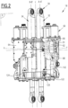
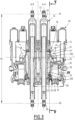
- the servo control 18 comprises a power device 30 configured to move the movable element 12 and a control device 60 configured to control the power device 30 as a function of the movement command for the movable element 12 received from the device 16 of aircraft 10.
- the servo control 18 further comprises a device 120 for connecting between the power device 30 and the control device 60.
- the power device 30 comprises at least one hydraulic cylinder 32 extending along a cylinder axis A-A'.
- the power device 30 comprises at least one additional hydraulic cylinder 34 identical to the hydraulic cylinder 32 and extending along an additional cylinder axis BB' substantially parallel to the cylinder axis A-A'.
- the power device 30 comprises exactly one hydraulic cylinder 32 and an additional hydraulic cylinder 34, fixed to one another substantially side by side in the plane P.
- At least part of the hydraulic cylinder 32 is made of a first material.
- the entire hydraulic cylinder 32 is made of the first material.
- the first material is an aluminum alloy, in particular a 2050, 2024 or 7175 aluminum alloy.
- the hydraulic cylinder 32 comprises a cylinder 38, a rod 54 and a piston 56.
- the hydraulic cylinder 32 further comprises a first ball joint 57 fixed in translation along the longitudinal axis L and a second ball joint 58 secured to the movable element 12 and movable in translation along the longitudinal axis L.
- the cylinder 38 extends along the cylinder axis A-A'.
- the at least part of the hydraulic cylinder 32 made of the first material comprises the cylinder 38.
- the cylinder 38 is made of the first material, the rod 54 and the piston 56 being made of a material different from the first material, for example stainless steel.
- the at least part of the hydraulic cylinder 32 made of the first material comprises the cylinder 38, the rod 54 and the piston 56.
- the cylinder 38 delimits a chamber 39 and comprises at least a first portion 40 and at least a second portion 42 for connection between the chamber 52 and a control unit 62 of the control device 60 (which will be described later).
- the chamber 39 comprises an upstream portion 39A and a downstream portion 39B and is intended to receive a fluid.
- the first 40 and second 42 connection portions of the cylinder 38 each comprise a cylindrical connection cavity 44 fluidly connected to the chamber 39 and to the control unit 62, in particular to a network 96 of tubular cavities 98 of the control unit (which will be described later).
- the cylindrical connection cavity 44 of the first connection portion 40 of the cylinder 38 is indicated on the Figure 4 .
- the cylinder 38 comprises a single first connection portion 40 and a single second connection portion 42.
- the first connection portion 40 of the cylinder 38 further comprises two connection members 46 with the connection device 120.
- the two bodies 46 are arranged on either side of the plane P.
- Each connecting member 46 comprises two plates 48 each extending substantially along a plane parallel to the transverse axis T and the vertical axis V and separated by a space 49 for receiving a wing 132 of a connecting piece 122 of the connecting device 120.
- the receiving space 49 is dimensioned such that the spacing between the plates 48 corresponds substantially to the thickness of the wing 132 measured along the longitudinal axis L.
- Each plate 48 includes an orifice 50 for the passage of a screw 140 of the connection device 120.
- the rod 54 extends along the cylinder axis A-A' in the chamber 39.
- the piston 56 is mounted on the rod 54 in the chamber 39.
- the piston 56 is integral with the rod 54.
- the piston 56 separates the upstream portion 39A and the downstream portion 39B of the chamber 39.
- the first ball joint 57 is fixed in translation along the longitudinal axis L and movable in rotation around a first axis of rotation R1 substantially parallel to the transverse axis T.
- the first ball joint 57 is integral with the cylinder 38.
- the second ball joint 58 is movable in translation along the longitudinal axis L and movable in rotation around a second axis of rotation R2 substantially parallel to the transverse axis T.
- the second ball joint 57 is integral with the piston.
- first R1 and second R2 axes of rotation are separated along the longitudinal axis L by a center distance EA.
- control device 60 comprises at least one control unit 62.
- control device 60 comprises at least one additional control unit 64 identical to the control unit 62 and associated with the at least one additional hydraulic cylinder 34.
- control device 60 comprises exactly one control unit 62 and one additional control unit 64.
- control device 60 is mounted on the power device 30.
- control unit 62 is mounted on the cylinder 38 of the hydraulic cylinder 32.
- additional control unit 64 is mounted on the cylinder of the additional hydraulic cylinder 34.
- the control unit 62 is fixed and fluidly, mechanically and electrically connected to the hydraulic cylinder 32 and the additional control unit 64 is fixed and fluidly connected to the additional hydraulic cylinder 34.
- the control unit 62 comprises a set 68 of electronic, mechanical and/or hydraulic accessories 70 and a body 72.
- the electronic, mechanical and/or hydraulic accessories 70 are arranged in the body 72, in particular in cavities for receiving the accessories 70.
- the accessories 70 are for example pistons, check valves, valves, pressure sensors, flow sensors, temperature sensors, distributions, accumulators.
- the body 72 delimits the network 96 of tubular cavities 98.
- the body 72 further comprises at least a first connection portion 76 between the network 96 and hydraulic cylinder 32, at least a second connection portion 78 between the network 96 and the hydraulic cylinder 32, at least one shaped portion 88 and an external surface 90.
- the body 72 of the control unit 62 is made of a second material distinct from the first material, advantageously by additive manufacturing.
- the second material is a titanium alloy, in particular a TA6V titanium alloy.
- first 76 and second 78 connection portions each comprise a cylindrical connection cavity 80 in fluid communication with the chamber 39 of the hydraulic cylinder 32.
- the cylindrical connection cavity 80 of the first connection portion 76 is indicated on the Figure 4 .
- the body 72 comprises a single first connection portion 76 and a single second connection portion 78.
- the first connection portion 76 of the body 72 is in fluid communication with the first connection portion 40 of the cylinder 38 and the second connection portion 78 of the body 72 is in fluid communication with the second connection portion 42 of the cylinder 38.
- the first 76 and second 78 connection portions of the body 72, in particular their respective cylindrical connection cavities 80, are connected by the set 68 of accessories 70.
- the first connection portion 76 of the body 72 further comprises two connection members 84 with the connection device 120.
- the cylindrical connection cavity 80 of the first 76 and/or the second 78 connection portions of the body 72 extends along an axis CC' (visible on the Figure 4 ) substantially parallel to the cylinder axis A-A'.
- the cylindrical connection cavity 80 of the first connection portion 76 of the body 72 extends along the axis C-C'.
- Each cylindrical connection cavity 80 is delimited by an internal wall 82.
- Each connecting member 84 comprises a plate 85 extending substantially along a plane parallel to the transverse axis T and the vertical axis V, in particular parallel to the plane of extension of the plates 48 of the connecting members 46 of the cylinder 32.
- Each plate 85 includes an orifice 86 for passing a screw 140 of the connecting device 120.
- the body 72 comprises at least one shaped portion 88, of which a portion 91 of corresponding external surface 90 matches the shape of at least one mechanical, electronic and/or hydraulic accessory 70 and/or at least one tubular cavity 98, in particular of at least one tubular cavity 98 having a curved neutral fiber 100.
- the shaped portion 88 allows a gain in mass and reduces pressure losses within the tubular cavity 98.
- the body 72 has less material than the body 7 of the state of the art since in the invention the surface 90 conforms to the shape of the accessories 70 and/or the tubular cavities 98.
- the surface 9 of the body 7 is substantially flat and does not conform to the shape or accessories 8 , nor tubular cavities 1, 2.
- the network 96 of tubular cavities 98 fluidly connects the accessories 70 to each other as well as the accessories 70 to the hydraulic cylinder 32.
- the network 96 of tubular cavities 98 fluidly connects the cylindrical connection cavities 80 of the first 76 and second 78 portions of fitting and accessories 70.
- Each tubular cavity 98 is delimited radially by an internal wall 106.
- Each tubular cavity 98 has no sharp edge between its ends 102, 104.
- the left part of the Figure 7 illustrates an example of the state of the art in which two tubular cavities 1, 2 have sharp edges between their ends 3, 4.
- At least one tubular cavity 98 is devoid of bifurcation and/or tapping between its ends 102, 104.
- the left part of the Figure 7 illustrates an example of the state of the art in which each tubular cavity 1, 2 has bifurcations and connections 5, 6.
- a neutral fiber 100 is defined for each tubular cavity 98.
- the neutral fiber 100 of a tubular cavity 98 corresponds to a line passing through the center of gravity of the straight sections of said tubular cavity 98.
- the neutral fiber 100 of at least one tubular cavity 98 is curved.
- Such a curved neutral fiber 100 is notably obtained thanks to the use of additive manufacturing during the process of producing the servo control 18 (detailed below).
- a plurality of tubular cavities 98 have a curved neutral fiber 100.
- the curved neutral fiber 100 extends along the shortest path between its two ends 102, 104, the shortest path being restricted by the presence of the other tubular cavities 98, the accessories 70 and the external surface 90. As illustrated on the example of the Figure 7 , the shortest path along which the curved neutral fiber 100 extends is restricted by the presence of the accessory 70C.
- the radius of curvature of the curved neutral fiber 100 is continuously derivable.
- connection device 120 comprises at least one connection part 122 between the network 96 of tubular cavities 98 of the control unit 62 and the hydraulic cylinder 32.
- connection device 120 comprises at least one additional connection part 124 identical to the connection part 122 and connecting the network 96 of tubular cavities 98 of the additional control unit 64 and the additional hydraulic cylinder 34.
- connection device 120 comprises exactly one connection part 122 and an additional connection part 124.
- connecting piece 122 is described. It is of course understood that what follows applies to all of the connecting pieces 122, when the connecting device 120 comprises a plurality connecting parts 122 and additional connecting parts 124.
- connection part 122 is arranged so as to be movable in translation in the cylindrical connection cavity 80 of the first connection portion 76 during the differential expansion of the body 72 of the control unit 62 and the hydraulic cylinder 32 l 'one in relation to the other.
- connection part 122 can be moved in translation in the cylindrical connection cavity 80 along the cylinder axis A-A'.
- connection part 122 comprises a cylindrical portion 128 for connection with the cylindrical cavity 80 of the first connection portion 76 of the control unit 62 and a cylindrical portion 130 for connection with the cylindrical cavity 44 of the first connection portion 40 of the hydraulic cylinder 32.
- the connecting part 122 further comprises two wings 132 extending laterally on either side of the cylindrical portions 128 and 130, in particular on either side of the plane P.
- the cylindrical connection portion 128 delimits a connection pipe 146 and extends into the cylindrical connection cavity 80.
- the cylindrical connection portion 128 further comprises at least one annular projection 148 extending radially from the connection pipe 146 and cooperating with the internal wall 82 delimiting the cylindrical connection cavity 80, to sealingly connect the network 96 of tubular cavities 98 of the control unit 62 and the hydraulic cylinder 32.
- each wing 132 is formed by a plate 134 extending substantially along a plane parallel to the transverse axis T and the vertical axis V.
- Each plate 134 includes an orifice 136 for passage of the screw 140.
- each screw 140 extends substantially parallel to the longitudinal axis L through the passage orifices 50 of the connecting members 46 of the jack 32, through the passage orifice 86 of the connecting member 84 of the body 72 of the unit control 62 and through the passage orifice 136 of the wings 132 of the connecting part 122.
- Each screw 140 cooperates with a nut 142 to secure the hydraulic cylinder 32, the connecting part 122 and the control unit 62 while allowing translation parallel to the longitudinal axis L of the hydraulic cylinder 32 and the control unit 62 in relation to each other.
- the connecting part 122 of the connecting device 120 and the connecting members 46, in particular the plates 48 slide together along the screw 140 between the connecting member 84 of the control unit 62, in particular the plate 85, and the head of the screw 140.
- control device 60 and the power device 30 can be made of materials of different natures and/or characteristics, by assembling one on top of the other.
- the connecting part 122 guarantees that the differential expansions likely to occur over the operating temperature range of the aircraft 10 are compensated.
- the screws 140 thus constitute an element allowing the joining of the cylinder 32, the control unit 62 and the connecting part 122 and the guidance in the longitudinal direction L of the hydraulic cylinder 32 relative to the control unit 62 during differential expansion.
- the method 200 comprises a first step 210 of forming the hydraulic cylinder 32 of the power device 30, for example by machining at least one block of the first material.
- the method 200 further comprises a second step 220 of producing a blank 71 of the body 72 of the control unit 62 by additive manufacturing in particular from the second material.
- the blank 71 of the body 72 comprises at least one tubular cavity 98 whose neutral fiber 100 is curved.
- the second step 220 is carried out so that at least one tubular cavity 98 has a curved neutral fiber 100.
- additive manufacturing makes it possible to obtain such a curved neutral fiber 100.
- the second step 220 does not use additive manufacturing supports.
- additive manufacturing supports we mean elements dedicated to supporting overhanging parts of the blank 71.
- the blank 71 is self-supporting.
- self-supporting we means that the blank 71 is devoid of overhanging parts or that it has overhanging parts which do not require particular supports.
- the blank 71 of the body 72 extends in a main direction D from the rear to the front.
- the main direction D is parallel to the cylinder axis AA' when the power device 30 and the control device 60 are assembled.
- Additive manufacturing is carried out in the main direction D from back to front during the second step 220.
- the blank 71 of the body 72 has at least one overhanging portion 160.
- overhang we mean that the portion 160 does not present any immediate support below it, that is to say backwards in the main direction D.
- any surface of the at least one portion 160 oriented substantially towards the rear in the main direction D has an angle ⁇ with the main direction D less than or equal to 45°. Such an angle makes it possible to dispense with additive manufacturing supports.
- a cantilevered portion 160 is indicated in the example of the Figure 9 .
- This overhanging portion corresponds to the upper part (forward in the main direction D) of an orifice blank 161.
- This upper part is an overhanging portion since it does not present any immediate support below .
- the upper surface of the orifice blank 161, which is oriented substantially rearwardly in the main direction D, has an angle ⁇ with the main direction D, as illustrated.
- the method 200 further comprises a third step 230 of producing the body 72 of the control unit 62 by machining the blank 71.
- the surfaces of the at least one portion 160 oriented substantially towards the rear are machined to give them their final shape.
- FIG. 10 illustrates an example consistent with that of the Figure 9 , in which the orifice blank 161 of the Figure 9 was machined to give it its final shape, that is to say the final shape of orifice 162.
- the method 200 further comprises a fourth step 240 of forming the control unit 62 of the control device 60 by installing the electronic, mechanical and/or hydraulic accessories 70 in the body 72.
- the method 200 further comprises a fifth step 250 of assembling the power device 30 and the control device 60 to form the servo control 18.
- the fifth step 250 comprises the arrangement of at least one connection device 120 between the power device 30 and the control device 60.
- the arrangement of the at least one connection device 120 between the power device 30 and the control device 60 comprises the arrangement of a connection part 122 between the network 96 of tubular cavities 98 and the hydraulic cylinder 32.
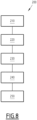
- Servo controls 18A, 18B, 18C of the 180 series of servo controls are as described above.
- Each servo control 18 of the series 180 of servo controls 18A, 18B, 18C is intended for controlling the position of a movable element 12 of the aircraft 10.
- Each servo control 18 of the series 180 of servo controls 18A, 18B, 18C comprises a power device 30 and a control device 60 capable of being assembled to form, in an assembled configuration, said servo control 18.
- the series 180 of servo controls 18A, 18B, 18C comprises a first servo control 18A and a second servo control 18B distinct from the first servo control 18A.
- the series 180 of servo controls 18A, 18B, 18C comprises a third servo control 18C distinct from the first servo control 18A.
- the third servo control 18C is also distinct from the second servo control 18B.
- the first servo control 18A is intended for controlling the position of a first movable element 12
- the second servo control 18B is intended for controlling the position of a second movable element 12 distinct from the first movable element 12
- the third servo control 18C is intended for controlling the position of a third mobile element 12 distinct from the first and second mobile elements 12.
- the power device 30X of the second servo control 18B is identical to the power device 30X of the first servo control 18A and the control device 60Y of the second servo control 18B is different from the control device 60X of the first servo control 18A.
- control unit 62U of the first servo control 18A is distinct from the control unit 62V of the second servo control 18B.
- the body 72 of the control unit 62U of the first servo control 18A is identical to the body 72 of the control unit 62V of the second servo control 18B and the set 68U of electronic, mechanical and/or hydraulic accessories 70 of the 62U control unit of the first servo control 18A is distinct from the 68V set of electronic, mechanical and/or hydraulic accessories 70 of the 62V control unit of the second servo control 18B.
- first 18A and second 18B servo controls are distinguished by the set 68 of electronic, mechanical and/or hydraulic accessories 70 but include identical bodies 72, and therefore networks 96 of identical tubular cavities 98.
- the power device 30Y of the third servo control 18C is different from the power device 30X of the first servo control 18A and the control device 60X of the third servo control 18C is identical to the control device 60X of the first servo control 18A.
- the power device 30X of the first servo control 18A has at least one differentiating characteristic compared to the power device 30Y of the third servo control 18C.
- the diameter of the hydraulic cylinder 32 corresponds to the diameter of the cylinder 38.
- the method 300 comprises a first step 310 of providing a plurality of distinct power devices 30X, 30Y.
- the method 300 further comprises a second step 320 of providing a plurality of distinct control devices 60X, 60Y.
- the second step 320 comprises a first sub-step 321 of providing a plurality of bodies 72 of identical control units 62.
- the second step 320 further comprises a second sub-step 322 for providing a plurality of first sets 68U of electronic, mechanical and/or hydraulic accessories 70 and a plurality of second sets 68V of electronic accessories, mechanical and/or hydraulic 70.
- the first sets 68U are distinct from the second sets 68V.
- the second step 320 further comprises a third sub-step 323 of forming a first control unit 62U by installing a first set 68U of electronic, mechanical and/or hydraulic accessories 70 in a body 72 of the control unit. control 62 and without installation of a second 68V set of electronic, mechanical and/or hydraulic accessories 70.
- the second step 320 further comprises a fourth step 324 of forming a second 62V control unit by installing a second 68V set of electronic, mechanical and/or hydraulic accessories 70 in a body 72 of the control unit 62 , for example without installation of a first set 68U of electronic, mechanical and/or hydraulic accessories 70.
- the method 300 further comprises a third step 330 of assembling a first combination of a power device 30 among the plurality of distinct power devices 30X, 30Y, 30Z and a control device 60 among the plurality of separate control devices 60X, 60Y, 60Z to form a first servo control 18A.
- the method 300 further comprises a fourth step 340 of assembling a second combination of a power device 30 among the plurality of distinct power devices 30X, 30Y, 30Z and a control device 60 among the plurality of separate control devices 60X, 60Y, 60Z to form a second servo control 18B.
- the second combination is distinct from the first combination.
- the first material is a steel, in particular a stainless steel or a titanium alloy.
- the cylinder 38, the rod 54 and the piston 56 are made of stainless steel.
- the second material is a steel, in particular a stainless steel, an Inconel TM or an aluminum alloy.
- the device 16 for generating the movement command of the mobile element 12 is a mechanical linkage.
- the servo control 18 offers improved adaptability and modularity as a function of the mobile element 12 to be controlled by the use of two distinct materials respectively for the hydraulic cylinder 32 and for the control unit 62.
- Servo control 18 allows for mass savings and manufacturing cycle savings (time savings).
- the body 72 includes a shaped portion, also obtained through the use of additive manufacturing, further reduces the mass and bulk of the body 72.
- connection device 120 in particular thanks to the connection part 122, the differential expansion of the body 72 of the control unit 62 and of the hydraulic cylinder 32 relative to each other is authorized, which reduces the stresses suffered by the servo control 18 and therefore extends its lifespan.
- the invention makes it possible to easily produce a multitude of servo controls 18 depending on various mobile elements 12 to be controlled.
- the 180 series servo controls according to the invention are distinguished by their power device and/or by their control device.
Landscapes
- Engineering & Computer Science (AREA)
- Physics & Mathematics (AREA)
- Fluid Mechanics (AREA)
- Automation & Control Theory (AREA)
- Aviation & Aerospace Engineering (AREA)
- Mechanical Engineering (AREA)
- General Engineering & Computer Science (AREA)
- Actuator (AREA)
- Control Of Position Or Direction (AREA)
- Feedback Control In General (AREA)
- Fluid-Pressure Circuits (AREA)
- Control Of Position, Course, Altitude, Or Attitude Of Moving Bodies (AREA)
Applications Claiming Priority (1)
| Application Number | Priority Date | Filing Date | Title |
|---|---|---|---|
| FR2300457A FR3144970B1 (fr) | 2023-01-18 | 2023-01-18 | Servocommande destinée au contrôle de la position d'un élément mobile d'un aéronef réalisée en deux matérieux distincts |
Publications (1)
| Publication Number | Publication Date |
|---|---|
| EP4403465A1 true EP4403465A1 (de) | 2024-07-24 |
Family
ID=86604086
Family Applications (1)
| Application Number | Title | Priority Date | Filing Date |
|---|---|---|---|
| EP24152195.4A Pending EP4403465A1 (de) | 2023-01-18 | 2024-01-16 | Servosteuerung zur positionssteuerung eines beweglichen elements eines luftfahrzeugs, das aus zwei verschiedenen materialien hergestellt ist |
Country Status (4)
| Country | Link |
|---|---|
| US (1) | US20240239479A1 (de) |
| EP (1) | EP4403465A1 (de) |
| CA (1) | CA3225853A1 (de) |
| FR (1) | FR3144970B1 (de) |
Citations (14)
| Publication number | Priority date | Publication date | Assignee | Title |
|---|---|---|---|---|
| FR1334999A (fr) * | 1962-06-07 | 1963-08-16 | Rech Etudes Prod | Dispositif de servo-commande hydraulique et son application à une commande de direction d'un avion |
| US3185167A (en) * | 1961-05-18 | 1965-05-25 | Sanders Associates Inc | Electro-hydraulic servo valve unit |
| FR2392262A1 (fr) * | 1977-05-26 | 1978-12-22 | United Technologies Corp | Commande perfectionnee a l'epreuve des coincements |
| US4138088A (en) * | 1976-12-30 | 1979-02-06 | Parker-Hannifin Corporation | Device for controlling hydraulic motors |
| US4466597A (en) * | 1981-12-02 | 1984-08-21 | Pneumo Corporation | Electro-mechanical direct drive valve servo system with rotary to linear valve drive mechanism |
| US5144801A (en) * | 1989-04-28 | 1992-09-08 | Parker Hannifin Corporation | Electro-hydraulic actuator system |
| US7048008B2 (en) * | 2004-04-13 | 2006-05-23 | Ultra Clean Holdings, Inc. | Gas-panel assembly |
| JP2012017839A (ja) * | 2010-07-09 | 2012-01-26 | Nabtesco Corp | 航空機用スリーブレス切替バルブ |
| US20160131165A1 (en) * | 2013-06-12 | 2016-05-12 | Blagdon Actuation Research Limited | Method for producing servo valve manifolds and manifold with curvilinear flow gallery of single piece construction |
| DE102016107170A1 (de) * | 2016-04-18 | 2017-10-19 | Airbus Operations Gmbh | Vorrichtung für ein hydraulisches System, System mit einer derartigen Vorrichtung sowie ein Flugzeug mit einem derartigen System |
| US20180335057A1 (en) * | 2017-05-16 | 2018-11-22 | Parker-Hannifin Corporation | Open Center Control Valve |
| DE102018126116A1 (de) * | 2018-10-19 | 2020-04-23 | Robert Bosch Gmbh | Hydraulischer Verteilerblock, hydraulisches Aggregat und Verfahren |
| DE102019210622A1 (de) * | 2019-06-27 | 2020-12-31 | Robert Bosch Gmbh | Hydraulik-Steuerblock und hydraulische Achse damit |
| US20220410864A1 (en) * | 2019-11-29 | 2022-12-29 | Knorr-Bremse Systeme für Schienenfahrzeuge GmbH | 3d printed manifold for a pneumatic control panel of a railway vehicle |
-
2023
- 2023-01-18 FR FR2300457A patent/FR3144970B1/fr active Active
-
2024
- 2024-01-11 CA CA3225853A patent/CA3225853A1/fr active Pending
- 2024-01-16 EP EP24152195.4A patent/EP4403465A1/de active Pending
- 2024-01-17 US US18/415,055 patent/US20240239479A1/en active Pending
Patent Citations (14)
| Publication number | Priority date | Publication date | Assignee | Title |
|---|---|---|---|---|
| US3185167A (en) * | 1961-05-18 | 1965-05-25 | Sanders Associates Inc | Electro-hydraulic servo valve unit |
| FR1334999A (fr) * | 1962-06-07 | 1963-08-16 | Rech Etudes Prod | Dispositif de servo-commande hydraulique et son application à une commande de direction d'un avion |
| US4138088A (en) * | 1976-12-30 | 1979-02-06 | Parker-Hannifin Corporation | Device for controlling hydraulic motors |
| FR2392262A1 (fr) * | 1977-05-26 | 1978-12-22 | United Technologies Corp | Commande perfectionnee a l'epreuve des coincements |
| US4466597A (en) * | 1981-12-02 | 1984-08-21 | Pneumo Corporation | Electro-mechanical direct drive valve servo system with rotary to linear valve drive mechanism |
| US5144801A (en) * | 1989-04-28 | 1992-09-08 | Parker Hannifin Corporation | Electro-hydraulic actuator system |
| US7048008B2 (en) * | 2004-04-13 | 2006-05-23 | Ultra Clean Holdings, Inc. | Gas-panel assembly |
| JP2012017839A (ja) * | 2010-07-09 | 2012-01-26 | Nabtesco Corp | 航空機用スリーブレス切替バルブ |
| US20160131165A1 (en) * | 2013-06-12 | 2016-05-12 | Blagdon Actuation Research Limited | Method for producing servo valve manifolds and manifold with curvilinear flow gallery of single piece construction |
| DE102016107170A1 (de) * | 2016-04-18 | 2017-10-19 | Airbus Operations Gmbh | Vorrichtung für ein hydraulisches System, System mit einer derartigen Vorrichtung sowie ein Flugzeug mit einem derartigen System |
| US20180335057A1 (en) * | 2017-05-16 | 2018-11-22 | Parker-Hannifin Corporation | Open Center Control Valve |
| DE102018126116A1 (de) * | 2018-10-19 | 2020-04-23 | Robert Bosch Gmbh | Hydraulischer Verteilerblock, hydraulisches Aggregat und Verfahren |
| DE102019210622A1 (de) * | 2019-06-27 | 2020-12-31 | Robert Bosch Gmbh | Hydraulik-Steuerblock und hydraulische Achse damit |
| US20220410864A1 (en) * | 2019-11-29 | 2022-12-29 | Knorr-Bremse Systeme für Schienenfahrzeuge GmbH | 3d printed manifold for a pneumatic control panel of a railway vehicle |
Also Published As
| Publication number | Publication date |
|---|---|
| FR3144970B1 (fr) | 2025-10-24 |
| CA3225853A1 (fr) | 2025-05-08 |
| FR3144970A1 (fr) | 2024-07-19 |
| US20240239479A1 (en) | 2024-07-18 |
Similar Documents
| Publication | Publication Date | Title |
|---|---|---|
| EP0477079B1 (de) | Hydrostatische Betätigungsvorrichtung, insbesondere als Sicherheitsvorrichtung und ein Flugsteuersystem, das eine solche Betätigungsvorrichtung enthält | |
| CA2661123C (fr) | Assemblage de panneaux et procede de montage d'un assemblage de panneaux | |
| FR2992629A1 (fr) | Dispositif de liaison mecanique d'une gouverne a un element structural fixe d'aeronef et element de voilure d'aeronef equipe de ce dispositif | |
| EP3350420A1 (de) | Motorkurbelgehäusestützvorrichtung und schnittstelle | |
| EP4403465A1 (de) | Servosteuerung zur positionssteuerung eines beweglichen elements eines luftfahrzeugs, das aus zwei verschiedenen materialien hergestellt ist | |
| EP4403464A1 (de) | Servosteuerung zur positionssteuerung eines beweglichen elements eines flugzeugs | |
| EP3404250A1 (de) | Hochdruckventil | |
| WO2021214411A1 (fr) | Gicleur de refroidissement de piston double jet en materiau plastique | |
| EP1816399A1 (de) | Verfahren zur Herstellung einer Brennkammer | |
| WO2019229352A1 (fr) | Architecture thermique de compresseur d'air | |
| EP1972798A1 (de) | Vorrichtung zur Positionssteuerung eines Stellglieds über ein Servoventil mit Positionsspeicher im Fall einer Panne | |
| EP2901069B1 (de) | Hydraulischer und elektrischer schnittstellenring für einen turbinenmotor | |
| EP1288480A1 (de) | Staustrahltriebwerk für Über- und Hyperschallflugzeug | |
| EP2892806B1 (de) | Hilfsantriebsgetriebe zur steuerung der auftriebsklappen eines flugzeugs | |
| EP3803080B1 (de) | Kurbelwelle für einen motor mit gesteuertem variablem verdichtungsverhältnis | |
| WO2017072457A1 (fr) | Systéme de pilotage en force et de contrôle d'attitude a compacité augmentée et engin comportant un tel système | |
| EP4172481B1 (de) | Schubumkehrvorrichtung mit drei toren | |
| FR3088374A1 (fr) | Guignol pour turbomachine | |
| FR3154138A1 (fr) | Carter porte tige de guidage | |
| FR3148632A1 (fr) | Adaptateur de pression amélioré pour système hydraulique | |
| EP3620685A1 (de) | Leistungsübertragungsorgan | |
| FR3163396A1 (fr) | Mecanisme de commande d’aubes de stator de turbomachine avec au moins un raidisseur | |
| FR3163399A1 (fr) | Mecanisme de commande d’aubes de stator de turbomachine avec au moins un raidisseur | |
| FR3018334A1 (fr) | Raccord hydraulique flexible pour une nacelle de turboreacteur, comportant un reglage de longueur | |
| EP4093979A1 (de) | Stellantrieb mit versetztem versorgungsanschluss |
Legal Events
| Date | Code | Title | Description |
|---|---|---|---|
| PUAI | Public reference made under article 153(3) epc to a published international application that has entered the european phase |
Free format text: ORIGINAL CODE: 0009012 |
|
| STAA | Information on the status of an ep patent application or granted ep patent |
Free format text: STATUS: THE APPLICATION HAS BEEN PUBLISHED |
|
| AK | Designated contracting states |
Kind code of ref document: A1 Designated state(s): AL AT BE BG CH CY CZ DE DK EE ES FI FR GB GR HR HU IE IS IT LI LT LU LV MC ME MK MT NL NO PL PT RO RS SE SI SK SM TR |
|
| STAA | Information on the status of an ep patent application or granted ep patent |
Free format text: STATUS: REQUEST FOR EXAMINATION WAS MADE |
|
| 17P | Request for examination filed |
Effective date: 20241226 |
|
| STAA | Information on the status of an ep patent application or granted ep patent |
Free format text: STATUS: EXAMINATION IS IN PROGRESS |
|
| 17Q | First examination report despatched |
Effective date: 20250929 |
|
| RAP3 | Party data changed (applicant data changed or rights of an application transferred) |
Owner name: DASSAULT AVIATION |