EP4403430A1 - Driving control method and driving control device - Google Patents
Driving control method and driving control device Download PDFInfo
- Publication number
- EP4403430A1 EP4403430A1 EP21957456.3A EP21957456A EP4403430A1 EP 4403430 A1 EP4403430 A1 EP 4403430A1 EP 21957456 A EP21957456 A EP 21957456A EP 4403430 A1 EP4403430 A1 EP 4403430A1
- Authority
- EP
- European Patent Office
- Prior art keywords
- vehicle
- lane
- driving
- subject vehicle
- driving assistance
- Prior art date
- Legal status (The legal status is an assumption and is not a legal conclusion. Google has not performed a legal analysis and makes no representation as to the accuracy of the status listed.)
- Withdrawn
Links
Images
Classifications
-
- B—PERFORMING OPERATIONS; TRANSPORTING
- B60—VEHICLES IN GENERAL
- B60W—CONJOINT CONTROL OF VEHICLE SUB-UNITS OF DIFFERENT TYPE OR DIFFERENT FUNCTION; CONTROL SYSTEMS SPECIALLY ADAPTED FOR HYBRID VEHICLES; ROAD VEHICLE DRIVE CONTROL SYSTEMS FOR PURPOSES NOT RELATED TO THE CONTROL OF A PARTICULAR SUB-UNIT
- B60W30/00—Purposes of road vehicle drive control systems not related to the control of a particular sub-unit, e.g. of systems using conjoint control of vehicle sub-units
- B60W30/18—Propelling the vehicle
- B60W30/18009—Propelling the vehicle related to particular drive situations
- B60W30/18163—Lane change; Overtaking manoeuvres
-
- B—PERFORMING OPERATIONS; TRANSPORTING
- B60—VEHICLES IN GENERAL
- B60W—CONJOINT CONTROL OF VEHICLE SUB-UNITS OF DIFFERENT TYPE OR DIFFERENT FUNCTION; CONTROL SYSTEMS SPECIALLY ADAPTED FOR HYBRID VEHICLES; ROAD VEHICLE DRIVE CONTROL SYSTEMS FOR PURPOSES NOT RELATED TO THE CONTROL OF A PARTICULAR SUB-UNIT
- B60W30/00—Purposes of road vehicle drive control systems not related to the control of a particular sub-unit, e.g. of systems using conjoint control of vehicle sub-units
- B60W30/10—Path keeping
- B60W30/12—Lane keeping
-
- B—PERFORMING OPERATIONS; TRANSPORTING
- B60—VEHICLES IN GENERAL
- B60W—CONJOINT CONTROL OF VEHICLE SUB-UNITS OF DIFFERENT TYPE OR DIFFERENT FUNCTION; CONTROL SYSTEMS SPECIALLY ADAPTED FOR HYBRID VEHICLES; ROAD VEHICLE DRIVE CONTROL SYSTEMS FOR PURPOSES NOT RELATED TO THE CONTROL OF A PARTICULAR SUB-UNIT
- B60W30/00—Purposes of road vehicle drive control systems not related to the control of a particular sub-unit, e.g. of systems using conjoint control of vehicle sub-units
- B60W30/14—Adaptive cruise control
-
- B—PERFORMING OPERATIONS; TRANSPORTING
- B60—VEHICLES IN GENERAL
- B60W—CONJOINT CONTROL OF VEHICLE SUB-UNITS OF DIFFERENT TYPE OR DIFFERENT FUNCTION; CONTROL SYSTEMS SPECIALLY ADAPTED FOR HYBRID VEHICLES; ROAD VEHICLE DRIVE CONTROL SYSTEMS FOR PURPOSES NOT RELATED TO THE CONTROL OF A PARTICULAR SUB-UNIT
- B60W30/00—Purposes of road vehicle drive control systems not related to the control of a particular sub-unit, e.g. of systems using conjoint control of vehicle sub-units
- B60W30/14—Adaptive cruise control
- B60W30/16—Control of distance between vehicles, e.g. keeping a distance to preceding vehicle
-
- B—PERFORMING OPERATIONS; TRANSPORTING
- B60—VEHICLES IN GENERAL
- B60W—CONJOINT CONTROL OF VEHICLE SUB-UNITS OF DIFFERENT TYPE OR DIFFERENT FUNCTION; CONTROL SYSTEMS SPECIALLY ADAPTED FOR HYBRID VEHICLES; ROAD VEHICLE DRIVE CONTROL SYSTEMS FOR PURPOSES NOT RELATED TO THE CONTROL OF A PARTICULAR SUB-UNIT
- B60W30/00—Purposes of road vehicle drive control systems not related to the control of a particular sub-unit, e.g. of systems using conjoint control of vehicle sub-units
- B60W30/18—Propelling the vehicle
- B60W30/182—Selecting between different operative modes, e.g. comfort and performance modes
-
- B—PERFORMING OPERATIONS; TRANSPORTING
- B60—VEHICLES IN GENERAL
- B60W—CONJOINT CONTROL OF VEHICLE SUB-UNITS OF DIFFERENT TYPE OR DIFFERENT FUNCTION; CONTROL SYSTEMS SPECIALLY ADAPTED FOR HYBRID VEHICLES; ROAD VEHICLE DRIVE CONTROL SYSTEMS FOR PURPOSES NOT RELATED TO THE CONTROL OF A PARTICULAR SUB-UNIT
- B60W60/00—Drive control systems specially adapted for autonomous road vehicles
-
- B—PERFORMING OPERATIONS; TRANSPORTING
- B60—VEHICLES IN GENERAL
- B60W—CONJOINT CONTROL OF VEHICLE SUB-UNITS OF DIFFERENT TYPE OR DIFFERENT FUNCTION; CONTROL SYSTEMS SPECIALLY ADAPTED FOR HYBRID VEHICLES; ROAD VEHICLE DRIVE CONTROL SYSTEMS FOR PURPOSES NOT RELATED TO THE CONTROL OF A PARTICULAR SUB-UNIT
- B60W60/00—Drive control systems specially adapted for autonomous road vehicles
- B60W60/005—Handover processes
- B60W60/0051—Handover processes from occupants to vehicle
-
- B—PERFORMING OPERATIONS; TRANSPORTING
- B60—VEHICLES IN GENERAL
- B60W—CONJOINT CONTROL OF VEHICLE SUB-UNITS OF DIFFERENT TYPE OR DIFFERENT FUNCTION; CONTROL SYSTEMS SPECIALLY ADAPTED FOR HYBRID VEHICLES; ROAD VEHICLE DRIVE CONTROL SYSTEMS FOR PURPOSES NOT RELATED TO THE CONTROL OF A PARTICULAR SUB-UNIT
- B60W2552/00—Input parameters relating to infrastructure
- B60W2552/10—Number of lanes
-
- B—PERFORMING OPERATIONS; TRANSPORTING
- B60—VEHICLES IN GENERAL
- B60W—CONJOINT CONTROL OF VEHICLE SUB-UNITS OF DIFFERENT TYPE OR DIFFERENT FUNCTION; CONTROL SYSTEMS SPECIALLY ADAPTED FOR HYBRID VEHICLES; ROAD VEHICLE DRIVE CONTROL SYSTEMS FOR PURPOSES NOT RELATED TO THE CONTROL OF A PARTICULAR SUB-UNIT
- B60W2554/00—Input parameters relating to objects
- B60W2554/40—Dynamic objects, e.g. animals, windblown objects
- B60W2554/404—Characteristics
- B60W2554/4042—Longitudinal speed
-
- B—PERFORMING OPERATIONS; TRANSPORTING
- B60—VEHICLES IN GENERAL
- B60W—CONJOINT CONTROL OF VEHICLE SUB-UNITS OF DIFFERENT TYPE OR DIFFERENT FUNCTION; CONTROL SYSTEMS SPECIALLY ADAPTED FOR HYBRID VEHICLES; ROAD VEHICLE DRIVE CONTROL SYSTEMS FOR PURPOSES NOT RELATED TO THE CONTROL OF A PARTICULAR SUB-UNIT
- B60W2554/00—Input parameters relating to objects
- B60W2554/80—Spatial relation or speed relative to objects
-
- B—PERFORMING OPERATIONS; TRANSPORTING
- B60—VEHICLES IN GENERAL
- B60W—CONJOINT CONTROL OF VEHICLE SUB-UNITS OF DIFFERENT TYPE OR DIFFERENT FUNCTION; CONTROL SYSTEMS SPECIALLY ADAPTED FOR HYBRID VEHICLES; ROAD VEHICLE DRIVE CONTROL SYSTEMS FOR PURPOSES NOT RELATED TO THE CONTROL OF A PARTICULAR SUB-UNIT
- B60W2554/00—Input parameters relating to objects
- B60W2554/80—Spatial relation or speed relative to objects
- B60W2554/804—Relative longitudinal speed
Definitions
- the present invention relates to a driving control method and a driving control device.
- a driving control method disclosed in Patent Document 1 is a method for controlling driving of a subject vehicle at a predetermined driving assistance level under the condition that the subject vehicle follows a preceding vehicle.
- Patent Document 1 JP 2020-104802 A
- a problem to be solved by the present invention is to provide a driving control method and a driving control device capable of executing lane-change control while maintaining a predetermined driving assistance level when a subject vehicle traveling behind a preceding vehicle at the driving assistance level changes a lane.
- the present invention solves the above-described problem by, in a case where a subject vehicle traveling in a first lane at a predetermined driving assistance level changes a lane to a second lane, keeping traveling of the subject vehicle in the first lane until another vehicle is detected in the second lane when the other vehicle is not detected in the second lane, and executing lane-change control at the predetermined driving assistance level after the other vehicle is detected.
- the present invention provides an effect that, since the lane-change control is executed after the other vehicle is detected in the second lane, the lane-change control can be executed while maintaining the predetermined driving assistance level when the subject vehicle traveling behind the preceding vehicle at the driving assistance level changes the lane.
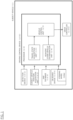
- FIG. 1 is a block diagram illustrating a configuration of a subject vehicle 1 and a driving control device 100 that controls autonomous driving of the subject vehicle 1.
- the subject vehicle 1 includes the driving control device 100, a detection device 101, a subject vehicle position acquisition unit 102, a map database 103, on-board devices 104, an input device 105, and a drive controller 106.
- the driving control device 100 executes a program stored in a ROM by a CPU, thereby autonomously controlling the vehicle speed and steering of the subject vehicle 1 by an autonomous travel control function.
- the driving control device 100 can set a driving mode corresponding to a driving assistance level, and can assist the travel of the subject vehicle according to the set driving mode.
- the driving assistance level indicates the degree of intervention when the driving control device 100 assists the driving of a vehicle by means of the autonomous travel control function.
- the driver's contribution to the driving of the vehicle decreases as the driving assistance level increases.
- the driving assistance level can be set to levels 0 to 5 using the definitions or the like based on SAE J3016 of the Society of Automotive Engineers (SAE).
- the driving control device 100 In the level 0, all of the driving operations of the subject vehicle are carried out manually by a driver. In the level 1, although the driving operations of the subject vehicle are primarily carried out by means of manual driving of the driver, the driving control device 100 appropriately assists the manual driving of the driver by means of any of functions such as automatic braking, following, and lane keeping. In the level 2, although the driving operations of the subject vehicle are primarily carried out by means of the manual driving of the driver, under specific conditions, the driving control device 100 can combine a plurality of functions from among an automatic brake function, a following function, a lane keeping function, and the like, thereby executing driving assistance. In the level 3, the driving control device 100 executes all of the driving tasks, but the driver must resume control and be prepared to drive manually when requested by the driving control device 100.
- the driving control device 100 can execute all of the driving tasks and monitor the surrounding conditions of the subject vehicle under specific conditions.
- the driving control device 100 can execute all of the driving tasks under all conditions.
- the driving control device 100 switches the above-described driving assistance level automatically or by the driver's operation.
- the driving mode corresponding to the level 2 is an eyes-on mode. That is, when the driving assistance level is set to the level 2, the driver needs to visually monitor the surrounding conditions of the subject vehicle 1. When the driving assistance level is set to the level 2, the face direction and the eye movement of the driver are monitored by an in-vehicle camera or the like, and the subject vehicle 1 is allowed to travel when the driver visually confirms the front. Additionally, the driving mode corresponding to the level 2 is a hands-on mode.
- the hands-on mode is a mode in which autonomous steering control by a processor 10 does not operate when the driver is not holding a steering wheel 104a. Whether the driver is holding the steering wheel 104a is detected by a touch sensor (not illustrated) provided on the steering wheel 104a or a steering torque sensor (not illustrated) of EPS.
- the "driver holding the steering wheel 104a” includes not only a state in which the driver is firmly gripping the steering wheel 104a, but also a state in which the driver is lightly touching the steering wheel 104a.
- the driving mode corresponding to the level 3 is an eyes-off mode. That is, when the driving assistance level is set to the level 3, the processor 10 controls the driving of the subject vehicle 1 by the eyes-off mode that permits the subject vehicle 1 to travel in a state where the driver does not visually confirm the front. At this time, the system of the driving control device 100 uses a camera, a radar, or the like to autonomously monitor the surrounding conditions of the subject vehicle. Additionally, the driving mode corresponding to the level 3 is a hands-off mode.
- the hands-off mode is a mode in which steering control by the processor 10 operates even if driver's hold on the steering wheel 104a is released.
- the processor 10 controls the driving of the subject vehicle 1 by the hands-off mode that permits the subject vehicle 1 to travel in a state where driver's hold on the steering wheel of the subject vehicle 1 is released.
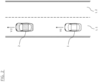
- the driving control device 100 can execute the driving mode corresponding to the level 3 under the condition that the subject vehicle 1 travels behind a preceding vehicle 2 as illustrated in FIG. 2 .
- the "subject vehicle 1 traveling behind the preceding vehicle 2" includes not only a state in which the subject vehicle 1 travels by following the preceding vehicle 2, but also a state in which the subject vehicle 1 travels behind the preceding vehicle 2 on a travel route on which the preceding vehicle 2 has already traveled without following the preceding vehicle 2. This allows the driving control device 100 to confirm that there is no obstacle on the travel route on which the preceding vehicle 2 has already traveled, that is, in front of the subject vehicle 1 to control the driving of the subject vehicle 1.
- the "subject vehicle 1 traveling by following the preceding vehicle 2" means that the subject vehicle 1 travels in a state where the driving control device 100 controls the driving of the subject vehicle 1 so as to be linked to the movement of the preceding vehicle 2, and controls a vehicle speed V1 of the subject vehicle 1 so as to keep a constant distance between the subject vehicle 1 and the preceding vehicle 2.
- the classification of the driving assistance levels is not limited to the classification according to the definitions of the Society of Automotive Engineers, and the driving assistance levels may be defined based on ISO/TC204 of the International Organization for Standardization (ISO). Further, the classification of the driving assistance levels may be defined by other criteria as long as they are appropriately classified in accordance with the degree of intervention of the driving control device 100.
- the detection device 101 includes any one or both of a vehicle-mounted camera that photographs surroundings of the subject vehicle 1 or a radar that detects other vehicles and obstacles around the subject vehicle.
- the detection result of the detection device 101 is output to the driving control device 100 at prescribed time intervals.
- the subject vehicle position acquisition unit 102 includes a GPS unit, a gyro sensor, a vehicle speed sensor, and the like.
- the subject vehicle position acquisition unit 102 detects radio waves transmitted from a plurality of communication satellites by means of the GPS unit, periodically acquires position information about the subject vehicle 1, and detects the current location of the subject vehicle 1 based on the acquired position information about the subject vehicle 1, angle change information acquired from the gyro sensor, and the vehicle speed acquired from the vehicle speed sensor.
- the position information about the subject vehicle 1 detected by the subject vehicle position acquisition unit 102 is output to the driving control device 100 at prescribed time intervals.
- the map database 103 is a memory configured to store high-precision three-dimensional map information that includes position information about various facilities and specific points, and to be accessible from the driving control device 100.
- the map database 103 stores high-precision digital map information (high-precision map, dynamic map).
- the high-precision map information includes identification information about a plurality of lanes on roads.
- the map information of the map database 103 includes three-dimensional position information about curved roads and/or lanes as well as the sizes of the curves (for example, the curvature or the radius of curvature), merging points, branch points, and lane reduction locations.
- the high-precision map information also includes information regarding facilities, such as service areas and parking areas.
- the on-board devices 104 are various devices mounted in the vehicle and function by means of the driver's operation.
- the on-board devices 104 include a steering wheel 104a.
- examples of the other on-board devices 104 include an accelerator pedal, a brake pedal, a navigation device, turn signal indicators, wipers, lights, a horn, and other specific switches.
- the driver operates the on-board devices 104, the information is output to the driving control device 100.
- the drive controller 106 controls the operation of the subject vehicle 1 based on a control command from the driving control device 100.
- the drive controller 106 controls the operation of a drive mechanism (including the operation of an internal combustion engine in a vehicle with an engine and the operation of a travel motor in an electric vehicle system, and including torque distribution between an internal combustion engine and a travel motor in a hybrid vehicle) and the braking operation for adjusting the acceleration/deceleration and the vehicle speed by means of an autonomous speed control function.
- the drive controller 106 controls the operation of a steering actuator by means of an autonomous steering control function, thereby executing steering control of the subject vehicle.
- the drive controller 106 detects a lane marker of a lane in which the subject vehicle travels and controls the travel position (lateral position) of the subject vehicle in the road width direction so that the subject vehicle travels in the center of the lane. Further, the drive controller 106 controls overtaking of a vehicle traveling ahead of the subject vehicle, changes in the travel direction of the subject vehicle, and the like. Further, the drive controller 106 carries out travel control for turning right or left at an intersection or the like. Further, other known methods can be used as the driving control method carried out by the drive controller 106.
- a "predetermined driving assistance level” is set to the level 3, but is not limited to this.
- the driving control device 100 can set a driving mode corresponding to another driving assistance level in addition to the level 3.
- the driving control device 100 includes the processor 10.
- the processor 10 includes the Read Only Memory (ROM) that stores a program for controlling the driving of the subject vehicle 1, the Central Processing Unit (CPU) that executes the program stored in this ROM, and a Random Access Memory (RAM) that functions as an accessible storage device.
- ROM Read Only Memory
- CPU Central Processing Unit
- RAM Random Access Memory
- a Micro Processing Unit (MPU), a Digital Signal Processor (DSP), an Application Specific Integrated Circuit (ASIC), a Field Programmable Gate Array (FPGA), and the like can be used in place of or in addition to the Central Processing Unit (CPU).
- the processor 10 includes a travel state acquisition unit 13, an adjacent other vehicle determination unit 14, and a vehicle control unit 15. The travel state acquisition unit 13, the adjacent other vehicle determination unit 14, and the vehicle control unit 15 execute programs for achieving the respective functions of the processor 10.
- the driving control device 100 is mounted in the subject vehicle 1 in FIG. 1 , it is not limited thereto, and the driving control device 100 may be a device that remotely operates the subject vehicle 1.
- the travel state acquisition unit 13 acquires the travel state, such as the vehicle speed V1, the acceleration/deceleration, and the driving assistance level of the subject vehicle 1.
- the travel state acquisition unit 13 determines whether the subject vehicle 1 is traveling behind the preceding vehicle 2 at the predetermined driving assistance level (for example, the level 3) as illustrated in FIG. 2 .
- the vehicle speed V1 of the subject vehicle 1 and a vehicle speed V2 of the preceding vehicle 2 are the same speed.
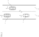
- the adjacent other vehicle determination unit 14 determines whether another vehicle 3 is detected in a second lane L2 adjacent to a first lane L1 in which the subject vehicle 1 is traveling as illustrated in FIG. 3 . When it is determined that the other vehicle 3 is detected, the adjacent other vehicle determination unit 14 acquires a vehicle speed V3 of the other vehicle 3. The adjacent other vehicle determination unit 14 may determine that the other vehicle 3 is detected in the second lane L2 when the vehicle speed V3 of the other vehicle 3 is higher than the vehicle speed V1 of the subject vehicle 1. That is, the adjacent other vehicle determination unit 14 does not need to perform a process of determining that the other vehicle 3 is detected in the second lane L2 when the vehicle speed V3 of the other vehicle 3 is equal to or less than the vehicle speed V1 of the subject vehicle 1.
- the adjacent other vehicle determination unit 14 may determine that the other vehicle 3 is detected when it is confirmed that the other vehicle 3 is present in front of the subject vehicle 1 in the second lane L2 by any infrastructure information communication means including vehicle-to-vehicle communication and road-to-vehicle communication.
- the second lane L2 is not limited to a lane adjacent to the first lane L1, and only needs to be a lane different from the first lane L1.
- the vehicle control unit 15 keeps the traveling of the subject vehicle 1 in the first lane L1 until the other vehicle 3 is detected in the second lane L2 when the other vehicle 3 is not detected in the second lane L2 as illustrated in FIG. 2 , and executes lane-change control of the subject vehicle 1 at the driving assistance level of the level 3 as illustrated in FIG. 3 after the other vehicle 3 is detected.
- the vehicle control unit 15 may execute the lane-change control at the driving assistance level of the level 3 when the vehicle speed V3 of the other vehicle 3 is higher than the vehicle speed V1 of the subject vehicle 1 (when it is determined that the other vehicle 3 is detected).
- the vehicle control unit 15 may control the driving of the subject vehicle 1 so as not to execute the lane-change control at the driving assistance level of the level 3 when the vehicle speed V3 of the other vehicle 3 is equal to or less than the vehicle speed V1 of the subject vehicle 1 (when it is determined that the other vehicle 3 is not detected). Further, the vehicle control unit 15 maintains the level 3 until a predetermined time elapses after the execution of the lane-change control at the driving assistance level of the level 3 is started.
- the predetermined time is time from the start of a lane change of the subject vehicle 1 until the distance between the subject vehicle 1 and the other vehicle 3 becomes a predetermined distance or less.
- the predetermined time for maintaining the driving assistance level at the level 3 is time until the distance between the subject vehicle 1 and the other vehicle 3 becomes the predetermined distance or less when the subject vehicle 1 accelerates at a predetermined acceleration after the lane change.
- the predetermined distance may be, for example, an upper limit value of a distance that the subject vehicle 1 can travel by following the other vehicle 3.
- the predetermined time may be time until the vehicle speed V1 of the subject vehicle 1 that has accelerated at the predetermined acceleration after the lane change reaches a predetermined speed limit.
- the speed limit is an upper limit value of the vehicle speed set for each road.
- the predetermined time may be time until it is confirmed that at least two or more other vehicles 3 have passed on a planned travel route of the subject vehicle 1 in the second lane L2 by any infrastructure information communication means including vehicle-to-vehicle communication and road-to-vehicle communication. In this case, the larger the number of the other vehicles 3 that have passed on the planned travel route of the subject vehicle 1 in the second lane L2, the longer the predetermined time may be set.
- the vehicle control unit 15 does not start the execution of the lane-change control at the level 3 when the vehicle speed V3 of the other vehicle 3 is higher than the vehicle speed V1 of the subject vehicle 1, and the vehicle speed V3 of the other vehicle 3 is higher than a predetermined value. That is, the vehicle control unit 15 decreases the driving assistance level to the level 2 before executing the lane-change control when the vehicle speed V3 of the other vehicle 3 is higher than the vehicle speed V1 of the subject vehicle 1, and the vehicle speed V3 of the other vehicle 3 is higher than the predetermined value.
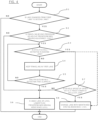
- Steps S1 to S8 of FIG. 4 The control indicated by Steps S1 to S8 of FIG. 4 is executed, for example, when a traffic jam is present in the first lane L1, and when the subject vehicle 1 changes the lane to the second lane L2 to perform overtaking, but is not limited to this.
- Step S1 the processor 10 determines whether the subject vehicle 1 changes the lane from the first lane L1 to the second lane L2 based on the planned travel route of the subject vehicle 1, the map information of the map database 103, the presence or absence of the obstacle detected by the detection device 101, and the like.
- the control ends.
- Step S2 the processor 10 determines whether the subject vehicle 1 is traveling behind the preceding vehicle 2 at the predetermined driving assistance level (level 3). When the subject vehicle 1 is not traveling behind the preceding vehicle 2 at the level 3, in Step S6, the processor 10 performs the lane-change control of the subject vehicle 1 at a driving assistance level (for example, the level 2) lower than the predetermined driving assistance level.
- a driving assistance level for example, the level 2
- Step S3 the adjacent other vehicle determination unit 14 determines whether the other vehicle 3 is detected in the second lane L2.
- the processor 10 determines whether the vehicle speed V3 of the other vehicle 3 is equal to or less than the predetermined value (for example, a vehicle speed limit). Since the predetermined value is higher than the vehicle speed V1 of the subject vehicle 1, when the vehicle speed V3 of the other vehicle 3 is higher than the predetermined value, the vehicle speed V3 of the other vehicle 3 is higher than the vehicle speed V1 of the subject vehicle 1.
- the predetermined value for example, a vehicle speed limit
- Step S6 the processor 10 performs the lane-change control of the subject vehicle 1 at a level (for example, the level 2) lower than the predetermined driving assistance level (level 3). Meanwhile, when the vehicle speed V3 of the other vehicle 3 is equal to or less than the predetermined value, in Step S8, the processor 10 performs the lane-change control of the subject vehicle 1 at the level 3. That is, the processor 10 does not execute the lane-change control of the subject vehicle 1 at the predetermined driving assistance level when the vehicle speed V3 of the other vehicle 3 is higher than the predetermined value.
- Step S3 when the adjacent other vehicle determination unit 14 determines that the other vehicle 3 is not detected in the second lane L2, in Step S4, the vehicle control unit 15 keeps the traveling of the subject vehicle 1 in the first lane L1. Then, in Step S5, whether a predetermined detection time has elapsed is determined, and when the predetermined detection time has not elapsed, the process returns to Step S3. That is, when the other vehicle 3 is not detected in the second lane L2, the processor 10 keeps the traveling of the subject vehicle 1 in the first lane L1 until the other vehicle 3 is detected in the second lane L2 unless the predetermined detection time elapses.
- Step S5 when it is determined that the predetermined detection time has elapsed while the other vehicle 3 is not detected in the second lane L2, in Step S6, the processor 10 executes the lane-change control of the subject vehicle 1 at the level (for example, the level 2) lower than the predetermined driving assistance level (level 3).
- the processor 10 may skip the process of Step S7. That is, when the other vehicle 3 is detected in the second lane L2 in Step S3, the processor 10 may execute the lane-change control at the level 3 regardless of the vehicle speed V3 of the other vehicle 3 in Step S8.
- the processor 10 of the driving control device 100 determines whether the other vehicle 3 is detected in the second lane L2 when the subject vehicle 1 traveling behind the preceding vehicle 2 in the first lane at the predetermined driving assistance level changes the lane to the second lane. Then, when the other vehicle 3 is not detected, the processor 10 keeps the traveling of the subject vehicle 1 in the first lane L1 until the other vehicle 3 is detected, and executes the lane-change control at the predetermined driving assistance level after the other vehicle 3 is detected. This allows the driving control device 100 to execute the lane-change control while maintaining the driving assistance level when the subject vehicle 1 traveling behind the preceding vehicle 2 at the predetermined driving assistance level changes the lane.
- the driving control device 100 can execute the lane-change control without decreasing the driving assistance level when the subject vehicle 1 changes the lane. Additionally, by the detection of the other vehicle traveling in the second lane L2, the subject vehicle 1 can change the lane toward the second lane L2 in which an obstacle is less likely to be present in a driving mode corresponding to the predetermined driving assistance level.
- the processor 10 of the driving control device 100 executes the lane-change control at the predetermined driving assistance level when the vehicle speed V3 of the other vehicle 3 is higher than the vehicle speed V1 of the subject vehicle 1. Meanwhile, when the vehicle speed V3 of the other vehicle 3 is equal to or less than the vehicle speed V1 of the subject vehicle 1, the processor 10 does not execute the lane-change control at the predetermined driving assistance level. That is, the driving control device 100 determines that the other vehicle 3 is detected in the second lane L2 and executes the lane-change control at the predetermined driving assistance level when the vehicle speed V3 of the other vehicle 3 is higher than the vehicle speed V1 of the subject vehicle 1.
- the driving control device 100 determines that the other vehicle 3 is not detected at the second lane L2, and does not execute the lane-change control at the predetermined driving assistance level. This allows the subject vehicle 1 to change the lane to the second lane L2 and accelerate to approach the other vehicle 3 and travel behind the other vehicle 3 in the second lane L2 in a driving mode corresponding to the predetermined driving assistance level.
- the processor 10 of the driving control device 100 maintains the predetermined driving assistance level until the predetermined time elapses after the execution of the lane-change control at the predetermined driving assistance level is started. This allows the driving control device 100 to control the driving of the subject vehicle 1 without decreasing the driving assistance level until the predetermined time elapses regardless of whether the traveling environment of the subject vehicle 1 meets the condition for the traveling of the subject vehicle 1 at the predetermined driving assistance level.
- the above-described predetermined time is time from the start of the execution of the lane-change control by the processor 10 until the distance between the subject vehicle 1 and the other vehicle 3 becomes the predetermined distance or less. This allows the driving control device 100 to maintain the predetermined driving assistance level until the subject vehicle 1 that has changed the lane comes to be able to travel behind the other vehicle 3 with a predetermined inter-vehicular distance.
- the above-described predetermined distance may be the upper limit value of the distance that the subject vehicle 1 can travel by following the other vehicle 3. This allows the driving control device 100 to maintain the predetermined driving assistance level until the subject vehicle 1 that has changed the lane comes to be able to travel by following the other vehicle 3.
- the above-described predetermined time may be time from the start of the execution of the lane-change control by the processor 10 until the vehicle speed V1 of the subject vehicle 1 reaches the predetermined speed limit. This allows the driving control device 100 to maintain the predetermined driving assistance level until the subject vehicle 1 comes to be able to travel behind the other vehicle 3 traveling at the speed limit or less with the predetermined inter-vehicular distance.
- the processor 10 of the driving control device 100 does not execute the lane-change control at the predetermined driving assistance level when the vehicle speed V3 of the other vehicle 3 is higher than the vehicle speed V1 of the subject vehicle 1, and the vehicle speed V3 of the other vehicle 3 is higher than the predetermined value. Accordingly, when the subject vehicle 1 that has changed the lane is less likely to be allowed to travel behind the other vehicle 3 at the predetermined driving assistance level, the driving control device 100 executes the lane-change control at a decreased driving assistance level.
- the processor 10 of the driving control device 100 controls the driving of the subject vehicle 1 by the hands-off mode that autonomously executes the steering control allowing the subject vehicle 1 to travel in the state where driver's hold on the steering wheel of the subject vehicle 1 is released. This allows the driving control device 100 to control the driving of the subject vehicle 1 by the hands-off mode when the driving of the subject vehicle 1 is controlled at the predetermined driving assistance level (for example, the level 3), thus reducing a driving load on the driver.
- the predetermined driving assistance level for example, the level 3
- the processor 10 of the driving control device 100 controls the driving of the subject vehicle 1 by the eyes-off mode that permits the subject vehicle 1 to travel in the state where the driver does not visually confirm the front. This allows the driving control device 100 to control the driving of the subject vehicle 1 by the eyes-off mode when the driving of the subject vehicle 1 is controlled at the predetermined driving assistance level (for example, the level 3), thus reducing a driving load on the driver.
- the predetermined driving assistance level for example, the level 3
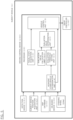
- FIG. 5 is a block diagram illustrating a configuration of a driving control device 200 according to a second embodiment.
- FIG. 5 is a block diagram illustrating a configuration of a driving control device 200 according to a second embodiment.
- the same reference numerals as the reference numerals illustrated in FIG. 1 indicate the similar configurations, their detailed descriptions will be omitted.
- a processor 20 of the driving control device 200 includes an evaluation value calculation unit 21, an evaluation threshold setting unit 22, and an evaluation value determination unit 23 in addition to the travel state acquisition unit 13, the adjacent other vehicle determination unit 14, and the vehicle control unit 15.
- the evaluation value calculation unit 21 calculates an evaluation value that indicates a sufficiency level of a condition for the subject vehicle 1 to travel at the predetermined driving assistance level.
- Examples of the condition for the subject vehicle 1 to travel at the predetermined driving assistance level include that the subject vehicle 1 is traveling at a predetermined set speed or less, that the inter-vehicular distance between the subject vehicle 1 and the preceding vehicle 2 or the other vehicle 3 is the predetermined distance or less, that a traffic jam is present around the subject vehicle 1, that the subject vehicle 1 is traveling on a road for which using high-precision map information is effective, that Global Navigation Satellite System (GNSS) signals are effective, that the driver visually confirms the front, that there are no toll booths, motorway exits, merging points, intersections, or lane reduction points in the vicinity of the current location (for example, within about 800 m ahead), and that there are no sharp curves of 100 R or less in the vicinity of the current location (for example, within about 500 m ahead).
- GNSS Global Navigation Satellite System
- An evaluation value calculation unit 21 calculates the evaluation value based on one or a plurality of conditions among the above-described conditions. For example, the evaluation value calculation unit 21 may calculate the sufficiency level for each of the plurality of conditions described above, and sum up the calculated sufficiency levels to calculate the evaluation value.
- the evaluation threshold setting unit 22 sets an evaluation threshold as a criterion for determining whether the subject vehicle 1 can travel at the predetermined driving assistance level. That is, the evaluation threshold setting unit 22 sets a value corresponding to the condition for the subject vehicle 1 to travel at the predetermined driving assistance level as the evaluation threshold.
- the evaluation threshold setting unit 22 selects a second evaluation threshold lower than a first evaluation threshold in a case where the subject vehicle 1 is traveling in the first lane L1 at the predetermined driving assistance level as the evaluation threshold.
- the evaluation threshold setting unit 22 relaxes the condition for the subject vehicle 1 to travel at the predetermined driving assistance level compared with a case where the subject vehicle 1 is traveling without changing the lane.
- the evaluation value determination unit 23 compares the evaluation value calculated by the evaluation value calculation unit 21 with the evaluation threshold set by the evaluation threshold setting unit 22 to determine whether the evaluation value is equal to or less than the evaluation threshold. Specifically, when the inter-vehicular distance between the subject vehicle 1 and the preceding vehicle 2 or the other vehicle 3 becomes the predetermined inter-vehicular distance or more, the evaluation value determination unit 23 determines that the evaluation value has become the evaluation threshold or less.
- a predetermined inter-vehicular distance (for example, a distance corresponding to an inter-vehicle time of 10 seconds) when the subject vehicle 1 changes the lane at the predetermined driving assistance level after the other vehicle 3 is detected is set to be longer than a predetermined inter-vehicular distance (for example, a distance corresponding to an inter-vehicle time of 3 seconds) when the subject vehicle 1 is traveling in the first lane L1 at the predetermined driving assistance level.
- the vehicle control unit 15 changes the driving assistance level to a lower level when the evaluation value determination unit 23 determines that the evaluation value has become the evaluation threshold or less. For example, the vehicle control unit 15 changes the driving assistance level from the level 3 to the level 2 when the evaluation value becomes the evaluation threshold or less.
- the processor 20 of the driving control device 200 calculates the evaluation value that indicates the sufficiency level of the condition for the subject vehicle 1 to travel at the predetermined driving assistance level.
- the processor 20 selects the second evaluation threshold lower than the first evaluation threshold in the case where the subject vehicle 1 is traveling in the first lane L1 at the predetermined driving assistance level as the evaluation threshold. Then, the processor 20 changes the driving assistance level to a lower level when the evaluation value has become the evaluation threshold or less.
- the processor 20 relaxes the condition for the subject vehicle 1 to travel at the predetermined driving assistance level compared with the case where the subject vehicle 1 is traveling without changing the lane. This allows the driving control device 200 to control the driving of the subject vehicle 1 in a state where the driving assistance level is less likely to be decreased when the subject vehicle 1 changes the lane to the second lane L2 at the predetermined driving assistance level.
Landscapes
- Engineering & Computer Science (AREA)
- Automation & Control Theory (AREA)
- Transportation (AREA)
- Mechanical Engineering (AREA)
- Human Computer Interaction (AREA)
- Traffic Control Systems (AREA)
- Control Of Driving Devices And Active Controlling Of Vehicle (AREA)
Abstract
Description
- The present invention relates to a driving control method and a driving control device.
- A driving control method disclosed in
Patent Document 1 is a method for controlling driving of a subject vehicle at a predetermined driving assistance level under the condition that the subject vehicle follows a preceding vehicle. - Patent Document 1:
JP 2020-104802 A - However, by the driving control method disclosed in
Patent Document 1, when the subject vehicle traveling by following the preceding vehicle changes a lane, the lane change while maintaining a driving assistance level is possibly not allowed in a case where there is no preceding vehicle in a lane as a destination of the lane change. - A problem to be solved by the present invention is to provide a driving control method and a driving control device capable of executing lane-change control while maintaining a predetermined driving assistance level when a subject vehicle traveling behind a preceding vehicle at the driving assistance level changes a lane.
- The present invention solves the above-described problem by, in a case where a subject vehicle traveling in a first lane at a predetermined driving assistance level changes a lane to a second lane, keeping traveling of the subject vehicle in the first lane until another vehicle is detected in the second lane when the other vehicle is not detected in the second lane, and executing lane-change control at the predetermined driving assistance level after the other vehicle is detected.
- The present invention provides an effect that, since the lane-change control is executed after the other vehicle is detected in the second lane, the lane-change control can be executed while maintaining the predetermined driving assistance level when the subject vehicle traveling behind the preceding vehicle at the driving assistance level changes the lane.
-
-
FIG. 1 is a block diagram illustrating a configuration of a driving control device according to a first embodiment. -
FIG. 2 is a diagram illustrating an example of a positional relation between a subject vehicle and a preceding vehicle. -
FIG. 3 is a diagram illustrating an example of a positional relation between the subject vehicle, the preceding vehicle, and another vehicle. -
FIG. 4 is a flowchart illustrating a procedure of a driving control method executed by the driving control device illustrated inFIG. 1 . -
FIG. 5 is a block diagram illustrating a configuration of a driving control device according to a second embodiment. - Embodiments of the present invention will be described below with reference to the drawings. «First Embodiment»
-
FIG. 1 is a block diagram illustrating a configuration of asubject vehicle 1 and adriving control device 100 that controls autonomous driving of thesubject vehicle 1. Thesubject vehicle 1 includes thedriving control device 100, adetection device 101, a subject vehicle position acquisition unit 102, amap database 103, on-board devices 104, an input device 105, and adrive controller 106. - The
driving control device 100 executes a program stored in a ROM by a CPU, thereby autonomously controlling the vehicle speed and steering of thesubject vehicle 1 by an autonomous travel control function. Thedriving control device 100 can set a driving mode corresponding to a driving assistance level, and can assist the travel of the subject vehicle according to the set driving mode. The driving assistance level indicates the degree of intervention when thedriving control device 100 assists the driving of a vehicle by means of the autonomous travel control function. The driver's contribution to the driving of the vehicle decreases as the driving assistance level increases. Specifically, the driving assistance level can be set tolevels 0 to 5 using the definitions or the like based on SAE J3016 of the Society of Automotive Engineers (SAE). In thelevel 0, all of the driving operations of the subject vehicle are carried out manually by a driver. In thelevel 1, although the driving operations of the subject vehicle are primarily carried out by means of manual driving of the driver, thedriving control device 100 appropriately assists the manual driving of the driver by means of any of functions such as automatic braking, following, and lane keeping. In thelevel 2, although the driving operations of the subject vehicle are primarily carried out by means of the manual driving of the driver, under specific conditions, thedriving control device 100 can combine a plurality of functions from among an automatic brake function, a following function, a lane keeping function, and the like, thereby executing driving assistance. In thelevel 3, thedriving control device 100 executes all of the driving tasks, but the driver must resume control and be prepared to drive manually when requested by thedriving control device 100. In thelevel 4, the manual driving by the driver is not required, and thedriving control device 100 can execute all of the driving tasks and monitor the surrounding conditions of the subject vehicle under specific conditions. In thelevel 5, thedriving control device 100 can execute all of the driving tasks under all conditions. Thedriving control device 100 switches the above-described driving assistance level automatically or by the driver's operation. - The driving mode corresponding to the
level 2 is an eyes-on mode. That is, when the driving assistance level is set to thelevel 2, the driver needs to visually monitor the surrounding conditions of thesubject vehicle 1. When the driving assistance level is set to thelevel 2, the face direction and the eye movement of the driver are monitored by an in-vehicle camera or the like, and thesubject vehicle 1 is allowed to travel when the driver visually confirms the front. Additionally, the driving mode corresponding to thelevel 2 is a hands-on mode. The hands-on mode is a mode in which autonomous steering control by aprocessor 10 does not operate when the driver is not holding asteering wheel 104a. Whether the driver is holding thesteering wheel 104a is detected by a touch sensor (not illustrated) provided on thesteering wheel 104a or a steering torque sensor (not illustrated) of EPS. - The "driver holding the
steering wheel 104a" includes not only a state in which the driver is firmly gripping thesteering wheel 104a, but also a state in which the driver is lightly touching thesteering wheel 104a. - On the other hand, the driving mode corresponding to the
level 3 is an eyes-off mode. That is, when the driving assistance level is set to thelevel 3, theprocessor 10 controls the driving of thesubject vehicle 1 by the eyes-off mode that permits thesubject vehicle 1 to travel in a state where the driver does not visually confirm the front. At this time, the system of thedriving control device 100 uses a camera, a radar, or the like to autonomously monitor the surrounding conditions of the subject vehicle. Additionally, the driving mode corresponding to thelevel 3 is a hands-off mode. The hands-off mode is a mode in which steering control by theprocessor 10 operates even if driver's hold on thesteering wheel 104a is released. That is, when the driving assistance level is set to thelevel 3, theprocessor 10 controls the driving of thesubject vehicle 1 by the hands-off mode that permits thesubject vehicle 1 to travel in a state where driver's hold on the steering wheel of thesubject vehicle 1 is released. Thedriving control device 100 can execute the driving mode corresponding to thelevel 3 under the condition that thesubject vehicle 1 travels behind a precedingvehicle 2 as illustrated inFIG. 2 . - Here, the "
subject vehicle 1 traveling behind the precedingvehicle 2" includes not only a state in which thesubject vehicle 1 travels by following the precedingvehicle 2, but also a state in which thesubject vehicle 1 travels behind the precedingvehicle 2 on a travel route on which the precedingvehicle 2 has already traveled without following the precedingvehicle 2. This allows thedriving control device 100 to confirm that there is no obstacle on the travel route on which the precedingvehicle 2 has already traveled, that is, in front of thesubject vehicle 1 to control the driving of thesubject vehicle 1. Additionally, the "subject vehicle 1 traveling by following the precedingvehicle 2" means that thesubject vehicle 1 travels in a state where thedriving control device 100 controls the driving of thesubject vehicle 1 so as to be linked to the movement of the precedingvehicle 2, and controls a vehicle speed V1 of thesubject vehicle 1 so as to keep a constant distance between thesubject vehicle 1 and the precedingvehicle 2. - The classification of the driving assistance levels is not limited to the classification according to the definitions of the Society of Automotive Engineers, and the driving assistance levels may be defined based on ISO/TC204 of the International Organization for Standardization (ISO). Further, the classification of the driving assistance levels may be defined by other criteria as long as they are appropriately classified in accordance with the degree of intervention of the
driving control device 100. - The
detection device 101 includes any one or both of a vehicle-mounted camera that photographs surroundings of thesubject vehicle 1 or a radar that detects other vehicles and obstacles around the subject vehicle. The detection result of thedetection device 101 is output to thedriving control device 100 at prescribed time intervals. - The subject vehicle position acquisition unit 102 includes a GPS unit, a gyro sensor, a vehicle speed sensor, and the like. The subject vehicle position acquisition unit 102 detects radio waves transmitted from a plurality of communication satellites by means of the GPS unit, periodically acquires position information about the
subject vehicle 1, and detects the current location of thesubject vehicle 1 based on the acquired position information about thesubject vehicle 1, angle change information acquired from the gyro sensor, and the vehicle speed acquired from the vehicle speed sensor. The position information about thesubject vehicle 1 detected by the subject vehicle position acquisition unit 102 is output to thedriving control device 100 at prescribed time intervals. - The
map database 103 is a memory configured to store high-precision three-dimensional map information that includes position information about various facilities and specific points, and to be accessible from thedriving control device 100. Themap database 103 stores high-precision digital map information (high-precision map, dynamic map). The high-precision map information includes identification information about a plurality of lanes on roads. The map information of themap database 103 includes three-dimensional position information about curved roads and/or lanes as well as the sizes of the curves (for example, the curvature or the radius of curvature), merging points, branch points, and lane reduction locations. The high-precision map information also includes information regarding facilities, such as service areas and parking areas. - The on-
board devices 104 are various devices mounted in the vehicle and function by means of the driver's operation. The on-board devices 104 include asteering wheel 104a. Further, examples of the other on-board devices 104 include an accelerator pedal, a brake pedal, a navigation device, turn signal indicators, wipers, lights, a horn, and other specific switches. When the driver operates the on-board devices 104, the information is output to the drivingcontrol device 100. - The
drive controller 106 controls the operation of thesubject vehicle 1 based on a control command from the drivingcontrol device 100. For example, thedrive controller 106 controls the operation of a drive mechanism (including the operation of an internal combustion engine in a vehicle with an engine and the operation of a travel motor in an electric vehicle system, and including torque distribution between an internal combustion engine and a travel motor in a hybrid vehicle) and the braking operation for adjusting the acceleration/deceleration and the vehicle speed by means of an autonomous speed control function. Further, thedrive controller 106 controls the operation of a steering actuator by means of an autonomous steering control function, thereby executing steering control of the subject vehicle. For example, thedrive controller 106 detects a lane marker of a lane in which the subject vehicle travels and controls the travel position (lateral position) of the subject vehicle in the road width direction so that the subject vehicle travels in the center of the lane. Further, thedrive controller 106 controls overtaking of a vehicle traveling ahead of the subject vehicle, changes in the travel direction of the subject vehicle, and the like. Further, thedrive controller 106 carries out travel control for turning right or left at an intersection or the like. Further, other known methods can be used as the driving control method carried out by thedrive controller 106. - Next, the configuration of the driving
control device 100 will be described in detail with reference toFIGS. 1 to 3 . - In the following description, a "predetermined driving assistance level" is set to the
level 3, but is not limited to this. The drivingcontrol device 100 can set a driving mode corresponding to another driving assistance level in addition to thelevel 3. - As illustrated in
FIG. 1 , the drivingcontrol device 100 includes theprocessor 10. Theprocessor 10 includes the Read Only Memory (ROM) that stores a program for controlling the driving of thesubject vehicle 1, the Central Processing Unit (CPU) that executes the program stored in this ROM, and a Random Access Memory (RAM) that functions as an accessible storage device. As an operating circuit, a Micro Processing Unit (MPU), a Digital Signal Processor (DSP), an Application Specific Integrated Circuit (ASIC), a Field Programmable Gate Array (FPGA), and the like can be used in place of or in addition to the Central Processing Unit (CPU). Theprocessor 10 includes a travel state acquisition unit 13, an adjacent othervehicle determination unit 14, and avehicle control unit 15. The travel state acquisition unit 13, the adjacent othervehicle determination unit 14, and thevehicle control unit 15 execute programs for achieving the respective functions of theprocessor 10. - While the driving
control device 100 is mounted in thesubject vehicle 1 inFIG. 1 , it is not limited thereto, and the drivingcontrol device 100 may be a device that remotely operates thesubject vehicle 1. - The travel state acquisition unit 13 acquires the travel state, such as the vehicle speed V1, the acceleration/deceleration, and the driving assistance level of the
subject vehicle 1. The travel state acquisition unit 13 determines whether thesubject vehicle 1 is traveling behind the precedingvehicle 2 at the predetermined driving assistance level (for example, the level 3) as illustrated inFIG. 2 . In the example illustrated inFIG. 2 , the vehicle speed V1 of thesubject vehicle 1 and a vehicle speed V2 of the precedingvehicle 2 are the same speed. - The adjacent other
vehicle determination unit 14 determines whether anothervehicle 3 is detected in a second lane L2 adjacent to a first lane L1 in which thesubject vehicle 1 is traveling as illustrated inFIG. 3 . When it is determined that theother vehicle 3 is detected, the adjacent othervehicle determination unit 14 acquires a vehicle speed V3 of theother vehicle 3. The adjacent othervehicle determination unit 14 may determine that theother vehicle 3 is detected in the second lane L2 when the vehicle speed V3 of theother vehicle 3 is higher than the vehicle speed V1 of thesubject vehicle 1. That is, the adjacent othervehicle determination unit 14 does not need to perform a process of determining that theother vehicle 3 is detected in the second lane L2 when the vehicle speed V3 of theother vehicle 3 is equal to or less than the vehicle speed V1 of thesubject vehicle 1. Further, even when thedetection device 101 has not directly detected thesubject vehicle 1, the adjacent othervehicle determination unit 14 may determine that theother vehicle 3 is detected when it is confirmed that theother vehicle 3 is present in front of thesubject vehicle 1 in the second lane L2 by any infrastructure information communication means including vehicle-to-vehicle communication and road-to-vehicle communication. The second lane L2 is not limited to a lane adjacent to the first lane L1, and only needs to be a lane different from the first lane L1. - The
vehicle control unit 15 keeps the traveling of thesubject vehicle 1 in the first lane L1 until theother vehicle 3 is detected in the second lane L2 when theother vehicle 3 is not detected in the second lane L2 as illustrated inFIG. 2 , and executes lane-change control of thesubject vehicle 1 at the driving assistance level of thelevel 3 as illustrated inFIG. 3 after theother vehicle 3 is detected. Thevehicle control unit 15 may execute the lane-change control at the driving assistance level of thelevel 3 when the vehicle speed V3 of theother vehicle 3 is higher than the vehicle speed V1 of the subject vehicle 1 (when it is determined that theother vehicle 3 is detected). Additionally, thevehicle control unit 15 may control the driving of thesubject vehicle 1 so as not to execute the lane-change control at the driving assistance level of thelevel 3 when the vehicle speed V3 of theother vehicle 3 is equal to or less than the vehicle speed V1 of the subject vehicle 1 (when it is determined that theother vehicle 3 is not detected). Further, thevehicle control unit 15 maintains thelevel 3 until a predetermined time elapses after the execution of the lane-change control at the driving assistance level of thelevel 3 is started. - The predetermined time is time from the start of a lane change of the
subject vehicle 1 until the distance between thesubject vehicle 1 and theother vehicle 3 becomes a predetermined distance or less. Specifically, the predetermined time for maintaining the driving assistance level at thelevel 3 is time until the distance between thesubject vehicle 1 and theother vehicle 3 becomes the predetermined distance or less when thesubject vehicle 1 accelerates at a predetermined acceleration after the lane change. When thesubject vehicle 1 travels by following the precedingvehicle 2 at the driving assistance level of thelevel 3, the predetermined distance may be, for example, an upper limit value of a distance that thesubject vehicle 1 can travel by following theother vehicle 3. The predetermined time may be time until the vehicle speed V1 of thesubject vehicle 1 that has accelerated at the predetermined acceleration after the lane change reaches a predetermined speed limit. The speed limit is an upper limit value of the vehicle speed set for each road. The predetermined time may be time until it is confirmed that at least two or moreother vehicles 3 have passed on a planned travel route of thesubject vehicle 1 in the second lane L2 by any infrastructure information communication means including vehicle-to-vehicle communication and road-to-vehicle communication. In this case, the larger the number of theother vehicles 3 that have passed on the planned travel route of thesubject vehicle 1 in the second lane L2, the longer the predetermined time may be set. - The
vehicle control unit 15 does not start the execution of the lane-change control at thelevel 3 when the vehicle speed V3 of theother vehicle 3 is higher than the vehicle speed V1 of thesubject vehicle 1, and the vehicle speed V3 of theother vehicle 3 is higher than a predetermined value. That is, thevehicle control unit 15 decreases the driving assistance level to thelevel 2 before executing the lane-change control when the vehicle speed V3 of theother vehicle 3 is higher than the vehicle speed V1 of thesubject vehicle 1, and the vehicle speed V3 of theother vehicle 3 is higher than the predetermined value. - Next, a procedure until the execution of the lane-change control of the
subject vehicle 1 is started in a driving control method executed by the drivingcontrol device 100 will be described by referring to the flowchart illustrated inFIG. 4 . The control indicated by Steps S1 to S8 ofFIG. 4 is executed, for example, when a traffic jam is present in the first lane L1, and when thesubject vehicle 1 changes the lane to the second lane L2 to perform overtaking, but is not limited to this. - As illustrated in
FIG. 4 , in Step S1, theprocessor 10 determines whether thesubject vehicle 1 changes the lane from the first lane L1 to the second lane L2 based on the planned travel route of thesubject vehicle 1, the map information of themap database 103, the presence or absence of the obstacle detected by thedetection device 101, and the like. When thesubject vehicle 1 does not change the lane from the first lane L1 to the second lane L2, the control ends. - On the other hand, when the
subject vehicle 1 changes the lane from the first lane L1 to the second lane L2, in Step S2, theprocessor 10 determines whether thesubject vehicle 1 is traveling behind the precedingvehicle 2 at the predetermined driving assistance level (level 3). When thesubject vehicle 1 is not traveling behind the precedingvehicle 2 at thelevel 3, in Step S6, theprocessor 10 performs the lane-change control of thesubject vehicle 1 at a driving assistance level (for example, the level 2) lower than the predetermined driving assistance level. - On the other hand, when the
subject vehicle 1 is traveling behind the precedingvehicle 2 at thelevel 3, in Step S3, the adjacent othervehicle determination unit 14 determines whether theother vehicle 3 is detected in the second lane L2. When theother vehicle 3 is detected in the second lane L2, in Step S7, theprocessor 10 determines whether the vehicle speed V3 of theother vehicle 3 is equal to or less than the predetermined value (for example, a vehicle speed limit). Since the predetermined value is higher than the vehicle speed V1 of thesubject vehicle 1, when the vehicle speed V3 of theother vehicle 3 is higher than the predetermined value, the vehicle speed V3 of theother vehicle 3 is higher than the vehicle speed V1 of thesubject vehicle 1. When the vehicle speed V3 of theother vehicle 3 is higher than the vehicle speed V1 of thesubject vehicle 1, and the vehicle speed V3 of theother vehicle 3 is higher than the predetermined value, in Step S6, theprocessor 10 performs the lane-change control of thesubject vehicle 1 at a level (for example, the level 2) lower than the predetermined driving assistance level (level 3). Meanwhile, when the vehicle speed V3 of theother vehicle 3 is equal to or less than the predetermined value, in Step S8, theprocessor 10 performs the lane-change control of thesubject vehicle 1 at thelevel 3. That is, theprocessor 10 does not execute the lane-change control of thesubject vehicle 1 at the predetermined driving assistance level when the vehicle speed V3 of theother vehicle 3 is higher than the predetermined value. - On the other hand, in Step S3, when the adjacent other
vehicle determination unit 14 determines that theother vehicle 3 is not detected in the second lane L2, in Step S4, thevehicle control unit 15 keeps the traveling of thesubject vehicle 1 in the first lane L1. Then, in Step S5, whether a predetermined detection time has elapsed is determined, and when the predetermined detection time has not elapsed, the process returns to Step S3. That is, when theother vehicle 3 is not detected in the second lane L2, theprocessor 10 keeps the traveling of thesubject vehicle 1 in the first lane L1 until theother vehicle 3 is detected in the second lane L2 unless the predetermined detection time elapses. - On the other hand, in Step S5, when it is determined that the predetermined detection time has elapsed while the
other vehicle 3 is not detected in the second lane L2, in Step S6, theprocessor 10 executes the lane-change control of thesubject vehicle 1 at the level (for example, the level 2) lower than the predetermined driving assistance level (level 3). - In the flowchart illustrated in
FIG. 4 , theprocessor 10 may skip the process of Step S7. That is, when theother vehicle 3 is detected in the second lane L2 in Step S3, theprocessor 10 may execute the lane-change control at thelevel 3 regardless of the vehicle speed V3 of theother vehicle 3 in Step S8. - Accordingly, the
processor 10 of the drivingcontrol device 100 according to the embodiment determines whether theother vehicle 3 is detected in the second lane L2 when thesubject vehicle 1 traveling behind the precedingvehicle 2 in the first lane at the predetermined driving assistance level changes the lane to the second lane. Then, when theother vehicle 3 is not detected, theprocessor 10 keeps the traveling of thesubject vehicle 1 in the first lane L1 until theother vehicle 3 is detected, and executes the lane-change control at the predetermined driving assistance level after theother vehicle 3 is detected. This allows the drivingcontrol device 100 to execute the lane-change control while maintaining the driving assistance level when thesubject vehicle 1 traveling behind the precedingvehicle 2 at the predetermined driving assistance level changes the lane. That is, the drivingcontrol device 100 can execute the lane-change control without decreasing the driving assistance level when thesubject vehicle 1 changes the lane. Additionally, by the detection of the other vehicle traveling in the second lane L2, thesubject vehicle 1 can change the lane toward the second lane L2 in which an obstacle is less likely to be present in a driving mode corresponding to the predetermined driving assistance level. - The
processor 10 of the drivingcontrol device 100 executes the lane-change control at the predetermined driving assistance level when the vehicle speed V3 of theother vehicle 3 is higher than the vehicle speed V1 of thesubject vehicle 1. Meanwhile, when the vehicle speed V3 of theother vehicle 3 is equal to or less than the vehicle speed V1 of thesubject vehicle 1, theprocessor 10 does not execute the lane-change control at the predetermined driving assistance level. That is, the drivingcontrol device 100 determines that theother vehicle 3 is detected in the second lane L2 and executes the lane-change control at the predetermined driving assistance level when the vehicle speed V3 of theother vehicle 3 is higher than the vehicle speed V1 of thesubject vehicle 1. When the vehicle speed V3 of theother vehicle 3 is equal to or less than the vehicle speed V1 of thesubject vehicle 1, the drivingcontrol device 100 determines that theother vehicle 3 is not detected at the second lane L2, and does not execute the lane-change control at the predetermined driving assistance level. This allows thesubject vehicle 1 to change the lane to the second lane L2 and accelerate to approach theother vehicle 3 and travel behind theother vehicle 3 in the second lane L2 in a driving mode corresponding to the predetermined driving assistance level. - The
processor 10 of the drivingcontrol device 100 maintains the predetermined driving assistance level until the predetermined time elapses after the execution of the lane-change control at the predetermined driving assistance level is started. This allows the drivingcontrol device 100 to control the driving of thesubject vehicle 1 without decreasing the driving assistance level until the predetermined time elapses regardless of whether the traveling environment of thesubject vehicle 1 meets the condition for the traveling of thesubject vehicle 1 at the predetermined driving assistance level. - The above-described predetermined time is time from the start of the execution of the lane-change control by the
processor 10 until the distance between thesubject vehicle 1 and theother vehicle 3 becomes the predetermined distance or less. This allows the drivingcontrol device 100 to maintain the predetermined driving assistance level until thesubject vehicle 1 that has changed the lane comes to be able to travel behind theother vehicle 3 with a predetermined inter-vehicular distance. - The above-described predetermined distance may be the upper limit value of the distance that the
subject vehicle 1 can travel by following theother vehicle 3. This allows the drivingcontrol device 100 to maintain the predetermined driving assistance level until thesubject vehicle 1 that has changed the lane comes to be able to travel by following theother vehicle 3. - The above-described predetermined time may be time from the start of the execution of the lane-change control by the
processor 10 until the vehicle speed V1 of thesubject vehicle 1 reaches the predetermined speed limit. This allows the drivingcontrol device 100 to maintain the predetermined driving assistance level until thesubject vehicle 1 comes to be able to travel behind theother vehicle 3 traveling at the speed limit or less with the predetermined inter-vehicular distance. - The
processor 10 of the drivingcontrol device 100 does not execute the lane-change control at the predetermined driving assistance level when the vehicle speed V3 of theother vehicle 3 is higher than the vehicle speed V1 of thesubject vehicle 1, and the vehicle speed V3 of theother vehicle 3 is higher than the predetermined value. Accordingly, when thesubject vehicle 1 that has changed the lane is less likely to be allowed to travel behind theother vehicle 3 at the predetermined driving assistance level, the drivingcontrol device 100 executes the lane-change control at a decreased driving assistance level. - When the driving of the
subject vehicle 1 is controlled at the predetermined driving assistance level, theprocessor 10 of the drivingcontrol device 100 controls the driving of thesubject vehicle 1 by the hands-off mode that autonomously executes the steering control allowing thesubject vehicle 1 to travel in the state where driver's hold on the steering wheel of thesubject vehicle 1 is released. This allows the drivingcontrol device 100 to control the driving of thesubject vehicle 1 by the hands-off mode when the driving of thesubject vehicle 1 is controlled at the predetermined driving assistance level (for example, the level 3), thus reducing a driving load on the driver. - When the driving of the
subject vehicle 1 is controlled at the predetermined driving assistance level, theprocessor 10 of the drivingcontrol device 100 controls the driving of thesubject vehicle 1 by the eyes-off mode that permits thesubject vehicle 1 to travel in the state where the driver does not visually confirm the front. This allows the drivingcontrol device 100 to control the driving of thesubject vehicle 1 by the eyes-off mode when the driving of thesubject vehicle 1 is controlled at the predetermined driving assistance level (for example, the level 3), thus reducing a driving load on the driver. -
FIG. 5 is a block diagram illustrating a configuration of a drivingcontrol device 200 according to a second embodiment. In the following description, since the same reference numerals as the reference numerals illustrated inFIG. 1 indicate the similar configurations, their detailed descriptions will be omitted. - As illustrated in
FIG. 5 , aprocessor 20 of the drivingcontrol device 200 includes an evaluationvalue calculation unit 21, an evaluationthreshold setting unit 22, and an evaluation value determination unit 23 in addition to the travel state acquisition unit 13, the adjacent othervehicle determination unit 14, and thevehicle control unit 15. - The evaluation
value calculation unit 21 calculates an evaluation value that indicates a sufficiency level of a condition for thesubject vehicle 1 to travel at the predetermined driving assistance level. Examples of the condition for thesubject vehicle 1 to travel at the predetermined driving assistance level include that thesubject vehicle 1 is traveling at a predetermined set speed or less, that the inter-vehicular distance between thesubject vehicle 1 and the precedingvehicle 2 or theother vehicle 3 is the predetermined distance or less, that a traffic jam is present around thesubject vehicle 1, that thesubject vehicle 1 is traveling on a road for which using high-precision map information is effective, that Global Navigation Satellite System (GNSS) signals are effective, that the driver visually confirms the front, that there are no toll booths, motorway exits, merging points, intersections, or lane reduction points in the vicinity of the current location (for example, within about 800 m ahead), and that there are no sharp curves of 100 R or less in the vicinity of the current location (for example, within about 500 m ahead). An evaluationvalue calculation unit 21 calculates the evaluation value based on one or a plurality of conditions among the above-described conditions. For example, the evaluationvalue calculation unit 21 may calculate the sufficiency level for each of the plurality of conditions described above, and sum up the calculated sufficiency levels to calculate the evaluation value. - The evaluation
threshold setting unit 22 sets an evaluation threshold as a criterion for determining whether thesubject vehicle 1 can travel at the predetermined driving assistance level. That is, the evaluationthreshold setting unit 22 sets a value corresponding to the condition for thesubject vehicle 1 to travel at the predetermined driving assistance level as the evaluation threshold. When thesubject vehicle 1 changes the lane at the predetermined driving assistance level after theother vehicle 3 is detected (when the process of Step S8 ofFIG. 4 is executed), the evaluationthreshold setting unit 22 selects a second evaluation threshold lower than a first evaluation threshold in a case where thesubject vehicle 1 is traveling in the first lane L1 at the predetermined driving assistance level as the evaluation threshold. That is, when thevehicle control unit 15 executes the lane-change control of thesubject vehicle 1 at the predetermined driving assistance level after the adjacent othervehicle determination unit 14 determines that theother vehicle 3 is detected, the evaluationthreshold setting unit 22 relaxes the condition for thesubject vehicle 1 to travel at the predetermined driving assistance level compared with a case where thesubject vehicle 1 is traveling without changing the lane. - The evaluation value determination unit 23 compares the evaluation value calculated by the evaluation
value calculation unit 21 with the evaluation threshold set by the evaluationthreshold setting unit 22 to determine whether the evaluation value is equal to or less than the evaluation threshold. Specifically, when the inter-vehicular distance between thesubject vehicle 1 and the precedingvehicle 2 or theother vehicle 3 becomes the predetermined inter-vehicular distance or more, the evaluation value determination unit 23 determines that the evaluation value has become the evaluation threshold or less. In this example, a predetermined inter-vehicular distance (for example, a distance corresponding to an inter-vehicle time of 10 seconds) when thesubject vehicle 1 changes the lane at the predetermined driving assistance level after theother vehicle 3 is detected is set to be longer than a predetermined inter-vehicular distance (for example, a distance corresponding to an inter-vehicle time of 3 seconds) when thesubject vehicle 1 is traveling in the first lane L1 at the predetermined driving assistance level. - The
vehicle control unit 15 changes the driving assistance level to a lower level when the evaluation value determination unit 23 determines that the evaluation value has become the evaluation threshold or less. For example, thevehicle control unit 15 changes the driving assistance level from thelevel 3 to thelevel 2 when the evaluation value becomes the evaluation threshold or less. - Accordingly, the
processor 20 of the drivingcontrol device 200 according to the embodiment calculates the evaluation value that indicates the sufficiency level of the condition for thesubject vehicle 1 to travel at the predetermined driving assistance level. When the lane-change control of thesubject vehicle 1 is executed at the predetermined driving assistance level after theother vehicle 3 is detected, theprocessor 20 selects the second evaluation threshold lower than the first evaluation threshold in the case where thesubject vehicle 1 is traveling in the first lane L1 at the predetermined driving assistance level as the evaluation threshold. Then, theprocessor 20 changes the driving assistance level to a lower level when the evaluation value has become the evaluation threshold or less. That is, when thesubject vehicle 1 changes the lane at the predetermined driving assistance level after theother vehicle 3 is detected, theprocessor 20 relaxes the condition for thesubject vehicle 1 to travel at the predetermined driving assistance level compared with the case where thesubject vehicle 1 is traveling without changing the lane. This allows the drivingcontrol device 200 to control the driving of thesubject vehicle 1 in a state where the driving assistance level is less likely to be decreased when thesubject vehicle 1 changes the lane to the second lane L2 at the predetermined driving assistance level. -
- 1
- Subject vehicle
- 2
- Preceding vehicle
- 3
- Other vehicle
- 100
- Driving control device
- 10
- Processor
- 14
- Adjacent other vehicle determination unit
- 15
- Vehicle control unit
- L1
- First lane
- L2
- Second lane
Claims (11)
- A driving control method for controlling driving of a subject vehicle at a predetermined driving assistance level using a processor under a condition that the subject vehicle travels behind a preceding vehicle, wherein
the processor:determines whether another vehicle is detected in a second lane when the subject vehicle traveling in a first lane at the driving assistance level changes a lane to the second lane different from the first lane; andkeeps the traveling of the subject vehicle in the first lane until the other vehicle is detected when the other vehicle is not detected, and executes lane-change control at the driving assistance level after the other vehicle is detected. - The driving control method according to claim 1, wherein
the processor:executes the lane-change control at the driving assistance level when a vehicle speed of the other vehicle is higher than a vehicle speed of the subject vehicle; anddoes not execute the lane-change control at the driving assistance level when the vehicle speed of the other vehicle is equal to or less than the vehicle speed of the subject vehicle. - The driving control method according to claim 1 or 2, wherein
the processor maintains the driving assistance level until a predetermined time elapses after the execution of the lane-change control at the driving assistance level is started. - The driving control method according to claim 2, whereinthe processor maintains the driving assistance level until a predetermined time elapses after the execution of the lane-change control at the driving assistance level is started, andthe predetermined time is time from a start of execution of a lane-change control by the processor until a distance between the subject vehicle and the other vehicle becomes a predetermined distance or less.
- The driving control method according to claim 4, wherein
the predetermined distance is an upper limit value of a distance at which the subject vehicle is allowed to travel by following the other vehicle. - The driving control method according to claim 2, whereinthe processor maintains the driving assistance level until a predetermined time elapses after the execution of the lane-change control at the driving assistance level is started, andthe predetermined time is time from the start of the execution of the lane-change control by the processor until the vehicle speed of the subject vehicle reaches a predetermined speed limit.
- The driving control method according to any one of claims 1 to 6, wherein
the processor does not execute the lane-change control at the driving assistance level when the vehicle speed of the other vehicle is higher than the vehicle speed of the subject vehicle, and the vehicle speed of the other vehicle is higher than a predetermined value. - The driving control method according to any one of claims 1 to 7, wherein
when the driving of the subject vehicle is controlled at the driving assistance level, the processor controls the driving of the subject vehicle by a hands-off mode which permits the subject vehicle to travel in a state where driver's hold on a steering wheel of the subject vehicle is released. - The driving control method according to any one of claims 1 to 8, wherein
when the driving of the subject vehicle is controlled at the driving assistance level, the processor controls the driving of the subject vehicle by an eyes-off mode which permits the subject vehicle to travel in a state where a driver does not visually confirm a front. - The driving control method according to claim 1, wherein
the processor:calculates an evaluation value which indicates a sufficiency level of a condition for the subject vehicle to travel at the driving assistance level;selects a second evaluation threshold lower than a first evaluation threshold in a case where the subject vehicle is traveling in the first lane at the driving assistance level as an evaluation threshold when the lane-change control of the subject vehicle is executed at the driving assistance level after the other vehicle is detected; andchanges the driving assistance level to a lower level when the evaluation value becomes the evaluation threshold or less. - A driving control device which controls driving of a subject vehicle at a predetermined driving assistance level using a processor under a condition that the subject vehicle travels behind a preceding vehicle, the driving control device comprising:an adjacent other vehicle determination unit configured to determine whether another vehicle is detected in a second lane when the subject vehicle traveling in a first lane at the driving assistance level changes a lane to the second lane different from the first lane; anda vehicle control unit configured to keep the traveling of the subject vehicle in the first lane until the other vehicle is detected when the other vehicle is not detected, and execute lane-change control at the driving assistance level after the other vehicle is detected.
Applications Claiming Priority (1)
| Application Number | Priority Date | Filing Date | Title |
|---|---|---|---|
| PCT/JP2021/033779 WO2023042272A1 (en) | 2021-09-14 | 2021-09-14 | Driving control method and driving control device |
Publications (2)
| Publication Number | Publication Date |
|---|---|
| EP4403430A1 true EP4403430A1 (en) | 2024-07-24 |
| EP4403430A4 EP4403430A4 (en) | 2024-11-27 |
Family
ID=85602009
Family Applications (1)
| Application Number | Title | Priority Date | Filing Date |
|---|---|---|---|
| EP21957456.3A Withdrawn EP4403430A4 (en) | 2021-09-14 | 2021-09-14 | DRIVE CONTROL METHOD AND DRIVE CONTROL DEVICE |
Country Status (6)
| Country | Link |
|---|---|
| US (2) | US12441321B2 (en) |
| EP (1) | EP4403430A4 (en) |
| JP (1) | JP7609291B2 (en) |
| CN (1) | CN117940329B (en) |
| MX (1) | MX2024003087A (en) |
| WO (1) | WO2023042272A1 (en) |
Family Cites Families (22)
| Publication number | Priority date | Publication date | Assignee | Title |
|---|---|---|---|---|
| JPH08194882A (en) * | 1995-01-18 | 1996-07-30 | Nippon Signal Co Ltd:The | Traffic flow simulation device |
| JP4909790B2 (en) * | 2007-04-04 | 2012-04-04 | 本田技研工業株式会社 | Vehicle travel control device |
| JP2015228092A (en) * | 2014-05-30 | 2015-12-17 | 株式会社デンソー | Drive assist system and drive assist program |
| WO2016113890A1 (en) * | 2015-01-16 | 2016-07-21 | 三菱電機株式会社 | Travel plan creation device and travel plan changing method |
| JP6078116B2 (en) * | 2015-07-09 | 2017-02-08 | 富士重工業株式会社 | Vehicle driving support device |
| US20170123430A1 (en) * | 2015-10-30 | 2017-05-04 | Ford Global Technologies, Llc | In-path target selection during lane change |
| JP6209232B2 (en) * | 2016-02-19 | 2017-10-04 | 本田技研工業株式会社 | Lane change support device |
| WO2018105037A1 (en) * | 2016-12-06 | 2018-06-14 | 本田技研工業株式会社 | Vehicle control device |
| EP3548845B1 (en) * | 2017-01-12 | 2021-10-13 | Mobileye Vision Technologies Ltd. | Navigation based on vehicle activity |
| JPWO2019106788A1 (en) * | 2017-11-30 | 2020-12-10 | 本田技研工業株式会社 | Vehicle control device, vehicle, and vehicle control method |
| KR20190075221A (en) * | 2017-12-21 | 2019-07-01 | 현대자동차주식회사 | Vehicle, and control method for the same |
| JP2019159427A (en) * | 2018-03-07 | 2019-09-19 | 本田技研工業株式会社 | Vehicle control device, vehicle control method, and program |
| DE102018221860A1 (en) * | 2018-12-17 | 2020-07-02 | Volkswagen Aktiengesellschaft | Procedure and assistance system for preparing and / or performing a lane change |
| JP6933638B2 (en) | 2018-12-28 | 2021-09-08 | 本田技研工業株式会社 | Vehicle control device, vehicle and vehicle control method |
| JP6966489B2 (en) * | 2019-01-17 | 2021-11-17 | 本田技研工業株式会社 | Vehicle control systems, vehicle control methods, and programs |
| JP7316542B2 (en) * | 2019-05-21 | 2023-07-28 | スズキ株式会社 | Vehicle running control device |
| JP7257882B2 (en) * | 2019-05-24 | 2023-04-14 | 日産自動車株式会社 | Driving support method and driving support device |
| JP7201550B2 (en) * | 2019-07-29 | 2023-01-10 | 本田技研工業株式会社 | VEHICLE CONTROL DEVICE, VEHICLE CONTROL METHOD, AND PROGRAM |
| EP4067190A4 (en) * | 2019-11-28 | 2023-03-01 | NISSAN MOTOR Co., Ltd. | Driving control method and driving control device |
| DE112020006505T5 (en) * | 2020-01-10 | 2022-12-01 | Denso Corporation | PRESENTATION CONTROL DEVICE, PRESENTATION CONTROL PROGRAM AND RIDE CONTROL DEVICE |
| CN114867650B (en) * | 2020-11-19 | 2023-11-14 | 日产自动车株式会社 | Vehicle travel control method and travel control device |
| DE112020007559B4 (en) * | 2020-12-10 | 2025-07-17 | Mitsubishi Electric Corporation | Driving assistance control device and driving assistance control method |
-
2021
- 2021-09-14 US US18/691,274 patent/US12441321B2/en active Active
- 2021-09-14 CN CN202180102286.2A patent/CN117940329B/en active Active
- 2021-09-14 WO PCT/JP2021/033779 patent/WO2023042272A1/en not_active Ceased
- 2021-09-14 EP EP21957456.3A patent/EP4403430A4/en not_active Withdrawn
- 2021-09-14 JP JP2023547977A patent/JP7609291B2/en active Active
- 2021-09-14 MX MX2024003087A patent/MX2024003087A/en unknown
-
2025
- 2025-09-08 US US19/321,962 patent/US20260001553A1/en active Pending
Also Published As
| Publication number | Publication date |
|---|---|
| JP7609291B2 (en) | 2025-01-07 |
| US20260001553A1 (en) | 2026-01-01 |
| CN117940329A (en) | 2024-04-26 |
| MX2024003087A (en) | 2024-03-27 |
| WO2023042272A1 (en) | 2023-03-23 |
| EP4403430A4 (en) | 2024-11-27 |
| US12441321B2 (en) | 2025-10-14 |
| JPWO2023042272A1 (en) | 2023-03-23 |
| CN117940329B (en) | 2024-10-18 |
| US20240416915A1 (en) | 2024-12-19 |
Similar Documents
| Publication | Publication Date | Title |
|---|---|---|
| CN112009474B (en) | Automatic driving assistance device | |
| US12447991B2 (en) | Vehicle lane change control method and vehicle lane change control device | |
| US10435021B2 (en) | Vehicle control device | |
| JP7215596B2 (en) | Operation control method and operation control device | |
| JP7156516B2 (en) | VEHICLE TRIP CONTROL METHOD AND TRIP CONTROL DEVICE | |
| JP7156989B2 (en) | Travel control device, travel control method, and program | |
| US20220410902A1 (en) | Method for carrying out a lane change on a deceleration lane by means of an assistance system, computer program product, and assistance system | |
| US11919540B2 (en) | Remote support system and remote support method | |
| JP2023106221A (en) | Right/left turn driving support device | |
| JP7211552B2 (en) | VEHICLE TRIP CONTROL METHOD AND TRIP CONTROL DEVICE | |
| US12103524B1 (en) | Driving control method and driving control device | |
| US12397789B2 (en) | Driving control method and driving control device | |
| US12441321B2 (en) | Driving control method and driving control device | |
| JPWO2023047453A5 (en) | ||
| JPWO2023042272A5 (en) | ||
| RU2799909C1 (en) | Driving control method and driving control device | |
| RU2792474C1 (en) | Driving control method and driving control device | |
| JP7740504B2 (en) | Vehicle control method and vehicle control device |
Legal Events
| Date | Code | Title | Description |
|---|---|---|---|
| STAA | Information on the status of an ep patent application or granted ep patent |
Free format text: STATUS: THE INTERNATIONAL PUBLICATION HAS BEEN MADE |
|
| PUAI | Public reference made under article 153(3) epc to a published international application that has entered the european phase |
Free format text: ORIGINAL CODE: 0009012 |
|
| STAA | Information on the status of an ep patent application or granted ep patent |
Free format text: STATUS: REQUEST FOR EXAMINATION WAS MADE |
|
| 17P | Request for examination filed |
Effective date: 20240313 |
|
| AK | Designated contracting states |
Kind code of ref document: A1 Designated state(s): AL AT BE BG CH CY CZ DE DK EE ES FI FR GB GR HR HU IE IS IT LI LT LU LV MC MK MT NL NO PL PT RO RS SE SI SK SM TR |
|
| A4 | Supplementary search report drawn up and despatched |
Effective date: 20241029 |
|
| RIC1 | Information provided on ipc code assigned before grant |
Ipc: B60W 30/12 20200101ALI20241023BHEP Ipc: B60W 60/00 20200101ALI20241023BHEP Ipc: B60W 30/18 20120101ALI20241023BHEP Ipc: B60W 30/14 20060101ALI20241023BHEP Ipc: B60W 30/16 20200101AFI20241023BHEP |
|
| DAV | Request for validation of the european patent (deleted) | ||
| DAX | Request for extension of the european patent (deleted) | ||
| STAA | Information on the status of an ep patent application or granted ep patent |
Free format text: STATUS: THE APPLICATION IS DEEMED TO BE WITHDRAWN |
|
| 18D | Application deemed to be withdrawn |
Effective date: 20250516 |