EP4403424A1 - A parking brake system of a tipper vehicle - Google Patents
A parking brake system of a tipper vehicle Download PDFInfo
- Publication number
- EP4403424A1 EP4403424A1 EP23152184.0A EP23152184A EP4403424A1 EP 4403424 A1 EP4403424 A1 EP 4403424A1 EP 23152184 A EP23152184 A EP 23152184A EP 4403424 A1 EP4403424 A1 EP 4403424A1
- Authority
- EP
- European Patent Office
- Prior art keywords
- valve device
- parking brake
- signal
- state
- tipper
- Prior art date
- Legal status (The legal status is an assumption and is not a legal conclusion. Google has not performed a legal analysis and makes no representation as to the accuracy of the status listed.)
- Pending
Links
- 230000007935 neutral effect Effects 0.000 claims abstract description 55
- 238000004891 communication Methods 0.000 claims abstract description 20
- 239000012530 fluid Substances 0.000 claims abstract description 20
- 239000000463 material Substances 0.000 claims description 16
- 238000000034 method Methods 0.000 claims description 12
- 230000008859 change Effects 0.000 claims description 8
- 230000001960 triggered effect Effects 0.000 claims description 5
- 238000007599 discharging Methods 0.000 claims description 3
- 230000008901 benefit Effects 0.000 description 15
- 230000009471 action Effects 0.000 description 1
- 230000003213 activating effect Effects 0.000 description 1
- 230000004913 activation Effects 0.000 description 1
- 238000004590 computer program Methods 0.000 description 1
- 238000010276 construction Methods 0.000 description 1
- 230000001419 dependent effect Effects 0.000 description 1
- 230000006872 improvement Effects 0.000 description 1
- 230000004048 modification Effects 0.000 description 1
- 238000012986 modification Methods 0.000 description 1
- 230000002028 premature Effects 0.000 description 1
- 230000008569 process Effects 0.000 description 1
- 230000008672 reprogramming Effects 0.000 description 1
Images






Classifications
-
- B—PERFORMING OPERATIONS; TRANSPORTING
- B60—VEHICLES IN GENERAL
- B60T—VEHICLE BRAKE CONTROL SYSTEMS OR PARTS THEREOF; BRAKE CONTROL SYSTEMS OR PARTS THEREOF, IN GENERAL; ARRANGEMENT OF BRAKING ELEMENTS ON VEHICLES IN GENERAL; PORTABLE DEVICES FOR PREVENTING UNWANTED MOVEMENT OF VEHICLES; VEHICLE MODIFICATIONS TO FACILITATE COOLING OF BRAKES
- B60T13/00—Transmitting braking action from initiating means to ultimate brake actuator with power assistance or drive; Brake systems incorporating such transmitting means, e.g. air-pressure brake systems
- B60T13/10—Transmitting braking action from initiating means to ultimate brake actuator with power assistance or drive; Brake systems incorporating such transmitting means, e.g. air-pressure brake systems with fluid assistance, drive, or release
- B60T13/24—Transmitting braking action from initiating means to ultimate brake actuator with power assistance or drive; Brake systems incorporating such transmitting means, e.g. air-pressure brake systems with fluid assistance, drive, or release the fluid being gaseous
- B60T13/26—Compressed-air systems
- B60T13/38—Brakes applied by springs or weights and released by compressed air
- B60T13/385—Control arrangements therefor
-
- B—PERFORMING OPERATIONS; TRANSPORTING
- B60—VEHICLES IN GENERAL
- B60T—VEHICLE BRAKE CONTROL SYSTEMS OR PARTS THEREOF; BRAKE CONTROL SYSTEMS OR PARTS THEREOF, IN GENERAL; ARRANGEMENT OF BRAKING ELEMENTS ON VEHICLES IN GENERAL; PORTABLE DEVICES FOR PREVENTING UNWANTED MOVEMENT OF VEHICLES; VEHICLE MODIFICATIONS TO FACILITATE COOLING OF BRAKES
- B60T13/00—Transmitting braking action from initiating means to ultimate brake actuator with power assistance or drive; Brake systems incorporating such transmitting means, e.g. air-pressure brake systems
- B60T13/10—Transmitting braking action from initiating means to ultimate brake actuator with power assistance or drive; Brake systems incorporating such transmitting means, e.g. air-pressure brake systems with fluid assistance, drive, or release
- B60T13/66—Electrical control in fluid-pressure brake systems
- B60T13/68—Electrical control in fluid-pressure brake systems by electrically-controlled valves
- B60T13/683—Electrical control in fluid-pressure brake systems by electrically-controlled valves in pneumatic systems or parts thereof
-
- B—PERFORMING OPERATIONS; TRANSPORTING
- B60—VEHICLES IN GENERAL
- B60T—VEHICLE BRAKE CONTROL SYSTEMS OR PARTS THEREOF; BRAKE CONTROL SYSTEMS OR PARTS THEREOF, IN GENERAL; ARRANGEMENT OF BRAKING ELEMENTS ON VEHICLES IN GENERAL; PORTABLE DEVICES FOR PREVENTING UNWANTED MOVEMENT OF VEHICLES; VEHICLE MODIFICATIONS TO FACILITATE COOLING OF BRAKES
- B60T7/00—Brake-action initiating means
- B60T7/02—Brake-action initiating means for personal initiation
- B60T7/08—Brake-action initiating means for personal initiation hand actuated
- B60T7/085—Brake-action initiating means for personal initiation hand actuated by electrical means, e.g. travel, force sensors
-
- B—PERFORMING OPERATIONS; TRANSPORTING
- B60—VEHICLES IN GENERAL
- B60T—VEHICLE BRAKE CONTROL SYSTEMS OR PARTS THEREOF; BRAKE CONTROL SYSTEMS OR PARTS THEREOF, IN GENERAL; ARRANGEMENT OF BRAKING ELEMENTS ON VEHICLES IN GENERAL; PORTABLE DEVICES FOR PREVENTING UNWANTED MOVEMENT OF VEHICLES; VEHICLE MODIFICATIONS TO FACILITATE COOLING OF BRAKES
- B60T7/00—Brake-action initiating means
- B60T7/02—Brake-action initiating means for personal initiation
- B60T7/08—Brake-action initiating means for personal initiation hand actuated
- B60T7/10—Disposition of hand control
- B60T7/102—Disposition of hand control by means of a tilting lever
-
- B—PERFORMING OPERATIONS; TRANSPORTING
- B60—VEHICLES IN GENERAL
- B60T—VEHICLE BRAKE CONTROL SYSTEMS OR PARTS THEREOF; BRAKE CONTROL SYSTEMS OR PARTS THEREOF, IN GENERAL; ARRANGEMENT OF BRAKING ELEMENTS ON VEHICLES IN GENERAL; PORTABLE DEVICES FOR PREVENTING UNWANTED MOVEMENT OF VEHICLES; VEHICLE MODIFICATIONS TO FACILITATE COOLING OF BRAKES
- B60T7/00—Brake-action initiating means
- B60T7/12—Brake-action initiating means for automatic initiation; for initiation not subject to will of driver or passenger
-
- B—PERFORMING OPERATIONS; TRANSPORTING
- B60—VEHICLES IN GENERAL
- B60T—VEHICLE BRAKE CONTROL SYSTEMS OR PARTS THEREOF; BRAKE CONTROL SYSTEMS OR PARTS THEREOF, IN GENERAL; ARRANGEMENT OF BRAKING ELEMENTS ON VEHICLES IN GENERAL; PORTABLE DEVICES FOR PREVENTING UNWANTED MOVEMENT OF VEHICLES; VEHICLE MODIFICATIONS TO FACILITATE COOLING OF BRAKES
- B60T8/00—Arrangements for adjusting wheel-braking force to meet varying vehicular or ground-surface conditions, e.g. limiting or varying distribution of braking force
- B60T8/17—Using electrical or electronic regulation means to control braking
- B60T8/171—Detecting parameters used in the regulation; Measuring values used in the regulation
-
- B—PERFORMING OPERATIONS; TRANSPORTING
- B60—VEHICLES IN GENERAL
- B60T—VEHICLE BRAKE CONTROL SYSTEMS OR PARTS THEREOF; BRAKE CONTROL SYSTEMS OR PARTS THEREOF, IN GENERAL; ARRANGEMENT OF BRAKING ELEMENTS ON VEHICLES IN GENERAL; PORTABLE DEVICES FOR PREVENTING UNWANTED MOVEMENT OF VEHICLES; VEHICLE MODIFICATIONS TO FACILITATE COOLING OF BRAKES
- B60T8/00—Arrangements for adjusting wheel-braking force to meet varying vehicular or ground-surface conditions, e.g. limiting or varying distribution of braking force
- B60T8/32—Arrangements for adjusting wheel-braking force to meet varying vehicular or ground-surface conditions, e.g. limiting or varying distribution of braking force responsive to a speed condition, e.g. acceleration or deceleration
- B60T8/58—Arrangements for adjusting wheel-braking force to meet varying vehicular or ground-surface conditions, e.g. limiting or varying distribution of braking force responsive to a speed condition, e.g. acceleration or deceleration responsive to speed and another condition or to plural speed conditions
-
- B—PERFORMING OPERATIONS; TRANSPORTING
- B60—VEHICLES IN GENERAL
- B60T—VEHICLE BRAKE CONTROL SYSTEMS OR PARTS THEREOF; BRAKE CONTROL SYSTEMS OR PARTS THEREOF, IN GENERAL; ARRANGEMENT OF BRAKING ELEMENTS ON VEHICLES IN GENERAL; PORTABLE DEVICES FOR PREVENTING UNWANTED MOVEMENT OF VEHICLES; VEHICLE MODIFICATIONS TO FACILITATE COOLING OF BRAKES
- B60T2230/00—Monitoring, detecting special vehicle behaviour; Counteracting thereof
-
- B—PERFORMING OPERATIONS; TRANSPORTING
- B60—VEHICLES IN GENERAL
- B60T—VEHICLE BRAKE CONTROL SYSTEMS OR PARTS THEREOF; BRAKE CONTROL SYSTEMS OR PARTS THEREOF, IN GENERAL; ARRANGEMENT OF BRAKING ELEMENTS ON VEHICLES IN GENERAL; PORTABLE DEVICES FOR PREVENTING UNWANTED MOVEMENT OF VEHICLES; VEHICLE MODIFICATIONS TO FACILITATE COOLING OF BRAKES
- B60T2250/00—Monitoring, detecting, estimating vehicle conditions
- B60T2250/04—Vehicle reference speed; Vehicle body speed
Definitions
- the disclosure relates generally to a parking brake system.
- the disclosure relates to a parking brake system of a tipper vehicle.
- the disclosure can be applied in heavy-duty vehicles, such as rigid tipper trucks and trailer tippers.
- heavy-duty vehicles such as rigid tipper trucks and trailer tippers.
- a tipper truck also known as a dump truck or dumper truck, is used for transporting materials, usually for construction.
- Tipper trucks have a tipper body in which material may be transported. The material is dumped from the tipper truck by tipping/tilting the tipper body. During tipping, it is recommended that the parking brake is engaged. If the parking brake is not engaged, there is a risk that the vehicle will move forward or roll when unloading the material. However, due to human error a driver may forget to apply the parking brake which may lead to an accident or create an unsafe environment. Thus, there is room for improvement when it comes to safety measures in relation to tipper trucks.
- the parking brake detecting device may be designed such that the parking brake signal is sent to the valve device when the parking brake is in its applied state. In such cases, detecting the absence of the parking brake signal may cause the valve device to detect that the parking brake is in its released state. Conversely, in other examples, the parking brake detecting device may be designed such that the parking brake signal is sent when the parking brake is in its released state. In such cases, detecting the presence of the parking brake signal may cause the valve device to detect that the parking brake is in its released state.
- the tipping signal, the neutral gear signal, the low speed signal and the parking brake signal may, for example, be implemented as simple voltage signals. For instance, a voltage of 12 V or 24 V represents signal ON, while 0 V represents signal OFF.
- valve device is a first valve device and said exhaust port is a first exhaust port
- the parking brake system further comprising:
- the parking brake system further comprises an operator-controlled device which is operatively connected to the second valve device, thereby enabling an operator to switch between the activated state and the inactivated state of the second valve device.
- an operator-controlled device which is operatively connected to the second valve device, thereby enabling an operator to switch between the activated state and the inactivated state of the second valve device.
- the operator-controlled device may in some examples be an electronic parking switch.
- the operator-controlled device may be thus, in some examples, be configured to send an electrical signal to the second valve device to change from the inactivated state to the activated state of the second valve device, or vice versa.
- the operator-controlled device may include or be in the form of a hand brake lever.
- the operator-controlled device may be configured to mechanically move the second valve device from its inactivated state to its activated state, or vice versa.
- the first valve device unless it is indicated to the first valve device that the tipper body is being lifted, as well as the vehicle gear is in neutral, as well as the vehicle speed being zero or below a predefined threshold, then the first valve is in the inactivated state, thereby allowing the applying/releasing of the parking brake to be controlled by controlling the state of the second valve device.
- a technical benefit may include that normal operation of the parking brake is allowed if the first valve device gets indication that the vehicle is not presently in the process of performing a stationary tipping operation. For instance, in some cases, a driver may wish to spread the material over a larger area on the ground and may therefore drive the vehicle forward simultaneously with dispensing material form the tilted tipping body.
- the tipper body has been lifted, it will be detected that the vehicle gear is not in neutral, and that the vehicle is driving at a certain speed.
- the first valve device will remain in the inactivated state to avoid unwanted engagement of the parking brake.
- the valve device will remain in the inactivated state (assuming the speed of the vehicle is above the predefined threshold speed).
- the predefined threshold speed may be a value in the range of 10-15 km/h. Engaging the parking brake for a truck driving at 15 km/h does normally not cause any discomfort to the driver.
- the first valve device comprises a solenoid valve which is biased towards the inactivated state when it is not energized, wherein upon receipt of said tipping signal, said neutral gear signal and said low speed signal, and upon detecting that the parking brake is still in the released state, the valve device becomes energized to change from the inactivated state to the activated state.
- a solenoid valve device is conveniently controllable by electric input signals.
- the solenoid valve is energized by an energization signal triggered by the receipt of said tipping signal, said neutral gear signal and said low speed signal, and the detecting that the parking brake is still in the released state, wherein when the operator-controlled device has switched the second valve device to the activated state to apply the parking brake, then any triggering of the energization signal is blocked, thereby avoiding energization of the solenoid valve.
- a technical benefit may include that the solenoid valve will not be worn out prematurely. By including the state of the parking brake as a parameter for triggering the energization signal, superfluous energization and movement of the solenoid valve can be avoided.
- the second valve device comprise an electronically controlled valve, wherein the second valve device is switched to the activated state by an electrical signal triggered by actuation of an electronic parking switch.
- the second valve device comprises a lever-operated hand brake valve, wherein moving the lever between a first position and a second position causes the second valve to change from its inactivated state to its activated state.
- the parking brake system further comprises a limit switch provided at the chassis, the limit switch forming part of the tipping detecting device, wherein when the tipper body is lifted the limit switch becomes closed and the tipping signal is sent to the valve device.
- a limit switch provides a reliable and convenient way to detect that the tipping body is lifted. When the tipper body is lowered back to its original position, thereby opening the switch, the tipping signal is no longer sent to the valve device, and the parking brake may be released.
- This logic is not limited to a limit switch, but may be implemented for other types of tipping detecting devices, i.e. when tipping signal is no longer received by the valve device, the valve device may be changed back to the inactivated state. Similarly, if the driver sets the gear in drive mode (i.e. neutral gear signal is no longer received), for example in order to distribute the carried load over a larger area, then the valve device will be changed back to the inactivated state.
- the parking brake system further comprises a speed sensor switch forming part of the speed sensing device, wherein when the vehicle speed is zero or below the predefined threshold speed the speed sensor switch becomes closed and the low speed signal is sent to the valve device.
- a speed sensor switch presents an effective way to provide said low speed signal.
- the parking brake system further comprises a gear switch forming part of the neutral gear detecting device, wherein when the vehicle gear is in neutral state, the gear switch becomes closed and the neutral gear signal is sent to the valve device.
- a gear switch presents an effective way to provide said neutral gear signal.
- the parking brake system further comprises a parking brake switch forming part of the parking brake detecting device, wherein when the parking brake is activated by an operator so that the parking brake becomes applied, then the parking brake switch becomes opened and the parking brake signal is disconnected from the valve device.
- a switch which opens when the parking brake is activated by an operator and effective way to disconnect the parking brake signal from the valve device is achieved.
- the valve device being in the form of said first valve device, it will not be activated superfluously if the second valve device has already been activated to engage the parking brake.
- the valve device may comprise an electronically controlled valve operated by an electrical parking switch.
- the electronically controlled valve can be programmed to become activated if the driver has omitted to engage the parking brake and the electronically controlled valve has received the tipping signal, neutral gear signal and low speed signal.
- a tipper truck vehicle comprising the parking brake system of the first aspect, including any example thereof.
- Technical benefits of the second aspect may largely correspond to those of the first aspect, including any examples thereof.
- the tipper vehicle is a tipper truck or a tractor trailer tipper truck.
- teachings of this disclosure may advantageously be implemented for different types of tipper vehicles, and is not restricted to a particular type of tipper vehicle.
- a parking brake of a tipper vehicle having a tipper body from which carried material is dispensable by tipping the tipper body comprising:
- said valve device is the valve device of the parking brake system of the first aspect, including any examples thereof.
- the parking brake system of the present disclosure automatically engages the parking brake if the driver has forgotten to do so. Furthermore, the parking brake system of the present disclosure also provides the advantage of not over-actuating system components, and thus avoiding unnecessary and premature wear of system components.
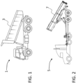
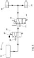
- FIG. 1 illustrates a tipper vehicle 1 according to one example, for which the teachings of this disclosure may be implemented.
- the tipper vehicle 1 in FIG. 1 is in the form of a rigid tipper truck.
- the tipper truck comprises a tipper body 3 from which material may be dispensed.
- the tipper body 3 is here illustrated in its tipped position.
- FIG. 2 illustrates a tipper vehicle 5 according to another example, for which the teachings of this disclosure may be implemented.
- the tipper vehicle 5 is here illustrated in the form of a trailer tipper. In this cases it is the trailer part of the vehicle 5 combination that is provided with a tipper body 7. Also in this case, the tipper body 7 is illustrated in its tipped position.
- FIG. 3 illustrates very schematically a parking brake system 10 of a tipper vehicle according to at least one example of this disclosure.
- FIG. 3 is very schematic and is included to provide a simple overview of some components that may be included in a parking brake system 10 according to at least one example of this disclosure.
- FIG. 3 illustrates an example of a parking brake system 10 that may be used in a tipper vehicle having a tipper body from which material is dispensable by tipping the tipper body.
- the parking brake system 10 comprises a parking brake which comprises a brake chamber 12 which is pressurizable for releasing the parking brake.
- the parking brake system 10 also comprises a valve device 14.
- the valve device 14 is in fluid communication with the brake chamber 12. Thus, air may flow between the brake chamber 12 and the valve device 14.
- the valve device 14 comprises an exhaust port 16.
- the valve device 14 has an activated state in which the brake chamber 12 is in fluid communication with the exhaust port 16, whereby air from the brake chamber 12 is discharged.
- the brake chamber 12 contains pressurized air (which is normally the case when the parking brake has been released)
- the pressure difference between the brake chamber 12 and the exhaust port 16 being normally at atmospheric pressure
- compressed air in the brake chamber 12 will pass through the valve device 14 and exit through the exhaust port 16.
- the valve device 14 also has an inactivated state in which the fluid communication between the exhaust port 16 and the brake chamber 12 is disconnected.
- FIG. 3 also illustrates schematically that the parking brake system 10 comprises four input devices 20, 22, 24, 26.
- a tipping detecting device 20 is configured to send a tipping signal 21 to the valve device 14.
- the tipping signal 21 is indicative of the tipper body being lifted.
- the tipping detecting device 20 may comprise a limit switch. In such case, when the tipper body is lifted the limit switch becomes closed and the tipping signal 21 is sent to the valve device 14.
- a neutral gear detecting device 22 is configured to send a neutral gear signal 23 to the valve device 14.
- the neutral gear signal 23 is indicative of the vehicle gear being in neutral.
- the neutral gear detecting device 22 may comprise a gear switch.
- a speed sensing device 24 is configured to send a low speed signal 25 to the valve device 14.
- the low speed signal 25 is indicative of the vehicle speed being zero or below a predefined threshold speed.
- the threshold speed is suitably set at a level which is below a normal speed of the vehicle that might be used in situations when you want to spread dumped material over a larger area and therefore purposively drive the vehicle forwardly.
- the speed sensing device 24 may comprise a speed sensor switch. In such case, when the vehicle speed is zero or below the predefined threshold speed, the speed sensor switch becomes closed and the low speed signal 25 is sent to the valve device 14.
- a parking brake detecting device 26 is configured to send a parking brake signal 27 to the valve device 14.
- the valve device 14 is configured to detect whether the parking brake is in a released state of has been activated by an operator so that it is in an applied state.
- the parking brake detecting device 26 may comprise a parking brake switch. In such case, when the parking brake is activated by an operator so that the parking brake becomes applied, then the parking brake switch may become opened so that the parking brake signal 27 is disconnected from the valve device 14.
- the valve device 14 Upon receipt of the tipping signal 21, the neutral gear signal 23 and the low speed signal 25, and upon detecting that the parking brake is still in the released state (in this example corresponding to the absence of the parking brake signal 27), the valve device 14 is changed from the inactivated state to the activated state in order to exhaust air from the brake chamber 12, thereby causing the parking brake to become changed to the applied state.
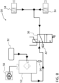
- FIGS. 4-6 illustrates schematically different states of some components in a parking brake system 30 of a tipper vehicle, in accordance with at least one example of this disclosure.
- a pressurized air source 32 such as a pressurized tank containing compressed air.
- the tank may, for example, become pressurized by means of an air compressor (not illustrated).
- the pressurized air source 32 may in some examples be considered to form part of the parking brake system 30 of this disclosure. In other examples, the pressurized air source 32 may be considered as not forming part of the parking brake system 30 of this disclosure, and instead forms a separate part to which the parking brake system 30 may be connected.
- the parking brake system 30 comprises a valve device, which may be referred to as a first valve device 36.
- FIG. 4 also illustrates that, in this example, the parking brake system 30 further comprises a second valve device 38.
- the second valve device 38 may be operatively connected to an operator-controlled device which enables an operator (such as a driver) to switch between an inactivated state and an activated state of the second valve device 38.
- the operator-controlled device may be a lever 40.
- the second valve device 38 is indeed illustrated as comprising a lever-operated hand brake valve. When the driver moves the lever 40 from a first position to a second position (usually by pulling the lever) the second valve device 38 changes from its inactivated state to its activated state. In FIG. 4 , the second valve device 38 is in its inactivated state.
- first valve device 36 When the first valve device 36 is in the inactivated state it allows fluid communication between the second valve device 38 and the brake chambers 34. Furthermore, when the second valve device 38 is in the inactivated state, then pressurized air from the pressurized air source 32 is allowed to pass through the second valve device 38 to the first valve device 36. Since FIG. 4 illustrates a case in which both the first valve device 36 and the second valve device 38 are in their respective inactivated state, pressurized air is allowed to flow from the pressurized air source 32 through the second valve device 38 and then through the first valve device 36, and then into the brake chambers 34 pressurizing them so as to hold the parking brake in a released state.
- the second valve device 38 is still in its inactivated state.
- the first valve device 36 has now been moved to its activated state.
- pressurized air can still pass from the pressurized air source 32 and through the second valve device 38, it will no longer be allowed to continue through the first valve device 36.
- the brake chambers 34 are in fluid communication with an exhaust port 42 of the first valve device 36, thereby allowing the pressurized air in the brake chambers 34 to be released through the exhaust port 42 of the first valve device.
- the exhaust port 42 of the first valve device 36 may be referred to as a first exhaust port 42.
- FIG. 6 it is instead the first valve device 36 that is in its inactivated state.
- the second valve device 38 has now moved to its activated state. Pressurized air can no longer pass from the pressurized air source 32 and through the second valve device 38. Instead, now the pressurized air in the brake chambers 34 are allowed to be exhausted by passing through the first valve device 36 to the second valve device 38 and then out to the ambient via an exhaust port 44 of the second valve device 38, thereby allowing the pressurized air in the brake chambers 34 to be released through the exhaust port 44 of the second valve device 38.
- the exhaust port 44 of the second valve device 38 may be referred to as a second exhaust port 44.
- FIG. 4 may represent a normal driving situation in which the parking brake is not engaged.
- the pressurized air source 32 is in fluid communication with the brake chambers 34 via the second valve device 38 and the first valve device 36, thereby pressurizing the brake chambers 34 and maintaining the parking brake in a released state.
- FIG. 6 represents a normal operator-initiated engagement of the parking brake. The driver has remembered to pull the lever 40, thus activating the second valve device 38, wherein pressurized air from the brake chambers 34 is exhausted through the second exhaust port 44, thereby engaging the parking brake.
- the first valve device 36 is in the inactivated state, thereby allowing the applying/releasing of the parking brake to be controlled by controlling the state of the second valve device 38.
- FIG. 5 illustrates the extra level of safety provided by the parking brake system of this disclosure.
- the operator has forgotten to engage the parking brake, i.e. has not activated the second valve device 38.
- the first valve device 36 has, however, received the tipping signal, the neutral gear signal and the low speed signal and has detected that the parking brake is still in the released state, and therefore moved to the activated state, whereby the pressurized air in the chambers 34 are exhausted through the first exhaust port 42 to engage the parking brake.
- the first valve device 36 is illustrated as comprising a solenoid valve that may be energized. When the first valve device 36 is not energized then it is biased towards the inactivated state of the first valve device 36. As mentioned previously, FIG. 4 illustrates the first valve device 36 in the inactivated state. The biasing towards the inactivated state may, for instance, be achieved by a spring device 46. When the first valve device 36 becomes energized, the first valve device 36 moves against the force of the spring device 46 to the activated state.
- FIG. 5 illustrates the activated state of the first valve device 36, i.e. when the first valve device 36 has become energized.
- the energization of the first valve device 36 is dependent on the previously discussed reception of signals and determination of state of the parking brake.
- the first valve device 36 in FIG. 4 becomes energized upon receipt of the tipping signal, the neutral gear signal and the low speed signal in combination with detecting that the parking brake is still in the released state (e.g. in case of a parking switch, the switch is closed when parking brake is released, allowing the parking brake signal to reach the first valve device 36).
- the first valve device 36 may be energized by an energization signal triggered by the receipt of the tipping signal, the neutral gear signal and the low speed signal, in combination with the detecting that the parking brake is still in the released state.
- an energization signal triggered by the receipt of the tipping signal, the neutral gear signal and the low speed signal, in combination with the detecting that the parking brake is still in the released state.
- the operator-controlled device here in the form of the lever 40
- any triggering of the energization signal is blocked, thereby avoiding energization of the solenoid valve of the first valve device 36.
- unnecessary and superfluous energization and movement of first valve device 36 can be avoided, and thus the wear and tear of the first valve device 36 can be reduced, while providing an additional level of safety to the handling of the tipper vehicle.
- FIGS. 7-9 illustrates schematically different states of some components in a parking brake system 50 of a tipper vehicle, in accordance with at least another example of this disclosure. While the previous example in FIGS. 4-6 illustrates a second valve device 38 which comprises a lever-operated hand brake valve, the example in FIGS. 7-9 instead illustrates a second valve device 52 which comprises an electronically controlled valve. The general principle is, however, similar. Thus, FIG. 7 illustrates a case in which both the first valve device 36 and the second valve device 52 are in their respective inactivated state, wherein pressurized air is allowed to flow from the pressurized air source 32 through the second valve device 52 and then through the first valve device 36 and then into the brake chambers 34 so as to hold the parking brake in a released state.
- FIG. 7 may represent a normal driving situation.
- the second valve device 52 is still in its inactivated state.
- the first valve device 36 has now moved to its activated state.
- pressurized air can still pass from the pressurized air source 32 through the second valve device 52, it will no longer be allowed to continue through the first valve device 36.
- the brake chambers 34 are in fluid communication with the first exhaust port 42, i.e. the exhaust port 42 of the first valve device 36, thereby allowing the pressurized air in the brake chambers 34 to be released through the first exhaust port 42.
- FIG. 8 may represent a situation in which the operator has forgotten to engage the parking brake and has initiated a stationary tipping operation.
- the first valve device 36 has therefore, based on the lack of parking brake engagement, and the received tipping signal, neutral gear signal and low speed signal now automatically moved to its activated state, whereby the parking brake has become engaged.
- the first valve device 36 is in its inactivated state while the second valve device 52 has moved to its activated state. Pressurized air can no longer pass from the pressurized air source 32 and through the second valve device 52. Instead, now the pressurized air in the brake chambers 34 are allowed to be exhausted by passing through the first valve device 36 to the second valve device 52 and then out to the ambient via the second exhaust port 54, i.e. the exhaust port 54 of the second valve device 52, thereby allowing the pressurized air in the brake chambers 34 to be released through the second exhaust port 54.
- FIG. 9 may represent a normal operator-initiated engagement of the parking brake.
- the operator/driver may trigger the activation of the second valve device 52 and hence the engagement of the parking brake by actuation of an electronic parking switch 56.
- the actuation of the electronic parking switch 56 triggers an electrical signal 58 which is sent to the second valve device 52.
- the first valve device 36 may be omitted and its functionality may instead be integrated into the electronically controlled second valve device 52 by appropriate reprogramming of the logic in the second valve device 52.
- the second valve device 52 may, in such case, be configured to receive the tipping signal, the neutral gear signal and the low speed signal, and be configured to detect that the parking brake has not been engaged by an operator-initiated engagement (i.e. the electronic parking switch 56 has not been actuated and for example no electrical signal 58 from the electronic parking switch 56 has been received), and based on the these factors, the second valve device 52 may automatically change to its activated state, thereby causing the parking brake to become engaged.
- FIG. 10 illustrates schematically a method of applying a parking brake of a tipper vehicle, in accordance with at least one example of this disclosure. More specifically, FIG. 10 illustrates a method 100 of applying a parking brake of a tipper vehicle having a tipper body from which carried material is dispensable by tipping the tipper body, the method 100 comprising:
- Relative terms such as “below” or “above” or “upper” or “lower” or “horizontal” or “vertical” may be used herein to describe a relationship of one element to another element as illustrated in the Figures. It will be understood that these terms and those discussed above are intended to encompass different orientations of the device in addition to the orientation depicted in the Figures. It will be understood that when an element is referred to as being “connected” or “coupled” to another element, it can be directly connected or coupled to the other element, or intervening elements may be present. In contrast, when an element is referred to as being “directly connected” or “directly coupled” to another element, there are no intervening elements present.
Landscapes
- Engineering & Computer Science (AREA)
- Transportation (AREA)
- Mechanical Engineering (AREA)
- Regulating Braking Force (AREA)
Abstract
Description
- The disclosure relates generally to a parking brake system. In particular aspects, the disclosure relates to a parking brake system of a tipper vehicle. The disclosure can be applied in heavy-duty vehicles, such as rigid tipper trucks and trailer tippers. Although the disclosure may be described with respect to a particular vehicle, the disclosure is not restricted to any particular vehicle.
- A tipper truck, also known as a dump truck or dumper truck, is used for transporting materials, usually for construction. Tipper trucks have a tipper body in which material may be transported. The material is dumped from the tipper truck by tipping/tilting the tipper body. During tipping, it is recommended that the parking brake is engaged. If the parking brake is not engaged, there is a risk that the vehicle will move forward or roll when unloading the material. However, due to human error a driver may forget to apply the parking brake which may lead to an accident or create an unsafe environment. Thus, there is room for improvement when it comes to safety measures in relation to tipper trucks.
- According to a first aspect of the disclosure, there is provided a parking brake system of a tipper vehicle having a tipper body from which carried material is dispensable by tipping the tipper body, the parking brake system comprising:
- a parking brake which comprises a brake chamber which is pressurizable for releasing the parking brake,
- a valve device in fluid communication with the brake chamber, the valve device comprising an exhaust port, wherein the valve device has an activated state in which the brake chamber is in fluid communication with the exhaust port whereby air from the brake chamber is discharged, thereby applying the parking brake, and an inactivated state in which the fluid communication between the exhaust port and the brake chamber is disconnected,
- a tipping detecting device configured to send a tipping signal to the valve device, the tipping signal being indicative of the tipper body being lifted,
- a neutral gear detecting device configured to send a neutral gear signal to the valve device, the neutral gear signal being indicative of the vehicle gear being in neutral,
- a speed sensing device configured to send a low speed signal to the valve device, the low speed signal being indicative of the vehicle speed being zero or below a predefined threshold speed,
- a parking brake detecting device configured to send a parking brake signal to the valve device, wherein, by detecting the presence or absence of the parking brake signal, the valve device is configured to detect whether the parking brake is in a released state or has been activated by an operator so that it is in an applied state,
- It should be understood that the general teachings of this disclosure may be implemented for parking brakes of manual handbrakes (such as lever type hand brakes) as well as for electronic parking brake switches. It should also be understood that electronics of the parking brake detecting device may be configured in various different ways. For instance, in some examples, the parking brake detecting device may be designed such that the parking brake signal is sent to the valve device when the parking brake is in its applied state. In such cases, detecting the absence of the parking brake signal may cause the valve device to detect that the parking brake is in its released state. Conversely, in other examples, the parking brake detecting device may be designed such that the parking brake signal is sent when the parking brake is in its released state. In such cases, detecting the presence of the parking brake signal may cause the valve device to detect that the parking brake is in its released state.
- The tipping signal, the neutral gear signal, the low speed signal and the parking brake signal may, for example, be implemented as simple voltage signals. For instance, a voltage of 12 V or 24 V represents signal ON, while 0 V represents signal OFF.
- In some examples, said valve device is a first valve device and said exhaust port is a first exhaust port, the parking brake system further comprising:
- a second valve device comprising a second exhaust port,
- wherein when the first valve device is in the inactivated state it allows fluid communication between the second valve device and the brake chamber,
- wherein the second valve device has an activated state and an inactivated stated,
- wherein when the first valve device is in its inactivated state and the second valve device is in the activated state, then the brake chamber is in fluid communication with the second exhaust port, whereby air from the brake chamber is discharged, thereby applying the parking brake,
- wherein when the second valve device is in the inactivated state, then pressurized air from a pressurized air source is allowed to pass through the second valve device to the first valve device.
- In some examples, the parking brake system further comprises an operator-controlled device which is operatively connected to the second valve device, thereby enabling an operator to switch between the activated state and the inactivated state of the second valve device. As mentioned above, a technical benefit may include that the second valve device may be used for normal driver-initiated engagement of the parking brake, while the first valve device may function as a back-up in case the driver has omitted to engage the parking brake. The operator-controlled device may in some examples be an electronic parking switch. The operator-controlled device may be thus, in some examples, be configured to send an electrical signal to the second valve device to change from the inactivated state to the activated state of the second valve device, or vice versa. In some examples, the operator-controlled device may include or be in the form of a hand brake lever. Thus, in some examples the operator-controlled device may be configured to mechanically move the second valve device from its inactivated state to its activated state, or vice versa.
- In some examples, unless it is indicated to the first valve device that the tipper body is being lifted, as well as the vehicle gear is in neutral, as well as the vehicle speed being zero or below a predefined threshold, then the first valve is in the inactivated state, thereby allowing the applying/releasing of the parking brake to be controlled by controlling the state of the second valve device. A technical benefit may include that normal operation of the parking brake is allowed if the first valve device gets indication that the vehicle is not presently in the process of performing a stationary tipping operation. For instance, in some cases, a driver may wish to spread the material over a larger area on the ground and may therefore drive the vehicle forward simultaneously with dispensing material form the tilted tipping body. In such case, although the tipper body has been lifted, it will be detected that the vehicle gear is not in neutral, and that the vehicle is driving at a certain speed. Thus, in such case the first valve device will remain in the inactivated state to avoid unwanted engagement of the parking brake. Furthermore, when the driver switches gears, for example, from third gear to fourth gear, via neutral gear, even though the gear will temporarily be in neutral during such gear switch, the valve device will remain in the inactivated state (assuming the speed of the vehicle is above the predefined threshold speed). Thus, a technical benefit of requiring both the neutral gear signal and the low speed signal to be detected, is that there is no risk that the parking brake will inadvertently be engaged when vehicle is driving at high speed during a gear switch. Purely as an illustrative example, the predefined threshold speed may be a value in the range of 10-15 km/h. Engaging the parking brake for a truck driving at 15 km/h does normally not cause any discomfort to the driver.
- In some examples, the first valve device comprises a solenoid valve which is biased towards the inactivated state when it is not energized, wherein upon receipt of said tipping signal, said neutral gear signal and said low speed signal, and upon detecting that the parking brake is still in the released state, the valve device becomes energized to change from the inactivated state to the activated state. A technical benefit may include that a solenoid valve device is conveniently controllable by electric input signals.
- In some examples, the solenoid valve is energized by an energization signal triggered by the receipt of said tipping signal, said neutral gear signal and said low speed signal, and the detecting that the parking brake is still in the released state, wherein when the operator-controlled device has switched the second valve device to the activated state to apply the parking brake, then any triggering of the energization signal is blocked, thereby avoiding energization of the solenoid valve. Similarly to the above discussions, a technical benefit may include that the solenoid valve will not be worn out prematurely. By including the state of the parking brake as a parameter for triggering the energization signal, superfluous energization and movement of the solenoid valve can be avoided.
- In some examples, the second valve device comprise an electronically controlled valve, wherein the second valve device is switched to the activated state by an electrical signal triggered by actuation of an electronic parking switch. In some examples, the second valve device comprises a lever-operated hand brake valve, wherein moving the lever between a first position and a second position causes the second valve to change from its inactivated state to its activated state. Thus, the teachings of the present disclosure may be implemented for different operator-controlled devices.
- In some examples, the parking brake system further comprises a limit switch provided at the chassis, the limit switch forming part of the tipping detecting device, wherein when the tipper body is lifted the limit switch becomes closed and the tipping signal is sent to the valve device. A technical benefit may include that a limit switch provides a reliable and convenient way to detect that the tipping body is lifted. When the tipper body is lowered back to its original position, thereby opening the switch, the tipping signal is no longer sent to the valve device, and the parking brake may be released. This logic is not limited to a limit switch, but may be implemented for other types of tipping detecting devices, i.e. when tipping signal is no longer received by the valve device, the valve device may be changed back to the inactivated state. Similarly, if the driver sets the gear in drive mode (i.e. neutral gear signal is no longer received), for example in order to distribute the carried load over a larger area, then the valve device will be changed back to the inactivated state.
- In some examples, the parking brake system further comprises a speed sensor switch forming part of the speed sensing device, wherein when the vehicle speed is zero or below the predefined threshold speed the speed sensor switch becomes closed and the low speed signal is sent to the valve device. A technical benefit may include that a speed sensor switch presents an effective way to provide said low speed signal.
- In some examples, the parking brake system further comprises a gear switch forming part of the neutral gear detecting device, wherein when the vehicle gear is in neutral state, the gear switch becomes closed and the neutral gear signal is sent to the valve device. A technical benefit may include that a gear switch presents an effective way to provide said neutral gear signal.
- In some examples, the parking brake system further comprises a parking brake switch forming part of the parking brake detecting device, wherein when the parking brake is activated by an operator so that the parking brake becomes applied, then the parking brake switch becomes opened and the parking brake signal is disconnected from the valve device. Thus, by using a switch which opens when the parking brake is activated by an operator and effective way to disconnect the parking brake signal from the valve device is achieved. Hereby, in case of the valve device being in the form of said first valve device, it will not be activated superfluously if the second valve device has already been activated to engage the parking brake.
- Providing a first valve device as a back-up and a second valve device for normal driver-initiated parking braking may be advantageous as previously discussed. Nevertheless, in some examples, it may be conceivable to use only one valve device for the parking brake system. In particular, in some examples, the valve device may comprise an electronically controlled valve operated by an electrical parking switch. The electronically controlled valve can be programmed to become activated if the driver has omitted to engage the parking brake and the electronically controlled valve has received the tipping signal, neutral gear signal and low speed signal.
- According to a second aspect of the disclosure, there is provided a tipper truck vehicle comprising the parking brake system of the first aspect, including any example thereof. Technical benefits of the second aspect may largely correspond to those of the first aspect, including any examples thereof.
- In some examples, the tipper vehicle is a tipper truck or a tractor trailer tipper truck. Thus, the teachings of this disclosure may advantageously be implemented for different types of tipper vehicles, and is not restricted to a particular type of tipper vehicle.
- According to a third aspect of the disclosure, there is provided a method of applying a parking brake of a tipper vehicle having a tipper body from which carried material is dispensable by tipping the tipper body, the method comprising:
- receiving, by a valve device, a tipping signal indicative of the tipper body being lifted,
- receiving, by the valve device, a neutral gear signal indicative of the vehicle gear being in neutral,
- receiving, by the valve device, a low speed signal indicative of the vehicle speed being zero or below a predefined threshold speed,
- detecting, by the valve device, the presence or absence of a parking brake signal, thereby detecting, by the valve device, whether the parking brake is in the released state or has been activated by an operator so that it is in an applied state, and
- upon receipt of said tipping signal, said neutral gear signal and said low speed signal, and upon detecting that the parking brake is in the released state, fluidly connecting, by the valve device, a brake chamber of the parking brake to an exhaust port of the valve device, thereby discharging air from the brake chamber to the exhaust port, causing the parking brake to be changed to the applied state.
- In some examples of the method of the third aspect, said valve device is the valve device of the parking brake system of the first aspect, including any examples thereof.
- The above aspects, accompanying claims, and/or examples disclosed herein above and later below may be suitably combined with each other as would be apparent to anyone of ordinary skill in the art.
- Additional features and advantages are disclosed in the following description, claims, and drawings, and in part will be readily apparent therefrom to those skilled in the art or recognized by practicing the disclosure as described herein. There are also disclosed herein control units, computer readable media, and computer program products associated with the above discussed technical benefits.
- With reference to the appended drawings, below follows a more detailed description of aspects of the disclosure cited as examples.
-
FIG. 1 illustrates a tipper vehicle according to one example, for which the teachings of this disclosure may be implemented. -
FIG. 2 illustrates a tipper vehicle according to another example, for which the teachings of this disclosure may be implemented. -
FIG. 3 illustrates very schematically a parking brake system of a tipper vehicle according to at least one example of this disclosure. -
FIGS. 4-6 illustrates schematically different states of some components in a parking brake system of a tipper vehicle, in accordance with at least one example of this disclosure. -
FIGS. 7-9 illustrates schematically different states of some components in a parking brake system of a tipper vehicle, in accordance with at least another example of this disclosure. -
FIG. 10 illustrates schematically a method of applying a parking brake of a tipper vehicle, in accordance with at least one example of this disclosure. - Aspects set forth below represent the necessary information to enable those skilled in the art to practice the disclosure.
- When material is dispensed from a tipper truck by tipping/tilting the tipper body, accidents may occur if the parking brake is not engaged. Sometimes the driver may inadvertently forget to engage the parking brake, and therefore the vehicle may start to move forward or roll when unloading the material, which may lead to an accident. By taking certain parameters into account, the parking brake system of the present disclosure automatically engages the parking brake if the driver has forgotten to do so. Furthermore, the parking brake system of the present disclosure also provides the advantage of not over-actuating system components, and thus avoiding unnecessary and premature wear of system components.
-
FIG. 1 illustrates atipper vehicle 1 according to one example, for which the teachings of this disclosure may be implemented. Thetipper vehicle 1 inFIG. 1 is in the form of a rigid tipper truck. The tipper truck comprises a tipper body 3 from which material may be dispensed. The tipper body 3 is here illustrated in its tipped position. -
FIG. 2 illustrates atipper vehicle 5 according to another example, for which the teachings of this disclosure may be implemented. Thetipper vehicle 5 is here illustrated in the form of a trailer tipper. In this cases it is the trailer part of thevehicle 5 combination that is provided with a tipper body 7. Also in this case, the tipper body 7 is illustrated in its tipped position. - It should be understood that the different examples of a parking brake system that will be discussed in connection with
FIGS. 3-9 and which are also discussed elsewhere in this disclosure may be implemented for different types of tipping vehicles, including for thevehicles FIGS. 1 and 2 . -
FIG. 3 illustrates very schematically aparking brake system 10 of a tipper vehicle according to at least one example of this disclosure.FIG. 3 is very schematic and is included to provide a simple overview of some components that may be included in aparking brake system 10 according to at least one example of this disclosure. Thus,FIG. 3 illustrates an example of aparking brake system 10 that may be used in a tipper vehicle having a tipper body from which material is dispensable by tipping the tipper body. Theparking brake system 10 comprises a parking brake which comprises abrake chamber 12 which is pressurizable for releasing the parking brake. Theparking brake system 10 also comprises avalve device 14. Thevalve device 14 is in fluid communication with thebrake chamber 12. Thus, air may flow between thebrake chamber 12 and thevalve device 14. Thevalve device 14 comprises anexhaust port 16. Thevalve device 14 has an activated state in which thebrake chamber 12 is in fluid communication with theexhaust port 16, whereby air from thebrake chamber 12 is discharged. Thus, in the activated state of thevalve device 14, if thebrake chamber 12 contains pressurized air (which is normally the case when the parking brake has been released), then due to the pressure difference between thebrake chamber 12 and the exhaust port 16 (being normally at atmospheric pressure), compressed air in thebrake chamber 12 will pass through thevalve device 14 and exit through theexhaust port 16. Hereby, the parking brake becomes engaged. Thevalve device 14 also has an inactivated state in which the fluid communication between theexhaust port 16 and thebrake chamber 12 is disconnected. -
FIG. 3 also illustrates schematically that theparking brake system 10 comprises fourinput devices tipping detecting device 20 is configured to send atipping signal 21 to thevalve device 14. Thetipping signal 21 is indicative of the tipper body being lifted. As an example, thetipping detecting device 20 may comprise a limit switch. In such case, when the tipper body is lifted the limit switch becomes closed and thetipping signal 21 is sent to thevalve device 14. A neutralgear detecting device 22 is configured to send aneutral gear signal 23 to thevalve device 14. Theneutral gear signal 23 is indicative of the vehicle gear being in neutral. As an example, the neutralgear detecting device 22 may comprise a gear switch. In such case, when the vehicle gear is set in neutral state the gear switch becomes closed and theneutral gear signal 23 is sent to thevalve device 14. Aspeed sensing device 24 is configured to send alow speed signal 25 to thevalve device 14. Thelow speed signal 25 is indicative of the vehicle speed being zero or below a predefined threshold speed. The threshold speed is suitably set at a level which is below a normal speed of the vehicle that might be used in situations when you want to spread dumped material over a larger area and therefore purposively drive the vehicle forwardly. As an example, thespeed sensing device 24 may comprise a speed sensor switch. In such case, when the vehicle speed is zero or below the predefined threshold speed, the speed sensor switch becomes closed and thelow speed signal 25 is sent to thevalve device 14. A parkingbrake detecting device 26 is configured to send aparking brake signal 27 to thevalve device 14. By detecting the presence or absence of theparking brake signal 27, thevalve device 14 is configured to detect whether the parking brake is in a released state of has been activated by an operator so that it is in an applied state. As an example, the parkingbrake detecting device 26 may comprise a parking brake switch. In such case, when the parking brake is activated by an operator so that the parking brake becomes applied, then the parking brake switch may become opened so that theparking brake signal 27 is disconnected from thevalve device 14. - Upon receipt of the
tipping signal 21, theneutral gear signal 23 and thelow speed signal 25, and upon detecting that the parking brake is still in the released state (in this example corresponding to the absence of the parking brake signal 27), thevalve device 14 is changed from the inactivated state to the activated state in order to exhaust air from thebrake chamber 12, thereby causing the parking brake to become changed to the applied state. -
FIGS. 4-6 illustrates schematically different states of some components in aparking brake system 30 of a tipper vehicle, in accordance with at least one example of this disclosure. Starting withFIG. 4 , there is illustrated apressurized air source 32, such as a pressurized tank containing compressed air. The tank may, for example, become pressurized by means of an air compressor (not illustrated). Thepressurized air source 32 may in some examples be considered to form part of theparking brake system 30 of this disclosure. In other examples, thepressurized air source 32 may be considered as not forming part of theparking brake system 30 of this disclosure, and instead forms a separate part to which theparking brake system 30 may be connected. There are illustrated twobrake chambers 34, one for a left wheel and one for a right wheel, however there may be provided further parking brake chambers on a tipper vehicle, and theparking brake system 30 may thus, in at least some examples, include more than twobrake chambers 34. Theparking brake system 30 comprises a valve device, which may be referred to as afirst valve device 36. -
FIG. 4 also illustrates that, in this example, theparking brake system 30 further comprises asecond valve device 38. Thesecond valve device 38 may be operatively connected to an operator-controlled device which enables an operator (such as a driver) to switch between an inactivated state and an activated state of thesecond valve device 38. For instance, the operator-controlled device may be alever 40. InFIG. 4 , thesecond valve device 38 is indeed illustrated as comprising a lever-operated hand brake valve. When the driver moves thelever 40 from a first position to a second position (usually by pulling the lever) thesecond valve device 38 changes from its inactivated state to its activated state. InFIG. 4 , thesecond valve device 38 is in its inactivated state. - When the
first valve device 36 is in the inactivated state it allows fluid communication between thesecond valve device 38 and thebrake chambers 34. Furthermore, when thesecond valve device 38 is in the inactivated state, then pressurized air from thepressurized air source 32 is allowed to pass through thesecond valve device 38 to thefirst valve device 36. SinceFIG. 4 illustrates a case in which both thefirst valve device 36 and thesecond valve device 38 are in their respective inactivated state, pressurized air is allowed to flow from thepressurized air source 32 through thesecond valve device 38 and then through thefirst valve device 36, and then into thebrake chambers 34 pressurizing them so as to hold the parking brake in a released state. - In
FIG. 5 thesecond valve device 38 is still in its inactivated state. Thefirst valve device 36, however, has now been moved to its activated state. Although pressurized air can still pass from thepressurized air source 32 and through thesecond valve device 38, it will no longer be allowed to continue through thefirst valve device 36. Instead, now thebrake chambers 34 are in fluid communication with anexhaust port 42 of thefirst valve device 36, thereby allowing the pressurized air in thebrake chambers 34 to be released through theexhaust port 42 of the first valve device. Theexhaust port 42 of thefirst valve device 36 may be referred to as afirst exhaust port 42. - In
FIG. 6 it is instead thefirst valve device 36 that is in its inactivated state. Now, however, thesecond valve device 38, has now moved to its activated state. Pressurized air can no longer pass from thepressurized air source 32 and through thesecond valve device 38. Instead, now the pressurized air in thebrake chambers 34 are allowed to be exhausted by passing through thefirst valve device 36 to thesecond valve device 38 and then out to the ambient via anexhaust port 44 of thesecond valve device 38, thereby allowing the pressurized air in thebrake chambers 34 to be released through theexhaust port 44 of thesecond valve device 38. Theexhaust port 44 of thesecond valve device 38 may be referred to as asecond exhaust port 44. - Thus, from the above explanation of
FIGS. 4-6 , it should now be understood thatFIG. 4 may represent a normal driving situation in which the parking brake is not engaged. Thepressurized air source 32 is in fluid communication with thebrake chambers 34 via thesecond valve device 38 and thefirst valve device 36, thereby pressurizing thebrake chambers 34 and maintaining the parking brake in a released state.FIG. 6 represents a normal operator-initiated engagement of the parking brake. The driver has remembered to pull thelever 40, thus activating thesecond valve device 38, wherein pressurized air from thebrake chambers 34 is exhausted through thesecond exhaust port 44, thereby engaging the parking brake. Thus, unless it is indicated to thefirst valve device 36 that the parking brake is in released state and that the tipper body is being lifted, as well as the vehicle gear is in neutral, as well as the vehicle speed being zero or below a predefined threshold, then thefirst valve device 36 is in the inactivated state, thereby allowing the applying/releasing of the parking brake to be controlled by controlling the state of thesecond valve device 38. -
FIG. 5 , however, illustrates the extra level of safety provided by the parking brake system of this disclosure. The operator has forgotten to engage the parking brake, i.e. has not activated thesecond valve device 38. Thefirst valve device 36 has, however, received the tipping signal, the neutral gear signal and the low speed signal and has detected that the parking brake is still in the released state, and therefore moved to the activated state, whereby the pressurized air in thechambers 34 are exhausted through thefirst exhaust port 42 to engage the parking brake. - In
FIGS. 4-6 , thefirst valve device 36 is illustrated as comprising a solenoid valve that may be energized. When thefirst valve device 36 is not energized then it is biased towards the inactivated state of thefirst valve device 36. As mentioned previously,FIG. 4 illustrates thefirst valve device 36 in the inactivated state. The biasing towards the inactivated state may, for instance, be achieved by aspring device 46. When thefirst valve device 36 becomes energized, thefirst valve device 36 moves against the force of thespring device 46 to the activated state.FIG. 5 illustrates the activated state of thefirst valve device 36, i.e. when thefirst valve device 36 has become energized. The energization of thefirst valve device 36 is dependent on the previously discussed reception of signals and determination of state of the parking brake. Thus, analogously with what has previously been discussed in relation toFIG. 3 , thefirst valve device 36 inFIG. 4 becomes energized upon receipt of the tipping signal, the neutral gear signal and the low speed signal in combination with detecting that the parking brake is still in the released state (e.g. in case of a parking switch, the switch is closed when parking brake is released, allowing the parking brake signal to reach the first valve device 36). - The
first valve device 36 may be energized by an energization signal triggered by the receipt of the tipping signal, the neutral gear signal and the low speed signal, in combination with the detecting that the parking brake is still in the released state. When the operator-controlled device (here in the form of the lever 40) has switched thesecond valve device 38 to the activated state to apply the parking brake (as inFIG. 6 ), then any triggering of the energization signal is blocked, thereby avoiding energization of the solenoid valve of thefirst valve device 36. Hereby, unnecessary and superfluous energization and movement offirst valve device 36 can be avoided, and thus the wear and tear of thefirst valve device 36 can be reduced, while providing an additional level of safety to the handling of the tipper vehicle. -
FIGS. 7-9 illustrates schematically different states of some components in aparking brake system 50 of a tipper vehicle, in accordance with at least another example of this disclosure. While the previous example inFIGS. 4-6 illustrates asecond valve device 38 which comprises a lever-operated hand brake valve, the example inFIGS. 7-9 instead illustrates asecond valve device 52 which comprises an electronically controlled valve. The general principle is, however, similar. Thus,FIG. 7 illustrates a case in which both thefirst valve device 36 and thesecond valve device 52 are in their respective inactivated state, wherein pressurized air is allowed to flow from thepressurized air source 32 through thesecond valve device 52 and then through thefirst valve device 36 and then into thebrake chambers 34 so as to hold the parking brake in a released state. Thus,FIG. 7 may represent a normal driving situation. InFIG. 8 thesecond valve device 52 is still in its inactivated state. Thefirst valve device 36, however, has now moved to its activated state. Although pressurized air can still pass from thepressurized air source 32 through thesecond valve device 52, it will no longer be allowed to continue through thefirst valve device 36. Instead, now thebrake chambers 34 are in fluid communication with thefirst exhaust port 42, i.e. theexhaust port 42 of thefirst valve device 36, thereby allowing the pressurized air in thebrake chambers 34 to be released through thefirst exhaust port 42. Thus,FIG. 8 may represent a situation in which the operator has forgotten to engage the parking brake and has initiated a stationary tipping operation. Thefirst valve device 36 has therefore, based on the lack of parking brake engagement, and the received tipping signal, neutral gear signal and low speed signal now automatically moved to its activated state, whereby the parking brake has become engaged. InFIG. 9 thefirst valve device 36 is in its inactivated state while thesecond valve device 52 has moved to its activated state. Pressurized air can no longer pass from thepressurized air source 32 and through thesecond valve device 52. Instead, now the pressurized air in thebrake chambers 34 are allowed to be exhausted by passing through thefirst valve device 36 to thesecond valve device 52 and then out to the ambient via thesecond exhaust port 54, i.e. theexhaust port 54 of thesecond valve device 52, thereby allowing the pressurized air in thebrake chambers 34 to be released through thesecond exhaust port 54. Thus,FIG. 9 may represent a normal operator-initiated engagement of the parking brake. - In the example of
FIGS. 7-9 , the operator/driver may trigger the activation of thesecond valve device 52 and hence the engagement of the parking brake by actuation of anelectronic parking switch 56. The actuation of theelectronic parking switch 56 triggers anelectrical signal 58 which is sent to thesecond valve device 52. - In a further example (not illustrated), the
first valve device 36 may be omitted and its functionality may instead be integrated into the electronically controlledsecond valve device 52 by appropriate reprogramming of the logic in thesecond valve device 52. Thus, thesecond valve device 52 may, in such case, be configured to receive the tipping signal, the neutral gear signal and the low speed signal, and be configured to detect that the parking brake has not been engaged by an operator-initiated engagement (i.e. theelectronic parking switch 56 has not been actuated and for example noelectrical signal 58 from theelectronic parking switch 56 has been received), and based on the these factors, thesecond valve device 52 may automatically change to its activated state, thereby causing the parking brake to become engaged. -
FIG. 10 illustrates schematically a method of applying a parking brake of a tipper vehicle, in accordance with at least one example of this disclosure. More specifically,FIG. 10 illustrates amethod 100 of applying a parking brake of a tipper vehicle having a tipper body from which carried material is dispensable by tipping the tipper body, themethod 100 comprising: - in a
step S 1, receiving, by a valve device, a tipping signal indicative of the tipper body being lifted, - in a step S2, receiving, by the valve device, a neutral gear signal indicative of the vehicle gear being in neutral,
- in a step S3, receiving, by the valve device, a low speed signal indicative of the vehicle speed being zero or below a predefined threshold speed,
- in a step S4, detecting, by the valve device, the presence or absence of a parking brake signal, thereby detecting, by the valve device, whether the parking brake is in the released state or has been activated by an operator so that it is in an applied state, and
- in a step S5, upon receipt of said tipping signal, said neutral gear signal and said low speed signal, and upon detecting that the parking brake is in the released state, fluidly connecting, by the valve device, a brake chamber of the parking brake to an exhaust port of the valve device, thereby discharging air from the brake chamber to the exhaust port, causing the parking brake to be changed to the applied state.
- The terminology used herein is for the purpose of describing particular aspects only and is not intended to be limiting of the disclosure. As used herein, the singular forms "a," "an," and "the" are intended to include the plural forms as well, unless the context clearly indicates otherwise. As used herein, the term "and/or" includes any and all combinations of one or more of the associated listed items. It will be further understood that the terms "comprises," "comprising," "includes," and/or "including" when used herein specify the presence of stated features, integers, steps, operations, elements, and/or components, but do not preclude the presence or addition of one or more other features, integers, steps, operations, elements, components, and/or groups thereof.
- It will be understood that, although the terms first, second, etc., may be used herein to describe various elements, these elements should not be limited by these terms. These terms are only used to distinguish one element from another. For example, a first element could be termed a second element, and, similarly, a second element could be termed a first element without departing from the scope of the present disclosure.
- Relative terms such as "below" or "above" or "upper" or "lower" or "horizontal" or "vertical" may be used herein to describe a relationship of one element to another element as illustrated in the Figures. It will be understood that these terms and those discussed above are intended to encompass different orientations of the device in addition to the orientation depicted in the Figures. It will be understood that when an element is referred to as being "connected" or "coupled" to another element, it can be directly connected or coupled to the other element, or intervening elements may be present. In contrast, when an element is referred to as being "directly connected" or "directly coupled" to another element, there are no intervening elements present.
- Unless otherwise defined, all terms (including technical and scientific terms) used herein have the same meaning as commonly understood by one of ordinary skill in the art to which this disclosure belongs. It will be further understood that terms used herein should be interpreted as having a meaning consistent with their meaning in the context of this specification and the relevant art and will not be interpreted in an idealized or overly formal sense unless expressly so defined herein.
- It is to be understood that the present disclosure is not limited to the aspects described above and illustrated in the drawings; rather, the skilled person will recognize that many changes and modifications may be made within the scope of the present disclosure and appended claims. In the drawings and specification, there have been disclosed aspects for purposes of illustration only and not for purposes of limitation, the scope of the inventive concepts being set forth in the following claims.
Claims (16)
- A parking brake system of a tipper vehicle having a tipper body from which carried material is dispensable by tipping the tipper body, the parking brake system comprising:- a parking brake which comprises a brake chamber which is pressurizable for releasing the parking brake,- a valve device in fluid communication with the brake chamber, the valve device comprising an exhaust port, wherein the valve device has an activated state in which the brake chamber is in fluid communication with the exhaust port whereby air from the brake chamber is discharged, thereby applying the parking brake, and an inactivated state in which the fluid communication between the exhaust port and the brake chamber is disconnected,- a tipping detecting device configured to send a tipping signal to the valve device, the tipping signal being indicative of the tipper body being lifted,- a neutral gear detecting device configured to send a neutral gear signal to the valve device, the neutral gear signal being indicative of the vehicle gear being in neutral,- a speed sensing device configured to send a low speed signal to the valve device, the low speed signal being indicative of the vehicle speed being zero or below a predefined threshold speed,- a parking brake detecting device configured to send a parking brake signal to the valve device, wherein, by detecting the presence or absence of the parking brake signal, the valve device is configured to detect whether the parking brake is in a released state or has been activated by an operator so that it is in an applied state,wherein upon receipt of said tipping signal, said neutral gear signal and said low speed signal, and upon detecting that the parking brake is still in the released state, the valve device is changed from the inactivated state to the activated state in order to exhaust air from the brake chamber, thereby causing the parking brake to become changed to the applied state.
- The parking brake system of claim 1, wherein said valve device is a first valve device and said exhaust port is a first exhaust port, the parking brake system further comprising:- a second valve device comprising a second exhaust port,wherein when the first valve device is in the inactivated state it allows fluid communication between the second valve device and the brake chamber,wherein the second valve device has an activated state and an inactivated stated, wherein when the first valve device is in its inactivated state and the second valve device is in the activated state, then the brake chamber is in fluid communication with the second exhaust port, whereby air from the brake chamber is discharged, thereby applying the parking brake,wherein when the second valve device is in the inactivated state, then pressurized air from a pressurized air source is allowed to pass through the second valve device to first valve device.
- The parking brake system of claim 2, further comprising an operator-controlled device which is operatively connected to the second valve device, thereby enabling an operator to switch between the activated state and the inactivated state of the second valve device.
- The parking brake system of any of claims 2-3, wherein unless it is indicated to the first valve device that the tipper body is being lifted, as well as the vehicle gear is in neutral, as well as the vehicle speed being zero or below a predefined threshold, then the first valve is in the inactivated state, thereby allowing the applying/releasing of the parking brake to be controlled by controlling the state of the second valve device.
- The parking brake system of any of claims 2-4, wherein the first valve device comprises a solenoid valve which is biased towards the inactivated state when it is not energized, wherein upon receipt of said tipping signal, said neutral gear signal and said low speed signal, and upon detecting that the parking brake is still in the released state, the valve device becomes energized to change from the inactivated state to the activated state.
- The parking brake system of claim 5, wherein the solenoid valve is energized by an energization signal triggered by the receipt of said tipping signal, said neutral gear signal and said low speed signal, and the detecting that the parking brake is still in the released state, wherein when the operator-controlled device has switched the second valve device to the activated state to apply the parking brake, then any triggering of the energization signal is blocked, thereby avoiding energization of the solenoid valve.
- The parking brake system of claims 2-6, wherein the second valve device comprises an electronically controlled valve, wherein the second valve device is switched to the activated state by an electrical signal triggered by actuation of an electronic parking switch.
- The parking brake system of claims 2-6, wherein the second valve device comprises a lever-operated hand brake valve, wherein moving the lever between a first position and a second position causes the second valve to change from its inactivated state to its activated state.
- The parking brake system of any of claims 1-8, further comprising a limit switch provided at the chassis, the limit switch forming part of the tipping detecting device, wherein when the tipper body is lifted the limit switch becomes closed and the tipping signal is sent to the valve device.
- The parking brake system of any of claims 1-9, further comprising a speed sensor switch forming part of the speed sensing device, wherein when the vehicle speed is zero or below the predefined threshold speed the speed sensor switch becomes closed and the low speed signal is sent to the valve device.
- The parking brake system of any of claims 1-10, further comprising a gear switch forming part of the neutral gear detecting device, wherein when the vehicle gear is in neutral state, the gear switch becomes closed and the neutral gear signal is sent to the valve device.
- The parking brake system of any of claims 1-11, further comprising a parking brake switch forming part of the parking brake detecting device, wherein when the parking brake is activated by an operator so that the parking brake becomes applied, then the parking brake switch becomes opened and the parking brake signal is disconnected from the valve device.
- A tipper vehicle comprising the parking brake system of any of claims 1-12.
- The tipper vehicle of claim 13, wherein the tipper vehicle is a tipper truck or a tractor trailer tipper truck.
- A method of applying a parking brake of a tipper vehicle having a tipper body from which carried material is dispensable by tipping the tipper body, the method comprising:- receiving, by a valve device, a tipping signal indicative of the tipper body being lifted,- receiving, by the valve device, a neutral gear signal indicative of the vehicle gear being in neutral,- receiving, by the valve device, a low speed signal indicative of the vehicle speed being zero or below a predefined threshold speed,- detecting, by the valve device, the presence or absence of a parking brake signal, thereby detecting, by the valve device, whether the parking brake is in the released state or has been activated by an operator so that it is in an applied state, and- upon receipt of said tipping signal, said neutral gear signal and said low speed signal, and upon detecting that the parking brake is in the released state, fluidly connecting, by the valve device, a brake chamber of the parking brake to an exhaust port of the valve device, thereby discharging air from the brake chamber to the exhaust port, causing the parking brake to be changed to the applied state.
- The method of claim 15, wherein said valve device is the valve device of the parking brake system of any one of claims 1-12.
Priority Applications (2)
| Application Number | Priority Date | Filing Date | Title |
|---|---|---|---|
| EP23152184.0A EP4403424A1 (en) | 2023-01-18 | 2023-01-18 | A parking brake system of a tipper vehicle |
| US18/397,135 US20240239319A1 (en) | 2023-01-18 | 2023-12-27 | Parking brake system of a tipper vehicle |
Applications Claiming Priority (1)
| Application Number | Priority Date | Filing Date | Title |
|---|---|---|---|
| EP23152184.0A EP4403424A1 (en) | 2023-01-18 | 2023-01-18 | A parking brake system of a tipper vehicle |
Publications (1)
| Publication Number | Publication Date |
|---|---|
| EP4403424A1 true EP4403424A1 (en) | 2024-07-24 |
Family
ID=85036333
Family Applications (1)
| Application Number | Title | Priority Date | Filing Date |
|---|---|---|---|
| EP23152184.0A Pending EP4403424A1 (en) | 2023-01-18 | 2023-01-18 | A parking brake system of a tipper vehicle |
Country Status (2)
| Country | Link |
|---|---|
| US (1) | US20240239319A1 (en) |
| EP (1) | EP4403424A1 (en) |
Families Citing this family (3)
| Publication number | Priority date | Publication date | Assignee | Title |
|---|---|---|---|---|
| CN118722632A (en) * | 2023-03-29 | 2024-10-01 | 本田技研工业株式会社 | Vehicle control device and method |
| CN118722631A (en) * | 2023-03-29 | 2024-10-01 | 本田技研工业株式会社 | Vehicle control device and method |
| US12552353B2 (en) * | 2023-11-29 | 2026-02-17 | Bendix Commercial Vehicle Systems Llc | System and method for controlling a vehicle parking brake |
Citations (3)
| Publication number | Priority date | Publication date | Assignee | Title |
|---|---|---|---|---|
| EP0048534A1 (en) * | 1980-09-25 | 1982-03-31 | Ogden Electronics Ltd. | Vehicle control apparatus |
| DE3515956C1 (en) * | 1985-05-03 | 1986-07-31 | Emil Weber Fabrik für Ölhydraulik GmbH & Co, 7129 Güglingen | Hydraulic tipping device for tipping the cabs of trucks |
| US20170136932A1 (en) * | 2014-05-29 | 2017-05-18 | Caterpillar Sarl | Vehicle and Method of Controlling a Vehicle |
Family Cites Families (7)
| Publication number | Priority date | Publication date | Assignee | Title |
|---|---|---|---|---|
| US3684049A (en) * | 1969-02-19 | 1972-08-15 | Seiji Kimura | Vehicle foot brake locking mechanism; foot brake locking mechanism release means; and parking brake locking mechanism release means |
| US3966266A (en) * | 1973-09-04 | 1976-06-29 | Kelsey-Hayes Company | Skid control system |
| US6322159B1 (en) * | 2000-09-22 | 2001-11-27 | Honeywell Commercial Vehicle Systems Co. | Latching electric-control vehicle air brake system |
| KR101205112B1 (en) * | 2012-07-23 | 2012-11-26 | 박상훈 | Safety device of loading deck for dump truck |
| US9150208B2 (en) * | 2012-12-18 | 2015-10-06 | Caterpillar Global Mining Llc | Park brake logic |
| US10703270B1 (en) * | 2018-07-10 | 2020-07-07 | SBS, Incorporated | Parking brake alarm systems with driver absence detection |
| US11999328B2 (en) * | 2021-12-15 | 2024-06-04 | Automotive Research & Testing Center | Air parking brake electric control valve |
-
2023
- 2023-01-18 EP EP23152184.0A patent/EP4403424A1/en active Pending
- 2023-12-27 US US18/397,135 patent/US20240239319A1/en active Pending
Patent Citations (3)
| Publication number | Priority date | Publication date | Assignee | Title |
|---|---|---|---|---|
| EP0048534A1 (en) * | 1980-09-25 | 1982-03-31 | Ogden Electronics Ltd. | Vehicle control apparatus |
| DE3515956C1 (en) * | 1985-05-03 | 1986-07-31 | Emil Weber Fabrik für Ölhydraulik GmbH & Co, 7129 Güglingen | Hydraulic tipping device for tipping the cabs of trucks |
| US20170136932A1 (en) * | 2014-05-29 | 2017-05-18 | Caterpillar Sarl | Vehicle and Method of Controlling a Vehicle |
Also Published As
| Publication number | Publication date |
|---|---|
| US20240239319A1 (en) | 2024-07-18 |
Similar Documents
| Publication | Publication Date | Title |
|---|---|---|
| US20240239319A1 (en) | Parking brake system of a tipper vehicle | |
| US10988120B2 (en) | Collision avoidance braking system and method | |
| EP1702786A1 (en) | Cruise control system with vehicle brake maintaining function | |
| EP3575162B1 (en) | Brake system | |
| JP2007530363A (en) | Use of ECU to control brake valve actuator | |
| JP2009204127A (en) | Vehicle control unit and vehicle mounted with this unit | |
| CN116075452A (en) | Commercial Vehicle Trailer - Compressed Air System | |
| US5036961A (en) | Auxiliary parking brake system | |
| CN107580573B (en) | Method and device for operating a parking brake system of a commercial vehicle | |
| JP2009220774A (en) | Vehicular control device and vehicle mounted with the control device | |
| US9708167B2 (en) | Industrial vehicle | |
| US12441314B2 (en) | Method for controlling a change in the direction of travel of a working vehicle between forward travel and rearward travel or vice versa | |
| CN114248738A (en) | Compressed air device for trailer | |
| US9896072B2 (en) | Brake device and use of a direction control valve in a brake device | |
| KR101514427B1 (en) | Safety control apparatus and method for hydraulic device of press car | |
| JP7047793B2 (en) | Brake system for industrial vehicles | |
| SE515446C2 (en) | Device and method for controlling specific functions of a loading vehicle when tipping and / or loading the vehicle's surface | |
| EP2148794B1 (en) | Tilt angle sensor and apparatus | |
| GB2467978A (en) | Monitoring and controlling air suspension of movable load carrying member mounted on a vehicle | |
| US12030475B2 (en) | Method and control system for controlling machine | |
| CN215475060U (en) | A braking system and dump truck | |
| JP5008432B2 (en) | Forklift car safety device | |
| JP2020083122A (en) | vehicle | |
| US8655568B2 (en) | Method, system and control device for controlling a compressed air controlled brake system | |
| JP2002211370A (en) | Erroneous start prevention system of trailer |
Legal Events
| Date | Code | Title | Description |
|---|---|---|---|
| PUAI | Public reference made under article 153(3) epc to a published international application that has entered the european phase |
Free format text: ORIGINAL CODE: 0009012 |
|
| STAA | Information on the status of an ep patent application or granted ep patent |
Free format text: STATUS: THE APPLICATION HAS BEEN PUBLISHED |
|
| AK | Designated contracting states |
Kind code of ref document: A1 Designated state(s): AL AT BE BG CH CY CZ DE DK EE ES FI FR GB GR HR HU IE IS IT LI LT LU LV MC ME MK MT NL NO PL PT RO RS SE SI SK SM TR |
|
| STAA | Information on the status of an ep patent application or granted ep patent |
Free format text: STATUS: REQUEST FOR EXAMINATION WAS MADE |
|
| 17P | Request for examination filed |
Effective date: 20241017 |
|
| RBV | Designated contracting states (corrected) |
Designated state(s): AL AT BE BG CH CY CZ DE DK EE ES FI FR GB GR HR HU IE IS IT LI LT LU LV MC ME MK MT NL NO PL PT RO RS SE SI SK SM TR |