EP4403396A1 - Driver state detection device - Google Patents
Driver state detection device Download PDFInfo
- Publication number
- EP4403396A1 EP4403396A1 EP23214958.3A EP23214958A EP4403396A1 EP 4403396 A1 EP4403396 A1 EP 4403396A1 EP 23214958 A EP23214958 A EP 23214958A EP 4403396 A1 EP4403396 A1 EP 4403396A1
- Authority
- EP
- European Patent Office
- Prior art keywords
- driver
- allowable range
- vehicle
- control device
- driving
- Prior art date
- Legal status (The legal status is an assumption and is not a legal conclusion. Google has not performed a legal analysis and makes no representation as to the accuracy of the status listed.)
- Granted
Links
Images



Classifications
-
- B—PERFORMING OPERATIONS; TRANSPORTING
- B60—VEHICLES IN GENERAL
- B60W—CONJOINT CONTROL OF VEHICLE SUB-UNITS OF DIFFERENT TYPE OR DIFFERENT FUNCTION; CONTROL SYSTEMS SPECIALLY ADAPTED FOR HYBRID VEHICLES; ROAD VEHICLE DRIVE CONTROL SYSTEMS FOR PURPOSES NOT RELATED TO THE CONTROL OF A PARTICULAR SUB-UNIT
- B60W40/00—Estimation or calculation of non-directly measurable driving parameters for road vehicle drive control systems not related to the control of a particular sub unit, e.g. by using mathematical models
- B60W40/08—Estimation or calculation of non-directly measurable driving parameters for road vehicle drive control systems not related to the control of a particular sub unit, e.g. by using mathematical models related to drivers or passengers
- B60W40/09—Driving style or behaviour
-
- B—PERFORMING OPERATIONS; TRANSPORTING
- B60—VEHICLES IN GENERAL
- B60W—CONJOINT CONTROL OF VEHICLE SUB-UNITS OF DIFFERENT TYPE OR DIFFERENT FUNCTION; CONTROL SYSTEMS SPECIALLY ADAPTED FOR HYBRID VEHICLES; ROAD VEHICLE DRIVE CONTROL SYSTEMS FOR PURPOSES NOT RELATED TO THE CONTROL OF A PARTICULAR SUB-UNIT
- B60W40/00—Estimation or calculation of non-directly measurable driving parameters for road vehicle drive control systems not related to the control of a particular sub unit, e.g. by using mathematical models
- B60W40/08—Estimation or calculation of non-directly measurable driving parameters for road vehicle drive control systems not related to the control of a particular sub unit, e.g. by using mathematical models related to drivers or passengers
-
- B—PERFORMING OPERATIONS; TRANSPORTING
- B60—VEHICLES IN GENERAL
- B60K—ARRANGEMENT OR MOUNTING OF PROPULSION UNITS OR OF TRANSMISSIONS IN VEHICLES; ARRANGEMENT OR MOUNTING OF PLURAL DIVERSE PRIME-MOVERS IN VEHICLES; AUXILIARY DRIVES FOR VEHICLES; INSTRUMENTATION OR DASHBOARDS FOR VEHICLES; ARRANGEMENTS IN CONNECTION WITH COOLING, AIR INTAKE, GAS EXHAUST OR FUEL SUPPLY OF PROPULSION UNITS IN VEHICLES
- B60K28/00—Safety devices for propulsion-unit control, specially adapted for, or arranged in, vehicles, e.g. preventing fuel supply or ignition in the event of potentially dangerous conditions
- B60K28/02—Safety devices for propulsion-unit control, specially adapted for, or arranged in, vehicles, e.g. preventing fuel supply or ignition in the event of potentially dangerous conditions responsive to conditions relating to the driver
- B60K28/06—Safety devices for propulsion-unit control, specially adapted for, or arranged in, vehicles, e.g. preventing fuel supply or ignition in the event of potentially dangerous conditions responsive to conditions relating to the driver responsive to incapacity of driver
- B60K28/066—Safety devices for propulsion-unit control, specially adapted for, or arranged in, vehicles, e.g. preventing fuel supply or ignition in the event of potentially dangerous conditions responsive to conditions relating to the driver responsive to incapacity of driver actuating a signalling device
-
- B—PERFORMING OPERATIONS; TRANSPORTING
- B60—VEHICLES IN GENERAL
- B60W—CONJOINT CONTROL OF VEHICLE SUB-UNITS OF DIFFERENT TYPE OR DIFFERENT FUNCTION; CONTROL SYSTEMS SPECIALLY ADAPTED FOR HYBRID VEHICLES; ROAD VEHICLE DRIVE CONTROL SYSTEMS FOR PURPOSES NOT RELATED TO THE CONTROL OF A PARTICULAR SUB-UNIT
- B60W50/00—Details of control systems for road vehicle drive control not related to the control of a particular sub-unit, e.g. process diagnostic or vehicle driver interfaces
- B60W50/08—Interaction between the driver and the control system
- B60W50/14—Means for informing the driver, warning the driver or prompting a driver intervention
-
- G—PHYSICS
- G06—COMPUTING OR CALCULATING; COUNTING
- G06V—IMAGE OR VIDEO RECOGNITION OR UNDERSTANDING
- G06V20/00—Scenes; Scene-specific elements
- G06V20/50—Context or environment of the image
- G06V20/59—Context or environment of the image inside of a vehicle, e.g. relating to seat occupancy, driver state or inner lighting conditions
- G06V20/597—Recognising the driver's state or behaviour, e.g. attention or drowsiness
-
- G—PHYSICS
- G06—COMPUTING OR CALCULATING; COUNTING
- G06V—IMAGE OR VIDEO RECOGNITION OR UNDERSTANDING
- G06V40/00—Recognition of biometric, human-related or animal-related patterns in image or video data
- G06V40/10—Human or animal bodies, e.g. vehicle occupants or pedestrians; Body parts, e.g. hands
- G06V40/16—Human faces, e.g. facial parts, sketches or expressions
- G06V40/161—Detection; Localisation; Normalisation
-
- G—PHYSICS
- G06—COMPUTING OR CALCULATING; COUNTING
- G06V—IMAGE OR VIDEO RECOGNITION OR UNDERSTANDING
- G06V40/00—Recognition of biometric, human-related or animal-related patterns in image or video data
- G06V40/10—Human or animal bodies, e.g. vehicle occupants or pedestrians; Body parts, e.g. hands
- G06V40/18—Eye characteristics, e.g. of the iris
-
- B—PERFORMING OPERATIONS; TRANSPORTING
- B60—VEHICLES IN GENERAL
- B60W—CONJOINT CONTROL OF VEHICLE SUB-UNITS OF DIFFERENT TYPE OR DIFFERENT FUNCTION; CONTROL SYSTEMS SPECIALLY ADAPTED FOR HYBRID VEHICLES; ROAD VEHICLE DRIVE CONTROL SYSTEMS FOR PURPOSES NOT RELATED TO THE CONTROL OF A PARTICULAR SUB-UNIT
- B60W40/00—Estimation or calculation of non-directly measurable driving parameters for road vehicle drive control systems not related to the control of a particular sub unit, e.g. by using mathematical models
- B60W40/08—Estimation or calculation of non-directly measurable driving parameters for road vehicle drive control systems not related to the control of a particular sub unit, e.g. by using mathematical models related to drivers or passengers
- B60W2040/0818—Inactivity or incapacity of driver
-
- B—PERFORMING OPERATIONS; TRANSPORTING
- B60—VEHICLES IN GENERAL
- B60W—CONJOINT CONTROL OF VEHICLE SUB-UNITS OF DIFFERENT TYPE OR DIFFERENT FUNCTION; CONTROL SYSTEMS SPECIALLY ADAPTED FOR HYBRID VEHICLES; ROAD VEHICLE DRIVE CONTROL SYSTEMS FOR PURPOSES NOT RELATED TO THE CONTROL OF A PARTICULAR SUB-UNIT
- B60W50/00—Details of control systems for road vehicle drive control not related to the control of a particular sub-unit, e.g. process diagnostic or vehicle driver interfaces
- B60W50/08—Interaction between the driver and the control system
- B60W50/14—Means for informing the driver, warning the driver or prompting a driver intervention
- B60W2050/143—Alarm means
-
- B—PERFORMING OPERATIONS; TRANSPORTING
- B60—VEHICLES IN GENERAL
- B60W—CONJOINT CONTROL OF VEHICLE SUB-UNITS OF DIFFERENT TYPE OR DIFFERENT FUNCTION; CONTROL SYSTEMS SPECIALLY ADAPTED FOR HYBRID VEHICLES; ROAD VEHICLE DRIVE CONTROL SYSTEMS FOR PURPOSES NOT RELATED TO THE CONTROL OF A PARTICULAR SUB-UNIT
- B60W50/00—Details of control systems for road vehicle drive control not related to the control of a particular sub-unit, e.g. process diagnostic or vehicle driver interfaces
- B60W50/08—Interaction between the driver and the control system
- B60W50/14—Means for informing the driver, warning the driver or prompting a driver intervention
- B60W2050/146—Display means
-
- B—PERFORMING OPERATIONS; TRANSPORTING
- B60—VEHICLES IN GENERAL
- B60W—CONJOINT CONTROL OF VEHICLE SUB-UNITS OF DIFFERENT TYPE OR DIFFERENT FUNCTION; CONTROL SYSTEMS SPECIALLY ADAPTED FOR HYBRID VEHICLES; ROAD VEHICLE DRIVE CONTROL SYSTEMS FOR PURPOSES NOT RELATED TO THE CONTROL OF A PARTICULAR SUB-UNIT
- B60W2420/00—Indexing codes relating to the type of sensors based on the principle of their operation
- B60W2420/40—Photo, light or radio wave sensitive means, e.g. infrared sensors
- B60W2420/403—Image sensing, e.g. optical camera
-
- B—PERFORMING OPERATIONS; TRANSPORTING
- B60—VEHICLES IN GENERAL
- B60W—CONJOINT CONTROL OF VEHICLE SUB-UNITS OF DIFFERENT TYPE OR DIFFERENT FUNCTION; CONTROL SYSTEMS SPECIALLY ADAPTED FOR HYBRID VEHICLES; ROAD VEHICLE DRIVE CONTROL SYSTEMS FOR PURPOSES NOT RELATED TO THE CONTROL OF A PARTICULAR SUB-UNIT
- B60W2520/00—Input parameters relating to overall vehicle dynamics
- B60W2520/10—Longitudinal speed
-
- B—PERFORMING OPERATIONS; TRANSPORTING
- B60—VEHICLES IN GENERAL
- B60W—CONJOINT CONTROL OF VEHICLE SUB-UNITS OF DIFFERENT TYPE OR DIFFERENT FUNCTION; CONTROL SYSTEMS SPECIALLY ADAPTED FOR HYBRID VEHICLES; ROAD VEHICLE DRIVE CONTROL SYSTEMS FOR PURPOSES NOT RELATED TO THE CONTROL OF A PARTICULAR SUB-UNIT
- B60W2540/00—Input parameters relating to occupants
- B60W2540/18—Steering angle
-
- B—PERFORMING OPERATIONS; TRANSPORTING
- B60—VEHICLES IN GENERAL
- B60W—CONJOINT CONTROL OF VEHICLE SUB-UNITS OF DIFFERENT TYPE OR DIFFERENT FUNCTION; CONTROL SYSTEMS SPECIALLY ADAPTED FOR HYBRID VEHICLES; ROAD VEHICLE DRIVE CONTROL SYSTEMS FOR PURPOSES NOT RELATED TO THE CONTROL OF A PARTICULAR SUB-UNIT
- B60W2540/00—Input parameters relating to occupants
- B60W2540/225—Direction of gaze
-
- B—PERFORMING OPERATIONS; TRANSPORTING
- B60—VEHICLES IN GENERAL
- B60W—CONJOINT CONTROL OF VEHICLE SUB-UNITS OF DIFFERENT TYPE OR DIFFERENT FUNCTION; CONTROL SYSTEMS SPECIALLY ADAPTED FOR HYBRID VEHICLES; ROAD VEHICLE DRIVE CONTROL SYSTEMS FOR PURPOSES NOT RELATED TO THE CONTROL OF A PARTICULAR SUB-UNIT
- B60W2540/00—Input parameters relating to occupants
- B60W2540/229—Attention level, e.g. attentive to driving, reading or sleeping
Definitions
- the present invention relates to a driver state detection device.
- PTL 1 Japanese Unexamined Patent Publication No. 2019-87143 discloses a conventional driver state detection device configured to expand a left-right direction range allowed as a facial orientation or line of sight of a driver by exactly a predetermined amount in the direction of a curve if the shape of the road ahead is a curve and judge that the driver is driving distracted when the facial orientation of the driver or the line of sight is outside that range.
- PTL 2 Japanese Unexamined Patent Publication No. 2019-87029 discloses a conventional driver state detection device configured to expand a left-right direction range allowed as a facial orientation or line of sight of a driver by exactly a predetermined amount in the direction in which a lane is changed when there is a high possibility of a lane being changed such as when a turn signal is operated and judge that the driver is driving distracted when the facial orientation of the driver or the line of sight is outside that range.
- the present invention was made focusing on such a problem and has as its object to keep from ending up judging that the driver is driving distracted regardless of not driving distracted.
- the driver state detection device is provided with a driver monitor camera configured to capture an appearance of a driver of a vehicle to generate an image of the driver appearance and a control device.
- the control device is configured to detect the facial orientation or the line-of-sight direction of the driver based on the image of the appearance, judge that the driver is driving distracted when the facial orientation or the line-of-sight direction of the driver is maintained for greater than or equal to a predetermined time period in a range at the outside from the allowable range allowed as the facial orientation or the line-of-sight direction of the driver, and set the allowable range based on an operating parameter which is in a correlative relationship with a steering operation of the steering wheel of the vehicle and the speed of the vehicle.
- FIG. 1 is a schematic view of the configuration of a driver state detection device 100 according to one embodiment of the present invention.
- the driver state detection device 100 is a device mounted in a vehicle and detecting a state of a driver of the vehicle and is provided with a driver monitor camera 1, an output device 2, sensors 3, and a control device 4.
- the driver monitor camera 1 captures the driver appearance, including his face, by a predetermined frame rate (for example, 10 Hz to 40 Hz) and generates an image of the driver appearance in which the driver appearance is captured.
- the driver monitor camera 1 sends the generated image of the driver appearance to the control device 4 each time generating the image of the driver appearance.
- the driver monitor camera 1 is, for example, attached to a steering column.
- the output device 2 is a device for providing notifications to the driver through physical senses of the driver (for example, vision, hearing, touch, etc.)
- a display 21 for example, meter display, center display, heads up display, etc.
- the display 21 displays information corresponding to a display signal output from the control device 4 (for example, text information or image information).
- the speaker 22 outputs audio corresponding to a display signal output from the control device 4.
- the sensors 3 acquire data required for setting an allowable range allowed as the later explained facial orientation or line-of-sight direction of the driver.
- the sensors 3 include a steering angle sensor 31 for detecting a rotational angle of the steering wheel (below, referred to as the "steering angle") and a vehicle speed sensor 32 for detecting a vehicle speed.
- the control device 4 is an ECU (electronic control unit) provided with a communication part 41, storage part 42, and processing part 43.
- the communication part 41 is provided with an interface circuit for connecting the control device 4 to an internal vehicle network 5.
- the communication part 41 supplies to the processing part 43 the data received from the driver monitor camera 1 or sensors 3 through the internal vehicle network 5. Further, the communication part 41 sends to the output device 2 through the internal vehicle network 5 the display signal and audio signal output from the processing part 43.
- the storage part 42 has an HDD (hard disk drive) or SSD (solid state drive), semiconductor memory, or other storage medium and stores the various computer programs, data, etc. used for processing at the processing part 43.
- HDD hard disk drive
- SSD solid state drive
- the processing part 43 has one or more CPUs (central processing unit) and their peripheral circuits and runs various types of computer programs stored in the storage part 42 to comprehensively control the overall operation of the driver state detection device 100, for example, is a processor. Giving one example of the processing which the processing part 43 performs, for example, the processing part 43 detects if the driver is driving distracted as the state of the driver and, when possible to judge that the driver is driving distracted, warns the driver through the output device 2. Below, the content of the distracted driving judgment processing which this processing part 43 and in turn the control device 4 perform will be explained with reference to FIG. 2 etc.
- FIG. 2 is a flow chart explaining details of distracted driving judgment processing according to the present embodiment.
- the control device 4 performs this routine for example every time receiving an image of the driver appearance from the driver monitor camera 1.
- the control device 4 detects the facial orientation of the driver, the line-of-sight direction of the driver, and the distance from the driver monitor camera 1 to the face of the driver based on the image of the driver appearance received from the driver monitor camera 1.
- control device 4 can, for example, analyze the image of the driver appearance to detect the portions of features of the face such as the eyes, nose, or mouth of the driver and compare the positions of these with 3D models of standard faces stored in the storage part 42 so as to detect the facial orientation of the 3D model which the positions of the portions of the features of the face best match as the facial orientation of the driver.
- control device 4 can, for example, analyze the image of the driver appearance to detect the position of the center of the pupil (that is, the position of point of view of the driver) serving as a moving point and the position of a purkinje image (corneal reflected image) serving as a reference point and detect the line-of-sight direction of the driver based on the positional relationship of the purkinje image and the center of the pupil (position of moving point with respect to reference point). Further, the control device 4, for example, analyzes the image of the driver appearance to detect the size of the face of the driver and compares this with the sizes of standard faces stored in the storage part 42 so as to detect the distance from the driver monitor camera 1 to the face of the driver.
- the image of the driver appearance can be analyzed by, for example, being input to a convolutional neural network (CNN) having a plurality of convolution layers connected in series from the input side to the output side.
- CNN convolutional neural network
- the control device 4 performs processing for setting the allowable range allowed as the facial orientation of the driver or the line-of-sight direction.
- the allowable ranges will be explained referring to FIG. 3A, FIG. 3B , FIG. 4A and FIG. 4B and details of the processing for setting the allowable ranges will be explained referring to FIG. 5
- the control device 4 is configured, as shown in FIG. 3A , to judge that the driver is not driving distracted if a line-of-sight vector extending in the direction of the facial orientation of the driver or a line-of-sight vector extending from the position of the eyes of the driver (viewpoint position) toward the line-of-sight direction is passing an allowable range set at a predetermined position at the front in the direction of advance of the vehicle and having a predetermined height and width and, on the other hand, as shown in FIG. 3B , to judge that the driver is driving distracted if the line-of-sight vector is not passing the allowable range.
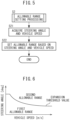
- FIG. 5 is a flow chart explaining content of allowable range setting processing.
- the control device 4 acquires the steering angle, which is one of the steering parameters in a correlative relationship with the steering operation of the steering wheel, and the vehicle speed.
- the steering parameter other than the steering angle for example, the angle (turning angle) of the left and right front wheels (turning wheels) of the vehicle may be mentioned. Note that regarding the vehicle speed as well, it may be replaced with another parameter in a correlative relationship with the vehicle speed.
- the control device 4 refers to the map of FIG. 6 set by experiments in advance etc. and sets the allowable range to the first allowable range or the second allowable range based on the steering angle and the vehicle speed.
- the first allowable range is made a range optimized by experiments in advance etc. as an allowable range when driving through a straight section.
- the second allowable range is made a range optimized by experiments in advance etc. as an allowable range when driving through a curved section, for example, is made an allowable range expanded by exactly a predetermined amount from the first allowable range to the side in the direction of the curve.
- the allowable range is set to the first allowable range if the steering angle is less than the expansion threshold value set corresponding to the vehicle speed and is set to the second allowable range if it is the greater than or equal to the expansion threshold value.
- the expansion threshold value basically is set to become smaller the higher the vehicle speed. This is because, as shown in FIG. 7 , a driver basically tends to look farther ahead the higher the vehicle speed.
- map of FIG. 6 is in the end just one example and can be suitably set in accordance with the steering characteristics of the vehicle model and the handle shape (circular shape, D-shape, U-shape, etc.) etc.
- step S3 the control device 4 judges whether it was possible to detect the facial orientation of the driver. If possible to detect the facial orientation of the driver, the control device 4 proceeds to the processing of step S4. On the other hand, if not possible to detect the facial orientation of the driver, the control device 4 proceeds to the processing of step S 15.
- step S4 the control device 4 judges if it was possible to detect the line-of-sight direction of the driver. If possible to detect the line-of-sight direction of the driver, the control device 4 proceeds to the processing of step S5. On the other hand, if not possible to detect the line-of-sight direction of the driver, the control device 4 proceeds to the processing of step S7.
- step S5 considering the fact that if the distance from the driver monitor camera 1 to the face of the driver becomes greater than or equal to a predetermined distance, the precision of detection of the line-of-sight direction of the driver tends to deteriorate, if the distance from the driver monitor camera 1 to the face of the driver is less than a predetermined distance, the control device 4 proceeds to the processing of step S6. On the other hand, if the distance from the driver monitor camera 1 to the face of the driver is greater than or equal to a predetermined distance, the control device 4 proceeds to the processing of step S7.
- the control device 4 sets the line-of-sight vector based on the line-of-sight direction of the driver.
- the control device 4 sets a vector extending from the position of the eyes of the driver (viewpoint position) toward the line-of-sight direction as the line-of-sight vector.
- the control device 4 sets the line-of-sight vector based on the facial orientation of the driver.
- the control device 4 sets a vector extending toward the direction of the facial orientation of the driver as the line-of-sight vector.
- step S8 the control device 4 judges whether the line-of-sight vector is passing through the allowable range set at step S2.
- the control device 4 judges that the driver is not driving distracted and proceeds to the processing of step S14 if the line-of-sight vector is passing through the allowable range.
- the control device 4 judges that the driver is driving distracted and proceeds to the processing of step S9 if the line-of-sight vector is not passing through the allowable range.
- the control device 4 judges whether a continued distracted driving flag F has been set to 1.
- the continued distracted driving flag F is a flag set to 1 when starting distracted driving.
- the initial value of the continued distracted driving flag F is set to 0. If the continued distracted driving flag F is set to 1 (that is, if the driver is continuing to drive distracted from the previous processing), the control device 4 proceeds to the processing of step S11. On the other hand, if the continued distracted driving flag F is set to 0 (that is, if the driver driving distracted is detected the first time by the current processing), the control device 4 proceeds to the processing of step S10.
- control device 4 sets the continued distracted driving flag F to 1.
- the control device 4 increases the continued distracted driving time period T by exactly a predetermined time period ⁇ T.
- the predetermined time period ⁇ T is a time period corresponding to one frame of the driver monitor camera 1.
- the control device 4 judges whether the continued distracted driving time period T has become greater than or equal to the distracted driving judgment time period Tthr.
- the distracted driving judgment time period Tthr can be made any value. At the present embodiment, it is made 2 seconds. If the continued distracted driving time period T is greater than or equal to the distracted driving judgment time period Tthr, the control device 4 proceeds to the processing of step S13. On the other hand, if the continued distracted driving time period T is less than the distracted driving judgment time period Tthr, the control device 4 ends the current processing.
- the control device 4 issues a distracted driving warning to the driver through the output device 2.
- the method and content of the distracted driving warning are not particularly limited.
- the warning may be issued by an audio announcement that the driver is driving distracted, the warning may be issued by issuing a warning sound, the warning may be issued by displaying image information or text information on a display, or the warning may be issued by combining the same.
- control device 4 sets the continued distracted driving flag F to 0.
- the control device 4 issues a warning through the output device 2 to the driver that his face cannot be recognized.
- the method and content of the distracted driving warning are also not particularly limited.
- the warning may be issued by a method similar to a distracted driving warning.
- the driver state detection device 100 is provided with the driver monitor camera 1 capturing the appearance of a driver of a vehicle to generate an image of the driver appearance and the control device 4.
- the control device 4 is configured so as to detect the facial orientation or the line-of-sight direction of the driver based on the image of the appearance, judge that the driver is driving distracted when the facial orientation or the line-of-sight direction of the driver is maintained for greater than or equal to a predetermined time period in a range at the outside from the allowable range allowed as the facial orientation or the line-of-sight direction of the driver, and set the allowable range based on the steering angle of the steering wheel of the vehicle (steering parameter in which is in a correlative relationship with steering operation of the steering wheel) and the speed of the vehicle.
- control device 4 is configured so as to set the allowable range to a first allowable range if the steering angle of the steering wheel is less than an expansion threshold value set in accordance with a speed of the vehicle, set the allowable range to a second allowable range broader than the first allowable range if the steering angle of the steering wheel is greater than or equal to the expansion threshold value, and make the expansion threshold value smaller when the speed of the vehicle is high compared to when it is low.
- a driver basically tends to look farther ahead the higher the vehicle speed. Therefore, the higher the vehicle speed, even if the curvature of the curve is small (that is, even if the steering angle is small), the more the line-of-sight vector tends to be directed to the side in the direction of the curve (that is, the side in direction of advance of the vehicle changed by the steering operation). Therefore, when the speed of the vehicle is high, compared to when it is low, it is possible to make the expansion threshold value smaller to thereby suitably expand the allowable range in accordance with the speed of the vehicle.
- control device 4 is configured so that, when setting the allowable range to the second allowable range, the range at the side in the direction of advance of the vehicle changed by the steering operation is expanded from the first allowable range by exactly a predetermined amount, so it is possible to suitably expand the allowable range.
- the driver state detection device 100 is further provided with an output device 2 for providing notifications to the driver.
- the control device 4 is configured so as to provide notification regarding distracted driving through the output device 2 to the driver when it is judged that the driver is driving distracted, so it is possible to make the driver not continue driving distracted.
- the computer program (distracted driving judgment processing) run at the control device 4 may be provided in a computer readable portable storage medium such as a magnetic recording medium or optical recording medium.
Landscapes
- Engineering & Computer Science (AREA)
- Automation & Control Theory (AREA)
- Mechanical Engineering (AREA)
- Transportation (AREA)
- Physics & Mathematics (AREA)
- Human Computer Interaction (AREA)
- General Physics & Mathematics (AREA)
- Multimedia (AREA)
- Theoretical Computer Science (AREA)
- Mathematical Physics (AREA)
- Health & Medical Sciences (AREA)
- General Health & Medical Sciences (AREA)
- Oral & Maxillofacial Surgery (AREA)
- Ophthalmology & Optometry (AREA)
- Chemical & Material Sciences (AREA)
- Combustion & Propulsion (AREA)
- Traffic Control Systems (AREA)
Abstract
Description
- The present invention relates to a driver state detection device.
- PTL 1 (
Japanese Unexamined Patent Publication No. 2019-87143 - PTL 2 (
Japanese Unexamined Patent Publication No. 2019-87029 - However, in the case of the conventional driver state detection device described in the above-mentioned
PTL 1, when information on the shape of the road ahead cannot be acquired, the left-right direction range allowed as the facial orientation or line of sight of the driver cannot be expanded, so when operating the steering wheel to change the direction of advance of the vehicle to the left or right, it is liable to end up being judged that the driver is driving distracted despite the driver viewing the direction of the curve. - Further, in the case of the conventional driver state detection device described in the above-mentioned
PTL 2, an operation such as operating a turn signal and sometimes not operating it triggers expansion of the left-right direction range allowed as the facial orientation or line of sight of the driver, so when the steering wheel is operated and the direction of advance of the vehicle is changed without such a triggering operation, it is liable to end up being judged that the driver is driving distracted despite the driver viewing the direction of advance (direction of adjoining lane at time of lane change). - The present invention was made focusing on such a problem and has as its object to keep from ending up judging that the driver is driving distracted regardless of not driving distracted.
- To solve the above problem, the driver state detection device according to one aspect of the present invention is provided with a driver monitor camera configured to capture an appearance of a driver of a vehicle to generate an image of the driver appearance and a control device. The control device is configured to detect the facial orientation or the line-of-sight direction of the driver based on the image of the appearance, judge that the driver is driving distracted when the facial orientation or the line-of-sight direction of the driver is maintained for greater than or equal to a predetermined time period in a range at the outside from the allowable range allowed as the facial orientation or the line-of-sight direction of the driver, and set the allowable range based on an operating parameter which is in a correlative relationship with a steering operation of the steering wheel of the vehicle and the speed of the vehicle.
- According to this aspect of the present invention, it is possible to expand the allowable range linked with a steering operation of the steering wheel - an essential operation performed when driving over a curved section. For this reason, it is possible to reliably expand the allowable range when driving through a curved section and keep from ending up judging that the driver is driving distracted despite not driving distracted.
-
-
FIG. 1 is a schematic view of the constitution of a driver state detection device according to an embodiment of the present invention. -
FIG. 2 is a flow chart explaining details of distracted driving judgment processing according to an embodiment of the present invention. -
FIG. 3A is a view explaining an allowable range. -
FIG. 3B is a view explaining an allowable range. -
FIG. 4A is a view explaining an allowable range. -
FIG. 4B is a view explaining an allowable range. -
FIG. 5 is a flow chart explaining content of allowable range setting processing according to an embodiment of the present invention. -
FIG. 6 is a view showing a map for setting an allowable range to a first allowable range or second allowable range based on a steering angle and vehicle speed. -
FIG. 7 is a view explaining there is a tendency for the driver to view farther ahead the higher the vehicle speed. - Below, referring to the drawings, an embodiment of the present invention will be explained in detail. Note that, in the following explanation, similar component elements are assigned the same reference notation.
-
FIG. 1 is a schematic view of the configuration of a driverstate detection device 100 according to one embodiment of the present invention. - The driver
state detection device 100 is a device mounted in a vehicle and detecting a state of a driver of the vehicle and is provided with adriver monitor camera 1, anoutput device 2,sensors 3, and acontrol device 4. - The
driver monitor camera 1 captures the driver appearance, including his face, by a predetermined frame rate (for example, 10 Hz to 40 Hz) and generates an image of the driver appearance in which the driver appearance is captured. Thedriver monitor camera 1 sends the generated image of the driver appearance to thecontrol device 4 each time generating the image of the driver appearance. Thedriver monitor camera 1 is, for example, attached to a steering column. - The
output device 2 is a device for providing notifications to the driver through physical senses of the driver (for example, vision, hearing, touch, etc.) In the present embodiment, as theoutput device 2, a display 21 (for example, meter display, center display, heads up display, etc.) arranged at a position which the driver can view and aspeaker 22 outputting audio to the inside of the vehicle are provided. Thedisplay 21 displays information corresponding to a display signal output from the control device 4 (for example, text information or image information). Thespeaker 22 outputs audio corresponding to a display signal output from thecontrol device 4. - The
sensors 3 acquire data required for setting an allowable range allowed as the later explained facial orientation or line-of-sight direction of the driver. In the present embodiment, thesensors 3 include asteering angle sensor 31 for detecting a rotational angle of the steering wheel (below, referred to as the "steering angle") and avehicle speed sensor 32 for detecting a vehicle speed. - The
control device 4 is an ECU (electronic control unit) provided with acommunication part 41,storage part 42, and processingpart 43. - The
communication part 41 is provided with an interface circuit for connecting thecontrol device 4 to aninternal vehicle network 5. Thecommunication part 41 supplies to theprocessing part 43 the data received from thedriver monitor camera 1 orsensors 3 through theinternal vehicle network 5. Further, thecommunication part 41 sends to theoutput device 2 through theinternal vehicle network 5 the display signal and audio signal output from theprocessing part 43. - The
storage part 42 has an HDD (hard disk drive) or SSD (solid state drive), semiconductor memory, or other storage medium and stores the various computer programs, data, etc. used for processing at theprocessing part 43. - The
processing part 43 has one or more CPUs (central processing unit) and their peripheral circuits and runs various types of computer programs stored in thestorage part 42 to comprehensively control the overall operation of the driverstate detection device 100, for example, is a processor. Giving one example of the processing which theprocessing part 43 performs, for example, theprocessing part 43 detects if the driver is driving distracted as the state of the driver and, when possible to judge that the driver is driving distracted, warns the driver through theoutput device 2. Below, the content of the distracted driving judgment processing which thisprocessing part 43 and in turn thecontrol device 4 perform will be explained with reference toFIG. 2 etc. -
FIG. 2 is a flow chart explaining details of distracted driving judgment processing according to the present embodiment. Thecontrol device 4 performs this routine for example every time receiving an image of the driver appearance from thedriver monitor camera 1. - At step S1, the
control device 4 detects the facial orientation of the driver, the line-of-sight direction of the driver, and the distance from thedriver monitor camera 1 to the face of the driver based on the image of the driver appearance received from thedriver monitor camera 1. - The methods of detection of these are not particularly limited, but the
control device 4 can, for example, analyze the image of the driver appearance to detect the portions of features of the face such as the eyes, nose, or mouth of the driver and compare the positions of these with 3D models of standard faces stored in thestorage part 42 so as to detect the facial orientation of the 3D model which the positions of the portions of the features of the face best match as the facial orientation of the driver. Further, thecontrol device 4 can, for example, analyze the image of the driver appearance to detect the position of the center of the pupil (that is, the position of point of view of the driver) serving as a moving point and the position of a purkinje image (corneal reflected image) serving as a reference point and detect the line-of-sight direction of the driver based on the positional relationship of the purkinje image and the center of the pupil (position of moving point with respect to reference point). Further, thecontrol device 4, for example, analyzes the image of the driver appearance to detect the size of the face of the driver and compares this with the sizes of standard faces stored in thestorage part 42 so as to detect the distance from thedriver monitor camera 1 to the face of the driver. The image of the driver appearance can be analyzed by, for example, being input to a convolutional neural network (CNN) having a plurality of convolution layers connected in series from the input side to the output side. - At step S2, the
control device 4 performs processing for setting the allowable range allowed as the facial orientation of the driver or the line-of-sight direction. Below, the allowable ranges will be explained referring toFIG. 3A, FIG. 3B ,FIG. 4A and FIG. 4B and details of the processing for setting the allowable ranges will be explained referring toFIG. 5 - The
control device 4 according to the present embodiment is configured, as shown inFIG. 3A , to judge that the driver is not driving distracted if a line-of-sight vector extending in the direction of the facial orientation of the driver or a line-of-sight vector extending from the position of the eyes of the driver (viewpoint position) toward the line-of-sight direction is passing an allowable range set at a predetermined position at the front in the direction of advance of the vehicle and having a predetermined height and width and, on the other hand, as shown inFIG. 3B , to judge that the driver is driving distracted if the line-of-sight vector is not passing the allowable range. - Here, as shown in
FIG. 4A , when driving through a curved section (including left and right turn sections), compared with when driving through a straight section, the line-of-sight direction of the driver tends to move toward the side in the direction of the curve. For this reason, if the allowable range ends up being made the same between when driving through a straight section and when driving through a curved section, when driving through a curved section, the line-of-sight vector will easily not pass through the allowable range but pass through a range outside of It, and despite the driver viewing a vehicle in the front (despite not driving distracted), it is liable to be judged that the driver is driving distracted. For this reason, when driving through a curved section, as shown inFIG. 4B , it is desirable to expand the allowable range to the side in the direction of the curve (inFIG. 4B , the right side). - Therefore, in the present embodiment, it is made possible to expand the allowable angle based on a steering parameter in a correlative relationship with a steering operation of a steering wheel - an essential operation performed along with characteristics of a curved section (for example curvature etc.)
-
FIG. 5 is a flow chart explaining content of allowable range setting processing. - At step S21, the
control device 4 acquires the steering angle, which is one of the steering parameters in a correlative relationship with the steering operation of the steering wheel, and the vehicle speed. As a steering parameter other than the steering angle, for example, the angle (turning angle) of the left and right front wheels (turning wheels) of the vehicle may be mentioned. Note that regarding the vehicle speed as well, it may be replaced with another parameter in a correlative relationship with the vehicle speed. - At step S22, the
control device 4 refers to the map ofFIG. 6 set by experiments in advance etc. and sets the allowable range to the first allowable range or the second allowable range based on the steering angle and the vehicle speed. The first allowable range is made a range optimized by experiments in advance etc. as an allowable range when driving through a straight section. The second allowable range is made a range optimized by experiments in advance etc. as an allowable range when driving through a curved section, for example, is made an allowable range expanded by exactly a predetermined amount from the first allowable range to the side in the direction of the curve. - Note that, as shown in the map of
FIG. 6 , the allowable range is set to the first allowable range if the steering angle is less than the expansion threshold value set corresponding to the vehicle speed and is set to the second allowable range if it is the greater than or equal to the expansion threshold value. The expansion threshold value basically is set to become smaller the higher the vehicle speed. This is because, as shown inFIG. 7 , a driver basically tends to look farther ahead the higher the vehicle speed. Therefore, the higher the vehicle speed, even if the curvature of the curve is small (that is, even if the steering angle is small), the easier it is for the line-of-sight vector to be directed to the side in the direction of the curve (that is, to the side in the direction of advance of the vehicle changed by a steering operation). - Note that, the map of
FIG. 6 is in the end just one example and can be suitably set in accordance with the steering characteristics of the vehicle model and the handle shape (circular shape, D-shape, U-shape, etc.) etc. - Returning to
FIG. 2 , at step S3, thecontrol device 4 judges whether it was possible to detect the facial orientation of the driver. If possible to detect the facial orientation of the driver, thecontrol device 4 proceeds to the processing of step S4. On the other hand, if not possible to detect the facial orientation of the driver, thecontrol device 4 proceeds to the processing ofstep S 15. - At step S4, the
control device 4 judges if it was possible to detect the line-of-sight direction of the driver. If possible to detect the line-of-sight direction of the driver, thecontrol device 4 proceeds to the processing of step S5. On the other hand, if not possible to detect the line-of-sight direction of the driver, thecontrol device 4 proceeds to the processing of step S7. - At step S5, considering the fact that if the distance from the
driver monitor camera 1 to the face of the driver becomes greater than or equal to a predetermined distance, the precision of detection of the line-of-sight direction of the driver tends to deteriorate, if the distance from thedriver monitor camera 1 to the face of the driver is less than a predetermined distance, thecontrol device 4 proceeds to the processing of step S6. On the other hand, if the distance from thedriver monitor camera 1 to the face of the driver is greater than or equal to a predetermined distance, thecontrol device 4 proceeds to the processing of step S7. - At step S6, the
control device 4 sets the line-of-sight vector based on the line-of-sight direction of the driver. In the present embodiment, thecontrol device 4 sets a vector extending from the position of the eyes of the driver (viewpoint position) toward the line-of-sight direction as the line-of-sight vector. - At step S7, the
control device 4 sets the line-of-sight vector based on the facial orientation of the driver. In the present embodiment, thecontrol device 4 sets a vector extending toward the direction of the facial orientation of the driver as the line-of-sight vector. - At step S8, the
control device 4 judges whether the line-of-sight vector is passing through the allowable range set at step S2. Thecontrol device 4 judges that the driver is not driving distracted and proceeds to the processing of step S14 if the line-of-sight vector is passing through the allowable range. On the other hand, thecontrol device 4 judges that the driver is driving distracted and proceeds to the processing of step S9 if the line-of-sight vector is not passing through the allowable range. - At step S9, the
control device 4 judges whether a continued distracted driving flag F has been set to 1. The continued distracted driving flag F is a flag set to 1 when starting distracted driving. The initial value of the continued distracted driving flag F is set to 0. If the continued distracted driving flag F is set to 1 (that is, if the driver is continuing to drive distracted from the previous processing), thecontrol device 4 proceeds to the processing of step S11. On the other hand, if the continued distracted driving flag F is set to 0 (that is, if the driver driving distracted is detected the first time by the current processing), thecontrol device 4 proceeds to the processing of step S10. - At step S10, the
control device 4 sets the continued distracted driving flag F to 1. - At step S11, the
control device 4 increases the continued distracted driving time period T by exactly a predetermined time period ΔT. In the present embodiment, the predetermined time period ΔT is a time period corresponding to one frame of thedriver monitor camera 1. - At step S12, the
control device 4 judges whether the continued distracted driving time period T has become greater than or equal to the distracted driving judgment time period Tthr. The distracted driving judgment time period Tthr can be made any value. At the present embodiment, it is made 2 seconds. If the continued distracted driving time period T is greater than or equal to the distracted driving judgment time period Tthr, thecontrol device 4 proceeds to the processing of step S13. On the other hand, if the continued distracted driving time period T is less than the distracted driving judgment time period Tthr, thecontrol device 4 ends the current processing. - At step S13, the
control device 4 issues a distracted driving warning to the driver through theoutput device 2. The method and content of the distracted driving warning are not particularly limited. For example, the warning may be issued by an audio announcement that the driver is driving distracted, the warning may be issued by issuing a warning sound, the warning may be issued by displaying image information or text information on a display, or the warning may be issued by combining the same. - At step S14, the
control device 4 sets the continued distracted driving flag F to 0. - At step S15, the
control device 4 issues a warning through theoutput device 2 to the driver that his face cannot be recognized. The method and content of the distracted driving warning are also not particularly limited. For example, the warning may be issued by a method similar to a distracted driving warning. - The driver
state detection device 100 according to the present embodiment explained above is provided with thedriver monitor camera 1 capturing the appearance of a driver of a vehicle to generate an image of the driver appearance and thecontrol device 4. Thecontrol device 4 is configured so as to detect the facial orientation or the line-of-sight direction of the driver based on the image of the appearance, judge that the driver is driving distracted when the facial orientation or the line-of-sight direction of the driver is maintained for greater than or equal to a predetermined time period in a range at the outside from the allowable range allowed as the facial orientation or the line-of-sight direction of the driver, and set the allowable range based on the steering angle of the steering wheel of the vehicle (steering parameter in which is in a correlative relationship with steering operation of the steering wheel) and the speed of the vehicle. - In this way, in the present embodiment, it is possible to expand the allowable range linked with a steering operation of the steering wheel - which is an essential operation performed in accordance with a characteristic of a curved section (for example, curvature etc.) when driving over a curved section. For this reason, it is possible to reliably expand the allowable range when driving through a curved section and keep from ending up judging that the driver is driving distracted despite not driving distracted.
- Further, in the present embodiment, the
control device 4 is configured so as to set the allowable range to a first allowable range if the steering angle of the steering wheel is less than an expansion threshold value set in accordance with a speed of the vehicle, set the allowable range to a second allowable range broader than the first allowable range if the steering angle of the steering wheel is greater than or equal to the expansion threshold value, and make the expansion threshold value smaller when the speed of the vehicle is high compared to when it is low. - As explained above, a driver basically tends to look farther ahead the higher the vehicle speed. Therefore, the higher the vehicle speed, even if the curvature of the curve is small (that is, even if the steering angle is small), the more the line-of-sight vector tends to be directed to the side in the direction of the curve (that is, the side in direction of advance of the vehicle changed by the steering operation). Therefore, when the speed of the vehicle is high, compared to when it is low, it is possible to make the expansion threshold value smaller to thereby suitably expand the allowable range in accordance with the speed of the vehicle.
- Further, in the present embodiment, the
control device 4 is configured so that, when setting the allowable range to the second allowable range, the range at the side in the direction of advance of the vehicle changed by the steering operation is expanded from the first allowable range by exactly a predetermined amount, so it is possible to suitably expand the allowable range. - Further, the driver
state detection device 100 according to the present embodiment is further provided with anoutput device 2 for providing notifications to the driver. Thecontrol device 4 is configured so as to provide notification regarding distracted driving through theoutput device 2 to the driver when it is judged that the driver is driving distracted, so it is possible to make the driver not continue driving distracted. - Above, an embodiment of the present invention was explained, but the above embodiment only shows part of the examples of application of the present invention and is not intended to limit the technical scope of the present invention to the specific constitution of the embodiment.
- For example, in the above embodiment, the computer program (distracted driving judgment processing) run at the
control device 4 may be provided in a computer readable portable storage medium such as a magnetic recording medium or optical recording medium.
Claims (5)
- A driver state detection device (100) comprising:a driver monitor camera (1) configured to capture the appearance of a driver of a vehicle to generate an image of the driver appearance; anda control device (4), whereinthe control device (4) is configured to:detect the facial orientation or the line-of-sight direction of the driver based on the image of the appearance;judge that the driver is driving distracted when the facial orientation or the line-of-sight direction of the driver is maintained for greater than or equal to a predetermined time period in a range at the outside from the allowable range allowed as the facial orientation or the line-of-sight direction of the driver; andset the allowable range based on an operating parameter which is in a correlative relationship with steering operation of the steering wheel of the vehicle and the speed of the vehicle.
- The driver state detection device (100) according to claim 1, wherein
the control device (4) is configured to:set the allowable range to a first allowable range if the steering parameter is less than an expansion threshold value set in accordance with a speed of the vehicle;set the allowable range to a second allowable range broader than the first allowable range if the steering parameter is greater than or equal to the expansion threshold value; andmake the expansion threshold value smaller when the speed of the vehicle is high compared to when it is low. - The driver state detection device (100) according to claim 2, wherein
the control device (4) is configured to make the range at the side in the direction of advance of the vehicle changed by the steering operation broader than the first allowable range by exactly a predetermined amount when setting the allowable range to the second allowable range. - The driver state detection device (100) according to any one of claim 1 to claim 3, whereinthe driver state detection device (100) further comprises an output device (2) configured to provide notifications to the driver, andthe control device (4) is configured to provide notifications relating to distracted driving to the driver through the output device when it is judged that the driver is driving distracted.
- The driver state detection device (100) according to any one of claim 1 to claim 3, wherein
the steering parameter is a steering angle of a steering wheel or a turning angle of turning wheels of the vehicle.
Applications Claiming Priority (1)
| Application Number | Priority Date | Filing Date | Title |
|---|---|---|---|
| JP2023007500A JP2024103261A (en) | 2023-01-20 | 2023-01-20 | Driver status detection device |
Publications (2)
| Publication Number | Publication Date |
|---|---|
| EP4403396A1 true EP4403396A1 (en) | 2024-07-24 |
| EP4403396B1 EP4403396B1 (en) | 2025-08-27 |
Family
ID=89121928
Family Applications (1)
| Application Number | Title | Priority Date | Filing Date |
|---|---|---|---|
| EP23214958.3A Active EP4403396B1 (en) | 2023-01-20 | 2023-12-07 | Driver state detection device |
Country Status (4)
| Country | Link |
|---|---|
| US (1) | US12497052B2 (en) |
| EP (1) | EP4403396B1 (en) |
| JP (1) | JP2024103261A (en) |
| CN (1) | CN118372836A (en) |
Citations (5)
| Publication number | Priority date | Publication date | Assignee | Title |
|---|---|---|---|---|
| US20120057749A1 (en) * | 2010-09-03 | 2012-03-08 | Honda Motor Co., Ltd. | Inattention determining device |
| US20180201276A1 (en) * | 2017-01-18 | 2018-07-19 | Toyota Jidosha Kabushiki Kaisha | Driver condition detection system |
| JP2019087143A (en) | 2017-11-09 | 2019-06-06 | トヨタ自動車株式会社 | Driver state detection apparatus |
| JP2019087029A (en) | 2017-11-07 | 2019-06-06 | トヨタ自動車株式会社 | Driver state detection apparatus |
| US20220324457A1 (en) * | 2021-04-09 | 2022-10-13 | Ford Global Technologies, Llc | Eyes-on-road detection |
Family Cites Families (6)
| Publication number | Priority date | Publication date | Assignee | Title |
|---|---|---|---|---|
| KR101736306B1 (en) * | 2013-02-27 | 2017-05-29 | 한국전자통신연구원 | Apparatus and method for copiloting between vehicle and driver |
| JP6265146B2 (en) * | 2014-05-27 | 2018-01-24 | 株式会社デンソー | Warning device |
| JP6930383B2 (en) * | 2017-11-07 | 2021-09-01 | トヨタ自動車株式会社 | Vehicle control device |
| JP6844568B2 (en) * | 2018-03-27 | 2021-03-17 | 日本電気株式会社 | Extra findings determination device, extra findings determination system, extra findings determination method, program |
| CN112997229A (en) * | 2018-11-13 | 2021-06-18 | 索尼公司 | Information processing apparatus, information processing method, and program |
| US11080568B2 (en) * | 2019-04-26 | 2021-08-03 | Samsara Inc. | Object-model based event detection system |
-
2023
- 2023-01-20 JP JP2023007500A patent/JP2024103261A/en active Pending
- 2023-12-07 EP EP23214958.3A patent/EP4403396B1/en active Active
-
2024
- 2024-01-11 CN CN202410041524.9A patent/CN118372836A/en active Pending
- 2024-01-18 US US18/415,649 patent/US12497052B2/en active Active
Patent Citations (5)
| Publication number | Priority date | Publication date | Assignee | Title |
|---|---|---|---|---|
| US20120057749A1 (en) * | 2010-09-03 | 2012-03-08 | Honda Motor Co., Ltd. | Inattention determining device |
| US20180201276A1 (en) * | 2017-01-18 | 2018-07-19 | Toyota Jidosha Kabushiki Kaisha | Driver condition detection system |
| JP2019087029A (en) | 2017-11-07 | 2019-06-06 | トヨタ自動車株式会社 | Driver state detection apparatus |
| JP2019087143A (en) | 2017-11-09 | 2019-06-06 | トヨタ自動車株式会社 | Driver state detection apparatus |
| US20220324457A1 (en) * | 2021-04-09 | 2022-10-13 | Ford Global Technologies, Llc | Eyes-on-road detection |
Also Published As
| Publication number | Publication date |
|---|---|
| JP2024103261A (en) | 2024-08-01 |
| US20240246542A1 (en) | 2024-07-25 |
| EP4403396B1 (en) | 2025-08-27 |
| CN118372836A (en) | 2024-07-23 |
| US12497052B2 (en) | 2025-12-16 |
Similar Documents
| Publication | Publication Date | Title |
|---|---|---|
| US12346498B2 (en) | Primary preview region and gaze based driver distraction detection | |
| US9694680B2 (en) | System and method for determining drowsy state of driver | |
| JP7058800B2 (en) | Display control device, display control method, and display control program | |
| JP4946682B2 (en) | Vehicle travel support device | |
| EP2960131A2 (en) | Warning device and travel control device | |
| JP6693427B2 (en) | Driver status detector | |
| JP2009040107A (en) | Image display control device and image display control system | |
| JP2016103249A (en) | Driving support device and driving support method | |
| CN112622774B (en) | Vehicle and method for providing information around vehicle | |
| JP7019394B2 (en) | Visual target detection device, visual target detection method, and program | |
| JP4936060B2 (en) | Vehicle travel support device | |
| JP5644414B2 (en) | Awakening level determination device, awakening level determination method, and program | |
| JP5030142B2 (en) | Concentration evaluation device and vehicle display device using the same | |
| EP4403396B1 (en) | Driver state detection device | |
| JP2017191367A (en) | Safe driving support device and safe driving support program | |
| KR102906380B1 (en) | Apparatus and method for recognizing storke symptoms of driver | |
| JP7275586B2 (en) | Video processing device and video processing method | |
| US12534088B2 (en) | Distraction judgment device, distraction judgment method, and nontransitory computer storage medium | |
| US12466316B2 (en) | Notification control device and notification control method | |
| US20240375641A1 (en) | Control device for vehicle, control method for vehicle, and nontransitory computer recording medium | |
| US20260109367A1 (en) | Driver assistance control device, driver assistance method, and nontransitory computer storage medium | |
| JP6992493B2 (en) | Operating condition determination device and operating condition determination method | |
| US20250282348A1 (en) | Control device for vehicle, control method for vehicle, and nontransitory computer storage medium | |
| JP2024146040A (en) | Vehicle control device, vehicle control method, and computer program | |
| JP2026042519A (en) | Gaze direction detection device |
Legal Events
| Date | Code | Title | Description |
|---|---|---|---|
| PUAI | Public reference made under article 153(3) epc to a published international application that has entered the european phase |
Free format text: ORIGINAL CODE: 0009012 |
|
| STAA | Information on the status of an ep patent application or granted ep patent |
Free format text: STATUS: REQUEST FOR EXAMINATION WAS MADE |
|
| 17P | Request for examination filed |
Effective date: 20231207 |
|
| AK | Designated contracting states |
Kind code of ref document: A1 Designated state(s): AL AT BE BG CH CY CZ DE DK EE ES FI FR GB GR HR HU IE IS IT LI LT LU LV MC ME MK MT NL NO PL PT RO RS SE SI SK SM TR |
|
| GRAP | Despatch of communication of intention to grant a patent |
Free format text: ORIGINAL CODE: EPIDOSNIGR1 |
|
| STAA | Information on the status of an ep patent application or granted ep patent |
Free format text: STATUS: GRANT OF PATENT IS INTENDED |
|
| INTG | Intention to grant announced |
Effective date: 20250326 |
|
| GRAS | Grant fee paid |
Free format text: ORIGINAL CODE: EPIDOSNIGR3 |
|
| GRAA | (expected) grant |
Free format text: ORIGINAL CODE: 0009210 |
|
| STAA | Information on the status of an ep patent application or granted ep patent |
Free format text: STATUS: THE PATENT HAS BEEN GRANTED |
|
| AK | Designated contracting states |
Kind code of ref document: B1 Designated state(s): AL AT BE BG CH CY CZ DE DK EE ES FI FR GB GR HR HU IE IS IT LI LT LU LV MC ME MK MT NL NO PL PT RO RS SE SI SK SM TR |
|
| REG | Reference to a national code |
Ref country code: CH Ref legal event code: EP |
|
| REG | Reference to a national code |
Ref country code: DE Ref legal event code: R096 Ref document number: 602023006120 Country of ref document: DE |
|
| REG | Reference to a national code |
Ref country code: IE Ref legal event code: FG4D |
|
| REG | Reference to a national code |
Ref country code: NL Ref legal event code: MP Effective date: 20250827 |
|
| PG25 | Lapsed in a contracting state [announced via postgrant information from national office to epo] |
Ref country code: IS Free format text: LAPSE BECAUSE OF FAILURE TO SUBMIT A TRANSLATION OF THE DESCRIPTION OR TO PAY THE FEE WITHIN THE PRESCRIBED TIME-LIMIT Effective date: 20251227 |
|
| PGFP | Annual fee paid to national office [announced via postgrant information from national office to epo] |
Ref country code: DE Payment date: 20251028 Year of fee payment: 3 |
|
| PG25 | Lapsed in a contracting state [announced via postgrant information from national office to epo] |
Ref country code: NO Free format text: LAPSE BECAUSE OF FAILURE TO SUBMIT A TRANSLATION OF THE DESCRIPTION OR TO PAY THE FEE WITHIN THE PRESCRIBED TIME-LIMIT Effective date: 20251127 |
|
| REG | Reference to a national code |
Ref country code: LT Ref legal event code: MG9D |
|
| PG25 | Lapsed in a contracting state [announced via postgrant information from national office to epo] |
Ref country code: PT Free format text: LAPSE BECAUSE OF FAILURE TO SUBMIT A TRANSLATION OF THE DESCRIPTION OR TO PAY THE FEE WITHIN THE PRESCRIBED TIME-LIMIT Effective date: 20251229 |
|
| PG25 | Lapsed in a contracting state [announced via postgrant information from national office to epo] |
Ref country code: FI Free format text: LAPSE BECAUSE OF FAILURE TO SUBMIT A TRANSLATION OF THE DESCRIPTION OR TO PAY THE FEE WITHIN THE PRESCRIBED TIME-LIMIT Effective date: 20250827 |
|
| PG25 | Lapsed in a contracting state [announced via postgrant information from national office to epo] |
Ref country code: HR Free format text: LAPSE BECAUSE OF FAILURE TO SUBMIT A TRANSLATION OF THE DESCRIPTION OR TO PAY THE FEE WITHIN THE PRESCRIBED TIME-LIMIT Effective date: 20250827 Ref country code: NL Free format text: LAPSE BECAUSE OF FAILURE TO SUBMIT A TRANSLATION OF THE DESCRIPTION OR TO PAY THE FEE WITHIN THE PRESCRIBED TIME-LIMIT Effective date: 20250827 |
|
| PGFP | Annual fee paid to national office [announced via postgrant information from national office to epo] |
Ref country code: FR Payment date: 20251117 Year of fee payment: 3 |
|
| PG25 | Lapsed in a contracting state [announced via postgrant information from national office to epo] |
Ref country code: GR Free format text: LAPSE BECAUSE OF FAILURE TO SUBMIT A TRANSLATION OF THE DESCRIPTION OR TO PAY THE FEE WITHIN THE PRESCRIBED TIME-LIMIT Effective date: 20251128 |
|
| PG25 | Lapsed in a contracting state [announced via postgrant information from national office to epo] |
Ref country code: SE Free format text: LAPSE BECAUSE OF FAILURE TO SUBMIT A TRANSLATION OF THE DESCRIPTION OR TO PAY THE FEE WITHIN THE PRESCRIBED TIME-LIMIT Effective date: 20250827 |
|
| PG25 | Lapsed in a contracting state [announced via postgrant information from national office to epo] |
Ref country code: LV Free format text: LAPSE BECAUSE OF FAILURE TO SUBMIT A TRANSLATION OF THE DESCRIPTION OR TO PAY THE FEE WITHIN THE PRESCRIBED TIME-LIMIT Effective date: 20250827 |
|
| PG25 | Lapsed in a contracting state [announced via postgrant information from national office to epo] |
Ref country code: PL Free format text: LAPSE BECAUSE OF FAILURE TO SUBMIT A TRANSLATION OF THE DESCRIPTION OR TO PAY THE FEE WITHIN THE PRESCRIBED TIME-LIMIT Effective date: 20250827 Ref country code: BG Free format text: LAPSE BECAUSE OF FAILURE TO SUBMIT A TRANSLATION OF THE DESCRIPTION OR TO PAY THE FEE WITHIN THE PRESCRIBED TIME-LIMIT Effective date: 20250827 |
|
| PG25 | Lapsed in a contracting state [announced via postgrant information from national office to epo] |
Ref country code: RS Free format text: LAPSE BECAUSE OF FAILURE TO SUBMIT A TRANSLATION OF THE DESCRIPTION OR TO PAY THE FEE WITHIN THE PRESCRIBED TIME-LIMIT Effective date: 20251127 |
|
| PG25 | Lapsed in a contracting state [announced via postgrant information from national office to epo] |
Ref country code: ES Free format text: LAPSE BECAUSE OF FAILURE TO SUBMIT A TRANSLATION OF THE DESCRIPTION OR TO PAY THE FEE WITHIN THE PRESCRIBED TIME-LIMIT Effective date: 20250827 |
|
| REG | Reference to a national code |
Ref country code: AT Ref legal event code: MK05 Ref document number: 1829634 Country of ref document: AT Kind code of ref document: T Effective date: 20250827 |
|
| PG25 | Lapsed in a contracting state [announced via postgrant information from national office to epo] |
Ref country code: RO Free format text: LAPSE BECAUSE OF FAILURE TO SUBMIT A TRANSLATION OF THE DESCRIPTION OR TO PAY THE FEE WITHIN THE PRESCRIBED TIME-LIMIT Effective date: 20250827 |
|
| PG25 | Lapsed in a contracting state [announced via postgrant information from national office to epo] |
Ref country code: SM Free format text: LAPSE BECAUSE OF FAILURE TO SUBMIT A TRANSLATION OF THE DESCRIPTION OR TO PAY THE FEE WITHIN THE PRESCRIBED TIME-LIMIT Effective date: 20250827 |
|
| PG25 | Lapsed in a contracting state [announced via postgrant information from national office to epo] |
Ref country code: DK Free format text: LAPSE BECAUSE OF FAILURE TO SUBMIT A TRANSLATION OF THE DESCRIPTION OR TO PAY THE FEE WITHIN THE PRESCRIBED TIME-LIMIT Effective date: 20250827 |
|
| PG25 | Lapsed in a contracting state [announced via postgrant information from national office to epo] |
Ref country code: AT Free format text: LAPSE BECAUSE OF FAILURE TO SUBMIT A TRANSLATION OF THE DESCRIPTION OR TO PAY THE FEE WITHIN THE PRESCRIBED TIME-LIMIT Effective date: 20250827 |
|
| PG25 | Lapsed in a contracting state [announced via postgrant information from national office to epo] |
Ref country code: IT Free format text: LAPSE BECAUSE OF FAILURE TO SUBMIT A TRANSLATION OF THE DESCRIPTION OR TO PAY THE FEE WITHIN THE PRESCRIBED TIME-LIMIT Effective date: 20250827 |
|
| PG25 | Lapsed in a contracting state [announced via postgrant information from national office to epo] |
Ref country code: CZ Free format text: LAPSE BECAUSE OF FAILURE TO SUBMIT A TRANSLATION OF THE DESCRIPTION OR TO PAY THE FEE WITHIN THE PRESCRIBED TIME-LIMIT Effective date: 20250827 |
|
| PG25 | Lapsed in a contracting state [announced via postgrant information from national office to epo] |
Ref country code: SK Free format text: LAPSE BECAUSE OF FAILURE TO SUBMIT A TRANSLATION OF THE DESCRIPTION OR TO PAY THE FEE WITHIN THE PRESCRIBED TIME-LIMIT Effective date: 20250827 Ref country code: EE Free format text: LAPSE BECAUSE OF FAILURE TO SUBMIT A TRANSLATION OF THE DESCRIPTION OR TO PAY THE FEE WITHIN THE PRESCRIBED TIME-LIMIT Effective date: 20250827 |