EP4403337A1 - Sealing device for pouch-type secondary battery - Google Patents
Sealing device for pouch-type secondary battery Download PDFInfo
- Publication number
- EP4403337A1 EP4403337A1 EP23857587.2A EP23857587A EP4403337A1 EP 4403337 A1 EP4403337 A1 EP 4403337A1 EP 23857587 A EP23857587 A EP 23857587A EP 4403337 A1 EP4403337 A1 EP 4403337A1
- Authority
- EP
- European Patent Office
- Prior art keywords
- sealing
- pouch
- light
- transmitting material
- light transmitting
- Prior art date
- Legal status (The legal status is an assumption and is not a legal conclusion. Google has not performed a legal analysis and makes no representation as to the accuracy of the status listed.)
- Granted
Links
Images


Classifications
-
- H—ELECTRICITY
- H01—ELECTRIC ELEMENTS
- H01M—PROCESSES OR MEANS, e.g. BATTERIES, FOR THE DIRECT CONVERSION OF CHEMICAL ENERGY INTO ELECTRICAL ENERGY
- H01M10/00—Secondary cells; Manufacture thereof
- H01M10/04—Construction or manufacture in general
- H01M10/0404—Machines for assembling batteries
-
- B—PERFORMING OPERATIONS; TRANSPORTING
- B23—MACHINE TOOLS; METAL-WORKING NOT OTHERWISE PROVIDED FOR
- B23K—SOLDERING OR UNSOLDERING; WELDING; CLADDING OR PLATING BY SOLDERING OR WELDING; CUTTING BY APPLYING HEAT LOCALLY, e.g. FLAME CUTTING; WORKING BY LASER BEAM
- B23K26/00—Working by laser beam, e.g. welding, cutting or boring
- B23K26/009—Working by laser beam, e.g. welding, cutting or boring using a non-absorbing, e.g. transparent, reflective or refractive, layer on the workpiece
-
- B—PERFORMING OPERATIONS; TRANSPORTING
- B23—MACHINE TOOLS; METAL-WORKING NOT OTHERWISE PROVIDED FOR
- B23K—SOLDERING OR UNSOLDERING; WELDING; CLADDING OR PLATING BY SOLDERING OR WELDING; CUTTING BY APPLYING HEAT LOCALLY, e.g. FLAME CUTTING; WORKING BY LASER BEAM
- B23K26/00—Working by laser beam, e.g. welding, cutting or boring
- B23K26/02—Positioning or observing the workpiece, e.g. with respect to the point of impact; Aligning, aiming or focusing the laser beam
- B23K26/06—Shaping the laser beam, e.g. by masks or multi-focusing
- B23K26/064—Shaping the laser beam, e.g. by masks or multi-focusing by means of optical elements, e.g. lenses, mirrors or prisms
- B23K26/0648—Shaping the laser beam, e.g. by masks or multi-focusing by means of optical elements, e.g. lenses, mirrors or prisms comprising lenses
-
- B—PERFORMING OPERATIONS; TRANSPORTING
- B29—WORKING OF PLASTICS; WORKING OF SUBSTANCES IN A PLASTIC STATE IN GENERAL
- B29C—SHAPING OR JOINING OF PLASTICS; SHAPING OF MATERIAL IN A PLASTIC STATE, NOT OTHERWISE PROVIDED FOR; AFTER-TREATMENT OF THE SHAPED PRODUCTS, e.g. REPAIRING
- B29C65/00—Joining or sealing of preformed parts, e.g. welding of plastics materials; Apparatus therefor
- B29C65/02—Joining or sealing of preformed parts, e.g. welding of plastics materials; Apparatus therefor by heating, with or without pressure
- B29C65/14—Joining or sealing of preformed parts, e.g. welding of plastics materials; Apparatus therefor by heating, with or without pressure using wave energy, i.e. electromagnetic radiation, or particle radiation
- B29C65/1403—Joining or sealing of preformed parts, e.g. welding of plastics materials; Apparatus therefor by heating, with or without pressure using wave energy, i.e. electromagnetic radiation, or particle radiation characterised by the type of electromagnetic or particle radiation
- B29C65/1409—Visible light radiation
-
- B—PERFORMING OPERATIONS; TRANSPORTING
- B29—WORKING OF PLASTICS; WORKING OF SUBSTANCES IN A PLASTIC STATE IN GENERAL
- B29C—SHAPING OR JOINING OF PLASTICS; SHAPING OF MATERIAL IN A PLASTIC STATE, NOT OTHERWISE PROVIDED FOR; AFTER-TREATMENT OF THE SHAPED PRODUCTS, e.g. REPAIRING
- B29C65/00—Joining or sealing of preformed parts, e.g. welding of plastics materials; Apparatus therefor
- B29C65/02—Joining or sealing of preformed parts, e.g. welding of plastics materials; Apparatus therefor by heating, with or without pressure
- B29C65/14—Joining or sealing of preformed parts, e.g. welding of plastics materials; Apparatus therefor by heating, with or without pressure using wave energy, i.e. electromagnetic radiation, or particle radiation
- B29C65/1403—Joining or sealing of preformed parts, e.g. welding of plastics materials; Apparatus therefor by heating, with or without pressure using wave energy, i.e. electromagnetic radiation, or particle radiation characterised by the type of electromagnetic or particle radiation
- B29C65/1412—Infrared [IR] radiation
- B29C65/1416—Near-infrared radiation [NIR]
-
- B—PERFORMING OPERATIONS; TRANSPORTING
- B29—WORKING OF PLASTICS; WORKING OF SUBSTANCES IN A PLASTIC STATE IN GENERAL
- B29C—SHAPING OR JOINING OF PLASTICS; SHAPING OF MATERIAL IN A PLASTIC STATE, NOT OTHERWISE PROVIDED FOR; AFTER-TREATMENT OF THE SHAPED PRODUCTS, e.g. REPAIRING
- B29C65/00—Joining or sealing of preformed parts, e.g. welding of plastics materials; Apparatus therefor
- B29C65/02—Joining or sealing of preformed parts, e.g. welding of plastics materials; Apparatus therefor by heating, with or without pressure
- B29C65/14—Joining or sealing of preformed parts, e.g. welding of plastics materials; Apparatus therefor by heating, with or without pressure using wave energy, i.e. electromagnetic radiation, or particle radiation
- B29C65/1429—Joining or sealing of preformed parts, e.g. welding of plastics materials; Apparatus therefor by heating, with or without pressure using wave energy, i.e. electromagnetic radiation, or particle radiation characterised by the way of heating the interface
- B29C65/1445—Joining or sealing of preformed parts, e.g. welding of plastics materials; Apparatus therefor by heating, with or without pressure using wave energy, i.e. electromagnetic radiation, or particle radiation characterised by the way of heating the interface heating both sides of the joint
-
- B—PERFORMING OPERATIONS; TRANSPORTING
- B29—WORKING OF PLASTICS; WORKING OF SUBSTANCES IN A PLASTIC STATE IN GENERAL
- B29C—SHAPING OR JOINING OF PLASTICS; SHAPING OF MATERIAL IN A PLASTIC STATE, NOT OTHERWISE PROVIDED FOR; AFTER-TREATMENT OF THE SHAPED PRODUCTS, e.g. REPAIRING
- B29C65/00—Joining or sealing of preformed parts, e.g. welding of plastics materials; Apparatus therefor
- B29C65/02—Joining or sealing of preformed parts, e.g. welding of plastics materials; Apparatus therefor by heating, with or without pressure
- B29C65/18—Joining or sealing of preformed parts, e.g. welding of plastics materials; Apparatus therefor by heating, with or without pressure using heated tools
-
- B—PERFORMING OPERATIONS; TRANSPORTING
- B29—WORKING OF PLASTICS; WORKING OF SUBSTANCES IN A PLASTIC STATE IN GENERAL
- B29C—SHAPING OR JOINING OF PLASTICS; SHAPING OF MATERIAL IN A PLASTIC STATE, NOT OTHERWISE PROVIDED FOR; AFTER-TREATMENT OF THE SHAPED PRODUCTS, e.g. REPAIRING
- B29C65/00—Joining or sealing of preformed parts, e.g. welding of plastics materials; Apparatus therefor
- B29C65/02—Joining or sealing of preformed parts, e.g. welding of plastics materials; Apparatus therefor by heating, with or without pressure
- B29C65/18—Joining or sealing of preformed parts, e.g. welding of plastics materials; Apparatus therefor by heating, with or without pressure using heated tools
- B29C65/24—Joining or sealing of preformed parts, e.g. welding of plastics materials; Apparatus therefor by heating, with or without pressure using heated tools characterised by the means for heating the tool
- B29C65/245—Joining or sealing of preformed parts, e.g. welding of plastics materials; Apparatus therefor by heating, with or without pressure using heated tools characterised by the means for heating the tool the heat transfer being achieved contactless, e.g. by radiation
-
- B—PERFORMING OPERATIONS; TRANSPORTING
- B29—WORKING OF PLASTICS; WORKING OF SUBSTANCES IN A PLASTIC STATE IN GENERAL
- B29C—SHAPING OR JOINING OF PLASTICS; SHAPING OF MATERIAL IN A PLASTIC STATE, NOT OTHERWISE PROVIDED FOR; AFTER-TREATMENT OF THE SHAPED PRODUCTS, e.g. REPAIRING
- B29C66/00—General aspects of processes or apparatus for joining preformed parts
- B29C66/01—General aspects dealing with the joint area or with the area to be joined
- B29C66/05—Particular design of joint configurations
- B29C66/10—Particular design of joint configurations particular design of the joint cross-sections
- B29C66/11—Joint cross-sections comprising a single joint-segment, i.e. one of the parts to be joined comprising a single joint-segment in the joint cross-section
- B29C66/112—Single lapped joints
- B29C66/1122—Single lap to lap joints, i.e. overlap joints
-
- B—PERFORMING OPERATIONS; TRANSPORTING
- B29—WORKING OF PLASTICS; WORKING OF SUBSTANCES IN A PLASTIC STATE IN GENERAL
- B29C—SHAPING OR JOINING OF PLASTICS; SHAPING OF MATERIAL IN A PLASTIC STATE, NOT OTHERWISE PROVIDED FOR; AFTER-TREATMENT OF THE SHAPED PRODUCTS, e.g. REPAIRING
- B29C66/00—General aspects of processes or apparatus for joining preformed parts
- B29C66/01—General aspects dealing with the joint area or with the area to be joined
- B29C66/05—Particular design of joint configurations
- B29C66/10—Particular design of joint configurations particular design of the joint cross-sections
- B29C66/13—Single flanged joints; Fin-type joints; Single hem joints; Edge joints; Interpenetrating fingered joints; Other specific particular designs of joint cross-sections not provided for in groups B29C66/11 - B29C66/12
- B29C66/133—Fin-type joints, the parts to be joined being flexible
-
- B—PERFORMING OPERATIONS; TRANSPORTING
- B29—WORKING OF PLASTICS; WORKING OF SUBSTANCES IN A PLASTIC STATE IN GENERAL
- B29C—SHAPING OR JOINING OF PLASTICS; SHAPING OF MATERIAL IN A PLASTIC STATE, NOT OTHERWISE PROVIDED FOR; AFTER-TREATMENT OF THE SHAPED PRODUCTS, e.g. REPAIRING
- B29C66/00—General aspects of processes or apparatus for joining preformed parts
- B29C66/40—General aspects of joining substantially flat articles, e.g. plates, sheets or web-like materials; Making flat seams in tubular or hollow articles; Joining single elements to substantially flat surfaces
- B29C66/41—Joining substantially flat articles ; Making flat seams in tubular or hollow articles
- B29C66/43—Joining a relatively small portion of the surface of said articles
- B29C66/431—Joining the articles to themselves
- B29C66/4312—Joining the articles to themselves for making flat seams in tubular or hollow articles, e.g. transversal seams
- B29C66/43121—Closing the ends of tubular or hollow single articles, e.g. closing the ends of bags
-
- B—PERFORMING OPERATIONS; TRANSPORTING
- B29—WORKING OF PLASTICS; WORKING OF SUBSTANCES IN A PLASTIC STATE IN GENERAL
- B29C—SHAPING OR JOINING OF PLASTICS; SHAPING OF MATERIAL IN A PLASTIC STATE, NOT OTHERWISE PROVIDED FOR; AFTER-TREATMENT OF THE SHAPED PRODUCTS, e.g. REPAIRING
- B29C66/00—General aspects of processes or apparatus for joining preformed parts
- B29C66/40—General aspects of joining substantially flat articles, e.g. plates, sheets or web-like materials; Making flat seams in tubular or hollow articles; Joining single elements to substantially flat surfaces
- B29C66/41—Joining substantially flat articles ; Making flat seams in tubular or hollow articles
- B29C66/43—Joining a relatively small portion of the surface of said articles
- B29C66/433—Casing-in, i.e. enclosing an element between two sheets by an outlined seam
-
- B—PERFORMING OPERATIONS; TRANSPORTING
- B29—WORKING OF PLASTICS; WORKING OF SUBSTANCES IN A PLASTIC STATE IN GENERAL
- B29C—SHAPING OR JOINING OF PLASTICS; SHAPING OF MATERIAL IN A PLASTIC STATE, NOT OTHERWISE PROVIDED FOR; AFTER-TREATMENT OF THE SHAPED PRODUCTS, e.g. REPAIRING
- B29C66/00—General aspects of processes or apparatus for joining preformed parts
- B29C66/70—General aspects of processes or apparatus for joining preformed parts characterised by the composition, physical properties or the structure of the material of the parts to be joined; Joining with non-plastics material
- B29C66/71—General aspects of processes or apparatus for joining preformed parts characterised by the composition, physical properties or the structure of the material of the parts to be joined; Joining with non-plastics material characterised by the composition of the plastics material of the parts to be joined
-
- B—PERFORMING OPERATIONS; TRANSPORTING
- B29—WORKING OF PLASTICS; WORKING OF SUBSTANCES IN A PLASTIC STATE IN GENERAL
- B29C—SHAPING OR JOINING OF PLASTICS; SHAPING OF MATERIAL IN A PLASTIC STATE, NOT OTHERWISE PROVIDED FOR; AFTER-TREATMENT OF THE SHAPED PRODUCTS, e.g. REPAIRING
- B29C66/00—General aspects of processes or apparatus for joining preformed parts
- B29C66/70—General aspects of processes or apparatus for joining preformed parts characterised by the composition, physical properties or the structure of the material of the parts to be joined; Joining with non-plastics material
- B29C66/72—General aspects of processes or apparatus for joining preformed parts characterised by the composition, physical properties or the structure of the material of the parts to be joined; Joining with non-plastics material characterised by the structure of the material of the parts to be joined
- B29C66/723—General aspects of processes or apparatus for joining preformed parts characterised by the composition, physical properties or the structure of the material of the parts to be joined; Joining with non-plastics material characterised by the structure of the material of the parts to be joined being multi-layered
- B29C66/7232—General aspects of processes or apparatus for joining preformed parts characterised by the composition, physical properties or the structure of the material of the parts to be joined; Joining with non-plastics material characterised by the structure of the material of the parts to be joined being multi-layered comprising a non-plastics layer
- B29C66/72321—General aspects of processes or apparatus for joining preformed parts characterised by the composition, physical properties or the structure of the material of the parts to be joined; Joining with non-plastics material characterised by the structure of the material of the parts to be joined being multi-layered comprising a non-plastics layer consisting of metals or their alloys
-
- B—PERFORMING OPERATIONS; TRANSPORTING
- B29—WORKING OF PLASTICS; WORKING OF SUBSTANCES IN A PLASTIC STATE IN GENERAL
- B29C—SHAPING OR JOINING OF PLASTICS; SHAPING OF MATERIAL IN A PLASTIC STATE, NOT OTHERWISE PROVIDED FOR; AFTER-TREATMENT OF THE SHAPED PRODUCTS, e.g. REPAIRING
- B29C66/00—General aspects of processes or apparatus for joining preformed parts
- B29C66/70—General aspects of processes or apparatus for joining preformed parts characterised by the composition, physical properties or the structure of the material of the parts to be joined; Joining with non-plastics material
- B29C66/73—General aspects of processes or apparatus for joining preformed parts characterised by the composition, physical properties or the structure of the material of the parts to be joined; Joining with non-plastics material characterised by the intensive physical properties of the material of the parts to be joined, by the optical properties of the material of the parts to be joined, by the extensive physical properties of the parts to be joined, by the state of the material of the parts to be joined or by the material of the parts to be joined being a thermoplastic or a thermoset
- B29C66/739—General aspects of processes or apparatus for joining preformed parts characterised by the composition, physical properties or the structure of the material of the parts to be joined; Joining with non-plastics material characterised by the intensive physical properties of the material of the parts to be joined, by the optical properties of the material of the parts to be joined, by the extensive physical properties of the parts to be joined, by the state of the material of the parts to be joined or by the material of the parts to be joined being a thermoplastic or a thermoset characterised by the material of the parts to be joined being a thermoplastic or a thermoset
- B29C66/7392—General aspects of processes or apparatus for joining preformed parts characterised by the composition, physical properties or the structure of the material of the parts to be joined; Joining with non-plastics material characterised by the intensive physical properties of the material of the parts to be joined, by the optical properties of the material of the parts to be joined, by the extensive physical properties of the parts to be joined, by the state of the material of the parts to be joined or by the material of the parts to be joined being a thermoplastic or a thermoset characterised by the material of the parts to be joined being a thermoplastic or a thermoset characterised by the material of at least one of the parts being a thermoplastic
- B29C66/73921—General aspects of processes or apparatus for joining preformed parts characterised by the composition, physical properties or the structure of the material of the parts to be joined; Joining with non-plastics material characterised by the intensive physical properties of the material of the parts to be joined, by the optical properties of the material of the parts to be joined, by the extensive physical properties of the parts to be joined, by the state of the material of the parts to be joined or by the material of the parts to be joined being a thermoplastic or a thermoset characterised by the material of the parts to be joined being a thermoplastic or a thermoset characterised by the material of at least one of the parts being a thermoplastic characterised by the materials of both parts being thermoplastics
-
- B—PERFORMING OPERATIONS; TRANSPORTING
- B29—WORKING OF PLASTICS; WORKING OF SUBSTANCES IN A PLASTIC STATE IN GENERAL
- B29C—SHAPING OR JOINING OF PLASTICS; SHAPING OF MATERIAL IN A PLASTIC STATE, NOT OTHERWISE PROVIDED FOR; AFTER-TREATMENT OF THE SHAPED PRODUCTS, e.g. REPAIRING
- B29C66/00—General aspects of processes or apparatus for joining preformed parts
- B29C66/80—General aspects of machine operations or constructions and parts thereof
- B29C66/81—General aspects of the pressing elements, i.e. the elements applying pressure on the parts to be joined in the area to be joined, e.g. the welding jaws or clamps
- B29C66/812—General aspects of the pressing elements, i.e. the elements applying pressure on the parts to be joined in the area to be joined, e.g. the welding jaws or clamps characterised by the composition, by the structure, by the intensive physical properties or by the optical properties of the material constituting the pressing elements, e.g. constituting the welding jaws or clamps
- B29C66/8126—General aspects of the pressing elements, i.e. the elements applying pressure on the parts to be joined in the area to be joined, e.g. the welding jaws or clamps characterised by the composition, by the structure, by the intensive physical properties or by the optical properties of the material constituting the pressing elements, e.g. constituting the welding jaws or clamps characterised by the intensive physical properties or by the optical properties of the material constituting the pressing elements, e.g. constituting the welding jaws or clamps
- B29C66/81266—Optical properties, e.g. transparency, reflectivity
- B29C66/81267—Transparent to electromagnetic radiation, e.g. to visible light
-
- B—PERFORMING OPERATIONS; TRANSPORTING
- B29—WORKING OF PLASTICS; WORKING OF SUBSTANCES IN A PLASTIC STATE IN GENERAL
- B29C—SHAPING OR JOINING OF PLASTICS; SHAPING OF MATERIAL IN A PLASTIC STATE, NOT OTHERWISE PROVIDED FOR; AFTER-TREATMENT OF THE SHAPED PRODUCTS, e.g. REPAIRING
- B29C66/00—General aspects of processes or apparatus for joining preformed parts
- B29C66/80—General aspects of machine operations or constructions and parts thereof
- B29C66/81—General aspects of the pressing elements, i.e. the elements applying pressure on the parts to be joined in the area to be joined, e.g. the welding jaws or clamps
- B29C66/814—General aspects of the pressing elements, i.e. the elements applying pressure on the parts to be joined in the area to be joined, e.g. the welding jaws or clamps characterised by the design of the pressing elements, e.g. of the welding jaws or clamps
- B29C66/8141—General aspects of the pressing elements, i.e. the elements applying pressure on the parts to be joined in the area to be joined, e.g. the welding jaws or clamps characterised by the design of the pressing elements, e.g. of the welding jaws or clamps characterised by the surface geometry of the part of the pressing elements, e.g. welding jaws or clamps, coming into contact with the parts to be joined
- B29C66/81427—General aspects of the pressing elements, i.e. the elements applying pressure on the parts to be joined in the area to be joined, e.g. the welding jaws or clamps characterised by the design of the pressing elements, e.g. of the welding jaws or clamps characterised by the surface geometry of the part of the pressing elements, e.g. welding jaws or clamps, coming into contact with the parts to be joined comprising a single ridge, e.g. for making a weakening line; comprising a single tooth
-
- B—PERFORMING OPERATIONS; TRANSPORTING
- B29—WORKING OF PLASTICS; WORKING OF SUBSTANCES IN A PLASTIC STATE IN GENERAL
- B29C—SHAPING OR JOINING OF PLASTICS; SHAPING OF MATERIAL IN A PLASTIC STATE, NOT OTHERWISE PROVIDED FOR; AFTER-TREATMENT OF THE SHAPED PRODUCTS, e.g. REPAIRING
- B29C66/00—General aspects of processes or apparatus for joining preformed parts
- B29C66/80—General aspects of machine operations or constructions and parts thereof
- B29C66/83—General aspects of machine operations or constructions and parts thereof characterised by the movement of the joining or pressing tools
- B29C66/832—Reciprocating joining or pressing tools
- B29C66/8322—Joining or pressing tools reciprocating along one axis
- B29C66/83221—Joining or pressing tools reciprocating along one axis cooperating reciprocating tools, each tool reciprocating along one axis
-
- H—ELECTRICITY
- H01—ELECTRIC ELEMENTS
- H01M—PROCESSES OR MEANS, e.g. BATTERIES, FOR THE DIRECT CONVERSION OF CHEMICAL ENERGY INTO ELECTRICAL ENERGY
- H01M10/00—Secondary cells; Manufacture thereof
- H01M10/04—Construction or manufacture in general
- H01M10/0481—Compression means other than compression means for stacks of electrodes and separators
-
- H—ELECTRICITY
- H01—ELECTRIC ELEMENTS
- H01M—PROCESSES OR MEANS, e.g. BATTERIES, FOR THE DIRECT CONVERSION OF CHEMICAL ENERGY INTO ELECTRICAL ENERGY
- H01M10/00—Secondary cells; Manufacture thereof
- H01M10/04—Construction or manufacture in general
- H01M10/049—Processes for forming or storing electrodes in the battery container
-
- H—ELECTRICITY
- H01—ELECTRIC ELEMENTS
- H01M—PROCESSES OR MEANS, e.g. BATTERIES, FOR THE DIRECT CONVERSION OF CHEMICAL ENERGY INTO ELECTRICAL ENERGY
- H01M50/00—Constructional details or processes of manufacture of the non-active parts of electrochemical cells other than fuel cells, e.g. hybrid cells
- H01M50/10—Primary casings; Jackets or wrappings
- H01M50/147—Lids or covers
- H01M50/166—Lids or covers characterised by the methods of assembling casings with lids
- H01M50/169—Lids or covers characterised by the methods of assembling casings with lids by welding, brazing or soldering
-
- H—ELECTRICITY
- H01—ELECTRIC ELEMENTS
- H01M—PROCESSES OR MEANS, e.g. BATTERIES, FOR THE DIRECT CONVERSION OF CHEMICAL ENERGY INTO ELECTRICAL ENERGY
- H01M50/00—Constructional details or processes of manufacture of the non-active parts of electrochemical cells other than fuel cells, e.g. hybrid cells
- H01M50/10—Primary casings; Jackets or wrappings
- H01M50/183—Sealing members
-
- H—ELECTRICITY
- H05—ELECTRIC TECHNIQUES NOT OTHERWISE PROVIDED FOR
- H05B—ELECTRIC HEATING; ELECTRIC LIGHT SOURCES NOT OTHERWISE PROVIDED FOR; CIRCUIT ARRANGEMENTS FOR ELECTRIC LIGHT SOURCES, IN GENERAL
- H05B3/00—Ohmic-resistance heating
- H05B3/0033—Heating devices using lamps
-
- H—ELECTRICITY
- H05—ELECTRIC TECHNIQUES NOT OTHERWISE PROVIDED FOR
- H05B—ELECTRIC HEATING; ELECTRIC LIGHT SOURCES NOT OTHERWISE PROVIDED FOR; CIRCUIT ARRANGEMENTS FOR ELECTRIC LIGHT SOURCES, IN GENERAL
- H05B3/00—Ohmic-resistance heating
- H05B3/0033—Heating devices using lamps
- H05B3/0038—Heating devices using lamps for industrial applications
-
- B—PERFORMING OPERATIONS; TRANSPORTING
- B23—MACHINE TOOLS; METAL-WORKING NOT OTHERWISE PROVIDED FOR
- B23K—SOLDERING OR UNSOLDERING; WELDING; CLADDING OR PLATING BY SOLDERING OR WELDING; CUTTING BY APPLYING HEAT LOCALLY, e.g. FLAME CUTTING; WORKING BY LASER BEAM
- B23K2101/00—Articles made by soldering, welding or cutting
- B23K2101/36—Electric or electronic devices
- B23K2101/38—Conductors
-
- B—PERFORMING OPERATIONS; TRANSPORTING
- B29—WORKING OF PLASTICS; WORKING OF SUBSTANCES IN A PLASTIC STATE IN GENERAL
- B29L—INDEXING SCHEME ASSOCIATED WITH SUBCLASS B29C, RELATING TO PARTICULAR ARTICLES
- B29L2031/00—Other particular articles
- B29L2031/34—Electrical apparatus, e.g. sparking plugs or parts thereof
- B29L2031/3468—Batteries, accumulators or fuel cells
-
- B—PERFORMING OPERATIONS; TRANSPORTING
- B29—WORKING OF PLASTICS; WORKING OF SUBSTANCES IN A PLASTIC STATE IN GENERAL
- B29L—INDEXING SCHEME ASSOCIATED WITH SUBCLASS B29C, RELATING TO PARTICULAR ARTICLES
- B29L2031/00—Other particular articles
- B29L2031/712—Containers; Packaging elements or accessories, Packages
- B29L2031/7146—Battery-cases
-
- H—ELECTRICITY
- H01—ELECTRIC ELEMENTS
- H01M—PROCESSES OR MEANS, e.g. BATTERIES, FOR THE DIRECT CONVERSION OF CHEMICAL ENERGY INTO ELECTRICAL ENERGY
- H01M50/00—Constructional details or processes of manufacture of the non-active parts of electrochemical cells other than fuel cells, e.g. hybrid cells
- H01M50/10—Primary casings; Jackets or wrappings
- H01M50/102—Primary casings; Jackets or wrappings characterised by their shape or physical structure
- H01M50/105—Pouches or flexible bags
-
- H—ELECTRICITY
- H01—ELECTRIC ELEMENTS
- H01M—PROCESSES OR MEANS, e.g. BATTERIES, FOR THE DIRECT CONVERSION OF CHEMICAL ENERGY INTO ELECTRICAL ENERGY
- H01M50/00—Constructional details or processes of manufacture of the non-active parts of electrochemical cells other than fuel cells, e.g. hybrid cells
- H01M50/10—Primary casings; Jackets or wrappings
- H01M50/116—Primary casings; Jackets or wrappings characterised by the material
- H01M50/124—Primary casings; Jackets or wrappings characterised by the material having a layered structure
-
- Y—GENERAL TAGGING OF NEW TECHNOLOGICAL DEVELOPMENTS; GENERAL TAGGING OF CROSS-SECTIONAL TECHNOLOGIES SPANNING OVER SEVERAL SECTIONS OF THE IPC; TECHNICAL SUBJECTS COVERED BY FORMER USPC CROSS-REFERENCE ART COLLECTIONS [XRACs] AND DIGESTS
- Y02—TECHNOLOGIES OR APPLICATIONS FOR MITIGATION OR ADAPTATION AGAINST CLIMATE CHANGE
- Y02E—REDUCTION OF GREENHOUSE GAS [GHG] EMISSIONS, RELATED TO ENERGY GENERATION, TRANSMISSION OR DISTRIBUTION
- Y02E60/00—Enabling technologies; Technologies with a potential or indirect contribution to GHG emissions mitigation
- Y02E60/10—Energy storage using batteries
-
- Y—GENERAL TAGGING OF NEW TECHNOLOGICAL DEVELOPMENTS; GENERAL TAGGING OF CROSS-SECTIONAL TECHNOLOGIES SPANNING OVER SEVERAL SECTIONS OF THE IPC; TECHNICAL SUBJECTS COVERED BY FORMER USPC CROSS-REFERENCE ART COLLECTIONS [XRACs] AND DIGESTS
- Y02—TECHNOLOGIES OR APPLICATIONS FOR MITIGATION OR ADAPTATION AGAINST CLIMATE CHANGE
- Y02P—CLIMATE CHANGE MITIGATION TECHNOLOGIES IN THE PRODUCTION OR PROCESSING OF GOODS
- Y02P70/00—Climate change mitigation technologies in the production process for final industrial or consumer products
- Y02P70/50—Manufacturing or production processes characterised by the final manufactured product
Definitions
- the present invention relates to a sealing device used during case sealing in the manufacture of a pouch-type secondary battery.
- This application claims the benefit of priority to Korean Patent Applications No. 10-2022-0106088, filed on August 24, 2022 , the disclosure of which is incorporated herein by reference in its entirety.
- lithium secondary batteries with high energy density and discharge voltage have been commercialized and used in various forms.
- Lithium secondary batteries are classified into cylindrical secondary batteries, prismatic secondary batteries, and pouch-type secondary batteries according to their shape.
- pouch-type secondary batteries are being researched in various fields because they can be made into high-capacity, high-density secondary batteries by adjusting the thickness of the aluminum laminate sheet and can have various shapes.
- an aluminum laminated sheet is typically molded to form a storing part, an electrode assembly is stored in the storing part, and the periphery of the storing part is sealed.
- a conventional sealing device for a pouch-type secondary battery performs pressurization and heating with a single member.
- a sealing part of a pouch-type secondary battery case including a laminated sheet made of an outer resin layer, a metal layer, and an inner sealant layer is arranged with the inner sealant layer facing each other, and is sealed by placing it between pressurizing parts that can simultaneously heat and pressurize.
- the sealing device has the problem that it takes a lot of time for heat to be transferred from the outer resin layer to the inner sealant layer and causes damage to the outer resin layer.
- the sealing device for a pouch-type secondary battery like the sealing device for a pouch-type secondary battery according to the prior art, arranges a sealing part of a pouch-type case including an outer resin layer, a metal layer, and an inner sealant layer with the inner sealant layer facing each other, and places it between the pressurizing parts.
- the pressurizing part is characterized in that it is made of an infrared transmitting material and has an infrared irradiation part in the upper part.
- the infrared irradiation part rapidly heats only the metal layer of the sealing part of the pouch-type case and melts the inner sealant layer by the heated metal layer, thereby improving the sealing force while reducing the damage to the outer resin layer caused by conventional heat.
- the sealing device for a pouch-type secondary battery has a limitation that the power of the laser must be high to heat the metal layer disposed between the outer resin layer and the inner sealant layer.
- uneven heating of the pressurizing part may result in uneven sealing or quality imbalances such as wrinkles in the laminated sheet comprising the pouch-type case. If the laser power is increased to solve this problem, the low compressive strength of the pressurizing part may cause the pressurizing part to break when pressurized in a heated state.
- the present invention provides a sealing device for a pouch-type secondary battery including:
- the first light transmitting material may have a refractive index of 1.45 to 1.9 for a light having a wavelength of 980 nm, and may have a Mohs hardness of 8.0 or greater.
- the pressurizing part may include a sealing unit that heats and pressurizes the sealing part of the pouch-type case by contacting the sealing part of the pouch-type case; and a lens unit positioned between the light source part and the sealing unit to concentrate light irradiated from the light source part into the sealing unit, wherein the sealing unit may include a first light transmitting material.
- the lens unit may include one or more among a first light transmitting material and a second light transmitting material, and the second light transmitting material may satisfy Formula 2: 0.5 ⁇ TC 2 nd /RI 2 nd ⁇ 2 in Formula 2,
- the lens unit may be a cylinder lens.
- the lens unit may include a first light transmitting material and a second light transmitting material, and the first light transmitting material and the second light transmitting material may have a structure that is symmetrical with respect to a center line including a cross-sectional center of the lens unit.
- the light source part may irradiate light having a wavelength of 750 nm to 1,000 nm.
- the present invention provides a manufacturing method of a pouch-type secondary battery including:
- a sealing device for a pouch-type secondary battery includes a light source part for irradiating light and a pressurizing part for heating and pressurizing a sealing part of a pouch-type case using light irradiated by the light source part, but has a configuration in which a first light transmitting material having a high thermal conductivity and a high light refractive index is applied to a sealing unit of the pressurizing part that contacts the sealing part of the pouch-type case.
- the sealing device is capable of uniformly heating and sealing the sealing part of the pouch-type case, and it is possible to prevent damage of the sealing unit heated to a high temperature during sealing, so that the quality of the secondary battery can be improved, and at the same time, it has the advantage of improving processability and economy.
- the present invention provides a sealing device for a pouch-type secondary battery including:
- a sealing device for a pouch-type secondary battery includes a light source part for irradiating light and a pressurizing part for heating and pressurizing a sealing part of a pouch-type case using light irradiated by the light source part, and is characterized in that a first light transmitting material having a high thermal conductivity and a high light refractive index is applied to a sealing unit of the pressurizing part that contacts the sealing part of the pouch-type case. Accordingly, the sealing device can not only heat and seal the sealing part of the pouch-type case uniformly, but also prevent damage of the sealing unit heated to a high temperature during sealing, so that the quality of the secondary battery can be improved, and at the same time has the advantage of improving processability and economy.
- FIG. 1 is a perspective view schematically illustrating the main configuration of a sealing device according to the present invention. The following will be described in more detail with reference to FIG. 1 .
- the sealing device 100 for the pouch-type secondary battery includes a pressurizing part 120 located on the sealing part 11a of the pouch-type case 11 to heat and pressurize the sealing part 11a, and a light source part 110 to irradiate light to heat the pressurizing part 120.
- the light source part 110 plays a role in heating the pressurizing part 120.
- the light source part 110 may irradiate the pressurizing part 120 with light, and the irradiated light may be a laser in the form of a beam.
- the light may be light formed by a laser diode, and the emitted light may be an infrared laser, specifically an infrared laser with a wavelength of 750 nm to 1,000 nm; or an infrared laser with a wavelength of 800 nm to 980 nm.
- the infrared laser emitted from the light source part 110 may be irradiated at any one point among either the upper part and lower part of the sealing part 11a to be sealed, or may be irradiated at both the upper part and lower part of the sealing part 11a.
- the former case has the advantage of lower equipment costs compared to the latter case, and of avoiding possible damage to the laser diodes on opposite sides.
- the latter case has the advantage of using two light source parts 110 on both sides centered on the sealing part 11a, so that the melting of the sealant layer can be effectively achieved with less time required.
- the light source part 110 may be provided in plurality on the other side of the side where the pressurizing part 120 pressurizes the sealing part 11a of the pouch-type case, and the pressurizing part 120 and the light source part 110 may be disposed on the same line on the sealing part 11a of the pouch-type case. In this case, even if the light source part 110 and the pressurizing part 120 are spaced apart from each other, the loss of the infrared laser emitted by the pressurizing part 120 can be minimized.
- the light emitted from the light source part 110 is transmitted to the pressurizing part 120, and the light transmitted to the pressurizing part 120 can be concentrated to heat the sealing part 11a of the pouch-type case.
- the pressurizing part 120 may operate by pressurizing the sealing part 11a of the pouch-type case to maintain the sealant layers on the inside of the pouch-type case in a state of increased mutual adhesion, and in this state, the light source part 110 may heat the pressurizing part 120 by emitting an infrared laser.
- the sealant layer on the inside of the pouch-type case can be irradiated with high precision to effectively form the sealing part 11a, and the coupling force of the sealing part 11a can be further increased.
- the pressurizing part 120 may include a sealing unit 121 for heat compressing in contact with the sealing part 11a of the pouch-type case; and a lens unit 122 positioned between the light source part 110 and the sealing unit 121 to concentrate light irradiated from the light source part 110 into the sealing unit 121.
- the sealing unit 121 performs the function of pressurizing the sealing part 11a of the pouch-type case while transferring heat caused by the infrared laser concentrated through the lens unit 122 to the sealing part 11a for heating.
- the sealing unit 121 may have a flat plate shape arranged along the sealing part 11a of the pouch-type case, but it may also have a structure capable of preventing dispersion of the light source part inside the sealing unit 121 to prevent energy loss due to dispersion of the infrared laser, etc.
- the lens unit 122 may be mounted on one side of the sealing unit 121 to expand the irradiation range of the infrared laser irradiated by the light source part 110, and may serve to concentrate the incident light on the sealing unit 121.
- the lens unit 122 may be integrally formed with the sealing unit 121 but positioned between the light source part 110 and the sealing unit 121 along the path of the infrared laser.
- the lens unit 122 may refract and/or reflect the infrared laser emitted from the light source part 110 and guide it to the sealing unit 121.
- the lens unit 122 may have a convex shape on the side facing the sealing unit 121, and may preferably include a cylindrical lens with a side attached along the sealing unit 121.
- the pressurizing part 120 may include a first light transmitting material satisfying Formula 1 in order to concentrate the incident light from the light source part 110 onto the sealing part 11a of the pouch-type case, but to concentrate it uniformly on the front of the sealing part 11a while minimizing the energy loss thereof: 15 ⁇ TC 1 st / RI 1 st ⁇ 35 in Formula 1,
- Formula 1 shows the ratio of the thermal conductivity of the first light transmitting material to its refractive index for light having a wavelength of 980 nm.
- the infrared laser concentrated in the pressurizing part 120 is transmitted to the sealing part 11a of the pouch-type case in the form of thermal energy, and the energy conservation of the first light transmitting material can be inferred by reflecting the refractive index of light rather than the light transmissivity to the infrared laser.
- Formula 1 can indirectly indicate the energy conservation of the first light transmitting material to the infrared laser.
- the pressurizing part according to the present invention may include a first light transmitting material satisfying Formula 1 as 15 to 35 (i.e., 15 ⁇ TC 1st /RI 1st ⁇ 35), more specifically, Formula 1 as 15 to 35 (i.e., 15 ⁇ TC 1st /RI 1st ⁇ 35); 15 to 30 (i.e., 15 ⁇ TC 1st /RI 1st ⁇ 30); 20 to 35 (i.e., 20 ⁇ TC 1st /RI 1st ⁇ 35); 20 to 30 (i.e., 20 ⁇ TC 1st /RI 1st ⁇ 30); or 20 to 25 (i.e., 20 ⁇ TC 1st /RI 1st ⁇ 5).
- Formula 1 as 15 to 35 i.e., 15 ⁇ TC 1st /RI 1st ⁇ 35
- 15 to 30 i.e., 15 ⁇ TC 1st /RI 1st ⁇ 30
- 20 to 35 i.e.,
- the first light transmitting material may have a refractive index of 1.45 to 1.9 for light having a wavelength of 980 nm, more specifically, a refractive index of 1.45 to 1.85; 1.55 to 1.85; 1.65 to 1.85; or 1.75 to 1.85 for light having a wavelength of 980 nm.
- the first light transmitting material can minimize the energy loss of the infrared laser incident from the light source part 110, and can apply heat uniformly to the sealing part 11a of the pouch-type case. Furthermore, the residual heat in the sealing portion can be quickly dissipated, and thus the sealing thickness of the sealing part 11a can be uniformly formed.
- the first light transmitting material may exhibit a Mohs hardness in a particular range.
- the first light transmitting material may have a Mohs hardness of 8.0 or more, more specifically, 8.5 or more; or 9.0 or more.
- the first light transmitting material according to the present invention can prevent breakage under heating and pressurization conditions, thereby preventing damage to the sealing part 11a due to breakage of the pressurizing part 120 when sealing the sealing part 11a of the pouch-type case.
- the pressurizing part 120 may include a first light transmitting material, and in some cases, the first light transmitting material is included in a sealing unit 121 of the pressurizing part 120 that requires high thermal energy transfer efficiency and hardness, and the lens unit 122 attached to the sealing unit 121 may include one or more of the first light transmitting material and the second light transmitting material.
- the lens unit 122 may be made of a first light transmitting material, and in some cases may be made of a second light-transmitting material alone or in combination, as a relatively low thermal conductivity is required compared to the sealing unit 121.
- the lens unit 122 may include a second light transmitting material having a relatively low thermal conductivity and light refractive index compared to the first light transmitting material, and the second light transmitting material may satisfy Formula 2 below: 0.5 ⁇ TC 2 nd /RI 2 nd ⁇ 2 in Formula 2,
- Formula 2 shows the ratio of the thermal conductivity of the second light transmitting material to its refractive index for light having a wavelength of 980 nm.
- the infrared laser concentrated by the pressurizing part 120 is transmitted to the sealing part 11a of the pouch-type case in the form of heat energy, and the energy conservation of the second light transmitting material can be inferred by reflecting the refractive index of light rather than the light transmissivity to the infrared laser.
- Formula 2 can indirectly represent the energy conservation of the second light transmitting material for the infrared laser.
- the pressurizing part according to the invention may include a second light transmitting material satisfying Formula 2 as 0.5 to 2 (i.e., 0.5 ⁇ TC 2nd /RI 2nd ⁇ 2), and more specifically, a second light transmitting material satisfying Formula 2 as 0.5 to 1.9 (i.e., 0.5 ⁇ TC 2nd /RI 2nd ⁇ 1.9); 0.5 to 1.75 (i.e., 0.5 ⁇ TC 2nd /RI 2nd ⁇ 1.75); 0.5 to 1.5 (i.e., 0.5 ⁇ TC 2nd /RI 2nd ⁇ 1.5); or 0.5 to 1.35 (i.e., 0.5 ⁇ TC 2nd /RI 2nd ⁇ 1.35).
- the second light transmitting material may have a refractive index of 1.40 to 1.60 for light having a wavelength of 980 nm, and more specifically, may have a refractive index of 1.45 to 1.60; 1.45 to 1.55; or 1.50 to 1.55 for light having a wavelength of 980 nm.
- the second light transmitting material can concentrate the infrared laser incident from the light source part 110 to the sealing unit 121 with minimal energy loss.
- the lens unit 122 when the lens unit 122 includes a first light transmitting material and a second light transmitting material, it may include them to have a constant cross-sectional structure.
- the lens unit 122 may include a first light transmitting material 1st and a second light transmitting material 2nd so as to be symmetrical with respect to a center line C including a cross-sectional center.
- the center line C is parallel to the pressurization direction of the sealing unit 121 and may include a center of the sealing unit 121.
- the lens unit 122 may include only the second light transmitting material 2nd, as shown in FIG. 2(a) , and the first light transmitting material 1st and the second light transmitting material 2nd may be arranged so as to be symmetrical with respect to the center line C, as shown in Fig. 2(b) to 2(d) .
- the present invention can maximize the thermal energy of the infrared laser focused on the sealing unit 121, and can further increase the processability and economy of the lens unit 122 compared to a case in which the lens unit 122 is constituted by the first light-transmitting material 1st having a high hardness alone.
- the amount of energy concentrated on the sealing unit 121 can be adjusted, which has the advantage of being selectively applied depending on the type or size of the pouch-type case used in manufacturing the secondary battery.
- the first light transmitting material 1st and the second light transmitting material 2nd can be applied without being particularly limited if they satisfy the conditions of Formula 1 and Formula 2, respectively, described above.
- the first light transmitting material 1st and the second light transmitting material 2nd can be germanium, silicon, zinc sulfide, magnesium fluoride, sapphire, glass, quartz, and the like.
- the first light transmitting material can include sapphire (TC/RI: 22.2 ⁇ 25.7, refractive index: 1.75-1.8, Mohs hardness: 9), and the second light transmitting material can include quartz (TC/RI: 0.65-1.33, refractive index: 1.5-1.55, Mohs hardness: 6).
- the sealing device for a pouch-type secondary battery according to the present invention can not only heat and seal the sealing part of the pouch-type case uniformly, but also prevent the breakage of the sealing unit heated to a high temperature during sealing, so that the quality of the secondary battery can be improved, and at the same time have the advantage of improving processability and economy.
- the present invention provides a method for manufacturing a secondary battery using the above-described sealing device for a pouch-type secondary battery.
- the manufacturing method of the secondary battery according to the present invention has the advantage of improving the quality of the manufactured secondary battery by utilizing the sealing device of the present invention described above for sealing, so that a uniform and solid sealing of the sealing part is possible.
- the method includes storing an electrode assembly and electrolyte in a pouch-type case comprising a laminated sheet including a metal layer and an inner sealant layer, and including a storing part for storing the electrode assembly and a sealing part surrounding the storing part; disposing the above-described sealing device of the present invention at at least one point among an upper part and a lower part of the sealing part of the pouch-type case; and sealing the sealing part of the pouch-type case by pressurizing it while irradiating light from the light source part of the sealing device to a pressurizing part.
- storing the electrode assembly and the electrolyte in the pouch-type case may be performed in a manner conventional in the art as the step of storing the electrode assembly and the electrolyte, respectively, in the pouch-type case.
- the electrode assembly may be one among: a jelly roll type electrode assembly, wherein the electrode assembly is wound by stacking one or more negative electrodes, separators, and positive electrodes one after the other; a stack & folding type electrode assembly, wherein the unit cells with the negative electrodes, separators, and positive electrodes stacked one after the other are placed on a long film-like separator and then wound in a single direction; and a stack & folding electrode assembly wherein the unit cells with the negative electrodes, separators, and positive electrodes stacked one after the other are arranged in a long film-like separator and then wound in a zigzag direction.
- the pouch-type case may be made of a metal layer including an aluminum layer, and a laminated sheet including an inner sealant layer.
- the metal layer serves to prevent air, moisture, and the like from entering the interior of the battery.
- the material used for the metal layer is not particularly limited as long as it is a material with good formability and ductility and can be heated by infrared radiation.
- it can be made of an aluminum or an aluminum alloy material.
- the inner sealant layer serves to provide sealing by being thermally fused to each other by applied heat and pressure with the electrode assembly embedded therein, and is mainly composed of casting polypropylene (CPP) film.
- An adhesive layer may be added between the outer resin layer and the metal layer and/or between the metal layer and the inner sealant layer, which serves to compensate for the low adhesion between the layers on both sides of the adhesive layer.
- disposing the sealing device of the invention on the sealing part of the pouch-type case is performed by disposing the sealing device of the present invention on the upper part and/or lower part of the sealing part of the pouch-type case after the electrode assembly and electrolyte are stored in the pouch-type case.
- the above step may be performed by disposing a sealing device on an upper part and lower part of the sealing part of the pouch-type case, respectively.
- sealing the sealing part of the pouch-type case by pressurizing the sealing part is a step of sealing the sealing part, wherein light irradiation from a light source part of the sealing device disposed on the sealing part to the pressurizing part and pressurization of the sealing part of the pouch-type case may be performed simultaneously, and in some cases, light irradiation to the pressurizing part may be performed after pressurization of the sealing part of the pouch-type case.
- the light source part may emit an infrared laser to the pressurizing part, and the infrared laser may have a wavelength of 750 nm to 1,000 nm, or may have a wavelength of 800 nm to 980 nm. If the wavelength of the infrared laser is too long, it may not be sufficient to induce heating of the barrier metal layer or melting of the sealant layer, or it may take a long time, and conversely, if the wavelength is too short, it is undesirable because high energy may cause rupture of the battery case or fire, etc.
- the temperature at which the sealant layer is melted by the infrared laser irradiation may be from 180 to 300°C.
- a temperature outside the above temperature range is undesirable because it may not facilitate the formation of a substantially uniform sealing part due to insufficient melting or excessive melting.
- the pressure at which the pressurizing part of the sealing device pressurizes the sealing part of the pouch-type case is preferably in the range of 0.1 to 5 MPa.
- the pressure applied to the sealing part of the pouch-type case may be adjusted by a pressure gauge (not shown) provided on the sealing device to apply a constant pressure to the front of the sealing part.
- An electrode assembly and electrolyte were inserted into the pouch-type case, and the unsealed pouch cell with the electrode assembly and electrolyte inserted was fixed to the sealing device.
- a sealing device having a structure as shown in FIG. 1 was used.
- an infrared laser with a wavelength of 980 nm was irradiated to the lens unit of the pressurizing part (power: 80 to 85 W/cm 2 ) using the infrared diode of the light source part, and the sealing unit of the pressurizing part was used to pressurize the sealing part of the pouch-type case at 2 MPa and to seal the sealing part.
- the sealing unit of the pressurizing part is composed of a first light transmitting material
- the lens unit of the pressurizing part is composed of at least one of the first light transmitting material and the second light transmitting material.
- the respective properties of the first light transmitting material and the second light transmitting material and the cross-sectional structure of the lens unit are adjusted as shown in Table 1 below.
- the sealing quality of the sealing part was evaluated on pouch-type secondary batteries sealed in the Examples and Comparative Examples.
- the sealing device for a pouch-type secondary battery according to the present invention is capable of uniformly and securely sealing the sealing part of the pouch-type case.
- the secondary battery of the example using the sealing unit of the pressurizing part with a light transmitting material satisfying the conditions of Formula 1 was confirmed to have a maximum error rate of less than 5% based on the average thickness of the sealing part due to uniform sealing of the sealing part.
- the secondary battery of the comparative example using a sealing device with a light transmitting material applied that does not satisfy Formula 1 was found to have a maximum error rate of more than 10% based on the average thickness of the sealing part due to uneven sealing of the sealing part.
- the sealing device according to the present invention and the manufacturing method of a secondary battery using it can not only seal the sealing part of the pouch-type case uniformly, but also prevent the breakage of the sealing unit heated to a high temperature during sealing, so that the quality of the secondary battery can be improved, and at the same time, the processability and economy can be improved.
Landscapes
- Engineering & Computer Science (AREA)
- Mechanical Engineering (AREA)
- Physics & Mathematics (AREA)
- Chemical & Material Sciences (AREA)
- Chemical Kinetics & Catalysis (AREA)
- Electrochemistry (AREA)
- General Chemical & Material Sciences (AREA)
- Electromagnetism (AREA)
- Optics & Photonics (AREA)
- Manufacturing & Machinery (AREA)
- Health & Medical Sciences (AREA)
- Toxicology (AREA)
- Plasma & Fusion (AREA)
- Thermal Sciences (AREA)
- Sealing Battery Cases Or Jackets (AREA)
- Secondary Cells (AREA)
Abstract
Description
- The present invention relates to a sealing device used during case sealing in the manufacture of a pouch-type secondary battery. This application claims the benefit of priority to
Korean Patent Applications No. 10-2022-0106088, filed on August 24, 2022 - The demand for high-capacity and high-density batteries is increasing as devices that use batteries has become diversified. Among them, lithium secondary batteries with high energy density and discharge voltage have been commercialized and used in various forms.
- Lithium secondary batteries are classified into cylindrical secondary batteries, prismatic secondary batteries, and pouch-type secondary batteries according to their shape. Among them, pouch-type secondary batteries are being researched in various fields because they can be made into high-capacity, high-density secondary batteries by adjusting the thickness of the aluminum laminate sheet and can have various shapes.
- Regarding the pouch-type secondary batteries, an aluminum laminated sheet is typically molded to form a storing part, an electrode assembly is stored in the storing part, and the periphery of the storing part is sealed. In order to seal the periphery of the storing part to form a sealing part, a conventional sealing device for a pouch-type secondary battery performs pressurization and heating with a single member.
- In a conventional sealing device for a pouch-type secondary battery, a sealing part of a pouch-type secondary battery case including a laminated sheet made of an outer resin layer, a metal layer, and an inner sealant layer is arranged with the inner sealant layer facing each other, and is sealed by placing it between pressurizing parts that can simultaneously heat and pressurize. However, the sealing device has the problem that it takes a lot of time for heat to be transferred from the outer resin layer to the inner sealant layer and causes damage to the outer resin layer.
- To solve these problems, a method for sealing a pouch-type secondary battery using a laser has been developed. The sealing device for a pouch-type secondary battery, like the sealing device for a pouch-type secondary battery according to the prior art, arranges a sealing part of a pouch-type case including an outer resin layer, a metal layer, and an inner sealant layer with the inner sealant layer facing each other, and places it between the pressurizing parts.
- Here, the pressurizing part is characterized in that it is made of an infrared transmitting material and has an infrared irradiation part in the upper part. In addition, the infrared irradiation part rapidly heats only the metal layer of the sealing part of the pouch-type case and melts the inner sealant layer by the heated metal layer, thereby improving the sealing force while reducing the damage to the outer resin layer caused by conventional heat.
- However, the sealing device for a pouch-type secondary battery has a limitation that the power of the laser must be high to heat the metal layer disposed between the outer resin layer and the inner sealant layer. In addition, uneven heating of the pressurizing part may result in uneven sealing or quality imbalances such as wrinkles in the laminated sheet comprising the pouch-type case. If the laser power is increased to solve this problem, the low compressive strength of the pressurizing part may cause the pressurizing part to break when pressurized in a heated state.
- Therefore, there is a need to develop a sealing device for a pouch-type secondary battery and a method for manufacturing pouch-type secondary battery using the sealing device that can uniformly and safely seal the sealing part of a pouch-type secondary battery case.
-
Korean Patent Publication No. 10-2021-0156516 - Accordingly, it is an object of the present invention to provide a sealing device for a pouch-type secondary battery capable of uniformly and safely sealing a sealing part of a pouch-type secondary battery case, and a method for manufacturing a secondary battery using the sealing device.
- To address the problems described above, in an exemplary embodiment, the present invention provides a sealing device for a pouch-type secondary battery including:
- a pressurizing part configured to contact at least an upper surface or a lower surface of a sealing part of a pouch-type case; and
- a light source part for irradiating light to the pressurizing part,
- wherein the pressurizing part is made of a material through which light irradiated from the light source part is transmissible and includes a first light transmitting material satisfying Formula 1 below:
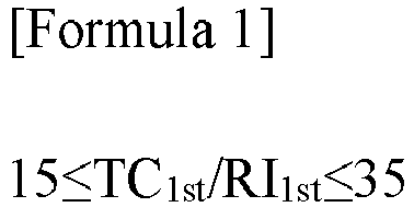
- TC1st represents a thermal conductivity (unit: W/m·K) of the first light transmitting material,
- RI1st represents a refractive index of a light of the first light transmitting material with a wavelength of 980 nm.
- Here, the first light transmitting material may have a refractive index of 1.45 to 1.9 for a light having a wavelength of 980 nm, and may have a Mohs hardness of 8.0 or greater.
- In addition, the pressurizing part may include a sealing unit that heats and pressurizes the sealing part of the pouch-type case by contacting the sealing part of the pouch-type case; and a lens unit positioned between the light source part and the sealing unit to concentrate light irradiated from the light source part into the sealing unit, wherein the sealing unit may include a first light transmitting material.
- Moreover, the lens unit may include one or more among a first light transmitting material and a second light transmitting material, and the second light transmitting material may satisfy Formula 2:

- TC2nd represents a thermal conductivity (unit: W/m K) of the second light transmitting material,
- RI2nd represents a refractive index of a light of the second light transmitting material with a wavelength of 980 nm.
- Here, the second light transmitting material has a refractive index of 1.40 to 1.60 for light having a wavelength of 980 nm.
- In addition, the lens unit may be a cylinder lens.
- In this case, the lens unit may include a first light transmitting material and a second light transmitting material, and the first light transmitting material and the second light transmitting material may have a structure that is symmetrical with respect to a center line including a cross-sectional center of the lens unit.
- Meanwhile, the light source part may irradiate light having a wavelength of 750 nm to 1,000 nm.
- In addition, in an exemplary embodiment, the present invention provides a manufacturing method of a pouch-type secondary battery including:
- storing an electrode assembly and electrolyte in a pouch-type case comprising a laminated sheet including a metal layer and an inner sealant layer, and including a storing part for storing the electrode assembly and a sealing part surrounding the storing part;
- disposing the sealing device on at least one point among an upper part and a lower part of the sealing part of the pouch-type case; and
- sealing a sealing part of a pouch-type case by pressurizing it while irradiating light from the light source part of the sealing device to a pressurizing part.
- A sealing device for a pouch-type secondary battery according to the present invention includes a light source part for irradiating light and a pressurizing part for heating and pressurizing a sealing part of a pouch-type case using light irradiated by the light source part, but has a configuration in which a first light transmitting material having a high thermal conductivity and a high light refractive index is applied to a sealing unit of the pressurizing part that contacts the sealing part of the pouch-type case. Accordingly, the sealing device is capable of uniformly heating and sealing the sealing part of the pouch-type case, and it is possible to prevent damage of the sealing unit heated to a high temperature during sealing, so that the quality of the secondary battery can be improved, and at the same time, it has the advantage of improving processability and economy.
-
-
FIG. 1 is a schematic perspective view of a sealing process of a pouch-type secondary battery using a light source part and a pressurizing part of a sealing device according to the present invention. -
FIG. 2(a)-(d) is a cross-sectional view illustrating a cross-sectional structure of a first light transmitting material and a second light transmitting material in a lens unit including the first light transmitting material and the second light transmitting material. - The present invention may have various modifications and various examples, and specific examples are illustrated in the drawings and described in detail in the description.
- However, it should be understood that the present invention is not limited to specific embodiments, and includes all modifications, equivalents or alternatives within the spirit and technical scope of the present invention.
- The terms "comprise," "include" and "have" are used herein to designate the presence of characteristics, numbers, steps, actions, components or members described in the specification or a combination thereof, and it should be understood that the possibility of the presence or addition of one or more other characteristics, numbers, steps, actions, components, members or a combination thereof is not excluded in advance.
- In addition, when a part of a layer, a film, a region or a plate is disposed "on" another part, this includes not only a case in which one part is disposed "directly on" another part, but a case in which a third part is interposed there between. In contrast, when a part of a layer, a film, a region or a plate is disposed "under" another part, this includes not only a case in which one part is disposed "directly under" another part, but a case in which a third part is interposed there between. In addition, in this application, "on" may include not only a case of disposed on an upper part but also a case of disposed on a lower part.
- Hereinafter, the present invention will be described in more detail.
- In an exemplary embodiment, the present invention provides a sealing device for a pouch-type secondary battery including:
- a pressurizing part located on at least one point among an upper part and a lower part of a sealing part of the pouch-type case; and
- a light source part for irradiating light to the pressurizing part,
- wherein the pressurizing part made of a material through which light irradiated from the light source part is transmissible and includes a first light transmitting material satisfying Formula 1 below:

- TC1st represents a thermal conductivity (unit: W/m·K) of the first light transmitting material,
- RI1st represents a refractive index of a light of the first light transmitting material with a wavelength of 980 nm.
- A sealing device for a pouch-type secondary battery according to the present invention includes a light source part for irradiating light and a pressurizing part for heating and pressurizing a sealing part of a pouch-type case using light irradiated by the light source part, and is characterized in that a first light transmitting material having a high thermal conductivity and a high light refractive index is applied to a sealing unit of the pressurizing part that contacts the sealing part of the pouch-type case. Accordingly, the sealing device can not only heat and seal the sealing part of the pouch-type case uniformly, but also prevent damage of the sealing unit heated to a high temperature during sealing, so that the quality of the secondary battery can be improved, and at the same time has the advantage of improving processability and economy.
-
FIG. 1 is a perspective view schematically illustrating the main configuration of a sealing device according to the present invention. The following will be described in more detail with reference toFIG. 1 . - The
sealing device 100 for the pouch-type secondary battery includes a pressurizingpart 120 located on the sealingpart 11a of the pouch-type case 11 to heat and pressurize the sealingpart 11a, and alight source part 110 to irradiate light to heat the pressurizingpart 120. - In this case, the
light source part 110 plays a role in heating the pressurizingpart 120. To this end, thelight source part 110 may irradiate the pressurizingpart 120 with light, and the irradiated light may be a laser in the form of a beam. For example, the light may be light formed by a laser diode, and the emitted light may be an infrared laser, specifically an infrared laser with a wavelength of 750 nm to 1,000 nm; or an infrared laser with a wavelength of 800 nm to 980 nm. - In addition, the infrared laser emitted from the
light source part 110 may be irradiated at any one point among either the upper part and lower part of the sealingpart 11a to be sealed, or may be irradiated at both the upper part and lower part of the sealingpart 11a. The former case has the advantage of lower equipment costs compared to the latter case, and of avoiding possible damage to the laser diodes on opposite sides. The latter case has the advantage of using twolight source parts 110 on both sides centered on the sealingpart 11a, so that the melting of the sealant layer can be effectively achieved with less time required. - Furthermore, the
light source part 110 may be provided in plurality on the other side of the side where the pressurizingpart 120 pressurizes the sealingpart 11a of the pouch-type case, and the pressurizingpart 120 and thelight source part 110 may be disposed on the same line on the sealingpart 11a of the pouch-type case. In this case, even if thelight source part 110 and the pressurizingpart 120 are spaced apart from each other, the loss of the infrared laser emitted by the pressurizingpart 120 can be minimized. - In addition, the light emitted from the
light source part 110 is transmitted to the pressurizingpart 120, and the light transmitted to the pressurizingpart 120 can be concentrated to heat the sealingpart 11a of the pouch-type case. - More specifically, the pressurizing
part 120 may operate by pressurizing the sealingpart 11a of the pouch-type case to maintain the sealant layers on the inside of the pouch-type case in a state of increased mutual adhesion, and in this state, thelight source part 110 may heat the pressurizingpart 120 by emitting an infrared laser. - Since this method irradiates infrared light while maintaining a pressurized state, the sealant layer on the inside of the pouch-type case can be irradiated with high precision to effectively form the sealing
part 11a, and the coupling force of the sealingpart 11a can be further increased. - In this case, the pressurizing
part 120 may include asealing unit 121 for heat compressing in contact with the sealingpart 11a of the pouch-type case; and alens unit 122 positioned between thelight source part 110 and thesealing unit 121 to concentrate light irradiated from thelight source part 110 into thesealing unit 121. - The sealing
unit 121 performs the function of pressurizing the sealingpart 11a of the pouch-type case while transferring heat caused by the infrared laser concentrated through thelens unit 122 to the sealingpart 11a for heating. To this end, the sealingunit 121 may have a flat plate shape arranged along the sealingpart 11a of the pouch-type case, but it may also have a structure capable of preventing dispersion of the light source part inside the sealingunit 121 to prevent energy loss due to dispersion of the infrared laser, etc. - In addition, the
lens unit 122 may be mounted on one side of thesealing unit 121 to expand the irradiation range of the infrared laser irradiated by thelight source part 110, and may serve to concentrate the incident light on thesealing unit 121. - To this end, the
lens unit 122 may be integrally formed with the sealingunit 121 but positioned between thelight source part 110 and thesealing unit 121 along the path of the infrared laser. Thelens unit 122 may refract and/or reflect the infrared laser emitted from thelight source part 110 and guide it to thesealing unit 121. - Moreover, the
lens unit 122 may have a convex shape on the side facing the sealingunit 121, and may preferably include a cylindrical lens with a side attached along the sealingunit 121. - Furthermore, the pressurizing
part 120 may include a first light transmitting material satisfying Formula 1 in order to concentrate the incident light from thelight source part 110 onto the sealingpart 11a of the pouch-type case, but to concentrate it uniformly on the front of the sealingpart 11a while minimizing the energy loss thereof:
- TC1st represents a thermal conductivity (unit: W/m·K) of the first light transmitting material,
- RI1st represents a refractive index of a light of the first light transmitting material with a wavelength of 980 nm.
- Formula 1 shows the ratio of the thermal conductivity of the first light transmitting material to its refractive index for light having a wavelength of 980 nm. The infrared laser concentrated in the pressurizing
part 120 is transmitted to the sealingpart 11a of the pouch-type case in the form of thermal energy, and the energy conservation of the first light transmitting material can be inferred by reflecting the refractive index of light rather than the light transmissivity to the infrared laser. In other words, Formula 1 can indirectly indicate the energy conservation of the first light transmitting material to the infrared laser. The pressurizing part according to the present invention may include a first light transmitting material satisfying Formula 1 as 15 to 35 (i.e., 15≤ TC1st/RI1st≤35), more specifically, Formula 1 as 15 to 35 (i.e., 15≤ TC1st/RI1st ≤35); 15 to 30 (i.e., 15≤ TC1st/RI1st≤30); 20 to 35 (i.e., 20≤ TC1st/RI1st≤35); 20 to 30 (i.e., 20≤ TC1st/RI1st≤30); or 20 to 25 (i.e., 20≤ TC1st/RI1st≤5). - In addition, the first light transmitting material may have a refractive index of 1.45 to 1.9 for light having a wavelength of 980 nm, more specifically, a refractive index of 1.45 to 1.85; 1.55 to 1.85; 1.65 to 1.85; or 1.75 to 1.85 for light having a wavelength of 980 nm.
- By satisfying the conditions of Formula 1, the first light transmitting material can minimize the energy loss of the infrared laser incident from the
light source part 110, and can apply heat uniformly to the sealingpart 11a of the pouch-type case. Furthermore, the residual heat in the sealing portion can be quickly dissipated, and thus the sealing thickness of the sealingpart 11a can be uniformly formed. - Moreover, the first light transmitting material may exhibit a Mohs hardness in a particular range. Specifically, the first light transmitting material may have a Mohs hardness of 8.0 or more, more specifically, 8.5 or more; or 9.0 or more. By satisfying the above Mohs hardness, the first light transmitting material according to the present invention can prevent breakage under heating and pressurization conditions, thereby preventing damage to the sealing
part 11a due to breakage of the pressurizingpart 120 when sealing the sealingpart 11a of the pouch-type case. - Meanwhile, the pressurizing
part 120 may include a first light transmitting material, and in some cases, the first light transmitting material is included in asealing unit 121 of the pressurizingpart 120 that requires high thermal energy transfer efficiency and hardness, and thelens unit 122 attached to thesealing unit 121 may include one or more of the first light transmitting material and the second light transmitting material. - Specifically, the
lens unit 122 may be made of a first light transmitting material, and in some cases may be made of a second light-transmitting material alone or in combination, as a relatively low thermal conductivity is required compared to thesealing unit 121. - Since the
lens unit 122 performs a function of concentrating incident light on thesealing unit 121 through the entire surface of thelens unit 122 as mentioned above, a relatively high light transmittance may be required compared to thesealing unit 121, whereas a low thermal conductivity may be required. Therefore, thelens unit 122 may include a second light transmitting material having a relatively low thermal conductivity and light refractive index compared to the first light transmitting material, and the second light transmitting material may satisfy Formula 2 below:
- TC2nd represents a thermal conductivity (unit: W/m K) of the second light transmitting material,
- RI2nd represents a refractive index of a light of the second light transmitting material with a wavelength of 980 nm.
- Formula 2 shows the ratio of the thermal conductivity of the second light transmitting material to its refractive index for light having a wavelength of 980 nm. The infrared laser concentrated by the pressurizing
part 120 is transmitted to the sealingpart 11a of the pouch-type case in the form of heat energy, and the energy conservation of the second light transmitting material can be inferred by reflecting the refractive index of light rather than the light transmissivity to the infrared laser. In other words, Formula 2 can indirectly represent the energy conservation of the second light transmitting material for the infrared laser. - The pressurizing part according to the invention may include a second light transmitting material satisfying Formula 2 as 0.5 to 2 (i.e., 0.5≤ TC2nd/RI2nd≤2), and more specifically, a second light transmitting material satisfying Formula 2 as 0.5 to 1.9 (i.e., 0.5≤ TC2nd/RI2nd≤1.9); 0.5 to 1.75 (i.e., 0.5≤ TC2nd/RI2nd≤1.75); 0.5 to 1.5 (i.e., 0.5≤TC2nd/RI2nd≤1.5); or 0.5 to 1.35 (i.e., 0.5≤ TC2nd/RI2nd≤1.35).
- In addition, the second light transmitting material may have a refractive index of 1.40 to 1.60 for light having a wavelength of 980 nm, and more specifically, may have a refractive index of 1.45 to 1.60; 1.45 to 1.55; or 1.50 to 1.55 for light having a wavelength of 980 nm. By satisfying the conditions of Formula 2, the second light transmitting material can concentrate the infrared laser incident from the
light source part 110 to thesealing unit 121 with minimal energy loss. - Furthermore, when the
lens unit 122 includes a first light transmitting material and a second light transmitting material, it may include them to have a constant cross-sectional structure. Referring toFIG. 2(a)-(d) , thelens unit 122 may include a first light transmitting material 1st and a second light transmitting material 2nd so as to be symmetrical with respect to a center line C including a cross-sectional center. In this case, the center line C is parallel to the pressurization direction of thesealing unit 121 and may include a center of thesealing unit 121. - In one example, the
lens unit 122 may include only the second light transmitting material 2nd, as shown inFIG. 2(a) , and the first light transmitting material 1st and the second light transmitting material 2nd may be arranged so as to be symmetrical with respect to the center line C, as shown inFig. 2(b) to 2(d) . - By configuring the cross-sectional structure of the first light transmitting material and the second light transmitting material 2nd constituting the
lens unit 122 to be symmetrical with respect to the center line C of thelens unit 122, the present invention can maximize the thermal energy of the infrared laser focused on thesealing unit 121, and can further increase the processability and economy of thelens unit 122 compared to a case in which thelens unit 122 is constituted by the first light-transmitting material 1st having a high hardness alone. In addition, depending on the cross-sectional structure of the first light transmitting material 1st and the second light transmitting material 2nd, the amount of energy concentrated on thesealing unit 121 can be adjusted, which has the advantage of being selectively applied depending on the type or size of the pouch-type case used in manufacturing the secondary battery. - Meanwhile, the first light transmitting material 1st and the second light transmitting material 2nd can be applied without being particularly limited if they satisfy the conditions of Formula 1 and Formula 2, respectively, described above. Specifically, the first light transmitting material 1st and the second light transmitting material 2nd can be germanium, silicon, zinc sulfide, magnesium fluoride, sapphire, glass, quartz, and the like.
- In one example, the first light transmitting material can include sapphire (TC/RI: 22.2~25.7, refractive index: 1.75-1.8, Mohs hardness: 9), and the second light transmitting material can include quartz (TC/RI: 0.65-1.33, refractive index: 1.5-1.55, Mohs hardness: 6).
- By having the above-described configuration, the sealing device for a pouch-type secondary battery according to the present invention can not only heat and seal the sealing part of the pouch-type case uniformly, but also prevent the breakage of the sealing unit heated to a high temperature during sealing, so that the quality of the secondary battery can be improved, and at the same time have the advantage of improving processability and economy.
- In addition, in an exemplary embodiment,
the present invention provides a method for manufacturing a secondary battery using the above-described sealing device for a pouch-type secondary battery. - The manufacturing method of the secondary battery according to the present invention has the advantage of improving the quality of the manufactured secondary battery by utilizing the sealing device of the present invention described above for sealing, so that a uniform and solid sealing of the sealing part is possible.
- Here, the method includes storing an electrode assembly and electrolyte in a pouch-type case comprising a laminated sheet including a metal layer and an inner sealant layer, and including a storing part for storing the electrode assembly and a sealing part surrounding the storing part; disposing the above-described sealing device of the present invention at at least one point among an upper part and a lower part of the sealing part of the pouch-type case; and sealing the sealing part of the pouch-type case by pressurizing it while irradiating light from the light source part of the sealing device to a pressurizing part.
- First, storing the electrode assembly and the electrolyte in the pouch-type case may be performed in a manner conventional in the art as the step of storing the electrode assembly and the electrolyte, respectively, in the pouch-type case.
- Here, the electrode assembly may be one among: a jelly roll type electrode assembly, wherein the electrode assembly is wound by stacking one or more negative electrodes, separators, and positive electrodes one after the other; a stack & folding type electrode assembly, wherein the unit cells with the negative electrodes, separators, and positive electrodes stacked one after the other are placed on a long film-like separator and then wound in a single direction; and a stack & folding electrode assembly wherein the unit cells with the negative electrodes, separators, and positive electrodes stacked one after the other are arranged in a long film-like separator and then wound in a zigzag direction.
- In addition, the pouch-type case may be made of a metal layer including an aluminum layer, and a laminated sheet including an inner sealant layer.
- Here, the metal layer serves to prevent air, moisture, and the like from entering the interior of the battery. The material used for the metal layer is not particularly limited as long as it is a material with good formability and ductility and can be heated by infrared radiation. For example, it can be made of an aluminum or an aluminum alloy material.
- In addition, the inner sealant layer serves to provide sealing by being thermally fused to each other by applied heat and pressure with the electrode assembly embedded therein, and is mainly composed of casting polypropylene (CPP) film. An adhesive layer may be added between the outer resin layer and the metal layer and/or between the metal layer and the inner sealant layer, which serves to compensate for the low adhesion between the layers on both sides of the adhesive layer.
- In addition, disposing the sealing device of the invention on the sealing part of the pouch-type case is performed by disposing the sealing device of the present invention on the upper part and/or lower part of the sealing part of the pouch-type case after the electrode assembly and electrolyte are stored in the pouch-type case.
- In one example, the above step may be performed by disposing a sealing device on an upper part and lower part of the sealing part of the pouch-type case, respectively.
- Furthermore, sealing the sealing part of the pouch-type case by pressurizing the sealing part is a step of sealing the sealing part, wherein light irradiation from a light source part of the sealing device disposed on the sealing part to the pressurizing part and pressurization of the sealing part of the pouch-type case may be performed simultaneously, and in some cases, light irradiation to the pressurizing part may be performed after pressurization of the sealing part of the pouch-type case.
- Here, the light source part may emit an infrared laser to the pressurizing part, and the infrared laser may have a wavelength of 750 nm to 1,000 nm, or may have a wavelength of 800 nm to 980 nm. If the wavelength of the infrared laser is too long, it may not be sufficient to induce heating of the barrier metal layer or melting of the sealant layer, or it may take a long time, and conversely, if the wavelength is too short, it is undesirable because high energy may cause rupture of the battery case or fire, etc.
- In addition, the temperature at which the sealant layer is melted by the infrared laser irradiation may be from 180 to 300°C. A temperature outside the above temperature range is undesirable because it may not facilitate the formation of a substantially uniform sealing part due to insufficient melting or excessive melting.
- Furthermore, the pressure at which the pressurizing part of the sealing device pressurizes the sealing part of the pouch-type case is preferably in the range of 0.1 to 5 MPa. In addition, the pressure applied to the sealing part of the pouch-type case may be adjusted by a pressure gauge (not shown) provided on the sealing device to apply a constant pressure to the front of the sealing part.
- Hereinafter, the present invention will be described in more detail by way of examples and experimental examples.
- However, the following examples and experimental examples are illustrative of the present invention, and the present invention is not limited to the following examples.
- An electrode assembly and electrolyte were inserted into the pouch-type case, and the unsealed pouch cell with the electrode assembly and electrolyte inserted was fixed to the sealing device. At this time, a sealing device having a structure as shown in
FIG. 1 was used. Then, an infrared laser with a wavelength of 980 nm was irradiated to the lens unit of the pressurizing part (power: 80 to 85 W/cm2) using the infrared diode of the light source part, and the sealing unit of the pressurizing part was used to pressurize the sealing part of the pouch-type case at 2 MPa and to seal the sealing part. - In this case, the sealing unit of the pressurizing part is composed of a first light transmitting material, and the lens unit of the pressurizing part is composed of at least one of the first light transmitting material and the second light transmitting material. In addition, the respective properties of the first light transmitting material and the second light transmitting material and the cross-sectional structure of the lens unit are adjusted as shown in Table 1 below.
[Table 1] First Light Transmitting Material Second Light Transmitting Material Lens Unit Cross-Sectional Structure TC1st/RI1st Refractive index Mohs hardness TC2nd/RI2nd Example 1 22.2 to 25.7 1.75 to 1.8 9.0 0.65 to 1.33 in Figure 2(a) Example 2 22.2 to 25.7 1.75 to 1.8 9.0 0.65 to 1.33 in Figure 2(c) Comparative Example 1 0.65 to 1.33 1.50 to 1.55 6.0 0.65 to 1.33 in Figure 2(a) - To confirm the performance of the sealing device according to the present invention, the sealing quality of the sealing part was evaluated on pouch-type secondary batteries sealed in the Examples and Comparative Examples.
- Specifically, the thickness of 10 random points of the sealing part were measured to confirm whether the sealing part of the pouch-type case is uniformly and tightly sealed. From the measured values, the average value was calculated and the error rate of the point with the largest error was calculated based on the average value. The results are shown in Table 2 below.
[Table 2] Maximum error rate based on average value Example 1 Approx. 4% Example 2 Approx. 2% Comparative Example 1 Approx. 10% - As shown in Table 2 above, it can be seen that the sealing device for a pouch-type secondary battery according to the present invention is capable of uniformly and securely sealing the sealing part of the pouch-type case.
- Specifically, the secondary battery of the example using the sealing unit of the pressurizing part with a light transmitting material satisfying the conditions of Formula 1 was confirmed to have a maximum error rate of less than 5% based on the average thickness of the sealing part due to uniform sealing of the sealing part.
- However, the secondary battery of the comparative example using a sealing device with a light transmitting material applied that does not satisfy Formula 1 was found to have a maximum error rate of more than 10% based on the average thickness of the sealing part due to uneven sealing of the sealing part.
- From these results, it can be seen that the sealing device according to the present invention and the manufacturing method of a secondary battery using it can not only seal the sealing part of the pouch-type case uniformly, but also prevent the breakage of the sealing unit heated to a high temperature during sealing, so that the quality of the secondary battery can be improved, and at the same time, the processability and economy can be improved.
- While the foregoing has been described with reference to preferred examples of the present invention, it will be understood by those skilled in the art or having ordinary knowledge of the art that various modifications and changes can be made to the present invention without departing from the field of thought and technology of the present invention described in the patent claims that will follow.
- Accordingly, the technical scope of the present invention is not limited to what is described in the detailed description of the specification, but should be determined by the claims of the patent.
[Reference numerals] 10: POUCH-TYPE SECONDARY BATTERY 11: POUCH- TYPE CASE 11a: SEALING PART 12: ELECTRODE LEAD 100: SEALING DEVICE 110: LIGHT SOURCE PART 120: PRESSURIZING PART 121: SEALING UNIT 122: LENS UNIT
Claims (10)
- A sealing device for a pouch-type secondary battery comprising:a pressurizing part configured to contact at least an upper surface or a lower surface of a sealing part of a pouch-type case; anda light source part for irradiating light to the pressurizing part,wherein the pressurizing part is made of a material through which light irradiated from the light source part is transmissible and comprises a first light transmitting material satisfying Formula 1 below:
 TC1st represents a thermal conductivity (unit: W/m K) of the first light transmitting material,RI1st represents a refractive index of a light of the first light transmitting material with a wavelength of 980 nm.
 - The sealing device for a pouch-type secondary battery of claim 1, wherein the first light transmitting material has a refractive index of 1.45 to 1.9 for a light having a wavelength of 980 nm.
- The sealing device for a pouch-type secondary battery of claim 1, wherein the first light transmitting material has a Mohs hardness of 8.0 or greater.
- The sealing device for a pouch-type secondary battery of claim 1, wherein the pressurizing part comprises a sealing unit that heats and pressurizes the sealing part of the pouch-type case by contacting the sealing part of the pouch-type case; and a lens unit positioned between the light source part and the sealing unit to concentrate light irradiated from the light source part into the sealing unit,
wherein the sealing unit comprises the first light transmitting material. - The sealing device for a pouch-type secondary battery of claim 4, wherein the lens unit comprises one or more among the first light transmitting material and a second light transmitting material, and
wherein the second light transmitting material satisfies Formula 2: TC2nd represents a thermal conductivity (unit: W/m K) of the second light transmitting material,RI2nd represents a refractive index of a light of the second light transmitting material with a wavelength of 980 nm.
 - The sealing device for a pouch-type secondary battery of claim 5, wherein the second light transmitting material has a refractive index of 1.40 to 1.60 for light having a wavelength of 980 nm.
- The sealing device for a pouch-type secondary battery of claim 4, wherein the lens unit is a cylinder lens.
- The sealing device for a pouch-type secondary battery of claim 4, wherein the lens unit comprises the first light transmitting material and a second light transmitting material, and
wherein the first light transmitting material and the second light transmitting material have a structure that is symmetrical with respect to a center line including a cross-sectional center of the lens unit. - The sealing device for a pouch-type secondary battery of claim 1, wherein the light source part irradiates light having a wavelength of 750 nm to 1,000 nm.
- A manufacturing method of a pouch-type secondary battery comprising:storing an electrode assembly and electrolyte in a pouch-type case comprising a laminated sheet including a metal layer and an inner sealant layer, and including a storing part for storing an electrode assembly and a sealing part surrounding the storing part;disposing the sealing device according to claim 1 on at least one point among an upper part and a lower part of a sealing part of the pouch-type case; andsealing the sealing part of the pouch-type case by pressurizing it while irradiating light from the light source part of the sealing device to a pressurizing part.
Applications Claiming Priority (2)
| Application Number | Priority Date | Filing Date | Title |
|---|---|---|---|
| KR1020220106088A KR20240028053A (en) | 2022-08-24 | 2022-08-24 | Sealing apparatus for pouch type secondary battery |
| PCT/KR2023/010720 WO2024043551A1 (en) | 2022-08-24 | 2023-07-25 | Sealing device for pouch-type secondary battery |
Publications (3)
| Publication Number | Publication Date |
|---|---|
| EP4403337A1 true EP4403337A1 (en) | 2024-07-24 |
| EP4403337A4 EP4403337A4 (en) | 2025-02-05 |
| EP4403337B1 EP4403337B1 (en) | 2026-04-22 |
Family
ID=90013661
Family Applications (1)
| Application Number | Title | Priority Date | Filing Date |
|---|---|---|---|
| EP23857587.2A Active EP4403337B1 (en) | 2022-08-24 | 2023-07-25 | Sealing device for pouch-type secondary battery |
Country Status (6)
| Country | Link |
|---|---|
| US (1) | US20250293281A1 (en) |
| EP (1) | EP4403337B1 (en) |
| JP (1) | JP7739675B2 (en) |
| KR (1) | KR20240028053A (en) |
| CN (1) | CN118159410A (en) |
| WO (1) | WO2024043551A1 (en) |
Family Cites Families (9)
| Publication number | Priority date | Publication date | Assignee | Title |
|---|---|---|---|---|
| JPS61214353A (en) * | 1985-03-19 | 1986-09-24 | Hitachi Maxell Ltd | Method for sealing thin-type cell |
| JP4453454B2 (en) | 2004-06-16 | 2010-04-21 | トヨタ自動車株式会社 | Manufacturing method and manufacturing apparatus for laminate type secondary battery |
| KR101216423B1 (en) * | 2010-11-24 | 2012-12-28 | 주식회사 엘지화학 | Process of Improved Productivity for Preparation of Secondary Battery |
| JP2013018206A (en) * | 2011-07-12 | 2013-01-31 | Nitto Denko Corp | Method for manufacturing resin film joined body |
| CN116775543A (en) | 2016-09-06 | 2023-09-19 | 株式会社半导体能源研究所 | Electronic equipment |
| CN210897500U (en) | 2019-11-01 | 2020-06-30 | 昆山聚创新能源科技有限公司 | Soft package battery packaging device |
| KR102252162B1 (en) | 2019-11-27 | 2021-05-14 | (주)한빛레이저 | Methode and Apparatus of pouch sealing using by laser and glass as light guide panel |
| KR20210156516A (en) | 2020-06-18 | 2021-12-27 | 주식회사 엘지에너지솔루션 | Sealing apparatus of pouch type secondary battery and manufacturing method for pouch type secondary battery |
| KR102760616B1 (en) * | 2020-11-19 | 2025-02-03 | 주식회사 엘지에너지솔루션 | Manufacturing method and manufacturing apparatus of pouch type secondary battery |
-
2022
- 2022-08-24 KR KR1020220106088A patent/KR20240028053A/en active Pending
-
2023
- 2023-07-25 WO PCT/KR2023/010720 patent/WO2024043551A1/en not_active Ceased
- 2023-07-25 JP JP2024523930A patent/JP7739675B2/en active Active
- 2023-07-25 CN CN202380014204.8A patent/CN118159410A/en active Pending
- 2023-07-25 US US18/708,939 patent/US20250293281A1/en active Pending
- 2023-07-25 EP EP23857587.2A patent/EP4403337B1/en active Active
Also Published As
| Publication number | Publication date |
|---|---|
| US20250293281A1 (en) | 2025-09-18 |
| CN118159410A (en) | 2024-06-07 |
| JP7739675B2 (en) | 2025-09-17 |
| WO2024043551A1 (en) | 2024-02-29 |
| EP4403337B1 (en) | 2026-04-22 |
| JP2024536596A (en) | 2024-10-04 |
| KR20240028053A (en) | 2024-03-05 |
| EP4403337A4 (en) | 2025-02-05 |
Similar Documents
| Publication | Publication Date | Title |
|---|---|---|
| EP3518306B1 (en) | Secondary battery and manufacturing method thereof | |
| KR101216423B1 (en) | Process of Improved Productivity for Preparation of Secondary Battery | |
| US20230231286A1 (en) | Secondary battery and method of manufacturing the same | |
| KR20180128770A (en) | Electrode Assembly Manufacturing Method for Battery Cell of Secondary Battery | |
| KR101124327B1 (en) | Lithium Battery and its assembly method | |
| EP4250442B1 (en) | Method and apparatus for manufacturing pouch-type secondary battery | |
| EP4403337A1 (en) | Sealing device for pouch-type secondary battery | |
| US12562416B2 (en) | Pouch-shaped secondary battery sealing apparatus and pouch-shaped secondary battery manufacturing method | |
| KR20230081633A (en) | Pouch type battery and sealing tool for pouch type battery | |
| KR102790884B1 (en) | Pouch forming method | |
| JP4453454B2 (en) | Manufacturing method and manufacturing apparatus for laminate type secondary battery | |
| EP4345991A1 (en) | Battery cell and manufacturing method thereof | |
| KR102168946B1 (en) | Method for Manufacturing Battery Cell Using Blow Forming | |
| EP3401978B1 (en) | Method for producing an electrode assembly for a battery cell | |
| KR102770379B1 (en) | Laminator for manufacturing unit structures with improved adhesion | |
| KR20240100193A (en) | Apparatus for manufacturing secondary battery, method for manufacturing secondary battery using the same | |
| KR102931482B1 (en) | Battery cell and manufacturing method thereof | |
| KR102920616B1 (en) | Battery cell and manufacturing device for the same | |
| KR20230008969A (en) | Pouch sealing device | |
| US20250219200A1 (en) | Sealing apparatus for pouch type secondary battery and sealing method for pouch type secondary battery | |
| KR102953705B1 (en) | Apparatus and method for manufacturing secondary battery | |
| KR102487120B1 (en) | Device for protrusion part forming of 3-sided sealing pouch type secondary battery | |
| US20260106274A1 (en) | Pouch case for secondary battery, secondary battery having the same and method for manufacturing the same | |
| KR20260001786A (en) | Protection film sheet and electrode laminate manufacturing device including the same | |
| KR20230059743A (en) | Electrode assembly lamination roller |
Legal Events
| Date | Code | Title | Description |
|---|---|---|---|
| STAA | Information on the status of an ep patent application or granted ep patent |
Free format text: STATUS: THE INTERNATIONAL PUBLICATION HAS BEEN MADE |
|
| PUAI | Public reference made under article 153(3) epc to a published international application that has entered the european phase |
Free format text: ORIGINAL CODE: 0009012 |
|
| STAA | Information on the status of an ep patent application or granted ep patent |
Free format text: STATUS: REQUEST FOR EXAMINATION WAS MADE |
|
| 17P | Request for examination filed |
Effective date: 20240418 |
|
| AK | Designated contracting states |
Kind code of ref document: A1 Designated state(s): AL AT BE BG CH CY CZ DE DK EE ES FI FR GB GR HR HU IE IS IT LI LT LU LV MC ME MK MT NL NO PL PT RO RS SE SI SK SM TR |
|
| REG | Reference to a national code |
Ref country code: DE Ref legal event code: R079 Free format text: PREVIOUS MAIN CLASS: B29C0065000000 Ipc: B29C0065140000 Ref document number: 602023015886 Country of ref document: DE |
|
| A4 | Supplementary search report drawn up and despatched |
Effective date: 20250109 |
|
| RIC1 | Information provided on ipc code assigned before grant |
Ipc: B29L 31/34 20060101ALN20250102BHEP Ipc: H01M 50/183 20210101ALI20250102BHEP Ipc: H01M 50/169 20210101ALI20250102BHEP Ipc: H01M 50/105 20210101ALI20250102BHEP Ipc: B29C 65/14 20060101AFI20250102BHEP |
|
| DAV | Request for validation of the european patent (deleted) | ||
| DAX | Request for extension of the european patent (deleted) | ||
| RIC1 | Information provided on ipc code assigned before grant |
Ipc: B29C 65/14 20060101AFI20251024BHEP Ipc: H01M 50/105 20210101ALI20251024BHEP Ipc: H01M 50/169 20210101ALI20251024BHEP Ipc: H01M 50/183 20210101ALI20251024BHEP Ipc: B29L 31/34 20060101ALN20251024BHEP |
|
| GRAP | Despatch of communication of intention to grant a patent |
Free format text: ORIGINAL CODE: EPIDOSNIGR1 |
|
| STAA | Information on the status of an ep patent application or granted ep patent |
Free format text: STATUS: GRANT OF PATENT IS INTENDED |
|
| INTG | Intention to grant announced |
Effective date: 20251205 |
|
| GRAS | Grant fee paid |
Free format text: ORIGINAL CODE: EPIDOSNIGR3 |
|
| GRAA | (expected) grant |
Free format text: ORIGINAL CODE: 0009210 |
|
| STAA | Information on the status of an ep patent application or granted ep patent |
Free format text: STATUS: THE PATENT HAS BEEN GRANTED |
|
| AK | Designated contracting states |
Kind code of ref document: B1 Designated state(s): AL AT BE BG CH CY CZ DE DK EE ES FI FR GB GR HR HU IE IS IT LI LT LU LV MC ME MK MT NL NO PL PT RO RS SE SI SK SM TR |
|
| REG | Reference to a national code |
Ref country code: CH Ref legal event code: F10 Free format text: ST27 STATUS EVENT CODE: U-0-0-F10-F00 (AS PROVIDED BY THE NATIONAL OFFICE) Effective date: 20260422 Ref country code: GB Ref legal event code: FG4D |