EP4403303A1 - Sharpening guide - Google Patents
Sharpening guide Download PDFInfo
- Publication number
- EP4403303A1 EP4403303A1 EP23206876.7A EP23206876A EP4403303A1 EP 4403303 A1 EP4403303 A1 EP 4403303A1 EP 23206876 A EP23206876 A EP 23206876A EP 4403303 A1 EP4403303 A1 EP 4403303A1
- Authority
- EP
- European Patent Office
- Prior art keywords
- bar
- sharpening
- blade
- guide
- sharpening guide
- Prior art date
- Legal status (The legal status is an assumption and is not a legal conclusion. Google has not performed a legal analysis and makes no representation as to the accuracy of the status listed.)
- Granted
Links
Images






Classifications
-
- B—PERFORMING OPERATIONS; TRANSPORTING
- B24—GRINDING; POLISHING
- B24B—MACHINES, DEVICES, OR PROCESSES FOR GRINDING OR POLISHING; DRESSING OR CONDITIONING OF ABRADING SURFACES; FEEDING OF GRINDING, POLISHING, OR LAPPING AGENTS
- B24B3/00—Sharpening cutting edges, e.g. of tools; Accessories therefor, e.g. for holding the tools
- B24B3/36—Sharpening cutting edges, e.g. of tools; Accessories therefor, e.g. for holding the tools of cutting blades
-
- B—PERFORMING OPERATIONS; TRANSPORTING
- B24—GRINDING; POLISHING
- B24B—MACHINES, DEVICES, OR PROCESSES FOR GRINDING OR POLISHING; DRESSING OR CONDITIONING OF ABRADING SURFACES; FEEDING OF GRINDING, POLISHING, OR LAPPING AGENTS
- B24B3/00—Sharpening cutting edges, e.g. of tools; Accessories therefor, e.g. for holding the tools
- B24B3/36—Sharpening cutting edges, e.g. of tools; Accessories therefor, e.g. for holding the tools of cutting blades
- B24B3/40—Processes or apparatus specially adapted for sharpening curved edges
-
- B—PERFORMING OPERATIONS; TRANSPORTING
- B24—GRINDING; POLISHING
- B24B—MACHINES, DEVICES, OR PROCESSES FOR GRINDING OR POLISHING; DRESSING OR CONDITIONING OF ABRADING SURFACES; FEEDING OF GRINDING, POLISHING, OR LAPPING AGENTS
- B24B3/00—Sharpening cutting edges, e.g. of tools; Accessories therefor, e.g. for holding the tools
- B24B3/36—Sharpening cutting edges, e.g. of tools; Accessories therefor, e.g. for holding the tools of cutting blades
- B24B3/54—Sharpening cutting edges, e.g. of tools; Accessories therefor, e.g. for holding the tools of cutting blades of hand or table knives
- B24B3/543—Sharpening cutting edges, e.g. of tools; Accessories therefor, e.g. for holding the tools of cutting blades of hand or table knives using hand or foot driven tools
-
- B—PERFORMING OPERATIONS; TRANSPORTING
- B24—GRINDING; POLISHING
- B24B—MACHINES, DEVICES, OR PROCESSES FOR GRINDING OR POLISHING; DRESSING OR CONDITIONING OF ABRADING SURFACES; FEEDING OF GRINDING, POLISHING, OR LAPPING AGENTS
- B24B3/00—Sharpening cutting edges, e.g. of tools; Accessories therefor, e.g. for holding the tools
- B24B3/36—Sharpening cutting edges, e.g. of tools; Accessories therefor, e.g. for holding the tools of cutting blades
- B24B3/54—Sharpening cutting edges, e.g. of tools; Accessories therefor, e.g. for holding the tools of cutting blades of hand or table knives
- B24B3/546—Sharpening cutting edges, e.g. of tools; Accessories therefor, e.g. for holding the tools of cutting blades of hand or table knives the tool being driven in a non-rotary motion, e.g. oscillatory, gyratory
-
- B—PERFORMING OPERATIONS; TRANSPORTING
- B24—GRINDING; POLISHING
- B24D—TOOLS FOR GRINDING, BUFFING OR SHARPENING
- B24D15/00—Hand tools or other devices for non-rotary grinding, polishing, or stropping
- B24D15/06—Hand tools or other devices for non-rotary grinding, polishing, or stropping specially designed for sharpening cutting edges
- B24D15/08—Hand tools or other devices for non-rotary grinding, polishing, or stropping specially designed for sharpening cutting edges of knives; of razors
Definitions
- the invention is related to sharpening guides, namely such that are used to guide a tool blade when starting sharpening or during sharpening.
- the sharpening guide is most advantageously used for sharpening tools such as chisels, plane cutters, knives, scissors and similar.
- the tool blade to be sharpened is moved relative to the sharpening device, such as emery paper, carbide stone, oil stone, water stone or similar.
- the sharpening device such as emery paper, carbide stone, oil stone, water stone or similar.
- the goal is to keep the angle between the tool blade and the sharpening device constant when starting sharpening. If there is a need to create a microchamfer in the blade, then after the actual chamfer has been sharpened, the sharpening angle is increased by a few (usually 2 to 5) degrees, and the tip part of the actual chamfer is sharpened to the increased sharpening angle.
- a chisel or plane cutter for example, must be set to extend over a certain distance beyond the sharpening guide. Curved blades cannot be sharpened with such a device, at least not easily, which makes it difficult or even impossible to sharpen, for example, chisels, plane cutters or knives with a curved blade.
- the objective of the invention is a sharpening guide with which the starting angle of sharpening can be made constant and with which especially curved blades can be sharpened easily.
- the sharpening guide also makes it easier to sharpen chisel blades or plane cutters, among others, to be convex.
- the sharpening guide comprises a body equipped with a magnet at its base, where an elongated bar is installed in the top part of the body, which elongated bar extends through the top part, whereby the sharpening guide can be placed on top of the blade to be sharpened by means of the magnet so that the bar forms an essentially right angle relative to the blade line when the reference end of the bar touches the surface of the honing device against which the blade to be sharpened is swept.
- the sharpening guide By means of the sharpening guide it is easy to accomplish the desired constant angle at the beginning of sharpening between the blade to be sharpened and the sharpening device. This makes it easier to sharpen especially curved blades, such as sheath knives or chisels with curved blades, but it also enables easy sharpening of straight blades.
- the bar is movable relative to the top part, whereby the starting angle of sharpening provided by the sharpening guide is adjustable by adjusting the length of the protruding part of the bar.
- This enables the adjustment of the starting angle of sharpening in an easy manner. In this way, for example, it is easily possible to sharpen a plane cutter to the desired angle, or the starting angle of sharpening can be exactly as desired.
- the bar comprises at least one alignment mark, whereby the sharpening guide can also be positioned by means of the magnet so that the sharpening guide is aligned relative to the blade to be sharpened so that said alignment mark comes at the blade line of the blade to be sharpened, above it. This makes it possible to visually verify the starting angle of sharpening.
- the bar is most advantageously the reference end and the other end is the end intended to face the user.
- said at least one alignment mark is on the bar between the body and the reference end.
- the bar most advantageously comprises a handle or holding part, such as a ring, fastened to the end intended to face the user. This intuitively helps to avoid an incorrect way of use, in other words that the user would attempt to position that end of the bar, which is intended to face the user, at the blade line of the blade to be sharpened.
- the bar most preferably has a coding, such as a cut or notch, which corresponds to the alignment marks, to facilitate adjustment.
- the coding can be at the alignment mark.
- the height of the body is adjustable, whereby when the distance between the top part and the magnet changes, the distance between the magnet and the bar also changes.
- the distance must be changed essentially by half of the change in the thickness of the blade.
- an easily memorable angle of pitch can be chosen for the thread, such as 1/4, 1/2 mm or 1 mm per revolution (or, correspondingly, in countries using an inch size, for example, 1/16, 1/8 inch per revolution).
- a loading spring between the body and the top part, which loading spring loads the bar to prevent unintentional movement of the bar. This improves the end result of sharpening by keeping the starting angle constant.
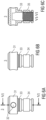
- FIG 1A shows sharpening guide 1 viewed from a side
- FIG 1B shows it viewed from above
- FIG 1C shows section I-I.
- Sharpening guide 1 comprises body 2 and top part 3, and bar 4, which assists the taking of the starting position of sharpening, is installed on top part 3, and bar 4 has reference end 400 and end 500 intended to face the user.
- end 500 of bar 4 intended to face the user there can be a ring, handle or similar.
- Bar 4 can have one or more limiters 42, such as o-rings.
- the purpose of limiter 42 is to prevent the unintentional removing of bar 4 from sharpening guide 1.
- bar 4 contains a number of alignment marks 41.
- Each alignment mark 41 corresponds to the starting position of sharpening accomplishable with the selected alignment mark, which starting position accomplishes the desired sharpening angle.
- Magnet 9 is advantageously located in recess 214 in magnet fastener 21 (cf. FIG 5A-5D ).
- Magnet fastener 21 is installed on body tube 22 (cf. FIG 3 ).
- Thread 25 and a counter thread in body tube 22 are arranged for height adjustment.
- FIG 4A shows a second embodiment of body tube 22, and FIG 4B shows its section IV-IV.
- Body tube 22 has an embossed surface in a similar manner as in a hand grenade for ensuring a better grip. This may be of advantage especially if the body tube is slippery to the hand, as may easily be the case in particular when the honing device is a water stone or oil stone.
- FIG 5A shows magnet fastener 21 viewed in a perspective
- FIG 5B shows it viewed from a side
- FIG 5C shows section V-V
- FIG 5D shows detail B.
- Thread 211 on the outer shell of fastener 21.
- Roughening 212 facilitates getting a better grip.
- Stopper 213 can come against body tube 22 when the height of sharpening guide 1 is adjusted to the shortest dimension.
- FIG 6A shows top part 3 without bar 4, from a first side, viewed perpendicularly relative to fastening hole 32 of the bar.
- FIG 6B shows same top part 3 without bar 4, from a second side (turned 90 degrees relative to the first side), viewed from the direction of fastening hole 32 of bar 4, and
- FIG 6C shows section VI-VI.
- Knob 31 comprises through-hole 32.
- Distance indicator 33 which can also be in the form of a roughening, most advantageously includes a scale, which can be in a spacing in mm (such as a spacing of 0.5 mm or 1 mm) or in a spacing in inches (such as a spacing of 1/16 or 1/8 inch).
- Top part 3 also comprises counter thread 35 for thread 35. Most advantageously, counter thread 35 is located inside body 34 of the top part. Body 34 can also comprise o-rings at the top and bottom.
- FIG 7A shows bar 4 viewed from above.
- FIG 7B shows section VII-VII.
- FIG 7C shows a second embodiment of bar 4 with 19.5 degrees and 16 degrees alignment marks.
- Bar 4 comprises a number of alignment marks 41 and possibly also limiter 42 or limiters, such as o-rings.
- FIG 7D shows the advantageous cross-section of bar 4, which cross-section is perpendicular (in other words transverse) relative to the longitudinal direction.
- FIG 8 shows different angles that are attainable by sharpening guide 1. Each of these is accomplished so that alignment mark 41 corresponding to each different angle causes, when bar 4 is at the alignment mark relative to blade line 101 of blade 100 to be sharpened, a different starting angle of sharpening between reference end 400 of bar 4 and honing device 99. This is illustrated below in connection with the description of FIG 13-18 .
- the position of bar 4 determines the angle relative to the front edge of blade 100 (blade line 101). When bar 4 is further out (in other words reference end 400 of bar 4 is father away from body 2 of sharpening guide 1), then the sharpening angle is gentler. When bar 4 less out (in other words reference end 400 of bar 4 is closer to body 2 of sharpening guide 1), then the sharpening angle is steeper.
- the generally used sharpening angles are 16, 18, 21, 23, 25, 27 degrees (+-1 degree).
- the sharpening of a microchamfer can also be carried out with the sharpening guide.
- bar 4 is first moved outwards, to a position of 23 degrees, for example. After this, blade 100 is sharpened. Finally, bar 4 is moved inwards, to a position of 21 degrees, for example. After this, blade 100 is swept a few times against honing device 99.
- FIG 9-11 show height adjustment of sharpening guide 1, used for compensating for the thickness of the blade to be sharpened.
- sharpening guide 1 is in its shortest configuration, and in FIG 10 it is in its longest configuration.
- FIG 9 shows sharpening guide 1 in the intermediate position.
- Thread 211 and counter thread 35 accomplish a change in the height of body 2 (in other words, the distance between bar 4 and magnet 9 changes), and by means of distance indicator 33 it is possible to visually verify that the desired height has been accomplished. An even easier way to ensure that the desired height is accomplished is to count the opening or closing revolutions (such as 0.5 mm per revolution).
- the compensation is: the thread is opened 7 revolutions from the closed position, in other words, bar 4 is lifted 3.5 mm.
- turning to the closed position relative to body 2 (rise of bar 0 mm by means of the sharpening device or in an alternative approach calculated from the maximum adjusting margin of 4 mm.
- a thinner blade (such as a sheath knife) is compensated for by turning a maximum of 8 revolutions/4 mm towards the open direction (the distance of bar 4 from the blade to be sharpened increases by means of sharpening guide 1).
- a rise of 4 mm is usually a suitable amount of compensation for a chisel, when the one-sided blade of a chisel requires a compensation of 4 mm.
- sharpening guide 1 comprises body 2 equipped with magnet 9 at its base, where elongated bar 4 is installed in top part 3 of body 2, which elongated bar 4 extends through top part 3, whereby sharpening guide 1 can be fastened on blade 100 to be sharpened by means of magnet 9 so that bar 4 forms an essentially right angle relative to blade line 101 when reference end 400 of bar 4 touches honing device 99.
- Bar 4 is movable relative to top part 3, whereby the starting angle of sharpening provided by sharpening guide 1 is adjustable by adjusting the length of the protruding part of bar 4 (in other words the distance between reference end 400 and body 2).
- At least two alignment marks 41 whereby, to change the starting angle, the position of bar 4 relative to body 2 is shifted and sharpening guide 1 is positioned relative to blade 100 to be sharpened so that second alignment mark 41 indicating the desired sharpening angle comes at blade line 101 of blade 100 to be sharpened.
- One end of bar 4 is end 500 intended to face the user.
- said at least one alignment mark 41 is on bar 4 between body 2 and reference end 400.
- Bar 4 most advantageously has a coding, such as a cut or notch, which corresponds to alignment marks 41, to facilitate adjustment.
- the height of body 2 is adjustable, whereby when the distance between top part 3 and magnet 9 changes, the distance between magnet 9 and bar 4 also changes.
- Body 2 and top part 3 are connected to each other by means of thread 25 so that the angle of pitch of thread 25 remains constant.
- loading spring 24 between body 2 and top part 3, which loading spring 24 loads bar 4 to prevent unintentional movement of bar 4.
- FIG 13-17 show the sharpening of a knife with a curved blade. It has been difficult to carry out the controlled sharpening of a curved blade by using currently available sharpening devices. Sharpening guide 1 according to the invention facilitates this considerably. By means of sharpening guide 1, it is possible to specify an exact starting angle in the sharpening of curved blade 100. The exact starting angle is specified most advantageously so that by means of sharpening guide 1, it is possible to increase the blade angle, or make the blade angle steeper steplessly during the sharpening movement after the starting angle / most gentle blade angle - in other words enabling the sharpening of a blade where the blade line is curved.
- FIG 13 and 14 show the starting of sharpening (stage I).
- Blade 100 to be sharpened in the example a sheath knife with curved blade
- Magnet 9 is fastened to blade 100 to be sharpened.
- Alignment mark 41 is placed so that it is vertical on top of blade line 101.
- Blade line 101 is most advantageously at a right angle relative to the longitudinal direction of honing device 99.
- FIG 15 and 16 show the final part of a sharpening sweep (stage II).
- Blade 100 to be sharpened has been drawn on honing device 99, with the blade line following this.
- Blade line 101 is most advantageously kept at a right angle relative to the longitudinal direction of honing device 99 throughout the draw.
- the blade can be pressed downwards during a draw, whereby bar 4 comes off from the surface of honing device 4 over distance d.
- FIG 17 shows a draw
- the distance of bar 4 is adjusted to conform to the desired angle.
- the height of body 2 is also adjusted to conform to the thickness of blade 100 (whereby the distance of bar 4 from magnet 9 changes).
- honing devices of the same thickness such as honing stones
- riser with the thickness of the honing device available
- bar 4 can be moved to the side of the other honing device (the one further at the back) or to the side of the riser, and blade 100 can be kept on the side of the honing device at the front, enabling the use of the entire length of the honing device.
- FIG 18 shows the sharpening of straight chisel blade 100.
- magnet 9 When magnet 9 is in contact with chisel blade 100, it has been necessary to increase the length of body 2 by turning 8 revolutions, because the one-sided chisel blade has not lifted the sharpening device upwards (in other words there has not been a need to perform downward compensation (turning towards the closed position)).
- body 2 has risen 0.5 mm per revolution, in other words a total of 4 mm. 4 mm of the thread, roughening or distance indicator 33 is visible.
Landscapes
- Engineering & Computer Science (AREA)
- Mechanical Engineering (AREA)
- Finish Polishing, Edge Sharpening, And Grinding By Specific Grinding Devices (AREA)
Abstract
Description
- The invention is related to sharpening guides, namely such that are used to guide a tool blade when starting sharpening or during sharpening. The sharpening guide is most advantageously used for sharpening tools such as chisels, plane cutters, knives, scissors and similar.
- During sharpening, the tool blade to be sharpened is moved relative to the sharpening device, such as emery paper, carbide stone, oil stone, water stone or similar. In this case, the goal is to keep the angle between the tool blade and the sharpening device constant when starting sharpening. If there is a need to create a microchamfer in the blade, then after the actual chamfer has been sharpened, the sharpening angle is increased by a few (usually 2 to 5) degrees, and the tip part of the actual chamfer is sharpened to the increased sharpening angle.
- Various types of blade guides are already known. As an example, Lie-Nielsen Toolworks, Inc sells a honing guide, a more detailed description of which can be found at the time of writing of this at: https://www.lie-nielsen.com/products/honing-guide-bladesstandard?path=sharpening-tool-care&node=4115. In order to adjust the correct blade angle in such a sharpening guide, a chisel or plane cutter, for example, must be set to extend over a certain distance beyond the sharpening guide. Curved blades cannot be sharpened with such a device, at least not easily, which makes it difficult or even impossible to sharpen, for example, chisels, plane cutters or knives with a curved blade.
- The objective of the invention is a sharpening guide with which the starting angle of sharpening can be made constant and with which especially curved blades can be sharpened easily. The sharpening guide also makes it easier to sharpen chisel blades or plane cutters, among others, to be convex.
- This objective can be accomplished by means of the sharpening guide according to
claim 1. - The dependent claims describe the advantageous aspects of the sharpening guide.
- The sharpening guide according to the invention comprises a body equipped with a magnet at its base, where an elongated bar is installed in the top part of the body, which elongated bar extends through the top part, whereby the sharpening guide can be placed on top of the blade to be sharpened by means of the magnet so that the bar forms an essentially right angle relative to the blade line when the reference end of the bar touches the surface of the honing device against which the blade to be sharpened is swept.
- By means of the sharpening guide it is easy to accomplish the desired constant angle at the beginning of sharpening between the blade to be sharpened and the sharpening device. This makes it easier to sharpen especially curved blades, such as sheath knives or chisels with curved blades, but it also enables easy sharpening of straight blades.
- According to an advantageous aspect, the bar is movable relative to the top part, whereby the starting angle of sharpening provided by the sharpening guide is adjustable by adjusting the length of the protruding part of the bar. This enables the adjustment of the starting angle of sharpening in an easy manner. In this way, for example, it is easily possible to sharpen a plane cutter to the desired angle, or the starting angle of sharpening can be exactly as desired.
- According to an advantageous aspect, the bar comprises at least one alignment mark, whereby the sharpening guide can also be positioned by means of the magnet so that the sharpening guide is aligned relative to the blade to be sharpened so that said alignment mark comes at the blade line of the blade to be sharpened, above it. This makes it possible to visually verify the starting angle of sharpening.
- In this case, there are most preferably at least two alignment marks, whereby, to change the starting angle, the position of the bar relative to the body is shifted and the sharpening guide is aligned relative to the blade to be sharpened so that the second alignment mark indicating the desired sharpening angle comes at the blade line of the blade to be sharpened.
- One end of the bar is most advantageously the reference end and the other end is the end intended to face the user. In the operation position of the sharpening guide, said at least one alignment mark is on the bar between the body and the reference end. In such a case, the bar most advantageously comprises a handle or holding part, such as a ring, fastened to the end intended to face the user. This intuitively helps to avoid an incorrect way of use, in other words that the user would attempt to position that end of the bar, which is intended to face the user, at the blade line of the blade to be sharpened.
- The bar most preferably has a coding, such as a cut or notch, which corresponds to the alignment marks, to facilitate adjustment. The coding can be at the alignment mark.
- According to a preferred aspect, the height of the body is adjustable, whereby when the distance between the top part and the magnet changes, the distance between the magnet and the bar also changes. This makes it possible to sharpen blades of different thicknesses to the same angle, when the distance between the top part and the magnet is adjusted on the basis of the thickness of the blade so that the angle is constant. In practice, the distance must be changed essentially by half of the change in the thickness of the blade.
- When the body and the top part are connected to each other by means of a thread so that the angle of pitch of the thread remains constant, the above-mentioned adjustment of the starting angle when sharpening blades of different thicknesses can be carried out steplessly using relatively simple technical means. Especially advantageously, an easily memorable angle of pitch can be chosen for the thread, such as 1/4, 1/2 mm or 1 mm per revolution (or, correspondingly, in countries using an inch size, for example, 1/16, 1/8 inch per revolution).
- According to a preferred aspect, there is a loading spring between the body and the top part, which loading spring loads the bar to prevent unintentional movement of the bar. This improves the end result of sharpening by keeping the starting angle constant.
- The sharpening guide and its preferred embodiments are presented in more detail in the detailed description by means of the embodiments presented in the attached drawing sheets
FIG 1-18 . Of the drawings: - FIG 1A
- shows the sharpening guide viewed from a side;
- FIG 1B
- shows the sharpening guide shown in
FIG 1A viewed from above; - FIG 1C
- shows section I-I of the sharpening guide (see
FIG 1B ); - FIG 2
- shows the spring loading spring of the bar;
- FIG 3
- shows one embodiment of the body tube;
- FIG 4A
- shows a second embodiment of the body tube;
- FIG 4B
- shows section IV-IV of the body tube shown in
FIG 4A ; - FIG 5A
- shows a fastener of the magnet viewed in a perspective;
- FIG 5B
- shows the fastener of the magnet shown in
FIG 5A viewed from a side; - FIG 5C
- shows section V-V of the fastener of the magnet shown in
FIG 5B ; - FIG 5D
- shows detail B;
- FIG 6A
- shows the top part without the bar, from a first side, viewed perpendicularly relative to the fastening hole of the bar;
- FIG 6B
- shows the top part without the bar shown in
FIG 6A , from a second side (turned 90 degrees relative to the first side), viewed from the direction of the fastening hole of the bar; - FIG 6C
- shows section VI-VI (see
FIG 6A ); - FIG 7A
- shows the bar viewed from above;
- FIG 7B
- shows section VII-VII (see
FIG 7A ); - FIG 7C
- shows an embodiment of the bar with 19.5 degrees and 16 degrees alignment marks;
- FIG 7D
- shows a transverse cross-section of the bar;
- FIG 8
- shows the blade angles attainable by means of the bar;
- FIG 9
- shows the sharpening guide in the intermediate position of the body height;
- FIG 10
- shows the sharpening guide in the top position of the body height;
- FIG 11
- shows the sharpening guide in the bottom position of the body height;
- FIG 12
- shows the adjustment of the body height;
- FIG 13 - 17
- show the sharpening of a knife with curved blade; and
- FIG 18
- shows the sharpening of a chisel with straight blade.
- The same reference numbers refer to the same structural parts in all FIG.
-
FIG 1A shows sharpeningguide 1 viewed from a side,FIG 1B shows it viewed from above, andFIG 1C shows section I-I. Sharpeningguide 1 comprisesbody 2 andtop part 3, andbar 4, which assists the taking of the starting position of sharpening, is installed ontop part 3, andbar 4 hasreference end 400 and end 500 intended to face the user. Atend 500 ofbar 4 intended to face the user, there can be a ring, handle or similar. -
Bar 4 can have one ormore limiters 42, such as o-rings. The purpose oflimiter 42 is to prevent the unintentional removing ofbar 4 from sharpeningguide 1. In addition to this,bar 4 contains a number of alignment marks 41. Eachalignment mark 41 corresponds to the starting position of sharpening accomplishable with the selected alignment mark, which starting position accomplishes the desired sharpening angle. -
Magnet 9 is advantageously located inrecess 214 in magnet fastener 21 (cf.FIG 5A-5D ).Magnet fastener 21 is installed on body tube 22 (cf.FIG 3 ).Thread 25 and a counter thread inbody tube 22 are arranged for height adjustment.Spring 24 betweenbar 4 and magnet fastener 21 (cf.FIG 2 ) spring loads bar 4. -
FIG 4A shows a second embodiment ofbody tube 22, andFIG 4B shows its section IV-IV.Body tube 22 has an embossed surface in a similar manner as in a hand grenade for ensuring a better grip. This may be of advantage especially if the body tube is slippery to the hand, as may easily be the case in particular when the honing device is a water stone or oil stone. -
FIG 5A showsmagnet fastener 21 viewed in a perspective, andFIG 5B shows it viewed from a side.FIG 5C shows section V-V, andFIG 5D shows detail B. There isthread 211 on the outer shell offastener 21.Roughening 212 facilitates getting a better grip.Stopper 213 can come againstbody tube 22 when the height of sharpeningguide 1 is adjusted to the shortest dimension. -
FIG 6A showstop part 3 withoutbar 4, from a first side, viewed perpendicularly relative tofastening hole 32 of the bar.FIG 6B shows sametop part 3 withoutbar 4, from a second side (turned 90 degrees relative to the first side), viewed from the direction offastening hole 32 ofbar 4, andFIG 6C shows section VI-VI.Knob 31 comprises through-hole 32.Distance indicator 33, which can also be in the form of a roughening, most advantageously includes a scale, which can be in a spacing in mm (such as a spacing of 0.5 mm or 1 mm) or in a spacing in inches (such as a spacing of 1/16 or 1/8 inch).Top part 3 also comprisescounter thread 35 forthread 35. Most advantageously,counter thread 35 is located insidebody 34 of the top part.Body 34 can also comprise o-rings at the top and bottom. -
FIG 7A showsbar 4 viewed from above.FIG 7B shows section VII-VII.FIG 7C shows a second embodiment ofbar 4 with 19.5 degrees and 16 degrees alignment marks.Bar 4 comprises a number of alignment marks 41 and possibly also limiter 42 or limiters, such as o-rings.FIG 7D shows the advantageous cross-section ofbar 4, which cross-section is perpendicular (in other words transverse) relative to the longitudinal direction. -
FIG 8 shows different angles that are attainable by sharpeningguide 1. Each of these is accomplished so thatalignment mark 41 corresponding to each different angle causes, whenbar 4 is at the alignment mark relative toblade line 101 ofblade 100 to be sharpened, a different starting angle of sharpening betweenreference end 400 ofbar 4 and honingdevice 99. This is illustrated below in connection with the description ofFIG 13-18 . - There is no limit to the width of
blades 100 to be sharpened. - The position of
bar 4 determines the angle relative to the front edge of blade 100 (blade line 101). Whenbar 4 is further out (in other words reference end 400 ofbar 4 is father away frombody 2 of sharpening guide 1), then the sharpening angle is gentler. Whenbar 4 less out (in other words reference end 400 ofbar 4 is closer tobody 2 of sharpening guide 1), then the sharpening angle is steeper. - The generally used sharpening angles are 16, 18, 21, 23, 25, 27 degrees (+-1 degree).
- The sharpening of a microchamfer can also be carried out with the sharpening guide. In this case,
bar 4 is first moved outwards, to a position of 23 degrees, for example. After this,blade 100 is sharpened. Finally,bar 4 is moved inwards, to a position of 21 degrees, for example. After this,blade 100 is swept a few times against honingdevice 99. -
FIG 9-11 show height adjustment of sharpeningguide 1, used for compensating for the thickness of the blade to be sharpened. InFIG 11 , sharpeningguide 1 is in its shortest configuration, and inFIG 10 it is in its longest configuration.FIG 9 shows sharpening guide 1 in the intermediate position. - Height adjustment most advantageously takes place in the manner shown in
FIG 12 by rotatingbar 4, wherebytop part 3 rotates relative tobody 2, in other words also relative tomagnet fastener 212 andmagnet 9.Thread 211 andcounter thread 35 accomplish a change in the height of body 2 (in other words, the distance betweenbar 4 andmagnet 9 changes), and by means ofdistance indicator 33 it is possible to visually verify that the desired height has been accomplished. An even easier way to ensure that the desired height is accomplished is to count the opening or closing revolutions (such as 0.5 mm per revolution). - As an example, if the blade to be sharpened is 1 mm thick, the compensation is: the thread is opened 7 revolutions from the closed position, in other words,
bar 4 is lifted 3.5 mm. - Example: A survival sheath knife where the thickness of the blade is 8 mm. In this case, turning to the closed position relative to body 2 (rise of bar 0 mm by means of the sharpening device or in an alternative approach calculated from the maximum adjusting margin of 4 mm.
- Example: A thicker blade (such as a sheath knife) is compensated for by turning towards the closed position (in sharpening
guide 1 the distance gets smaller, in other words, the distance brought by the thickness of the blade of the knife to the bar is compensated for). A thinner blade (such as a sheath knife) is compensated for by turning a maximum of 8 revolutions/4 mm towards the open direction (the distance ofbar 4 from the blade to be sharpened increases by means of sharpening guide 1). - As an example, a rise of 4 mm is usually a suitable amount of compensation for a chisel, when the one-sided blade of a chisel requires a compensation of 4 mm.
- In other words, sharpening
guide 1 comprisesbody 2 equipped withmagnet 9 at its base, whereelongated bar 4 is installed intop part 3 ofbody 2, which elongatedbar 4 extends throughtop part 3, whereby sharpeningguide 1 can be fastened onblade 100 to be sharpened by means ofmagnet 9 so thatbar 4 forms an essentially right angle relative toblade line 101 whenreference end 400 ofbar 4touches honing device 99. -
Bar 4 is movable relative totop part 3, whereby the starting angle of sharpening provided by sharpeningguide 1 is adjustable by adjusting the length of the protruding part of bar 4 (in other words the distance betweenreference end 400 and body 2). -
Bar 4 comprises at least onealignment mark 41, whereby sharpeningguide 1 can also be positioned by means ofmagnet 9 so that the sharpening guide is positioned relative to the blade to be sharpened so that saidalignment mark 41 comes atblade line 101 ofblade 100 to be sharpened, above it. - There are most advantageously at least two alignment marks 41, whereby, to change the starting angle, the position of
bar 4 relative tobody 2 is shifted and sharpeningguide 1 is positioned relative toblade 100 to be sharpened so thatsecond alignment mark 41 indicating the desired sharpening angle comes atblade line 101 ofblade 100 to be sharpened. - One end of
bar 4 is end 500 intended to face the user. In the operation position of sharpeningguide 1, said at least onealignment mark 41 is onbar 4 betweenbody 2 andreference end 400. -
Bar 4 comprises handle or holdingpart 5, such as a ring, fastened to end 500 intended to face the user. -
Bar 4 most advantageously has a coding, such as a cut or notch, which corresponds to alignment marks 41, to facilitate adjustment. - The height of
body 2 is adjustable, whereby when the distance betweentop part 3 andmagnet 9 changes, the distance betweenmagnet 9 andbar 4 also changes. -
Body 2 andtop part 3 are connected to each other by means ofthread 25 so that the angle of pitch ofthread 25 remains constant. - There is loading
spring 24 betweenbody 2 andtop part 3, whichloading spring 24 loads bar 4 to prevent unintentional movement ofbar 4. -
FIG 13-17 show the sharpening of a knife with a curved blade. It has been difficult to carry out the controlled sharpening of a curved blade by using currently available sharpening devices. Sharpeningguide 1 according to the invention facilitates this considerably. By means of sharpeningguide 1, it is possible to specify an exact starting angle in the sharpening ofcurved blade 100. The exact starting angle is specified most advantageously so that by means of sharpeningguide 1, it is possible to increase the blade angle, or make the blade angle steeper steplessly during the sharpening movement after the starting angle / most gentle blade angle - in other words enabling the sharpening of a blade where the blade line is curved. -
FIG 13 and14 show the starting of sharpening (stage I).Blade 100 to be sharpened (in the example a sheath knife with curved blade) lies on top of honingdevice 99.Magnet 9 is fastened toblade 100 to be sharpened.Alignment mark 41 is placed so that it is vertical on top ofblade line 101.Blade line 101 is most advantageously at a right angle relative to the longitudinal direction of honingdevice 99. -
FIG 15 and16 show the final part of a sharpening sweep (stage II).Blade 100 to be sharpened has been drawn on honingdevice 99, with the blade line following this.Blade line 101 is most advantageously kept at a right angle relative to the longitudinal direction of honingdevice 99 throughout the draw. The blade can be pressed downwards during a draw, wherebybar 4 comes off from the surface of honingdevice 4 over distance d. -
FIG 17 shows a draw. - In practice, when
blade 100 of a sheath knife or other tool is sharpened, the distance ofbar 4 is adjusted to conform to the desired angle. The height ofbody 2 is also adjusted to conform to the thickness of blade 100 (whereby the distance ofbar 4 frommagnet 9 changes). - When the blade is pulled backwards and pressed down, the angle decreases by a few degrees, whereby
bar 4 comes off from the surface of the honing device over distance d. - If there are honing devices of the same thickness (such as honing stones) available or if there is a riser with the thickness of the honing device available, they can be placed one after the other. In this case,
bar 4 can be moved to the side of the other honing device (the one further at the back) or to the side of the riser, andblade 100 can be kept on the side of the honing device at the front, enabling the use of the entire length of the honing device. -
FIG 18 shows the sharpening ofstraight chisel blade 100. Whenmagnet 9 is in contact withchisel blade 100, it has been necessary to increase the length ofbody 2 by turning 8 revolutions, because the one-sided chisel blade has not lifted the sharpening device upwards (in other words there has not been a need to perform downward compensation (turning towards the closed position)). In this case,body 2 has risen 0.5 mm per revolution, in other words a total of 4 mm. 4 mm of the thread, roughening ordistance indicator 33 is visible. - The invention should not be understood to be limited only by the below claims, but the invention is to be understood to include all their legal equivalents and the combinations of the embodiments presented.
-
- 1
- sharpening guide
- 2
- body
- 3
- top part
- 4
- bar
- 5
- ring
- 9
- magnet
- 21
- magnet fastener
- 22
- body tube (customisable, of hard plastic, of metal)
- 24
- spring
- 25
- thread
- 31
- knob
- 32
- through-hole/hole
- 33
- distance indicator
- 34
- top part body
- 35
- counter thread for
thread 211 - 41
- alignment mark
- 42
- bar limiter, e.g. o-ring
- 99
- honing device
- 100
- blade
- 101
- blade line
- 211
- thread that attaches to
thread 35 - 212
- roughening into which glue is applied so that it stays in place in
body tube 22 - 213
-
body tube 22 stopper - 214
- magnet recess
- 215
- magnet recess (recess with counter thread)
- 400
- reference end of bar
- 500
- end of bar intended to face the user
Claims (10)
- A sharpening guide (1) for the sharpening of a tool blade (100), comprising: a body (2) equipped with a magnet (9) at its base, where an elongated bar (4) is installed in the top part (3) of the body (2), which elongated bar (4) extends through the top part (3), whereby the sharpening guide (1) can be fastened on the blade (100) to be sharpened by means of the magnet (9) so that the bar (4) forms an essentially right angle relative to the blade line (101) when a reference end (400) of the bar (4) touches the surface of a honing device (99) against which the blade to be sharpened is swept.
- The sharpening guide (1) according to claim 1, where: the bar (4) is movable relative to the top part (3), whereby the starting angle of sharpening provided by the sharpening guide (1) is adjustable by adjusting the length of the protruding part of the bar (4).
- The sharpening guide (1) according to claim 1 or 2, where: the bar (4) comprises at least one alignment mark (41), whereby the sharpening guide (1) can also be set by means of the magnet (9) so that the sharpening guide is aligned relative to the blade to be sharpened so that said alignment mark (41) comes at the blade line (101) of the blade (100) to be sharpened, directly above it.
- The sharpening guide (1) according to claim 3, where: there are at least two alignment marks (41), whereby, to change the starting angle, the position of the bar (4) relative to the body (2) is shifted and the sharpening guide (1) is aligned relative to the blade to be sharpened so that the second alignment mark (41) indicating the desired sharpening angle comes at the blade line (101) of the blade (100) to be sharpened.
- The sharpening guide (1) according to claim 3 or 4, where: one end of the bar (4) is an end (500) intended to face the user, and where said at least one alignment mark (41) is in the operation position of the sharpening guide (1) on the bar (4) between the body (2) and the reference end (400).
- The sharpening guide (1) according to claim 5, where: the bar (4) comprises a handle or holding part (5), such as a ring, fastened to the end (500) intended to face the user.
- The sharpening guide (1) according to any one of the claims 3-6, where: the bar (4) has a coding, such as a cut or notch, which corresponds to the alignment marks (41), to facilitate adjustment.
- The sharpening guide (1) according to any one of the preceding claims 1-7, where: the height of the body (2) is adjustable, whereby when the distance between the top part (3) and the magnet (9) changes, the distance between the magnet (9) and the bar (4) also changes.
- The sharpening guide (1) according to claim 8, where: the body (2) and the top part (3) are connected to each other by means of a thread (25) so that the angle of pitch of the thread (25) remains constant.
- The sharpening guide (1) according to any one of the preceding claims, where: there is a loading spring (24) between the body (2) and the top part (3), which loading spring (24) loads the bar (4) to prevent unintentional movement of the bar (4).
Applications Claiming Priority (1)
| Application Number | Priority Date | Filing Date | Title |
|---|---|---|---|
| FI20235047 | 2023-01-18 |
Publications (3)
| Publication Number | Publication Date |
|---|---|
| EP4403303A1 true EP4403303A1 (en) | 2024-07-24 |
| EP4403303C0 EP4403303C0 (en) | 2025-10-08 |
| EP4403303B1 EP4403303B1 (en) | 2025-10-08 |
Family
ID=88647298
Family Applications (1)
| Application Number | Title | Priority Date | Filing Date |
|---|---|---|---|
| EP23206876.7A Active EP4403303B1 (en) | 2023-01-18 | 2023-10-31 | Sharpening guide |
Country Status (1)
| Country | Link |
|---|---|
| EP (1) | EP4403303B1 (en) |
Citations (3)
| Publication number | Priority date | Publication date | Assignee | Title |
|---|---|---|---|---|
| US7874896B1 (en) * | 2006-10-12 | 2011-01-25 | Vogel Capital Inc. | Sharpening guide assembly |
| US20110159791A1 (en) * | 2009-12-30 | 2011-06-30 | Wu Heng | Blade Sharpening Assembly |
| WO2022038594A1 (en) * | 2020-08-19 | 2022-02-24 | Alex Gontmakher | A blade sharpening system |
-
2023
- 2023-10-31 EP EP23206876.7A patent/EP4403303B1/en active Active
Patent Citations (3)
| Publication number | Priority date | Publication date | Assignee | Title |
|---|---|---|---|---|
| US7874896B1 (en) * | 2006-10-12 | 2011-01-25 | Vogel Capital Inc. | Sharpening guide assembly |
| US20110159791A1 (en) * | 2009-12-30 | 2011-06-30 | Wu Heng | Blade Sharpening Assembly |
| WO2022038594A1 (en) * | 2020-08-19 | 2022-02-24 | Alex Gontmakher | A blade sharpening system |
Also Published As
| Publication number | Publication date |
|---|---|
| EP4403303C0 (en) | 2025-10-08 |
| EP4403303B1 (en) | 2025-10-08 |
Similar Documents
| Publication | Publication Date | Title |
|---|---|---|
| US6997795B2 (en) | Versatile manual scissor sharpener | |
| US6578268B2 (en) | Tool | |
| NZ229623A (en) | Blade sharpener with clamp | |
| US3233643A (en) | Shingling hatchet | |
| US7549910B2 (en) | Blade sharpening holder | |
| GB2113138A (en) | Instrument for making corneal incisions | |
| US2324025A (en) | Dental tool grinder | |
| US7959494B1 (en) | Sharpening cutting blades having a progressively changing cutting angle | |
| US11648797B2 (en) | Carpenter speed square with pencil sharpener | |
| US20110225831A1 (en) | Rotary Knife For Drywall and the Like | |
| EP4403303B1 (en) | Sharpening guide | |
| EP0291768B1 (en) | Carpet seam cutter | |
| US4440045A (en) | Chain saw sharpener | |
| US5431070A (en) | Adjustable knife blade guide | |
| US8070563B2 (en) | Whet-stone receptacle and hand guard | |
| US5184425A (en) | Drill bit sharpener | |
| US5241791A (en) | Edge tool sharpening apparatus | |
| US4541176A (en) | Glass cutter and accessory | |
| US5377413A (en) | Retracting cutter | |
| US4345631A (en) | Wood turning tool | |
| US1630182A (en) | Razor-honing device | |
| US2559987A (en) | Groove cutting or inletting tool | |
| US302496A (en) | Tool-holder | |
| US755248A (en) | Device for grooving or tapping rubber or other sap-yielding trees. | |
| US2155175A (en) | Honing device for shears |
Legal Events
| Date | Code | Title | Description |
|---|---|---|---|
| PUAI | Public reference made under article 153(3) epc to a published international application that has entered the european phase |
Free format text: ORIGINAL CODE: 0009012 |
|
| STAA | Information on the status of an ep patent application or granted ep patent |
Free format text: STATUS: THE APPLICATION HAS BEEN PUBLISHED |
|
| AK | Designated contracting states |
Kind code of ref document: A1 Designated state(s): AL AT BE BG CH CY CZ DE DK EE ES FI FR GB GR HR HU IE IS IT LI LT LU LV MC ME MK MT NL NO PL PT RO RS SE SI SK SM TR |
|
| STAA | Information on the status of an ep patent application or granted ep patent |
Free format text: STATUS: REQUEST FOR EXAMINATION WAS MADE |
|
| 17P | Request for examination filed |
Effective date: 20250113 |
|
| GRAP | Despatch of communication of intention to grant a patent |
Free format text: ORIGINAL CODE: EPIDOSNIGR1 |
|
| STAA | Information on the status of an ep patent application or granted ep patent |
Free format text: STATUS: GRANT OF PATENT IS INTENDED |
|
| GRAJ | Information related to disapproval of communication of intention to grant by the applicant or resumption of examination proceedings by the epo deleted |
Free format text: ORIGINAL CODE: EPIDOSDIGR1 |
|
| STAA | Information on the status of an ep patent application or granted ep patent |
Free format text: STATUS: REQUEST FOR EXAMINATION WAS MADE |
|
| INTG | Intention to grant announced |
Effective date: 20250610 |
|
| GRAP | Despatch of communication of intention to grant a patent |
Free format text: ORIGINAL CODE: EPIDOSNIGR1 |
|
| STAA | Information on the status of an ep patent application or granted ep patent |
Free format text: STATUS: GRANT OF PATENT IS INTENDED |
|
| INTC | Intention to grant announced (deleted) | ||
| INTG | Intention to grant announced |
Effective date: 20250725 |
|
| GRAS | Grant fee paid |
Free format text: ORIGINAL CODE: EPIDOSNIGR3 |
|
| GRAA | (expected) grant |
Free format text: ORIGINAL CODE: 0009210 |
|
| STAA | Information on the status of an ep patent application or granted ep patent |
Free format text: STATUS: THE PATENT HAS BEEN GRANTED |
|
| AK | Designated contracting states |
Kind code of ref document: B1 Designated state(s): AL AT BE BG CH CY CZ DE DK EE ES FI FR GB GR HR HU IE IS IT LI LT LU LV MC ME MK MT NL NO PL PT RO RS SE SI SK SM TR |
|
| REG | Reference to a national code |
Ref country code: GB Ref legal event code: FG4D Ref country code: CH Ref legal event code: F10 Free format text: ST27 STATUS EVENT CODE: U-0-0-F10-F00 (AS PROVIDED BY THE NATIONAL OFFICE) Effective date: 20251008 |
|
| REG | Reference to a national code |
Ref country code: DE Ref legal event code: R096 Ref document number: 602023007296 Country of ref document: DE |
|
| REG | Reference to a national code |
Ref country code: IE Ref legal event code: FG4D |
|
| U01 | Request for unitary effect filed |
Effective date: 20251105 |
|
| U07 | Unitary effect registered |
Designated state(s): AT BE BG DE DK EE FI FR IT LT LU LV MT NL PT RO SE SI Effective date: 20251111 |
|
| U20 | Renewal fee for the european patent with unitary effect paid |
Year of fee payment: 3 Effective date: 20251106 |
|
| PG25 | Lapsed in a contracting state [announced via postgrant information from national office to epo] |
Ref country code: ES Free format text: LAPSE BECAUSE OF FAILURE TO SUBMIT A TRANSLATION OF THE DESCRIPTION OR TO PAY THE FEE WITHIN THE PRESCRIBED TIME-LIMIT Effective date: 20251008 |
|
| PG25 | Lapsed in a contracting state [announced via postgrant information from national office to epo] |
Ref country code: NO Free format text: LAPSE BECAUSE OF FAILURE TO SUBMIT A TRANSLATION OF THE DESCRIPTION OR TO PAY THE FEE WITHIN THE PRESCRIBED TIME-LIMIT Effective date: 20260108 |
|
| PG25 | Lapsed in a contracting state [announced via postgrant information from national office to epo] |
Ref country code: HR Free format text: LAPSE BECAUSE OF FAILURE TO SUBMIT A TRANSLATION OF THE DESCRIPTION OR TO PAY THE FEE WITHIN THE PRESCRIBED TIME-LIMIT Effective date: 20251008 |
|
| PG25 | Lapsed in a contracting state [announced via postgrant information from national office to epo] |
Ref country code: RS Free format text: LAPSE BECAUSE OF FAILURE TO SUBMIT A TRANSLATION OF THE DESCRIPTION OR TO PAY THE FEE WITHIN THE PRESCRIBED TIME-LIMIT Effective date: 20260108 |
|
| PG25 | Lapsed in a contracting state [announced via postgrant information from national office to epo] |
Ref country code: IS Free format text: LAPSE BECAUSE OF FAILURE TO SUBMIT A TRANSLATION OF THE DESCRIPTION OR TO PAY THE FEE WITHIN THE PRESCRIBED TIME-LIMIT Effective date: 20260208 |
|
| PG25 | Lapsed in a contracting state [announced via postgrant information from national office to epo] |
Ref country code: PL Free format text: LAPSE BECAUSE OF FAILURE TO SUBMIT A TRANSLATION OF THE DESCRIPTION OR TO PAY THE FEE WITHIN THE PRESCRIBED TIME-LIMIT Effective date: 20251008 |
|
| PG25 | Lapsed in a contracting state [announced via postgrant information from national office to epo] |
Ref country code: SM Free format text: LAPSE BECAUSE OF FAILURE TO SUBMIT A TRANSLATION OF THE DESCRIPTION OR TO PAY THE FEE WITHIN THE PRESCRIBED TIME-LIMIT Effective date: 20251008 |
|
| PG25 | Lapsed in a contracting state [announced via postgrant information from national office to epo] |
Ref country code: MC Free format text: LAPSE BECAUSE OF FAILURE TO SUBMIT A TRANSLATION OF THE DESCRIPTION OR TO PAY THE FEE WITHIN THE PRESCRIBED TIME-LIMIT Effective date: 20251008 |
|
| PG25 | Lapsed in a contracting state [announced via postgrant information from national office to epo] |
Ref country code: CZ Free format text: LAPSE BECAUSE OF FAILURE TO SUBMIT A TRANSLATION OF THE DESCRIPTION OR TO PAY THE FEE WITHIN THE PRESCRIBED TIME-LIMIT Effective date: 20251008 |
|
| PG25 | Lapsed in a contracting state [announced via postgrant information from national office to epo] |
Ref country code: SK Free format text: LAPSE BECAUSE OF FAILURE TO SUBMIT A TRANSLATION OF THE DESCRIPTION OR TO PAY THE FEE WITHIN THE PRESCRIBED TIME-LIMIT Effective date: 20251008 |
|
| PLBE | No opposition filed within time limit |
Free format text: ORIGINAL CODE: 0009261 |
|
| STAA | Information on the status of an ep patent application or granted ep patent |
Free format text: STATUS: NO OPPOSITION FILED WITHIN TIME LIMIT |