EP4403262B1 - Machine de traitement de roches dotée d'une évaluation d'usure et d'une évaluation qualitative de l'évaluation d'usure - Google Patents
Machine de traitement de roches dotée d'une évaluation d'usure et d'une évaluation qualitative de l'évaluation d'usure Download PDFInfo
- Publication number
- EP4403262B1 EP4403262B1 EP24151911.5A EP24151911A EP4403262B1 EP 4403262 B1 EP4403262 B1 EP 4403262B1 EP 24151911 A EP24151911 A EP 24151911A EP 4403262 B1 EP4403262 B1 EP 4403262B1
- Authority
- EP
- European Patent Office
- Prior art keywords
- wear
- data
- processing machine
- information
- rock
- Prior art date
- Legal status (The legal status is an assumption and is not a legal conclusion. Google has not performed a legal analysis and makes no representation as to the accuracy of the status listed.)
- Active
Links
Images


Classifications
-
- B—PERFORMING OPERATIONS; TRANSPORTING
- B02—CRUSHING, PULVERISING, OR DISINTEGRATING; PREPARATORY TREATMENT OF GRAIN FOR MILLING
- B02C—CRUSHING, PULVERISING, OR DISINTEGRATING IN GENERAL; MILLING GRAIN
- B02C21/00—Disintegrating plant with or without drying of the material
-
- B—PERFORMING OPERATIONS; TRANSPORTING
- B02—CRUSHING, PULVERISING, OR DISINTEGRATING; PREPARATORY TREATMENT OF GRAIN FOR MILLING
- B02C—CRUSHING, PULVERISING, OR DISINTEGRATING IN GENERAL; MILLING GRAIN
- B02C21/00—Disintegrating plant with or without drying of the material
- B02C21/02—Transportable disintegrating plant
- B02C21/026—Transportable disintegrating plant self-propelled
-
- B—PERFORMING OPERATIONS; TRANSPORTING
- B02—CRUSHING, PULVERISING, OR DISINTEGRATING; PREPARATORY TREATMENT OF GRAIN FOR MILLING
- B02C—CRUSHING, PULVERISING, OR DISINTEGRATING IN GENERAL; MILLING GRAIN
- B02C23/00—Auxiliary methods or auxiliary devices or accessories specially adapted for crushing or disintegrating not provided for in preceding groups or not specially adapted to apparatus covered by a single preceding group
- B02C23/08—Separating or sorting of material, associated with crushing or disintegrating
-
- B—PERFORMING OPERATIONS; TRANSPORTING
- B02—CRUSHING, PULVERISING, OR DISINTEGRATING; PREPARATORY TREATMENT OF GRAIN FOR MILLING
- B02C—CRUSHING, PULVERISING, OR DISINTEGRATING IN GENERAL; MILLING GRAIN
- B02C25/00—Control arrangements specially adapted for crushing or disintegrating
-
- B—PERFORMING OPERATIONS; TRANSPORTING
- B02—CRUSHING, PULVERISING, OR DISINTEGRATING; PREPARATORY TREATMENT OF GRAIN FOR MILLING
- B02C—CRUSHING, PULVERISING, OR DISINTEGRATING IN GENERAL; MILLING GRAIN
- B02C2210/00—Codes relating to different types of disintegrating devices
- B02C2210/01—Indication of wear on beaters, knives, rollers, anvils, linings and the like
Definitions
- Such a generic rock processing machine which includes the data processing device as a machine component, is known from WO 2008/- 021040 A1 known.
- rock processing machines Due to their physical and abrasive interaction with mineral rock, rock processing machines are subject to above-average wear compared to other working machines. This applies in particular to crushing devices as working devices of a rock processing machine, which Unlike screening devices, these devices do not sort mineral rock solely based on their mesh size, utilizing a relative movement between the rock and the screening device. Instead, they use crushing tools to exert a force on the rock in the crushing device that exceeds the rock's intended breaking strength. This crushes the rock in the crushing device. As the rock is crushed in the crushing device, the number of rock grains in the rock processing machine, and in particular the crushing device, increases. As the number of rock grains increases, so does the number of wear-promoting sharp fracture edges in the rock processing machine.
- the service life of a working tool assembly i.e., the ability of a working tool assembly to perform work as intended from the initial use until the limit of its usability is reached, in rock processing machines is essentially exclusively dependent on wear.
- the wear limit of the working tool assembly is reached during operation of the rock processing machine before another event occurs that terminates the service life or usability of the working tool assembly. Therefore, for the proactive operation of a rock processing machine, determining the wear status of the working tool assembly is helpful in planning further operation and the remaining operating capacity until the next maintenance of the rock processing machine, thus achieving the highest possible productivity of the rock processing machine.
- the ones from the WO 2008/021040 A1 A known rock processing machine determines a wear model from historical wear data determined for the respective working tool arrangement and, based on this wear model, enables the operation-accompanying, selective determination of wear information and a wear prediction for the affected working tool arrangement.
- the data collection basis for the data used to determine the wear information is defined in the WO 2008/021040 A1 Comparative measurements of wear on identical working tool arrangements in previous intended use.
- the WO 2008/021040 A1 It also teaches measuring the residual thickness of the working tool arrangement remaining after a certain period of operation and comparing the measured residual thickness with historical wear data in order to select, based on the comparison, a historical data series that is particularly relevant for the particular application from several historical wear data sets, or to select historical wear data that is close in magnitude to the measured residual thickness and to interpolate a data series for the currently considered working tool arrangement from these data sets.
- the selected or interpolated data series then serves as the basis for calculating wear information about a presumably existing wear condition or a wear condition expected in the future.
- the WO 2008/021040 A1 further teaches how to determine a wear rate based on the initial strength of the working tool arrangement in a wear-free state, a residual strength measured at a point in time after a period of use and the period of use that has elapsed in the meantime, and how to calculate a residual capacity in the form of a residual service life based on the wear rate.
- WO 2008/021040 A1 Finally, it teaches how to compare the calculated wear rate with wear rates determined from historical wear data and, based on the result of the comparison of the wear rates, to change the operating parameters of the rock processing machine if necessary.
- Wear predictions determined in this way are, firstly, only possible if actual historical wear data is available. However, if this historical wear data is available, the specific numerical values obtained with the wear predictions often convey a false sense of certainty. Relying on the accuracy of the provided numerical values, which are in fact subject to uncertainty, predicted wear events may then occur earlier than expected, catching the machine operator unprepared despite the prediction or even causing damage to the machine. Or maintenance work may be initiated too early based on the predictions, thus underutilizing the work tool arrangement.
- the object of the present invention is to further develop a rock processing machine of the type mentioned above in such a way that the operator supplied with wear information via the output device can be informed about the quality of the determined wear information, in particular about its accuracy. Furthermore, it is desirable to enable the provision of wear information independent of the availability of historical wear data. In this case, it is especially helpful to provide the operator with an indication of the quality of the wear information.
- the present invention solves this problem in a rock processing machine of the type mentioned at the outset, in which the data processing device is further designed to determine quality information relating to a quality of the wear information for the determined wear information, based on at least one data collection basis on which at least part of the data used to determine the wear information is based, and to output said quality information by means of the output device.
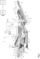
- the rock processing machine 12 has the following, based on the larger illustration of Figure 2 described machine components:
- the rock processing machine 12 comprises a control device 60, for example in the form of an electronic data processing device with integrated circuits, which controls the operation of machine components.
- the control device 60 can, for example, either directly control drives of machine components or control actuators, which in turn can move components.
- the rock processing machine 12 also has various sensors for obtaining information about its operating state, which are connected to the control device 60 and thus, in the example shown, indirectly to the data memory 62. For the sake of clarity, the sensors are only shown in Figure 2 shown.
- the wear condition of the impact crusher 14, the working device of the rock processing machine 12 can be determined as part of a zero-point determination typical for the type of rock processing machine 12 shown.
- a crushing gap width of zero is set in the upper and lower crushing gaps, i.e., the impact rockers 72 and 74 are moved until they physically abut the impact beams 75a (for clarity, only one impact beam is designated with the reference symbol "75a") of the central crushing rotor 75.
- the wear condition of the impact rockers 72 and 74 and the impact beams 75a in the crushing rotor 75 Based on the resulting wear-dependent rotational position of the impact rockers 72 and 74, quantitative and/or qualitative conclusions can be drawn regarding the wear condition of the impact rockers 72 and 74 and the impact beams 75a in the crushing rotor 75.
- a speed sensor 80 determines the speed of the crushing rotor of the impact crusher 14 and transmits it to the control device 60.
- a third belt scale 92 is arranged in the oversize grain conveyor 36 and determines the weight or mass of the oversize grain of the oversize grain fraction 34 conveyed above it on the oversize grain conveyor 36.
- a speed sensor 94 of a deflection roller of the conveyor belt of the oversize grain conveyor 36 determines the conveying speed of the oversize grain conveyor 36 and transmits this to the control device 60, which, in conjunction with the detection signals of the third belt scale 92, can determine a conveying capacity of the oversize grain conveyor.
- a first stockpile sensor 96 is arranged, which acts as a camera to capture images of the fine grain stockpile 44 and transmits it as image information to a control device 60.
- the control device detects contours of the fine grain stockpile 48 through image processing and, based on the known image data from the camera of the first stockpile sensor 96, determines a shape and, from this, a volume of the fine grain stockpile 48 based on the detected contours.
- the control device 60 can, without excessive error, assume an ideal conical shape of the fine grain stockpile 48 and determine the volume of an ideal cone approximating the real fine grain stockpile 48.
- it may be sufficient for a stockpile sensor to determine the diameter D of the base area of a stockpile and the height h of the stockpile, as shown in Figure 2 shown in the dump 48.
- each discharge conveyor device producing a stockpile has at least one stockpile sensor or cooperates with at least one stockpile sensor.
- the remaining discharge conveyor devices such as the medium grain discharge conveyor device 46 and a undersize grain discharge conveyor device 29, preferably also have a belt scale and a speed sensor for detecting the amount of material transported on the respective conveyor device, the conveying speed and thus the conveying capacity.
- the control device 60 and with it the output device 66 have a display device 108, for example in the form of a monitor, for graphic and textual output of data.
- step S106 where the remaining service life thus determined, along with a "low accuracy" quality information, is output to the operator via the display device 108.
- the quality information is linked to the quality of the available data on the crushing tool arrangements. Whenever no operational data is available and only the manufacturer's data or data from a tool repairer must be used, the information is output that the determined remaining service life has the lowest possible accuracy or is assigned to the predetermined quality class with the lowest accuracy.
- the control device 60 determines a service life and an operating load time for the crushing tool assemblies used in the impact crusher 14 on the rock processing machine 12 from the available operating data in step S110.
- the service life is thus based on practical experience from previous operations, which is only moderately statistically reliable due to the small number of operating events.
- the operating load time is based on the elapsed operating time, as in the previous case, which, however, is adjusted upwards or downwards based on the operating data depending on the severity of the operational use in order to take into account the operation-specific operating load of the crushing tool assemblies.
- step S108 if the query in step S108 reveals that operational data are available based on a number of previous operational events which is higher than the predetermined threshold number, then in step S114 it is queried whether or not wear data are available on the rock processing machine 12 determined by means of a wear determination arrangement or by means of a wear sensor arrangement.
- step S116 If no wear data directly determined on the rock processing machine 12 is available, the remaining service life is determined in step S116 as previously in step S110.
- step S118 the control device 60 outputs the determined remaining service life on the display device 108, additionally with the quality information "medium-high accuracy.” Since, due to the nature of its collection, the same data is available as in step S110, the remaining service life is also calculated in step S116 in the same way as in step S110. However, since the scope of the data collection basis is larger than in step S110 due to the higher number of previous operational events on which the operational data is based, the now determined remaining service life is assigned to the next higher quality class.
- the query for the data collection basis can be branched out further at an earlier stage, for example, to determine whether a wear condition determined via a wear detection arrangement or a wear sensor arrangement is available or not.
- the fact of whether a wear condition can be determined using on-board resources of the rock processing machine 12 is generally independent of the number of operational events on which historical operational data for the same or similarly designed crushing tool arrangements are based.
- the four quality classes shown above can each be assigned different tolerance ranges, which are either issued together with the quality information or which are known to the machine operator through instruction on the respective rock processing machine.
Landscapes
- Engineering & Computer Science (AREA)
- Food Science & Technology (AREA)
- Disintegrating Or Milling (AREA)
- Earth Drilling (AREA)
Claims (14)
- Machine de traitement de roches (12) comprenant, comme composants de machine :- un dispositif d'alimentation en matière (22) avec un tampon de matière (24) destiné à être chargé avec la matière première à traiter (M),- au moins un dispositif de travail (14, 16, 18) composé+ d'au moins un dispositif de concassage (14) et+ d'au moins un dispositif de criblage (16, 18),- au moins un dispositif de transport (26, 32, 36, 42) pour transporter le matériau (M) entre deux composants de la machine,- un dispositif de sortie (108) pour délivrer des informations,la machine de traitement de roches étant associée à un dispositif de traitement de données (60) avec une mémoire de données (62, 107) connectée au dispositif de traitement de données (60) pour la transmission de données,le dispositif de sortie (108) étant connecté au dispositif de traitement de données (60) pour la transmission de données,le dispositif de traitement de données (60) étant conçu pour, à partir de données pouvant être récupérées dans la mémoire de données (62, 107), qui sont basées sur au moins une base de collecte de données, de déterminer des informations d'usure concernant l'usure d'un agencement d'outils de travail (72, 74, 75a) du au moins un dispositif de travail (14, 16, 18) et de les délivrer au moyen du dispositif de sortie (66, 108),caractérisé en ce que le dispositif de traitement de données (60) est en outre conçu pour déterminer, à partir d'au moins une base de collecte de données sur laquelle au moins une partie des données utilisées pour déterminer les informations d'usure est basée, et de les transmettre au dispositif de sortie (66, 108).
- Machine de traitement de roches (12) selon la revendication 1,
caractérisée en ce que le dispositif de traitement de données (60) est conçu pour déterminer les informations de qualité associées aux informations d'usure déterminées à partir d'au moins une base de collecte de données sur laquelle sont basées les données utilisées pour déterminer les informations d'usure, et pour les transmettre au moyen du dispositif de sortie (66, 108). - Machine de traitement de roches (12) selon la revendication 1 ou 2,
caractérisée en ce que les informations de qualité comprennent une attribution des informations d'usure à une classe de précision parmi une pluralité de classes de précision prédéfinies différentes, chacune de la pluralité de classes de précision représentant une plage de tolérance de taille différente à l'intérieur de laquelle un écart quantitatif entre l'usure réelle et les informations d'usure fournies est admissible. - Machine de traitement de roches (12) selon la revendication 3,
caractérisée en ce que les données utilisées pour déterminer les informations d'usure comprennent une valeur de capacité de fonctionnement de l'agencement d'outils de travail (72, 74, 75a), la valeur de capacité de fonctionnement étant basée sur au moins l'une des bases de collecte de données différentes suivantes, dans un ordre de précision croissante :i. une indication forfaitaire de la valeur de capacité de service, etii. une indication liée à l'utilisation de la valeur de capacité de service. - Machine de traitement de roches (12) selon la revendication 3 ou 4,
caractérisée en ce que les données utilisées pour déterminer les informations d'usure comprennent une valeur de charge représentant la charge d'utilisation de l'agencement d'outils de travail (72, 74, 75a), la valeur de charge étant basée sur au moins l'une des bases de collecte de données suivantes, dans un ordre croissant de précision :a. une durée d'utilisation écoulée depuis la mise en service de l'ensemble d'outils de travail (72, 74, 75a) sans usure, etb. une quantité traitée depuis la mise en service de l'ensemble d'outils de travail (72, 74, 75a) sans usure, etc. une durée de charge d'utilisation ou une quantité de charge d'utilisation en tant que durée d'utilisation ou quantité d'utilisation tenant compte des effets de charge survenus pendant l'utilisation. - Machine de traitement de roches (12) selon la revendication 5,
caractérisée en ce que en ce que la machine de traitement de roches (12) comporte un dispositif de détermination de l'usure (60, 76, 78) pour déterminer un état d'usure du dispositif d'outils de travail (72, 74, 75a), la valeur de charge étant basée sur la base de collecte de données mentionnée ci-après dans l'ordre croissant de précision :
d. une plage de mouvement déterminée de l'ensemble d'outils de travail (72, 74, 75a), la plage de mouvement variant en fonction de l'état d'usure de l'ensemble d'outils de travail (72, 74, 75a). - Machine de traitement de roches (12) selon la revendication 5 ou 6,
caractérisée en ce que la machine de traitement de roches (12) comprend un dispositif de détection d'usure (82) pour déterminer de manière sensorielle un état d'usure de l'ensemble d'outils de travail (74), la valeur de charge étant basée sur la base de collecte de données mentionnée ci-dessous dans l'ordre croissant de précision :
e. données du capteur d'usure détectées par capteur sur le dispositif d'outils de travail (74). - Machine de traitement de roches (12) selon la revendication 4 et l'une des revendications 5 à 7,
caractérisée en ce que les différentes classes de précision issues de la pluralité de classes de précision se distinguent par les bases de collecte de données de la valeur de capacité résiduelle et/ou de la valeur de charge. - Machine de traitement de roches (12) selon l'une des revendications précédentes,
caractérisée en ce que les informations d'usure déterminées indiquent une capacité résiduelle jusqu'à ce qu'une limite d'usure soit atteinte. - Machine de traitement de roches (12) selon l'une des revendications précédentes,
caractérisée en ce que le dispositif de travail (14) est un dispositif de concassage (14), un dispositif de commande (60) de la machine de traitement de roches (12) étant conçu pour modifier une largeur de fente de concassage d'une fente de concassage entre deux outils de concassage (72/75a, 74/75a) en tant que dispositif de travail (72, 74, 75a) du dispositif de concassage (14) par déplacement d'au moins un outil de concassage (72, 74) par rapport à l'autre outil de concassage (75a) contribuant à la formation de la fente de concassage, le dispositif de commande (60) étant conçu pour déterminer, par modification de la fente de concassage à une largeur de fente de concassage nulle, une information d'usure concernant un état d'usure de l'ensemble d'outils de travail (72, 74, 75a). - Machine de traitement de roches (12) selon la revendication 10, incluant la revendication 6,
caractérisée en ce que le dispositif de détermination de l'usure (60, 76, 78) comprend le dispositif de commande (60). - Machine de traitement de roches selon la revendication 10 ou 11,
caractérisée en ce que le dispositif de commande (60) comprend le dispositif de traitement de données (60) ou est ce dispositif, ou en ce que le dispositif de commande (60) est connecté au dispositif de traitement de données (60) pour la transmission de données. - Machine de traitement de roches selon l'une des revendications précédentes, caractérisée en ce que le dispositif de traitement de données (60) détermine et délivre, sur la base des informations de qualité, une information temporelle pour la réalisation d'une inspection future de l'agencement d'outils de travail (72, 74, 75a).
- Machine de traitement de roches (12) selon l'une des revendications précédentes, comprenant la revendication 9 et au moins l'une des revendications 6, 7, 10 ou 11,
caractérisée en ce que le dispositif de traitement de données (60) émet comme information d'usure un état d'usure prévu pour un moment de fonctionnement futur, le dispositif de détermination de l'usure (60, 76, 78) et/ou le dispositif de détection de l'usure (82) déterminant, dans un intervalle de temps prédéfini après l'atteinte du moment de fonctionnement, un état d'usure du dispositif d'outil de travail (72, 74, 75a) et le transmettant au dispositif de traitement des données (60), le dispositif de traitement de données (60) déterminant, sur la base d'une comparaison entre l'état d'usure prévu et l'état d'usure déterminé, les informations de qualité et/ou une information temporelle pour la réalisation d'une inspection future du dispositif d'outil de travail (72, 74, 75a) et les transmettant.
Applications Claiming Priority (1)
| Application Number | Priority Date | Filing Date | Title |
|---|---|---|---|
| DE102023101025.5A DE102023101025B3 (de) | 2023-01-17 | 2023-01-17 | Gesteinsverarbeitungsmaschine mit Verschleißbeurteilung und qualitativer Bewertung der Verschleißbeurteilung |
Publications (3)
| Publication Number | Publication Date |
|---|---|
| EP4403262A1 EP4403262A1 (fr) | 2024-07-24 |
| EP4403262B1 true EP4403262B1 (fr) | 2025-07-02 |
| EP4403262C0 EP4403262C0 (fr) | 2025-07-02 |
Family
ID=89575207
Family Applications (1)
| Application Number | Title | Priority Date | Filing Date |
|---|---|---|---|
| EP24151911.5A Active EP4403262B1 (fr) | 2023-01-17 | 2024-01-15 | Machine de traitement de roches dotée d'une évaluation d'usure et d'une évaluation qualitative de l'évaluation d'usure |
Country Status (4)
| Country | Link |
|---|---|
| US (1) | US12599913B2 (fr) |
| EP (1) | EP4403262B1 (fr) |
| CN (1) | CN118357057A (fr) |
| DE (1) | DE102023101025B3 (fr) |
Family Cites Families (8)
| Publication number | Priority date | Publication date | Assignee | Title |
|---|---|---|---|---|
| CA2654551A1 (fr) | 2006-08-07 | 2008-02-21 | Me Global Inc. | Utilisation de donnees historiques pour estimer des profils d'usure de produits d'usure consommables |
| US11325133B1 (en) * | 2018-07-26 | 2022-05-10 | Pearson Incorporated | Systems and methods for monitoring the roll diameter and shock loads in a milling apparatus |
| DE102019120580B4 (de) * | 2019-07-30 | 2021-04-01 | Kleemann Gmbh | Gesteins-Bearbeitungsmaschine |
| CA3155719A1 (fr) * | 2019-10-29 | 2021-05-06 | Weir Slurry Group, Inc. | Reseau de detection, systeme et procede pour equipement de traitement de minerai |
| DE102020125132B4 (de) | 2020-09-25 | 2024-10-31 | Kleemann Gmbh | Verfahren zur Ermittlung des Verschleißes einer Prallschwinge eines Prallbrechers |
| JP7714342B2 (ja) * | 2021-01-27 | 2025-07-29 | 三菱重工業株式会社 | 固体燃料粉砕装置及び発電プラント、並びにローラ摩耗量監視方法 |
| DE102021117537B3 (de) * | 2021-07-07 | 2022-10-06 | Kleemann Gmbh | Gesteinsverarbeitungsmaschine mit Bilderfassung und mit Bildverarbeitung durch ein neuronales Netzwerk |
| CN113617509B (zh) * | 2021-08-31 | 2022-08-30 | 徐州徐工矿业机械有限公司 | 一种圆锥破碎机衬板磨损量自动检测和补偿装置及方法 |
-
2023
- 2023-01-17 DE DE102023101025.5A patent/DE102023101025B3/de active Active
- 2023-12-08 US US18/533,687 patent/US12599913B2/en active Active
-
2024
- 2024-01-12 CN CN202410047764.XA patent/CN118357057A/zh active Pending
- 2024-01-15 EP EP24151911.5A patent/EP4403262B1/fr active Active
Also Published As
| Publication number | Publication date |
|---|---|
| CN118357057A (zh) | 2024-07-19 |
| US12599913B2 (en) | 2026-04-14 |
| EP4403262A1 (fr) | 2024-07-24 |
| EP4403262C0 (fr) | 2025-07-02 |
| US20240238798A1 (en) | 2024-07-18 |
| DE102023101025B3 (de) | 2024-02-08 |
Similar Documents
| Publication | Publication Date | Title |
|---|---|---|
| DE102022118042B3 (de) | Gesteinsverarbeitungsanlage mit wenigstens zwei Wertkorn-Sieblinien und von den Sieblinienausträgen abhängiger automatisierter Betriebsführung | |
| EP3538963B1 (fr) | Procédé pour faire fonctionner un système de surveillance d'état d'une machine vibrante et système de surveillance d'état | |
| DE102021117537B3 (de) | Gesteinsverarbeitungsmaschine mit Bilderfassung und mit Bildverarbeitung durch ein neuronales Netzwerk | |
| EP3273414A1 (fr) | Procédé d'estimation d'une durée de vie attendue d'un composant d'une machine | |
| DE60107740T2 (de) | Vorrichtung und verfahren zur benachrichtigung eines maschineführers über die notwendigkeit einer präventiven wartung | |
| DE102016000387A1 (de) | Verfahren zum Regeln der Arbeitsweise einer Abstreifvorrichtung an einem Förderband | |
| WO2016150918A1 (fr) | Système et procédé d'exploitation d'un dépôt de matériau | |
| EP2823106B1 (fr) | Système et procédé pour l'exploitation d'un terril | |
| EP4201528A1 (fr) | Procédé de réglage d'un état de fonctionnement d'au moins une installation mobile de traitement de minéraux | |
| DE202004006887U1 (de) | Aufbereitungsanlage für mineralische Werkstoffe | |
| EP3936234A1 (fr) | Installation de concassage mobile et procédé de fabrication d'un produit final minéral en grain concassé | |
| EP4309796B1 (fr) | Dispositif de traitement de roches à planification améliorée de l'emplacement d'une tâche de matériau à l'intérieur d'un tampon de matériau | |
| EP4316665A1 (fr) | Appareil de traitement de roche avec planification de dégradation améliorée de l'halde du résultat de traitement | |
| EP4403262B1 (fr) | Machine de traitement de roches dotée d'une évaluation d'usure et d'une évaluation qualitative de l'évaluation d'usure | |
| DE112021004218B4 (de) | Vorrichtung zum Erfassen von Informationen über angebrachte Aufbauten | |
| DE102022105345A1 (de) | Verfahren zur Steuerung und/oder Regelung der Zuförderung zu bearbeitenden Materials zu einer Brech- und/oder Siebanlage einer Materialverarbeitungseinrichtung | |
| DE102020114835B4 (de) | Verfahren zur Überwachung einer Hochdruck-Walzenpresse | |
| DE102022118032B3 (de) | Mobile Gesteinsverarbeitungsvorrichtung mit verbesserter Planung einer diskontinuierlichen Materialaufgabe | |
| EP4102195B1 (fr) | Dispositif de mesure de niveau de remplissage destiné à la surveillance de la topologie de surface d'une marchandise en vrac | |
| DE102022105343A1 (de) | Verfahren zur Steuerung und/oder Regelung der Zuförderung zu bearbeitenden Materials zu einer Brech- und/oder Siebanlage einer Materialverarbeitungseinrichtung | |
| WO2026027758A1 (fr) | Détection de blocage | |
| EP4029649B1 (fr) | Dispositif de traitement d'une surface d'une pièce au moyen d'un agent de sablage | |
| DE102024126680A1 (de) | Verfahren und System zur Koordinierung der Freiräumung eines Arbeitsbereichs | |
| WO2025168659A1 (fr) | Procédé d'analyse d'une composition d'un lot d'un mélange de matériaux précieux, et système de tri | |
| DE102021134144A1 (de) | Verfahren zur Einstellung eines Betriebszustands zumindest einer mobilen Mineral-Bearbeitungsanlage |
Legal Events
| Date | Code | Title | Description |
|---|---|---|---|
| PUAI | Public reference made under article 153(3) epc to a published international application that has entered the european phase |
Free format text: ORIGINAL CODE: 0009012 |
|
| STAA | Information on the status of an ep patent application or granted ep patent |
Free format text: STATUS: REQUEST FOR EXAMINATION WAS MADE |
|
| 17P | Request for examination filed |
Effective date: 20240115 |
|
| AK | Designated contracting states |
Kind code of ref document: A1 Designated state(s): AL AT BE BG CH CY CZ DE DK EE ES FI FR GB GR HR HU IE IS IT LI LT LU LV MC ME MK MT NL NO PL PT RO RS SE SI SK SM TR |
|
| GRAP | Despatch of communication of intention to grant a patent |
Free format text: ORIGINAL CODE: EPIDOSNIGR1 |
|
| STAA | Information on the status of an ep patent application or granted ep patent |
Free format text: STATUS: GRANT OF PATENT IS INTENDED |
|
| INTG | Intention to grant announced |
Effective date: 20250219 |
|
| GRAS | Grant fee paid |
Free format text: ORIGINAL CODE: EPIDOSNIGR3 |
|
| GRAA | (expected) grant |
Free format text: ORIGINAL CODE: 0009210 |
|
| STAA | Information on the status of an ep patent application or granted ep patent |
Free format text: STATUS: THE PATENT HAS BEEN GRANTED |
|
| AK | Designated contracting states |
Kind code of ref document: B1 Designated state(s): AL AT BE BG CH CY CZ DE DK EE ES FI FR GB GR HR HU IE IS IT LI LT LU LV MC ME MK MT NL NO PL PT RO RS SE SI SK SM TR |
|
| REG | Reference to a national code |
Ref country code: GB Ref legal event code: FG4D Free format text: NOT ENGLISH |
|
| REG | Reference to a national code |
Ref country code: CH Ref legal event code: EP |
|
| REG | Reference to a national code |
Ref country code: DE Ref legal event code: R096 Ref document number: 502024000087 Country of ref document: DE |
|
| REG | Reference to a national code |
Ref country code: IE Ref legal event code: FG4D Free format text: LANGUAGE OF EP DOCUMENT: GERMAN |
|
| U01 | Request for unitary effect filed |
Effective date: 20250722 |
|
| U07 | Unitary effect registered |
Designated state(s): AT BE BG DE DK EE FI FR IT LT LU LV MT NL PT RO SE SI Effective date: 20250728 |
|
| PG25 | Lapsed in a contracting state [announced via postgrant information from national office to epo] |
Ref country code: IS Free format text: LAPSE BECAUSE OF FAILURE TO SUBMIT A TRANSLATION OF THE DESCRIPTION OR TO PAY THE FEE WITHIN THE PRESCRIBED TIME-LIMIT Effective date: 20251102 |
|
| PG25 | Lapsed in a contracting state [announced via postgrant information from national office to epo] |
Ref country code: NO Free format text: LAPSE BECAUSE OF FAILURE TO SUBMIT A TRANSLATION OF THE DESCRIPTION OR TO PAY THE FEE WITHIN THE PRESCRIBED TIME-LIMIT Effective date: 20251002 |
|
| PG25 | Lapsed in a contracting state [announced via postgrant information from national office to epo] |
Ref country code: HR Free format text: LAPSE BECAUSE OF FAILURE TO SUBMIT A TRANSLATION OF THE DESCRIPTION OR TO PAY THE FEE WITHIN THE PRESCRIBED TIME-LIMIT Effective date: 20250702 |
|
| PG25 | Lapsed in a contracting state [announced via postgrant information from national office to epo] |
Ref country code: GR Free format text: LAPSE BECAUSE OF FAILURE TO SUBMIT A TRANSLATION OF THE DESCRIPTION OR TO PAY THE FEE WITHIN THE PRESCRIBED TIME-LIMIT Effective date: 20251003 |
|
| PG25 | Lapsed in a contracting state [announced via postgrant information from national office to epo] |
Ref country code: CZ Free format text: LAPSE BECAUSE OF FAILURE TO SUBMIT A TRANSLATION OF THE DESCRIPTION OR TO PAY THE FEE WITHIN THE PRESCRIBED TIME-LIMIT Effective date: 20250702 |
|
| PG25 | Lapsed in a contracting state [announced via postgrant information from national office to epo] |
Ref country code: PL Free format text: LAPSE BECAUSE OF FAILURE TO SUBMIT A TRANSLATION OF THE DESCRIPTION OR TO PAY THE FEE WITHIN THE PRESCRIBED TIME-LIMIT Effective date: 20250702 |
|
| PG25 | Lapsed in a contracting state [announced via postgrant information from national office to epo] |
Ref country code: RS Free format text: LAPSE BECAUSE OF FAILURE TO SUBMIT A TRANSLATION OF THE DESCRIPTION OR TO PAY THE FEE WITHIN THE PRESCRIBED TIME-LIMIT Effective date: 20251002 |
|
| PG25 | Lapsed in a contracting state [announced via postgrant information from national office to epo] |
Ref country code: ES Free format text: LAPSE BECAUSE OF FAILURE TO SUBMIT A TRANSLATION OF THE DESCRIPTION OR TO PAY THE FEE WITHIN THE PRESCRIBED TIME-LIMIT Effective date: 20250702 |
|
| U20 | Renewal fee for the european patent with unitary effect paid |
Year of fee payment: 3 Effective date: 20260128 |
|
| PG25 | Lapsed in a contracting state [announced via postgrant information from national office to epo] |
Ref country code: SM Free format text: LAPSE BECAUSE OF FAILURE TO SUBMIT A TRANSLATION OF THE DESCRIPTION OR TO PAY THE FEE WITHIN THE PRESCRIBED TIME-LIMIT Effective date: 20250702 |
|
| PG25 | Lapsed in a contracting state [announced via postgrant information from national office to epo] |
Ref country code: SK Free format text: LAPSE BECAUSE OF FAILURE TO SUBMIT A TRANSLATION OF THE DESCRIPTION OR TO PAY THE FEE WITHIN THE PRESCRIBED TIME-LIMIT Effective date: 20250702 |