EP4403048A1 - Atomizer and electronic atomization device - Google Patents
Atomizer and electronic atomization device Download PDFInfo
- Publication number
- EP4403048A1 EP4403048A1 EP22869442.8A EP22869442A EP4403048A1 EP 4403048 A1 EP4403048 A1 EP 4403048A1 EP 22869442 A EP22869442 A EP 22869442A EP 4403048 A1 EP4403048 A1 EP 4403048A1
- Authority
- EP
- European Patent Office
- Prior art keywords
- guide element
- liquid
- liquid guide
- storage cavity
- trench
- Prior art date
- Legal status (The legal status is an assumption and is not a legal conclusion. Google has not performed a legal analysis and makes no representation as to the accuracy of the status listed.)
- Granted
Links
Images









Classifications
-
- A—HUMAN NECESSITIES
- A24—TOBACCO; CIGARS; CIGARETTES; SIMULATED SMOKING DEVICES; SMOKERS' REQUISITES
- A24F—SMOKERS' REQUISITES; MATCH BOXES; SIMULATED SMOKING DEVICES
- A24F40/00—Electrically operated smoking devices; Component parts thereof; Manufacture thereof; Maintenance or testing thereof; Charging means specially adapted therefor
- A24F40/40—Constructional details, e.g. connection of cartridges and battery parts
-
- A—HUMAN NECESSITIES
- A24—TOBACCO; CIGARS; CIGARETTES; SIMULATED SMOKING DEVICES; SMOKERS' REQUISITES
- A24F—SMOKERS' REQUISITES; MATCH BOXES; SIMULATED SMOKING DEVICES
- A24F40/00—Electrically operated smoking devices; Component parts thereof; Manufacture thereof; Maintenance or testing thereof; Charging means specially adapted therefor
- A24F40/10—Devices using liquid inhalable precursors
-
- A—HUMAN NECESSITIES
- A24—TOBACCO; CIGARS; CIGARETTES; SIMULATED SMOKING DEVICES; SMOKERS' REQUISITES
- A24F—SMOKERS' REQUISITES; MATCH BOXES; SIMULATED SMOKING DEVICES
- A24F40/00—Electrically operated smoking devices; Component parts thereof; Manufacture thereof; Maintenance or testing thereof; Charging means specially adapted therefor
- A24F40/40—Constructional details, e.g. connection of cartridges and battery parts
- A24F40/42—Cartridges or containers for inhalable precursors
-
- A—HUMAN NECESSITIES
- A24—TOBACCO; CIGARS; CIGARETTES; SIMULATED SMOKING DEVICES; SMOKERS' REQUISITES
- A24F—SMOKERS' REQUISITES; MATCH BOXES; SIMULATED SMOKING DEVICES
- A24F40/00—Electrically operated smoking devices; Component parts thereof; Manufacture thereof; Maintenance or testing thereof; Charging means specially adapted therefor
- A24F40/40—Constructional details, e.g. connection of cartridges and battery parts
- A24F40/44—Wicks
-
- A—HUMAN NECESSITIES
- A24—TOBACCO; CIGARS; CIGARETTES; SIMULATED SMOKING DEVICES; SMOKERS' REQUISITES
- A24F—SMOKERS' REQUISITES; MATCH BOXES; SIMULATED SMOKING DEVICES
- A24F40/00—Electrically operated smoking devices; Component parts thereof; Manufacture thereof; Maintenance or testing thereof; Charging means specially adapted therefor
- A24F40/40—Constructional details, e.g. connection of cartridges and battery parts
- A24F40/46—Shape or structure of electric heating means
-
- A—HUMAN NECESSITIES
- A24—TOBACCO; CIGARS; CIGARETTES; SIMULATED SMOKING DEVICES; SMOKERS' REQUISITES
- A24F—SMOKERS' REQUISITES; MATCH BOXES; SIMULATED SMOKING DEVICES
- A24F40/00—Electrically operated smoking devices; Component parts thereof; Manufacture thereof; Maintenance or testing thereof; Charging means specially adapted therefor
- A24F40/40—Constructional details, e.g. connection of cartridges and battery parts
- A24F40/48—Fluid transfer means, e.g. pumps
-
- A—HUMAN NECESSITIES
- A24—TOBACCO; CIGARS; CIGARETTES; SIMULATED SMOKING DEVICES; SMOKERS' REQUISITES
- A24F—SMOKERS' REQUISITES; MATCH BOXES; SIMULATED SMOKING DEVICES
- A24F47/00—Smokers' requisites not otherwise provided for
Definitions
- Embodiments of this application relate to the field of electronic atomization technologies, and in particular, to an atomizer and an electronic atomization device.
- Smoking products such as cigarettes and cigars
- smoke products bum tobacco to produce tobacco smoke during use.
- Attempts are made to manufacture products that release compounds without burning of tobacco to replace these tobacco-burning products.
- a heating device is an example of the products, which releases compounds by heating rather than burning of materials.
- the materials may be tobacco or non-tobacco products that may or may not include nicotine.
- products providing aerosols for example, electronic atomization devices, exist.
- the devices usually include an atomizable liquid, which is heated to be atomized, so as to generate an inhalable aerosol.
- a liquid guide element delivers excessive liquid substrates or delivers the liquid substrates excessively rapidly to a joint of a heating element, forming splattering of the liquid substrates during heating.
- An embodiment of this application provides an atomizer, configured to atomize a liquid substrate to generate an aerosol, and including an outer housing.
- the outer housing has arranged therein:
- the recess includes a first holding recess configured to accommodate at least part of the first portion and a second holding recess configured to accommodate at least part of the second portion.
- the first trench extends from a surface of the second holding recess to the first holding recess.
- the second holding recess and the first holding recess are discrete.
- the surface of the recess includes two discrete portions.
- the first trench is a capillary trench.
- the first trench is constructed to be in fluid communication with the liquid storage cavity.
- At least part of the first trench is constructed to be bent.
- a second trench is arranged on the surface of the first holding recess.
- the second trench is arranged perpendicular to an extension direction of the first portion.
- the first trench extends to be in communication with the second trench.
- an extension length of the first trench in a longitudinal direction of the outer housing is greater than an extension length of the second portion.
- the capillary element is rigid.
- the capillary element includes a porous ceramic body.
- the first portion has an atomization surface facing away from the second portion, and the heating element is coupled to the atomization surface.
- the heating element includes a resistance heating trajectory coupled to the atomization surface.
- the outer housing further has arranged therein: a first liquid guide element, constructed to extend in a direction perpendicular to a longitudinal direction of the outer housing and arranged between the liquid storage cavity and the capillary element in the longitudinal direction of the outer housing.
- the first liquid guide element has a first surface close to the liquid storage cavity in the longitudinal direction of the outer housing and a second surface facing away from the first surface. The first surface is configured to be in fluid communication with the liquid storage cavity to absorb the liquid substrate in the liquid storage cavity.
- the second portion is constructed to be in contact with the second surface to absorb the liquid substrate.
- the atomizer further includes: an air channel, configured to provide a fluid path for air to cross the first liquid guide element in the longitudinal direction of the outer housing to enter the liquid storage cavity.
- the first trench is constructed to be in fluid communication with the liquid storage cavity through the air channel.
- the air channel includes a first channel portion formed between the first liquid guide element and the outer housing and a second channel portion formed between the first support and the first liquid guide element.
- the first trench is in communication with the second channel portion.
- the second channel portion includes a groove formed on the second surface of the first liquid guide element adjacent to the support.
- the outer housing further has arranged therein: a first liquid guide element, constructed to extend in a direction perpendicular to a longitudinal direction of the outer housing and arranged between the liquid storage cavity and the capillary element in the longitudinal direction of the outer housing.
- the second portion is constructed to at least partially run through the first liquid guide element in the longitudinal direction of the outer housing.
- Another embodiment of this application further provides an electronic atomization device, including an atomizer configured to atomize a liquid substrate to generate an aerosol and a power supply assembly configured to supply power to the atomizer.
- the atomizer includes the atomizer described above.
- An embodiment of this application provides an atomizer, including an outer housing.
- the outer housing has arranged therein:
- the first liquid guide element is made of an elastic organic porous material.
- the first liquid guide element has an elastic modulus or a rigidity less than that of a material of the liquid storage cavity and greater than that of a material of the second liquid guide element.
- the first liquid guide element directly contacts and covers the opening of the liquid storage cavity.
- the first liquid guide element is constructed in a shape of a sheet or a block perpendicular to the longitudinal direction of the outer housing.
- the first liquid guide element has a length direction perpendicular to the longitudinal direction of the outer housing and a width direction perpendicular to the longitudinal direction of the outer housing and the length direction.
- a length dimension of the first liquid guide element is greater than a width dimension.
- the first liquid guide element is anisotropic.
- a flexural strength in the length direction is greater than a flexural strength in the width direction.
- a liquid guide rate in the length direction is greater than a liquid guide rate in the width direction.
- the first liquid guide element includes fibers arranged and oriented substantially in the length direction.
- the first liquid guide element has a Shore hardness in a range of 20 A to 70 A. More preferably, the first liquid guide element has a Shore hardness in a range of 50 A to 70 A.
- the second liquid guide element is flexible and has a Shore hardness less than that of the first liquid guide element.
- a flexible sealing material is arranged between the first liquid guide element and the liquid storage cavity.
- the first liquid guide element is constructed substantially in a shape of an elliptical column.
- the first surface and/or the second surface of the first liquid guide element have patterns extending substantially in the length direction.
- a vapor output tube extending in the longitudinal direction is further arranged in the outer housing, which is configured to output the aerosol.
- a first plug-in hole for the vapor output tube to run through is arranged on the first liquid guide element.
- the first plug-in hole has an elliptical cross section.
- a length direction of the cross section of the first plug-in hole is parallel to the length direction of the first liquid guide element.
- the second liquid guide element is rigid.
- the second liquid guide element includes a porous ceramic body.
- the atomization surface is arranged to be located on a side of the second liquid guide element facing away from the first liquid guide element.
- the atomization surface is arranged to be located on a side of the second liquid guide element toward the first liquid guide element.
- the second liquid guide element is arranged to be in contact with the second surface to be in fluid communication with the second surface.
- the second liquid guide element includes a first portion extending in a direction perpendicular to the longitudinal direction of the outer housing and a second portion extending from the first portion toward the second surface.
- the second portion is constructed to be in contact with the second surface.
- the atomization surface is located on the first portion.
- an extension length of the first portion is greater than an extension length of the second portion.
- the second liquid guide element is further constructed to abut against the second surface to support at least part of the first liquid guide element.
- a first convex edge extending in the longitudinal direction of the outer housing is further arranged in the outer housing.
- the first convex edge is constructed to abut against the first surface to hold at least part of the first liquid guide element.
- the liquid storage cavity has an opening.
- the first liquid guide element is configured to cover the opening to seal the liquid storage cavity, so that the liquid substrate in the liquid storage cavity substantially leaves through the first liquid guide element.
- the atomizer further includes: a third liquid guide element, positioned between the second surface of the first liquid guide element and the second liquid guide element in the longitudinal direction of the outer housing.
- the second liquid guide element is in fluid communication with the second surface through the third liquid guide element.
- the third liquid guide element is flexible.
- the second liquid guide element is constructed to accommodate or support at least part of the third liquid guide element.
- the second liquid guide element has a notch, a groove, or a recess toward the first liquid guide element.
- At least part of the third liquid guide element is accommodated or held in the notch, the groove, or the recess.
- the third liquid guide element is constructed in a shape of a strip, a block, or a column extending in the longitudinal direction of the outer housing.
- the third liquid guide element includes a third portion perpendicular to the longitudinal direction of the outer housing and a fourth portion extending in the longitudinal direction of the outer housing from the third portion.
- the fourth portion is in contact with the second surface.
- the third portion is in contact with the second liquid guide element.
- the second liquid guide element is constructed as a sheet or a plate perpendicular to the longitudinal direction of the main housing.
- the atomizer further includes: a support, constructed to accommodate and hold at least part of the second liquid guide element and of the third liquid guide element.
- the support includes:
- the first step and the second step have different heights in a longitudinal direction of the outer housing.
- the atomizer further includes: a support, constructed to abut against the second surface to hold at least part of the first liquid guide element.
- the atomizer further includes: an air channel, configured to provide a fluid path for air to cross the first liquid guide element in a longitudinal direction of the outer housing to enter the liquid storage cavity.
- the outer housing has arranged therein: an inner wall, configured to define the liquid storage cavity configured to store the liquid substrate.
- the first liquid guide element has a peripheral side wall extending between the first surface and the second surface.
- At least part of an air channel is formed between the peripheral side wall and the inner wall.
- a second convex edge extending in a longitudinal direction of the outer housing is arranged on the inner wall.
- the peripheral side wall has a flat and straight portion adjacent to the inner wall, and the flat and straight portion abuts against the second convex edge, so that a gap is retained between the peripheral side wall and the inner wall to define at least part of the air channel.
- the heating element includes a resistance heating trajectory formed on the atomization surface.
- Another embodiment of this application further provides an atomizer, which is configured to atomize a liquid substrate to generate an aerosol, and includes an outer housing.
- the outer housing has arranged therein:
- the second liquid guide element is rigid.
- the second liquid guide element includes a porous ceramic body.
- an extension length of the first portion is greater than an extension length of the second portion.
- the atomizer further includes: a first liquid guide element, constructed to extend in a direction perpendicular to a longitudinal direction of the outer housing and arranged between the liquid storage cavity and the second liquid guide element in the longitudinal direction of the outer housing.
- the first liquid guide element has a first surface close to the liquid storage cavity in the longitudinal direction of the outer housing and a second surface facing away from the first surface. The first surface is configured to be in fluid communication with the liquid storage cavity to absorb the liquid substrate in the liquid storage cavity.
- the second portion is constructed to be in contact with the second surface to absorb the liquid substrate.
- the second liquid guide element is further constructed to abut against the second surface to support at least part of the first liquid guide element.
- a first convex edge extending in a longitudinal direction of the outer housing is further arranged in the outer housing.
- the first convex edge is constructed to abut against the first surface to hold at least part of the first liquid guide element.
- the atomizer further includes: a first liquid guide element, constructed to extend in the direction perpendicular to the longitudinal direction of the outer housing and arranged between the liquid storage cavity and the second liquid guide element in the longitudinal direction of the outer housing.
- the second portion is constructed to at least partially run through the first liquid guide element in the longitudinal direction of the outer housing.
- the second portion has an insertion segment with a cross-sectional area less than those of other portions, and the insertion segment runs through the first liquid guide element to be in fluid communication with the liquid storage cavity.
- the second has a step defined by the insertion segment, and the step abuts against the second surface to support at least part of the first liquid guide element.
- the atomizer further includes: an air channel, configured to provide a fluid path for air to cross the first liquid guide element in a longitudinal direction of the outer housing to enter the liquid storage cavity.
- the outer housing has arranged therein: an inner wall, configured to define the liquid storage cavity configured to store the liquid substrate.
- the air channel includes a first channel portion.
- the first channel portion is formed between the first liquid guide element and the inner wall.
- the first liquid guide element has a peripheral side wall extending between the first surface and the second surface.
- the peripheral side wall has a flat and straight portion adjacent to the inner wall. A gap is retained between the flat and straight portion and the inner wall to form the first channel portion.
- a second convex edge extending in the longitudinal direction of the outer housing is arranged on the inner wall.
- the peripheral side wall has a flat and straight portion close to the second convex edge, and the flat and straight portion abuts against the second convex edge, so that a gap is retained between the first liquid guide element and the inner wall to form the first channel portion.
- a support is constructed to define an atomization chamber surrounding at least part of the first portion and/or the heating element.
- the air channel further includes a second channel portion for air in the atomization chamber to enter the first channel portion. At least part of the second channel portion is formed between the support and the first liquid guide element.
- a groove adjacent to the second surface of the first liquid guide element is arranged on the support, and the groove defines the second channel portion.
- the liquid storage cavity has an opening.
- the first liquid guide element is configured to cover the opening to seal the liquid storage cavity, so that the liquid substrate in the liquid storage cavity substantially leaves through the first liquid guide element.
- Another embodiment of this application further provides an electronic atomization device, including the above atomizer and a power supply assembly configured to supply power to the atomizer.
- the electronic atomization device includes: an atomizer 100, configured to store a liquid substrate and configured to atomize the liquid substrate to generate an aerosol; and a power supply assembly 200, configured to supply power to the atomizer 100.
- the power supply assembly 200 includes: a receiving cavity 270, arranged at an end in a length direction and configured to receive and accommodate at least part of the atomizer 100; and a first electrical contact 230, at least partially exposed from a surface of the receiving cavity 270 and configured to supply power to the atomizer 100 when at least part of the atomizer 100 is received and accommodated in the power supply assembly 200.
- a second electrical contact 21 is arranged on an end portion of the atomizer 100 opposite to the power supply assembly 200 in the length direction, so that when at least part of the atomizer 100 is received in the receiving cavity 270, the second electrical contact 21 is in contact with and abuts against the first electrical contact 230 to form electrical connection.
- a seal member 260 is arranged in the power supply assembly 200, and at least part of an internal space of the power supply assembly 200 is separated by the seal member 260 to form the receiving cavity 270.
- the seal member 260 is constructed to extend in a cross-section direction of the power supply assembly 200, and is preferably prepared by using a flexible material, so as to prevent a liquid substrate seeping from the atomizer 100 to the receiving cavity 270 from flowing to components such as a controller 220 and a sensor 250 inside the power supply assembly 200.
- the power supply assembly 200 further includes: a battery core 210, facing away from another end of the receiving cavity 270 in the length direction and configured to supply power; and the controller 220, arranged between the battery core 210 and an accommodation cavity, where the controller 220 operably guides a current between the battery core 210 and the first electrical contact 230.
- the power supply assembly 200 includes a sensor 250, which is configured to sense an inhalable airflow generated by the atomizer 100 during inhalation, so that the controller 220 controls, based on a detection signal of the sensor 250, the battery core 210 to output a current to the atomizer 100.
- a charging interface 240 is arranged on another end of the power supply assembly 200 facing away from the receiving cavity 270, and is configured to supply power to the battery core 210.
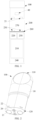
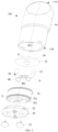
- FIG. 2 to FIG. 5 shows schematic structural diagrams of the atomizer 100 in FIG. 1 according to an embodiment.
- the atomizer includes a main housing 10.
- the main housing 10 is substantially in a shape of a flat cylinder. An interior thereof is hollow, which is a necessary functional component configured to store and atomize a liquid substrate.
- the main housing 10 has a proximal end 110 and a distal end 120 opposite to each other in a length direction. According to common use requirements, the proximal end 110 is configured as an aerosol inhalation end for a user, and a suction nozzle A is arranged on the proximal end 110 for inhalation by the user.
- the distal end 120 is an end to be coupled to the power supply assembly 200, and the distal end 120 of the main housing 10 is an open space in which a detachable end cap 20 is mounted.
- the open space structure is configured for necessary functional components to be mounted inside the main housing 10.
- the second electrical contact 21 runs into the atomizer 100 from a surface of the end cap 20, so that at least part of the second electrical contact is exposed from the atomizer 100, thereby coming into contact with the first electrical contact 230 to form electrical connection.
- a first air inlet 22 is further arranged on the end cap 20, which is configured for external air to enter the atomizer 100 during inhalation. Further referring to FIG. 3 , the second electrical contact 21 is flush with the surface of the end cap 20 after being assembled.
- the main housing 10 has arranged therein a liquid storage cavity 12 configured to store a liquid substrate and an atomization assembly configured to absorb the liquid substrate from the liquid storage cavity 12 and heat and atomize the liquid substrate.
- a vapor conveying tube 11 in an axial direction is arranged in the main housing 10, and the liquid storage cavity 12 configured to store the liquid substrate is formed in a space between an outer wall of the vapor conveying tube 11 and an inner wall of the main housing 10.
- a first end of the vapor conveying tube 11 opposite to the proximal end 110 is in communication with the suction nozzle A, to convey the generated aerosol to the suction nozzle A for inhalation.
- the vapor conveying tube 11 and the main housing 10 are integrally molded by using a moldable material, so that the prepared liquid storage cavity 12 forms an open space or an opening which opens toward the distal end 120.
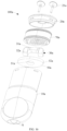
- the main housing 10 further includes a second liquid guide element 30, a heating element 40, and a support 70.
- the second liquid guide element 30 has a first portion 31 extending in a width direction of the main housing 10 and a second portion 32 extending in a longitudinal direction of the main housing 10 from the first portion 31.
- the second portion 32 is in fluid communication with the liquid storage cavity 12 through a first liquid guide element 50 in a shape of a sheet or a block.
- the second liquid guide element 30 is made of conventional flexible plant cotton, and the first liquid guide element 50 is prepared from oriented fibers and is in a hard form.
- the heating element 40 surrounds at least part of the first portion 31 to heat at least part of a liquid substrate in the first portion 31 to generate an aerosol.
- the support 70 is in a shape of a hollow cup or cylinder. An interior thereof is configured to hold the second liquid guide element 30 and define an atomization chamber surrounding the first portion 31. The aerosol generated by the heating element 40 through heating is released into the atomization chamber and then outputted to the vapor output tube 11. In addition, an upper end of the support 70 close to the liquid storage cavity 12 supports the first liquid guide element 50.
- the second liquid guide element 30 is a capillary element having an internal capillary channel therein, which absorbs and delivers the liquid substrate through capillary infiltration.
- the second liquid guide element 30 is a capillary element prepared from a flexible fiber material in a shape of a strip or a rod, for example, a capillary element of cotton fibers, non-woven fabric fibers, or a sponge.
- the second liquid guide element 30 is a capillary element having an internal capillary channel therein, for example, a porous ceramic body or a foam metal.
- the second portion 32 of the second liquid guide element 30 is configured to absorb the liquid substrate and then deliver the liquid substrate to the first portion 31 through capillary infiltration.
- the heating element 40 is constructed to surround at least part of the first portion 31 and heat at least part of the liquid substrate of the first portion 31 to generate an aerosol. As shown in FIG. 3 to FIG. 5 , the heating element 40 is constructed as a spiral heating wire, and may be made of resistive metal, such as aludirome or nichrome.
- an extension length of the first portion 31 of the second liquid guide element 30 in FIG. 5 is about 9 mm, and an extension length of the second portion 32 is about 7.5 mm.
- An inner diameter of the heating element 40 is in a range of about 2.3 mm to 2.6 mm.
- the first liquid guide element 50 is a layer of organic porous fibers in a shape of a sheet or a block extending in a cross-sectional direction of the main housing 10.
- an upper surface of the first liquid guide element 50 close to the liquid storage cavity 12 is opposite to the liquid storage cavity 12 and is configured to absorb the liquid substrate, and a lower surface facing away from the liquid storage cavity 12 delivers the liquid substrate to the second portion 32 of the second liquid guide element 30 with which the lower surface is in contact, as shown by an arrow R1 in FIG. 5 .
- a first plug-in hole 51 for the vapor conveying tube 11 to run through is arranged on the first liquid guide element 50.
- the first liquid guide element 50 is made of 138# hard synthetic organic polymer fiber cotton, which has a density in a range of 0.1 mg/mm 3 to 0.9 mg/mm 3 .
- An overall weight of the first liquid guide element 50 is in a range of about 0.04 g to 0.06 g.
- the first liquid guide element 50 is prepared from oriented fibers substantially in an oriented arrangement in the length direction.
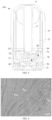
- FIG. 6 shows a microtopographic map of polypropylene fibers having an oriented arrangement according to an embodiment. By arranging the oriented fibers in the length direction of the first liquid guide element 50, the first liquid guide element 50 is endowed with a high anti-bending property and a rigidity.
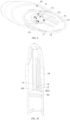
- the support 70 has a recess configured to accommodate the second liquid guide element 30 therein.
- the recess includes: a first holding recess 71, arranged on an inner bottom wall, extending in the width direction of the main housing 10, and configured to accommodate the first portion 31 of the second liquid guide element 30; and a second holding recess 72, extending in the longitudinal direction of the main housing 10 and configured to accommodate the second portion 32 of the second liquid guide element 30.
- the support 70 is preferably prepared from flexible materials such as silicone and thermoplastic elastomers, and a first convex rib 76 and a second convex rib 75 extending in a circumferential direction are arranged on an outer wall surface of the support 70.
- the first convex rib 76 and the second convex rib 75 are configured to seal a gap between the support 70 and the main housing 10.
- a second air inlet 77 toward the end cap 20 is further arranged on the support 70, which is configured for external air entering the atomizer through the first air inlet 22 to enter the atomization chamber in the support 70. Then the external air carries the aerosol in the atomization chamber and is outputted though the vapor conveying tube 11 running through the first plug-in hole 51.
- each of the convex edges 73 has a width in a range of about 0.5 mm to 1.5 mm, and the capillary trench 731 has a width less than 2 mm.
- a first notch 111 is arranged on an air inlet end of the vapor output tube 11 facing away from the suction nozzle A.
- two first notches 111 are arranged, which are arranged opposite to each other in a thickness direction of the main housing 10.
- a convex edge 74 at least partially extending into of the first notch 111 is arranged in the support 70.
- surfaces on two sides of the convex edge 74 are not in contact with surfaces on two sides of the first notch 111, and a specific spacing is held between the convex edge 74 and the surfaces on the two sides of the first notch 111, as shown in FIG. 12 .
- the spacing is controlled to be less than 2 mm to form a capillary channel enabling a capillary action between the convex edge and the first notch.
- the capillary force of the capillary channel adsorbs condensates in the vapor output tube 11 falling or flowing into the air inlet end, and guides the condensates into the atomization chamber of the support 70, thereby preventing the condensates from aggregating into a liquid column in the vapor output tube 11 and alleviating or eliminating a problem that the condensates are inhaled.
- a protrusion height of the convex edge 74 is greater than that of the convex edge 73, and a width thereof is the same as that of the convex edge 73.
- the protrusion height of the convex edge 74 varies. Specifically, an upper end portion in a longitudinal direction has a larger protrusion height than other portions.
- a cross-sectional shape of the vapor output tube 11 is an ellipse.
- the ellipse has a long axis B1 which is the width direction of the main housing 10 and a short axis B2 which is the thickness direction of the main housing 10, so that the condensate in the vapor output tube 11 tends to aggregate at an end portion of the major axis B1 with a relatively large curvature.
- a second notch 112 close to at least one side in the width direction of the main housing 10 is arranged on an end portion of the vapor output tube 11.
- the second notch 112 forms a hollow space on the end portion of the major axis B1 with the relatively large curvature, so that condensates are prevented from aggregating herein and thereby aggregating at a position close to the first notch 111, which facilitates guidance of the condensates into the atomization chamber with the cooperation of the convex edge 74.
- the first notch 111 has a larger width than the second notch 112.
- the width of the first notch 111 is about 2.4 mm
- the width of the second notch 112 is about 1 mm.
- the vapor output tube 11 has an oblique tube wall 113 close to the first notch 111.
- the aerosol condensate on an inner wall of the vapor output tube 11 is directed toward the first notch 111 by the oblique tube wall 113, then is adsorbed by the capillary channel formed between the convex edge 74 and the first notch 111 to the surface of the convex edge 74, and then flows downward into the atomization chamber in the support 70.
- the air pressure equilibration channel includes two channel portions in successive communication, that is, a first channel portion shown by an arrow R31 in FIG. 7 and FIG. 8 and a second channel portion shown by an arrow R32 in FIG.
- At least one convex edge 14 is arranged on each of inner walls on two sides of the main housing 10 close to the width direction.
- two convex edges 14 are arranged, and a specific spacing 141 is reserved between the two convex edges.
- a peripheral side wall of the hard first liquid guide element 50 in the FIG. 3 has a flat and straight portion 52. After assembly, the flat and straight portion 52 abuts against the convex edge 14 to define the spacing and prevent the spacing 141 from being filled or blocked.
- an air groove 79 is arranged on a surface of the support 70 close to the first liquid guide element 50.
- the air groove 79 is located on two end portions on two sides of the support 70 close to the width direction.
- One side of the air groove 79 is in communication with a space in the support 70, that is, the atomization chamber, and an other side is in communication with the spacing 141, so that air in the atomization chamber can pass through the air groove 79 in the arrow direction R31 in FIG. 7 and FIG. 8 , and then enter the liquid storage cavity 12 of the main housing 10 through the spacing 141 in the arrow direction R32 in the FIG. 10 , to alleviate or eliminate the negative pressure in the liquid storage cavity 12.
- a plurality of convex edges 13 are further arranged in the main housing 10, which are configured to abut against and press the first liquid guide element 50 from the upper surface of the first liquid guide element 50 after assembly.
- a second trench 711 extending in the thickness direction of the main housing 10 is arranged on a wall of the first holding recess 71.
- the second trench 711 is located on the heating element 40 or two sides of a part of the first portion 31 surrounded by the heating element 40 in the width direction of the main housing 10.
- a gap or a space is formed between a part close to an atomization area heated by the heating element 40 and the first portion 31, which is configured to buffer the liquid substrate to prevent the liquid substrate from flowing or being delivered directly and quickly to the part surrounded by the heating element 40, to alleviate splattering of the liquid substrate.
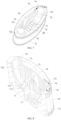
- an inner wall of the second holding recess 72 has a first trench 722 extending from an upper end to the second trench 711 in the longitudinal direction.
- the first trench 722 is configured to adsorb and buffer a liquid substrate seeping out through the second channel portion of the pressure equilibration channel during air compensation, and can regulate efficiency of a liquid substrate flowing on a surface of the second portion 32. It may be learned from FIG. 8 that an upper end of the first trench 722 is in communication with the air groove 79.
- the liquid substrate in the liquid storage cavity 12 seeps into the air groove 79 in a direction opposite to the direction shown by the arrow R32, the liquid substrate can be adsorbed into the first trench 722 and flow downward, as shown by the arrow R4 in FIG. 13 .
- the first trench 722 is a capillary trench with a width and/or a depth less than 2 mm, which adsorbs and delivers the liquid substrate through capillary infiltration.
- the first trench 722 has a width and/or a depth in a range of about 0.5 mm to 1.5 mm.
- the second holding recess 72 and the first holding recess 71 are spaced apart by the second trench 711, so that the second holding recess and the first holding recess are discrete.
- a surface of the second holding recess 72 is separated into at least two discrete portions by the first trench 722.
- a surface of the first holding recess 71 is separated into at least two discrete portions by the second trench 711.
- an extension length of the first trench 722 is greater than that of the second portion 32.
- the first trench at least partially extends into the first holding recess 71 along the air groove 79, and at least partially is adjacent to the surface of the first portion 31. Therefore, during use, the first trench 722 can directly supply the liquid substrate to the first portion 31.
- the air groove 79 is defined by protrusions 721 on the upper end of the support 70 surrounding the second holding recess 72. As shown in the figure, at least part of the air groove 79 is curved and surrounds the protrusions 721 of the second holding recess 72.
- FIG. 14 is a schematic diagram of the heating element 40 from perspective.
- the heating element includes a first electrical pin 41 and a second electrical pin 42 arranged opposite to each other in the length direction and a first spiral coil 410 and a second spiral coil 420 extending between the first electrical pin 41 and the second electrical pin 42.
- the first spiral coil 410 and the second spiral coil 420 are simultaneously powered by the first electrical pin 41 and the second electrical pin 42, and are connected in parallel.
- the first spiral coil 410 and the second spiral coil 420 are arranged snugly side by side.
- the first spiral coil 410 and the second spiral coil 420 each have about 3 to 10 turns or windings and an extension length in a range of about 4 mm to 7 mm.
- the first spiral coil and the second spiral coil each have 5 turns or windings and a design length of 6.5 mm.
- the first spiral coil 410 and the second spiral coil 420 are not arranged in an overlapping manner in a radial direction, and are arranged in parallel or staggered with respect to each other in an axial direction. At least the first spiral coil and the second spiral coil are at different positions relative to the first portion 31 in an extension direction of the first portion 31 after assembly, and therefore have higher contact area heating efficiency with the first portion 31.
- a wire material used for the first electrical pin 41 and the second electrical pin 42 has a larger diameter than a wire material used for the first spiral coil 410 and the second spiral coil 420.
- the first electrical pin 41 and the second electrical pin 42 each are prepared by using a relatively thick wire
- the first spiral coil 410 and the second spiral coil 420 each are prepared by using a relatively thin wire to facilitate connection of two ends of the first spiral coil and the second spiral coil to the first electrical pin 41 and the second electrical pin 42.
- the first electrical pin 41 and the second electrical pin 42 each are prepared by using a wire with a diameter of about 0.25 mm
- the first spiral coil 410 and the second spiral coil 420 each are prepared by using a wire with a diameter of 0.15 mm.
- the first spiral coil 410 and the second spiral coil 420 each are prepared by using suitable resistive metal or alloy, such as aludirome or nichrome, which have a relatively large temperature coefficient of resistance.
- the first electrical pin 41 and the second electrical pin 42 each serve as an electrical pin, and are prepared by using metal or alloy with relatively high conductivity and low resistivity, such as gold, silver, or copper, or each are an elongated pin prepared by forming a metal coating on an outer surface of a filamentous substrate.
- the first electrical pin 41 includes an annular support portion 411 and an electrical connection portion 412.
- the annular support portion 411 is connected to the first spiral coil 410 and the second spiral coil 420, and sizes of spirals, such as outer diameters or inner diameters of the annular support portion, the first spiral coil, and the second spiral coil are substantially the same.
- the annular support portion 411 can surround the first portion 31 of the second liquid guide element 30, so that the annular support portion 411 of the first electrical pin 41 supports the first portion 31 of the second liquid guide element 30 after assembly.
- the electrical connection portion 412 runs to outside of the support 70 to abut against or to be welded with the second electrical contact 21.
- the first spiral coil 410 and the second spiral coil 420 of the heating element 40 are not in contact with the inner wall of the support 70 and/or the wall of the first holding recess 71 after assembly. Instead, the first spiral coil and the second spiral coil are held on the inner wall of the support 70 and/or the wall of the first holding recess 71 through the annular support portion 411 of the first electrical pin 41, thereby supporting the heating element 40.
- the first electrical pin 41 and the second electrical pin 42 have a lower temperature than the first spiral coil 410 and the second spiral coil 420, thereby avoiding thermal damage to the support 70.
- the electrical connection portion 412 of the first electrical pin 41 is in a shape of a bent hook.
- the support 70 has a lead hole 781 running from the inner wall to a surface toward the end cap 20 and a contact hole 782 arranged toward the end cap 20 and configured to accommodate at least part of the second electrical contact 21.
- the electrical connection portion 412 runs through the lead hole 781 and then extends or bends into the contact hole 782 to form electrical connection to the second electrical contact 21.
- the second electrical pin 42 has the same construction, connection, and assembly as the first electrical pin 41.
- the heating element 40 has an inner diameter in a range of about 2 mm to 4 mm, and preferably, in a range of 2.3 mm to 2.6 mm.
- the heating element 40 has a resistance in a range of about 0.5 ohms to 2 ohms.
- a spiral coil portion formed by the first spiral coil 410 and the second spiral coil 420 of the heating element 40 side by side has a length in a range of about 4.2 mm to 5 mm.
- 5 turns or windings are arranged, and each turn or winding has a length of about 1 mm.
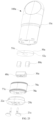
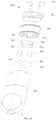
- FIG. 15 to FIG. 17 are respectively a schematic exploded view and a schematic sectional view of an atomizer 100a according to another embodiment.
- the atomizer 100a includes a main housing 10a, a second liquid guide element 30a, a heating element 40a, a support 70a, an end cap 20a, and a second electrical contact 21a.
- the main housing 10a has arranged therein a vapor output tube 11a extending in a longitudinal direction and a liquid storage cavity 12a defined by the vapor output tube 11a and an inner wall of the main housing 10a.
- the second liquid guide element 30a has a first portion 31a extending in a width direction of the main housing 10a and a second portion 32a extending in a longitudinal direction of the main housing 10a from the first portion 31a.
- the second portion 32a is in fluid communication with the liquid storage cavity 12a through a first liquid guide element 50a in a shape of a sheet or a block.
- the first liquid guide element 50a is prepared from oriented fibers and is in a hard form.
- the second liquid guide element 30a is a rigid porous body, for example, a porous ceramic body.
- the heating element 40a is formed on the first portion 31 to heat at least part of a liquid substrate in the first portion 31a to generate an aerosol.
- the support 70a is in a shape of a hollow cup or cylinder. An interior thereof is configured to hold the second liquid guide element 30a and define an atomization chamber surrounding the first portion 31a. The aerosol generated by the heating element 40a through heating is released into the atomization chamber and then outputted to the vapor output tube 11a. In addition, an upper end of the support 70a close to the liquid storage cavity 12a supports the first liquid guide element 50a.
- the end cap 20a is configured to seal an open end of the main housing 10a, and has a second electrical contact 21a and a first air inlet 22a arranged thereon.
- the second electrical contact 21a runs through a contact hole 78a on the support 70a through the end cap 20a to abut against the heating element 40a, and is configured to supply power to the heating element 40a.
- the second liquid guide element 30a prepared from the porous ceramic body is substantially in a shape of U.
- the second liquid guide element 30a has a length size d1 of about 13 mm, a width size d2 of about 3 mm, and a height size d4 of about 5 mm.
- a length size d11 of the first portion 31a of the second liquid guide element 30a is about 7 mm. In other words, a size of a U-shaped opening is 7 mm.
- a height size d41 of the first portion 31a is about 2 mm.
- a length size d3 of the second portion 32a of the second liquid guide element 30a is about is about 3 mm.
- An outer surface 310 of the first portion 31a of the second liquid guide element 30a facing away from the U-shaped opening is constructed substantially in a shape of a plane, and the outer surface 310 is configured as an atomization surface 310a configured to atomize the liquid substrate.
- the heating element 40a is constructed to be coupled to the atomization surface 310a.
- a liquid substrate absorbed by the second portion 32a is delivered to the atomization surface 310a, and is heated and atomized by the heating element 40 to generate an aerosol.
- the aerosol is released into the atomization chamber in the support 70a through the atomization surface 310a, and then is outputted with an inhalable airflow.
- the heating element 40a has a conductive portion 41a located on each of two ends and a resistance heating trajectory portion 42a extending zigzag in a length direction of the first portion 31a.
- the second electrical contact 21a abuts against the conductive portion 41a to supply power to the resistance heating trajectory portion 42a.
- the resistance heating trajectory portion 42a is a trajectory formed through printing, etching, printing, or the like. In some other implementations, the resistance heating trajectory portion 42a is a patterned trajectory.
- the second liquid guide element 30a is a rigid porous body. After assembly, a front end of the second portion 32a of the second liquid guide element 30a abuts against a lower surface of the first liquid guide element 50a to support the first liquid guide element 50a and to receive the liquid substrate from the first liquid guide element 50a.
- FIG. 20 to FIG. 21 are schematic structural diagrams of an atomizer 100b according to another embodiment.
- a hole 53b is arranged to run through a first liquid guide element 50b in a thickness direction.
- a second portion 321b of a second liquid guide element 30b runs through the hole 53b from a lower surface of the first liquid guide element 50b, and is exposed from a liquid storage cavity 12b to directly absorb a liquid substrate in the liquid storage cavity 12b.
- the second portion 321b of the second liquid guide element 30b has an insertion segment 321b with a relatively small outer diameter, and is in communication with the liquid storage cavity 12b after the insertion segment 321b runs through the hole 53b of the first liquid guide element 50b.
- a sectional width or length of the insertion segment 321b is 2 mm.
- a step is formed at a joint of the insertion segment 321b the second portion 321b. The step abuts against the lower surface of the first liquid guide element 50b, to support and hold the first liquid guide element 50b.
- FIG. 22 is a schematic structural diagram of a second liquid guide element 30f that may be used for the atomizer 100b according to another embodiment.
- an upper surface of a first portion 31f of the second liquid guide element 30f is constructed as an atomization surface 310f.
- a heating element 40f is formed on the atomization surface 310f defined by the upper surface.
- the heating element 40f and/or the atomization surface 310f is toward the first liquid guide element 50b.
- the heating element 40f is formed on the atomization surface 310f through printing, deposition, etching, mounting, or the like.
- a conductive portion 41f of the heating element 40f is connected to the second electrical contact 21b through an elastic piece, lead welding, or the like to supply power to the heating element 40f.
- the second liquid guide element 30f may further have another shape or construction, for example, an L shape.
- FIG. 23 to FIG. 25 are schematic structural diagrams of an atomizer 100c according to another embodiment.
- the atomizer 100c includes a main housing 10c, an end cap 20c, and a first liquid guide element 50c.
- the main housing 10c has a suction nozzle A configured for inhalation on a proximal end thereof.
- the main housing 10c has a vapor output tube 11c and a liquid storage cavity 12c defined by the vapor output tube 11c therein.
- the liquid storage cavity 12c has an opening toward a distal end.
- the end cap 20c is coupled to an open space at the distal end of the main housing 10c, to define an outer housing of the atomizer 100c with the main housing 10c.
- the first liquid guide element 50c is in a shape of a sheet or a block perpendicular to the main housing 10c, which crosses and covers the opening of the liquid storage cavity 12c after assembly, to seal the liquid storage cavity 12c, so that a liquid substrate in the liquid storage cavity 12c may substantially leave through only the first liquid guide element 50c.
- the first liquid guide element 50c has a profile substantially in a shape of an ellipse.
- the first liquid guide element 50c is made of the hard organic cotton for making the first liquid guide element 50 in the above embodiments.
- the atomizer 100c further includes a second liquid guide element 30c, a heating element 40c, and a third liquid guide element 80c.
- the second liquid guide element 30c overall has a first side wall 31c and a second side wall 32c opposite to each other in a thickness direction and a notch located between the first side wall 31c and the second side wall 32c.
- the second liquid guide element 30c further has an atomization surface 310c facing away from the first side wall 31c and/or the second side wall 32c and/or the notch in a longitudinal direction.
- the second liquid guide element 30c is rigid, and is made of the porous body in the above embodiments, for example, a porous ceramic body.
- the heating element 40c is coupled to the atomization surface 310c to heat at least part of a liquid substrate in the second liquid guide element 30c to generate an aerosol and release the aerosol through the atomization surface 310c.
- the third liquid guide element 80c is configured to deliver the liquid substrate between the first liquid guide element 50c and the second liquid guide element 30c, so that a liquid substrate absorbed by the first liquid guide element 50c is delivered to the second liquid guide element 30c.
- the third liquid guide element 80c is flexible, for example, is a sponge. As shown in FIG. 26 , after assembly, at least part of the third liquid guide element 80c is accommodated and held within a notch 33c of the second liquid guide element 30c, and is in contact with both the first liquid guide element 50c and the second liquid guide element 30c, to form fluid communication with the first liquid guide element and the second liquid guide element, so as to deliver the liquid substrate between the first liquid guide element and the second liquid guide element.
- the third liquid guide element 80c is substantially in a shape of a block, a column, or a strip, an upper end thereof abuts against the first liquid guide element 50c, and a lower end abuts against the second liquid guide element 30c, to implement liquid delivery between the first liquid guide element and the second liquid guide element.
- a second liquid guide element 30e shown in FIG. 30 An upper surface of the second liquid guide element 30e has a groove 33e, and the groove 33e accommodates and holds at least part of the third liquid guide element 80c.
- the third liquid guide element 80c is in contact with or abuts against a surface of the second liquid guide element 30e defining the groove 33e to form fluid communication, thereby delivering the liquid substrate.
- an accommodating or supporting structure such as a clamping port, a holding cavity, or a recess is formed on the second liquid guide element 30c/30e, to accommodate at least part of the third liquid guide element 80c and support or hold the third liquid guide element 80c.
- the atomizer further includes a support 70c configured to accommodate and hold the second liquid guide element 30c and the third liquid guide element 80c and define an atomization chamber for aerosol release with at least part of the atomization surface 310c;
- a support 70c configured to accommodate and hold the second liquid guide element 30c and the third liquid guide element 80c and define an atomization chamber for aerosol release with at least part of the atomization surface 310c;
- an electrode hole 78c for a second electrical contact 21c to run through so as to abut against the heating element 40c is further arranged, and a second air inlet 77c for external air entering the atomizer through a first air inlet 22c to enter the atomization chamber is further arranged.
- the support 70c further abuts against a lower surface of the first liquid guide element 50c, to support and hold at least part of the first liquid guide element 50c.
- the vapor output tube 11c runs through a first plug-in hole 51d on the first liquid guide element 50c to be
- the third liquid guide element 80c has an exposed portion 81c exposed from the notch of the second liquid guide element 30c in a length direction of the second liquid guide element 30c. After assembly, the exposed portion 81c is supported by the support 70c.
- a gap exists between the first side wall 31c of the second liquid guide element 30c and the inner wall of the support 70c and between the second side wall 32c of the second liquid guide element 30c and the inner wall of the support 70c, to form a channel 71c.
- the air carries the aerosol and crosses the second liquid guide element 30c through the channel 71c, and then is outputted to the vapor output tube 11c at a central portion close to the vapor output tube 11c.
- a retaining protrusion 72c configured to fix and hold the second liquid guide element 30c is arranged on the inner wall of the support 70c. After assembly, an upper end surface of the first side wall 31c and/or the second side wall 32c of the second liquid guide element 30c abuts against the retaining protrusion 72c, so that the second liquid guide element 30c is stably held in the support 70c.
- the support 70c has grooves 79c on two sides in a width direction, which are in airflow communication with a space in the support 70c, so that external air entering the atomization chamber can enter the grooves 79c according to the arrow R3, and then enter the liquid storage cavity 12c through a gap between a flat and straight portion 52c on a peripheral side wall of the first liquid guide element 50c and the main housing 10c.
- the structure of the second liquid guide element 30c further includes a substrate portion 34c and a connection portion 35c.
- the substrate portion 34c is located on a lower end side of the second liquid guide element 30c in the longitudinal direction, and extends between the first side wall 31c and the second side wall 32c.
- an extension length of the substrate portion 34c in the length direction of the second liquid guide element 30c is the same as an extension length of the first side wall 31c and/or the second side wall 32c.
- a lower surface of the substrate portion 34c is used as the atomization surface 310c, and a lower end of the third liquid guide element 80c abuts against an upper surface of the substrate portion 34c.
- connection portion 35c is located on an upper end side of the second liquid guide element 30c in the longitudinal direction, and is arranged close to a central portion of the second liquid guide element 30c. Similarly, the connection portion 35c extends between the first side wall 31c and the second side wall 32c. In addition, an extension length of the connection portion 35c in the length direction of the second liquid guide element 30c is less than the extension length of the first side wall 31c and/or the second side wall 32c and/or the substrate portion 34c. In this way, a region not covered by the connection portion 35c forms the notch 33c.
- a space 36c extending in the length direction is defined between the connection portion 35c and the substrate portion 34c. After assembly, the space 36c is surrounded or shielded by the third liquid guide element 80c. In this way, the space 36c may be configured to receive or buffer a liquid substrate seeping out through a surface of the third liquid guide element 80c, to adjust an amount or efficiency of supply of the liquid substrate to the atomization surface 310c.
- connection portion 35c of the second liquid guide element 30c is opposite to the first plug-in hole 51c of the first liquid guide element 50c in the longitudinal direction of the main housing 10c. Therefore, in an implementation, the connection portion 35c may be configured to receive an aerosol condensate falling from the vapor output tube 11c.
- FIG. 31 is a schematic sectional view of the support 70c from a perspective.
- the support 70c has a first step 73c and a second step 74c provided or formed therein.
- the first step 73c is configured to support the second liquid guide element 30c. Specifically, after assembly, at least part on an end side in a length direction of the atomization surface 310c of the second liquid guide element 30c abuts against the first step 73c.
- the electrode hole 78c extends or runs into the first step 73c, so that the second electrical contact 21c can abut against a conductive portion of the heating element 40c on the atomization surface 310c after running through the electrode hole 78c, thereby supplying power to the heating element 40c.
- the second step 74c is configured to support the exposed portion 81c of the third liquid guide element 80c protruding from the notch 33c of the second liquid guide element 30c.
- the first step 73c and the second step 74c have different heights in the longitudinal direction.
- the first step 73c and the second step 74c are arranged on two sides of an inner surface of the support 70c close to the width direction.
- the first step 73c and an inner bottom wall 76c of the support 70c have different heights in the longitudinal direction.
- a spacing 340c is formed between the atomization surface 310c of the second liquid guide element 30c and the inner bottom wall 76c of the support 70c, which forms the atomization chamber configured to accommodate the aerosol.
- a capillary trench 75c is arranged on a side wall of the spacing 340c and on the inner bottom wall 76c.
- the capillary trench 75c has a width in a range of about 0.5 mm to 2 mm to adsorb an aerosol condensate in the atomization chamber.
- FIG. 32 to FIG. 35 are schematic structural diagrams of an atomizer 100d according to another embodiment.
- the atomizer 100d includes a main housing 10d, an end cap 20d, a first liquid guide element 50d, a second liquid guide element 30d, a heating element 40d, and a third liquid guide element 80d.
- the main housing 10d has a suction nozzle A configured for inhalation on a proximal end thereof.
- the main housing 10d has a vapor output tube 11d and a liquid storage cavity 12d defined by the vapor output tube 11d therein.
- the liquid storage cavity 12d has an opening toward a distal end.
- the end cap 20d is coupled to an open space at the distal end of the main housing 10d, to define an outer housing of the atomizer 100d with the main housing 10d.
- the first liquid guide element 50d is in a shape of a sheet or a block perpendicular to the main housing 10d.
- the first liquid guide element 50d has a profile substantially in a shape of an ellipse.
- the first liquid guide element 50d is made of the hard organic cotton for making the first liquid guide element 50 in the above embodiments.
- the second liquid guide element 30d is overall in a shape of a sheet or a plate perpendicular to a longitudinal direction of the main housing 10d.
- An upper surface thereof in a thickness direction is in fluid communication with the first liquid guide element 50d to receive a liquid substrate.
- a lower surface thereof in the thickness direction is constructed as an atomization surface 310d.
- the second liquid guide element 30d is rigid, and is made of the porous body in the above embodiments, for example, a porous ceramic body.
- the heating element 40d is formed on the atomization surface 310d, and is configured to heat at least part of a liquid substrate in the second liquid guide element 30d to generate an aerosol.
- the third liquid guide element 80d is positioned between the first liquid guide element 50d and the second liquid guide element 30d in the longitudinal direction of the main housing 10d, to deliver the liquid substrate between the first liquid guide element and the second liquid guide element.
- the third liquid guide element 80d is a substantially in a shape of U, and includes a third portion 81d in a direction perpendicular to the longitudinal direction of the main housing 10d and a fourth portion 82d extending from the third portion 81d toward the first liquid guide element 50d.
- the third portion 81d is in contact with and abuts against an upper surface of the second liquid guide element 30d to form fluid communication with the second liquid guide element 30d
- the fourth portion 82d extends to and abuts against a lower surface of the first liquid guide element 50d to form fluid communication with the first liquid guide element 50d.
- an extension length of the third portion 81d is greater than a length of the second liquid guide element 30d. Therefore, after assembly, at least part of the third portion 81d protrudes relative to the second liquid guide element 30d, and protruding portion abuts against a support 70d and is at least partially supported by the support 70d. Similarly, the third portion 81d further abuts against the second liquid guide element 30d, so that the third portion 81d is at least partially supported by the second liquid guide element 30d.
- two side walls of the support 70d in a thickness direction each have a window 76d extending in the longitudinal direction.
- an output channel is defined between the window 76d and an inner wall of the main housing 10d.
- an extension length of the window 76d in the longitudinal direction covers at least an atomization chamber 340d defined by the atomization surface 310d of the second liquid guide element 30d, so that air entering the atomization chamber 340d through a second air inlet 77d can enter the output channel defined between the window 76d and the inner wall of the main housing 10d, and then crosses a U-shaped opening of the third liquid guide element 80d according to an arrow R2 in the figure to be outputted to the vapor output tube 11d.
- a groove 79d is arranged on a surface of the support 70c adjacent to the first liquid guide element 50d, this recess being in airflow communication with the output channel indicated by the arrow R2. Therefore, after assembly, when a negative pressure in the liquid storage cavity 12d exceeds a specific threshold range, the air can successively pass through a first channel portion defined by the groove 79d indicated by an arrow R31 in FIG. 36 and a second channel portion defined between a flat and straight portion 52d of a peripheral side wall of the first liquid guide element 50d and the inner wall of the main housing 10d, to enter the liquid storage cavity 12d to alleviate the negative pressure.
- the support 70d has a first boss 73d, a second boss 74d, an electrode hole 78d, and a capillary trench 75d.
- the first boss 73d is configured to abut against the atomization surface 310d of the second liquid guide element 30d, to support the second liquid guide element 30d.
- the second boss 74d is configured to abut against a part of the third liquid guide element 80d protruding from or exposed from the second liquid guide element 30d, to support the third liquid guide element 80d.
- the electrode hole 78d is configured for a second electrical contact 21d to run through to abut against the atomization surface 310d, so as to supply power to the heating element.
- the capillary trench 75d is formed on an inner bottom wall of the support 70d and on a surface of a space between the first boss 73d and the inner bottom wall, to adsorb an aerosol condensate in the atomization chamber.
Landscapes
- Special Spraying Apparatus (AREA)
Abstract
Description
- This application claims priority to a previous application with
Chinese Patent Application No. 202111097119.1, filed with the China National Intellectual Property Administration on September 18, 2021 - Embodiments of this application relate to the field of electronic atomization technologies, and in particular, to an atomizer and an electronic atomization device.
- Smoking products (such as cigarettes and cigars) bum tobacco to produce tobacco smoke during use. Attempts are made to manufacture products that release compounds without burning of tobacco to replace these tobacco-burning products.
- A heating device is an example of the products, which releases compounds by heating rather than burning of materials. For example, the materials may be tobacco or non-tobacco products that may or may not include nicotine. As another example, products providing aerosols, for example, electronic atomization devices, exist. The devices usually include an atomizable liquid, which is heated to be atomized, so as to generate an inhalable aerosol. In the above electronic atomization devices, a liquid guide element delivers excessive liquid substrates or delivers the liquid substrates excessively rapidly to a joint of a heating element, forming splattering of the liquid substrates during heating.
- An embodiment of this application provides an atomizer, configured to atomize a liquid substrate to generate an aerosol, and including an outer housing. The outer housing has arranged therein:
- a liquid storage cavity, configured to store a liquid substrate;
- a heating element, configured to heat at least part of the liquid substrate to generate an aerosol;
- a capillary element, including a first portion coupled to the heating element and a second portion extending from the first portion toward the liquid storage cavity, where the second portion is constructed to absorb the liquid substrate from the liquid storage cavity and deliver the liquid substrate to the first portion; and
- a support, configured to hold the capillary element, where the support includes a recess configured to accommodate at least part of the capillary element, the support is provided with a first trench formed on a surface of the recess, and the first trench extends in parallel with the second portion of the capillary element and is adj acent to an outer surface of the second portion.
- In a preferred implementation, the recess includes a first holding recess configured to accommodate at least part of the first portion and a second holding recess configured to accommodate at least part of the second portion.
- In a preferred implementation, the first trench extends from a surface of the second holding recess to the first holding recess.
- In a preferred implementation, the second holding recess and the first holding recess are discrete.
- In a preferred implementation, the surface of the recess includes two discrete portions.
- In a preferred implementation, the first trench is a capillary trench.
- In a preferred implementation, the first trench is constructed to be in fluid communication with the liquid storage cavity.
- In a preferred implementation, at least part of the first trench is constructed to be bent.
- In a preferred implementation, a second trench is arranged on the surface of the first holding recess.
- In a preferred implementation, the second trench is arranged perpendicular to an extension direction of the first portion.
- In a preferred implementation, the first trench extends to be in communication with the second trench.
- In a preferred implementation, an extension length of the first trench in a longitudinal direction of the outer housing is greater than an extension length of the second portion.
- In a preferred implementation, the capillary element is rigid.
- In a preferred implementation, the capillary element includes a porous ceramic body.
- In a preferred implementation, the first portion has an atomization surface facing away from the second portion, and the heating element is coupled to the atomization surface.
- In a preferred implementation, the heating element includes a resistance heating trajectory coupled to the atomization surface.
- In a preferred implementation, the outer housing further has arranged therein:
a first liquid guide element, constructed to extend in a direction perpendicular to a longitudinal direction of the outer housing and arranged between the liquid storage cavity and the capillary element in the longitudinal direction of the outer housing. The first liquid guide element has a first surface close to the liquid storage cavity in the longitudinal direction of the outer housing and a second surface facing away from the first surface. The first surface is configured to be in fluid communication with the liquid storage cavity to absorb the liquid substrate in the liquid storage cavity. - The second portion is constructed to be in contact with the second surface to absorb the liquid substrate.
- In a preferred implementation, the atomizer further includes:
an air channel, configured to provide a fluid path for air to cross the first liquid guide element in the longitudinal direction of the outer housing to enter the liquid storage cavity. - The first trench is constructed to be in fluid communication with the liquid storage cavity through the air channel.
- In a preferred implementation, the air channel includes a first channel portion formed between the first liquid guide element and the outer housing and a second channel portion formed between the first support and the first liquid guide element. The first trench is in communication with the second channel portion.
- In a preferred implementation, the second channel portion includes a groove formed on the second surface of the first liquid guide element adjacent to the support.
- In a preferred implementation, the outer housing further has arranged therein:
a first liquid guide element, constructed to extend in a direction perpendicular to a longitudinal direction of the outer housing and arranged between the liquid storage cavity and the capillary element in the longitudinal direction of the outer housing. - The second portion is constructed to at least partially run through the first liquid guide element in the longitudinal direction of the outer housing.
- Another embodiment of this application further provides an electronic atomization device, including an atomizer configured to atomize a liquid substrate to generate an aerosol and a power supply assembly configured to supply power to the atomizer. The atomizer includes the atomizer described above.
- An embodiment of this application provides an atomizer, including an outer housing. The outer housing has arranged therein:
- a liquid storage cavity, configured to store a liquid substrate and having an opening;
- a first liquid guide element, configured to cover the opening to seal the liquid storage cavity, so that the liquid substrate in the liquid storage cavity substantially leaves through the first liquid guide element, where the first liquid guide element has a first surface close to the liquid storage cavity in a longitudinal direction of the outer housing and a second surface facing away from the first surface; and the first surface is configured to be in fluid communication with the liquid storage cavity to absorb the liquid substrate in the liquid storage cavity;
- a second liquid guide element, in fluid communication with the second surface of the first liquid guide element to absorb a liquid substrate in the first liquid guide element, where the second liquid guide element has an atomization surface; and
- a heating element, coupled to the atomization surface and configured to heat at least part of a liquid substrate in the second liquid guide element to generate an aerosol.
- In a preferred implementation, the first liquid guide element is made of an elastic organic porous material.
- In a preferred implementation, the first liquid guide element has an elastic modulus or a rigidity less than that of a material of the liquid storage cavity and greater than that of a material of the second liquid guide element.
- In a preferred implementation, the first liquid guide element directly contacts and covers the opening of the liquid storage cavity.
- In a preferred implementation, the first liquid guide element is constructed in a shape of a sheet or a block perpendicular to the longitudinal direction of the outer housing.
- In a preferred implementation, the first liquid guide element has a length direction perpendicular to the longitudinal direction of the outer housing and a width direction perpendicular to the longitudinal direction of the outer housing and the length direction. A length dimension of the first liquid guide element is greater than a width dimension.
- In a preferred implementation, the first liquid guide element is anisotropic. Preferably, a flexural strength in the length direction is greater than a flexural strength in the width direction. More preferably, a liquid guide rate in the length direction is greater than a liquid guide rate in the width direction. Further preferably, the first liquid guide element includes fibers arranged and oriented substantially in the length direction.
- In a preferred implementation, the first liquid guide element has a Shore hardness in a range of 20 A to 70 A. More preferably, the first liquid guide element has a Shore hardness in a range of 50 A to 70 A.
- In a preferred implementation, the second liquid guide element is flexible and has a Shore hardness less than that of the first liquid guide element.
- In a preferred implementation, a flexible sealing material is arranged between the first liquid guide element and the liquid storage cavity.
- In a preferred implementation, the first liquid guide element is constructed substantially in a shape of an elliptical column.
- In a preferred implementation, the first surface and/or the second surface of the first liquid guide element have patterns extending substantially in the length direction.
- In a preferred implementation, a vapor output tube extending in the longitudinal direction is further arranged in the outer housing, which is configured to output the aerosol. A first plug-in hole for the vapor output tube to run through is arranged on the first liquid guide element.
- In a preferred implementation, the first plug-in hole has an elliptical cross section. A length direction of the cross section of the first plug-in hole is parallel to the length direction of the first liquid guide element.
- In a preferred implementation, the second liquid guide element is rigid.
- In a preferred implementation, the second liquid guide element includes a porous ceramic body.
- In a preferred implementation, the atomization surface is arranged to be located on a side of the second liquid guide element facing away from the first liquid guide element.
- In a preferred implementation, the atomization surface is arranged to be located on a side of the second liquid guide element toward the first liquid guide element.
- In a preferred implementation, the second liquid guide element is arranged to be in contact with the second surface to be in fluid communication with the second surface.
- In a preferred implementation, the second liquid guide element includes a first portion extending in a direction perpendicular to the longitudinal direction of the outer housing and a second portion extending from the first portion toward the second surface.
- The second portion is constructed to be in contact with the second surface.
- The atomization surface is located on the first portion.
- In a preferred implementation, an extension length of the first portion is greater than an extension length of the second portion.
- In a preferred implementation, the second liquid guide element is further constructed to abut against the second surface to support at least part of the first liquid guide element.
- In a preferred implementation, a first convex edge extending in the longitudinal direction of the outer housing is further arranged in the outer housing.
- The first convex edge is constructed to abut against the first surface to hold at least part of the first liquid guide element.
- In a preferred implementation, the liquid storage cavity has an opening. The first liquid guide element is configured to cover the opening to seal the liquid storage cavity, so that the liquid substrate in the liquid storage cavity substantially leaves through the first liquid guide element.
- In a preferred implementation, the atomizer further includes:
a third liquid guide element, positioned between the second surface of the first liquid guide element and the second liquid guide element in the longitudinal direction of the outer housing. The second liquid guide element is in fluid communication with the second surface through the third liquid guide element. - In a preferred implementation, the third liquid guide element is flexible.
- In a preferred implementation, the second liquid guide element is constructed to accommodate or support at least part of the third liquid guide element.
- In a preferred implementation, the second liquid guide element has a notch, a groove, or a recess toward the first liquid guide element.
- At least part of the third liquid guide element is accommodated or held in the notch, the groove, or the recess.
- In a preferred implementation, the third liquid guide element is constructed in a shape of a strip, a block, or a column extending in the longitudinal direction of the outer housing.
- In a preferred implementation, the third liquid guide element includes a third portion perpendicular to the longitudinal direction of the outer housing and a fourth portion extending in the longitudinal direction of the outer housing from the third portion.
- The fourth portion is in contact with the second surface.
- The third portion is in contact with the second liquid guide element.
- In a preferred implementation, the second liquid guide element is constructed as a sheet or a plate perpendicular to the longitudinal direction of the main housing.
- In a preferred implementation, the atomizer further includes:
a support, constructed to accommodate and hold at least part of the second liquid guide element and of the third liquid guide element. - In a preferred implementation, the support includes:
- a first step, configured to support at least part of the second liquid guide element; and
- a second step, configured to support at least part of the third liquid guide element.
- The first step and the second step have different heights in a longitudinal direction of the outer housing.
- In a preferred implementation, the atomizer further includes:
a support, constructed to abut against the second surface to hold at least part of the first liquid guide element. - In a preferred implementation, the atomizer further includes:
an air channel, configured to provide a fluid path for air to cross the first liquid guide element in a longitudinal direction of the outer housing to enter the liquid storage cavity. - In a preferred implementation, the outer housing has arranged therein: an inner wall, configured to define the liquid storage cavity configured to store the liquid substrate. The first liquid guide element has a peripheral side wall extending between the first surface and the second surface.
- At least part of an air channel is formed between the peripheral side wall and the inner wall.
- In a preferred implementation, a second convex edge extending in a longitudinal direction of the outer housing is arranged on the inner wall. The peripheral side wall has a flat and straight portion adjacent to the inner wall, and the flat and straight portion abuts against the second convex edge, so that a gap is retained between the peripheral side wall and the inner wall to define at least part of the air channel.
- In a preferred implementation, the heating element includes a resistance heating trajectory formed on the atomization surface.
- Another embodiment of this application further provides an atomizer, which is configured to atomize a liquid substrate to generate an aerosol, and includes an outer housing. The outer housing has arranged therein:
- a liquid storage cavity, configured to store a liquid substrate;
- a second liquid guide element, including a first portion extending in direction perpendicular to a longitudinal direction of the outer housing and a second portion extending from the first portion toward the liquid storage cavity, where
- the second portion is constructed to be in fluid communication with the liquid storage cavity to absorb the liquid substrate; and
- the first portion has an atomization surface facing away from the second portion; and
- a heating element, coupled to the atomization surface and configured to heat at least part of a liquid substrate in a second liquid guide element to generate an aerosol.
- In a preferred implementation, the second liquid guide element is rigid.
- In a preferred implementation, the second liquid guide element includes a porous ceramic body.
- In a preferred implementation, an extension length of the first portion is greater than an extension length of the second portion.
- In a preferred implementation, the atomizer further includes:
a first liquid guide element, constructed to extend in a direction perpendicular to a longitudinal direction of the outer housing and arranged between the liquid storage cavity and the second liquid guide element in the longitudinal direction of the outer housing. The first liquid guide element has a first surface close to the liquid storage cavity in the longitudinal direction of the outer housing and a second surface facing away from the first surface. The first surface is configured to be in fluid communication with the liquid storage cavity to absorb the liquid substrate in the liquid storage cavity. - The second portion is constructed to be in contact with the second surface to absorb the liquid substrate.
- In a preferred implementation, the second liquid guide element is further constructed to abut against the second surface to support at least part of the first liquid guide element.
- In a preferred implementation, a first convex edge extending in a longitudinal direction of the outer housing is further arranged in the outer housing.
the first convex edge is constructed to abut against the first surface to hold at least part of the first liquid guide element. - In a preferred implementation, the atomizer further includes:
a first liquid guide element, constructed to extend in the direction perpendicular to the longitudinal direction of the outer housing and arranged between the liquid storage cavity and the second liquid guide element in the longitudinal direction of the outer housing. - The second portion is constructed to at least partially run through the first liquid guide element in the longitudinal direction of the outer housing.
- In a preferred implementation, the second portion has an insertion segment with a cross-sectional area less than those of other portions, and the insertion segment runs through the first liquid guide element to be in fluid communication with the liquid storage cavity.
- In a preferred implementation, the second has a step defined by the insertion segment, and the step abuts against the second surface to support at least part of the first liquid guide element.
- In a preferred implementation, the atomizer further includes:
an air channel, configured to provide a fluid path for air to cross the first liquid guide element in a longitudinal direction of the outer housing to enter the liquid storage cavity. - In a preferred implementation, the outer housing has arranged therein: an inner wall, configured to define the liquid storage cavity configured to store the liquid substrate.
- The air channel includes a first channel portion. The first channel portion is formed between the first liquid guide element and the inner wall.
- In a preferred implementation, the first liquid guide element has a peripheral side wall extending between the first surface and the second surface. The peripheral side wall has a flat and straight portion adjacent to the inner wall. A gap is retained between the flat and straight portion and the inner wall to form the first channel portion.
- In a preferred implementation, a second convex edge extending in the longitudinal direction of the outer housing is arranged on the inner wall.
- The peripheral side wall has a flat and straight portion close to the second convex edge, and the flat and straight portion abuts against the second convex edge, so that a gap is retained between the first liquid guide element and the inner wall to form the first channel portion.
- In a preferred implementation, a support is constructed to define an atomization chamber surrounding at least part of the first portion and/or the heating element.
- The air channel further includes a second channel portion for air in the atomization chamber to enter the first channel portion. At least part of the second channel portion is formed between the support and the first liquid guide element.
- In a preferred implementation, a groove adjacent to the second surface of the first liquid guide element is arranged on the support, and the groove defines the second channel portion.
- In a preferred implementation, the liquid storage cavity has an opening. The first liquid guide element is configured to cover the opening to seal the liquid storage cavity, so that the liquid substrate in the liquid storage cavity substantially leaves through the first liquid guide element.
- Another embodiment of this application further provides an electronic atomization device, including the above atomizer and a power supply assembly configured to supply power to the atomizer.
- One or more embodiments are exemplarily described with reference to corresponding figures in drawings, and the exemplary descriptions are not to be construed as a limitation on the embodiments. Elements in the drawings having the same reference numeral represent similar elements, and unless otherwise particularly stated, the figures in the drawings are not drawn to scale.
-
FIG. 1 is a schematic structural diagram of an electronic atomization device according to an embodiment of this application. -
FIG. 2 is a schematic structural diagram of the atomizer inFIG. 1 according to an embodiment. -
FIG. 3 is a schematic exploded view of the atomizer shown inFIG. 2 from a perspective. -
FIG. 4 is a schematic exploded view of the atomizer shown inFIG. 2 from another perspective. -
FIG. 5 is a schematic sectional view of the atomizer shown inFIG. 2 in a width direction. -
FIG. 6 is shows a microtopographic map of oriented fibers for preparing a first liquid guide element. -
FIG. 7 is a schematic diagram of a second liquid guide element inFIG. 5 after being assembled to a support. -
FIG. 8 is a schematic sectional view of a support inFIG. 5 from another perspective. -
FIG. 9 is a schematic structural diagram of a main housing inFIG. 5 from another perspective. -
FIG. 10 is a schematic diagram of a second channel portion formed between a first liquid guide element and a main housing inFIG. 5 . -
FIG. 11 is a schematic sectional view of the atomizer shown inFIG. 2 in a thickness direction. -
FIG. 12 is an enlarged view of a portion C inFIG. 11 . -
FIG. 13 is a schematic sectional view of the second liquid guide element inFIG. 5 after being assembled to the support. -
FIG. 14 is a schematic structural diagram of a heating element inFIG. 5 from another perspective. -
FIG. 15 is a schematic exploded view of an atomizer from a perspective according to another embodiment. -
FIG. 16 is a schematic exploded view of the atomizer inFIG. 15 from another perspective. -
FIG. 17 is a schematic sectional view of the atomizer inFIG. 15 in a width direction. -
FIG. 18 is a schematic structural diagram of a second liquid guide element inFIG. 15 from another perspective. -
FIG. 19 is a schematic structural diagram of a second liquid guide element inFIG. 18 from another perspective. -
FIG. 20 is a schematic sectional view of an atomizer in a width direction according to another embodiment. -
FIG. 21 is a schematic exploded view of the atomizer inFIG. 20 from a perspective. -
FIG. 22 is a schematic diagram of a heating element formed on a second liquid guide element according to another embodiment. -
FIG. 23 is a schematic exploded view of an atomizer from a perspective according to another embodiment. -
FIG. 24 is a schematic exploded view of the atomizer inFIG. 23 from another perspective. -
FIG. 25 is a schematic sectional view of the atomizer inFIG. 23 in a width direction. -
FIG. 26 is a schematic diagram of a first liquid guide element, a second liquid guide element, and a third liquid guide element inFIG. 23 after assembly. -
FIG. 27 is a schematic diagram of the second liquid guide element and the third liquid guide element inFIG. 26 after being assembled in a support. -
FIG. 28 is a schematic structural diagram of a second liquid guide element inFIG. 23 from another perspective. -
FIG. 29 is a schematic sectional view of the first liquid guide element, the second liquid guide element, and the third liquid guide element inFIG. 26 after assembly. -
FIG. 30 is a schematic structural diagram of a second liquid guide element according to another embodiment. -
FIG. 31 is a schematic sectional view of a support inFIG. 23 from another perspective. -
FIG. 32 is a schematic exploded view of an atomizer from a perspective according to another embodiment. -
FIG. 33 is a schematic structural diagram of the atomizer inFIG. 32 from another perspective. -
FIG. 34 is a schematic sectional view of the atomizer inFIG. 32 in a width direction. -
FIG. 35 is a schematic diagram of a first liquid guide element, a second liquid guide element, and a third liquid guide element inFIG. 32 after assembly. -
FIG. 36 is a schematic diagram of the first liquid guide element, the second liquid guide element, and the third liquid guide element inFIG. 32 after being assembled to a support. -
FIG. 37 is a schematic structural diagram of a support inFIG. 32 from another perspective. - For ease of understanding of this application, this application is described below in more detail with reference to drawings and specific implementations.
- An embodiment of this application provides an electronic atomization device. Referring to
FIG. 1 , the electronic atomization device includes: anatomizer 100, configured to store a liquid substrate and configured to atomize the liquid substrate to generate an aerosol; and apower supply assembly 200, configured to supply power to theatomizer 100. - In an optional implementation, for example, as shown in
FIG. 1 , thepower supply assembly 200 includes: a receivingcavity 270, arranged at an end in a length direction and configured to receive and accommodate at least part of theatomizer 100; and a firstelectrical contact 230, at least partially exposed from a surface of the receivingcavity 270 and configured to supply power to theatomizer 100 when at least part of theatomizer 100 is received and accommodated in thepower supply assembly 200. - According to a preferred implementation shown in
FIG. 1 , a secondelectrical contact 21 is arranged on an end portion of theatomizer 100 opposite to thepower supply assembly 200 in the length direction, so that when at least part of theatomizer 100 is received in the receivingcavity 270, the secondelectrical contact 21 is in contact with and abuts against the firstelectrical contact 230 to form electrical connection. - A
seal member 260 is arranged in thepower supply assembly 200, and at least part of an internal space of thepower supply assembly 200 is separated by theseal member 260 to form the receivingcavity 270. In the preferred implementation shown inFIG. 1 , theseal member 260 is constructed to extend in a cross-section direction of thepower supply assembly 200, and is preferably prepared by using a flexible material, so as to prevent a liquid substrate seeping from theatomizer 100 to the receivingcavity 270 from flowing to components such as acontroller 220 and asensor 250 inside thepower supply assembly 200. - In the preferred implementation shown in
FIG. 1 , thepower supply assembly 200 further includes: abattery core 210, facing away from another end of the receivingcavity 270 in the length direction and configured to supply power; and thecontroller 220, arranged between thebattery core 210 and an accommodation cavity, where thecontroller 220 operably guides a current between thebattery core 210 and the firstelectrical contact 230. - The
power supply assembly 200 includes asensor 250, which is configured to sense an inhalable airflow generated by theatomizer 100 during inhalation, so that thecontroller 220 controls, based on a detection signal of thesensor 250, thebattery core 210 to output a current to theatomizer 100. - Further, in the preferred implementation shown in
FIG. 1 , a charginginterface 240 is arranged on another end of thepower supply assembly 200 facing away from the receivingcavity 270, and is configured to supply power to thebattery core 210. - An embodiment in
FIG. 2 to FIG. 5 shows schematic structural diagrams of theatomizer 100 inFIG. 1 according to an embodiment. The atomizer includes amain housing 10. - As shown in
FIG. 2 andFIG. 3 , themain housing 10 is substantially in a shape of a flat cylinder. An interior thereof is hollow, which is a necessary functional component configured to store and atomize a liquid substrate. Themain housing 10 has aproximal end 110 and adistal end 120 opposite to each other in a length direction. According to common use requirements, theproximal end 110 is configured as an aerosol inhalation end for a user, and a suction nozzle A is arranged on theproximal end 110 for inhalation by the user. Thedistal end 120 is an end to be coupled to thepower supply assembly 200, and thedistal end 120 of themain housing 10 is an open space in which adetachable end cap 20 is mounted. The open space structure is configured for necessary functional components to be mounted inside themain housing 10. - Further, in a specific implementation shown in
FIG. 2 to FIG. 3 , the secondelectrical contact 21 runs into theatomizer 100 from a surface of theend cap 20, so that at least part of the second electrical contact is exposed from theatomizer 100, thereby coming into contact with the firstelectrical contact 230 to form electrical connection. In addition, afirst air inlet 22 is further arranged on theend cap 20, which is configured for external air to enter theatomizer 100 during inhalation. Further referring toFIG. 3 , the secondelectrical contact 21 is flush with the surface of theend cap 20 after being assembled. - Further referring to
FIG. 3 to FIG. 5 , themain housing 10 has arranged therein aliquid storage cavity 12 configured to store a liquid substrate and an atomization assembly configured to absorb the liquid substrate from theliquid storage cavity 12 and heat and atomize the liquid substrate. In a schematic structural sectional view shown inFIG. 5 , avapor conveying tube 11 in an axial direction is arranged in themain housing 10, and theliquid storage cavity 12 configured to store the liquid substrate is formed in a space between an outer wall of thevapor conveying tube 11 and an inner wall of themain housing 10. A first end of thevapor conveying tube 11 opposite to theproximal end 110 is in communication with the suction nozzle A, to convey the generated aerosol to the suction nozzle A for inhalation. - Further, as shown in the figure, the
vapor conveying tube 11 and themain housing 10 are integrally molded by using a moldable material, so that the preparedliquid storage cavity 12 forms an open space or an opening which opens toward thedistal end 120. - The
main housing 10 further includes a secondliquid guide element 30, aheating element 40, and asupport 70. - The second
liquid guide element 30 has afirst portion 31 extending in a width direction of themain housing 10 and asecond portion 32 extending in a longitudinal direction of themain housing 10 from thefirst portion 31. Thesecond portion 32 is in fluid communication with theliquid storage cavity 12 through a firstliquid guide element 50 in a shape of a sheet or a block. The secondliquid guide element 30 is made of conventional flexible plant cotton, and the firstliquid guide element 50 is prepared from oriented fibers and is in a hard form. - The
heating element 40 surrounds at least part of thefirst portion 31 to heat at least part of a liquid substrate in thefirst portion 31 to generate an aerosol. - The
support 70 is in a shape of a hollow cup or cylinder. An interior thereof is configured to hold the secondliquid guide element 30 and define an atomization chamber surrounding thefirst portion 31. The aerosol generated by theheating element 40 through heating is released into the atomization chamber and then outputted to thevapor output tube 11. In addition, an upper end of thesupport 70 close to theliquid storage cavity 12 supports the firstliquid guide element 50. - Specifically, the second
liquid guide element 30 is a capillary element having an internal capillary channel therein, which absorbs and delivers the liquid substrate through capillary infiltration. For example, in some implementations, the secondliquid guide element 30 is a capillary element prepared from a flexible fiber material in a shape of a strip or a rod, for example, a capillary element of cotton fibers, non-woven fabric fibers, or a sponge. Alternatively, in some variable implementations, the secondliquid guide element 30 is a capillary element having an internal capillary channel therein, for example, a porous ceramic body or a foam metal. During use, thesecond portion 32 of the secondliquid guide element 30 is configured to absorb the liquid substrate and then deliver the liquid substrate to thefirst portion 31 through capillary infiltration. Theheating element 40 is constructed to surround at least part of thefirst portion 31 and heat at least part of the liquid substrate of thefirst portion 31 to generate an aerosol. As shown inFIG. 3 to FIG. 5 , theheating element 40 is constructed as a spiral heating wire, and may be made of resistive metal, such as aludirome or nichrome. - In an optional implementation, an extension length of the
first portion 31 of the secondliquid guide element 30 inFIG. 5 is about 9 mm, and an extension length of thesecond portion 32 is about 7.5 mm. An inner diameter of theheating element 40 is in a range of about 2.3 mm to 2.6 mm. - In an implementation, the first
liquid guide element 50 is a layer of organic porous fibers in a shape of a sheet or a block extending in a cross-sectional direction of themain housing 10. After assembly, an upper surface of the firstliquid guide element 50 close to theliquid storage cavity 12 is opposite to theliquid storage cavity 12 and is configured to absorb the liquid substrate, and a lower surface facing away from theliquid storage cavity 12 delivers the liquid substrate to thesecond portion 32 of the secondliquid guide element 30 with which the lower surface is in contact, as shown by an arrow R1 inFIG. 5 . In addition, a first plug-inhole 51 for thevapor conveying tube 11 to run through is arranged on the firstliquid guide element 50. - In a specific implementation, the first
liquid guide element 50 is made of 138# hard synthetic organic polymer fiber cotton, which has a density in a range of 0.1 mg/mm3 to 0.9 mg/mm3. An overall weight of the firstliquid guide element 50 is in a range of about 0.04 g to 0.06 g. The firstliquid guide element 50 is prepared from oriented fibers substantially in an oriented arrangement in the length direction. For example,FIG. 6 shows a microtopographic map of polypropylene fibers having an oriented arrangement according to an embodiment. By arranging the oriented fibers in the length direction of the firstliquid guide element 50, the firstliquid guide element 50 is endowed with a high anti-bending property and a rigidity. - Further referring to
FIG. 7 and FIG. 8 , thesupport 70 has a recess configured to accommodate the secondliquid guide element 30 therein. The recess includes:
afirst holding recess 71, arranged on an inner bottom wall, extending in the width direction of themain housing 10, and configured to accommodate thefirst portion 31 of the secondliquid guide element 30; and asecond holding recess 72, extending in the longitudinal direction of themain housing 10 and configured to accommodate thesecond portion 32 of the secondliquid guide element 30. - In a preferred implementation shown in
FIG. 7 and FIG. 8 , thesupport 70 is preferably prepared from flexible materials such as silicone and thermoplastic elastomers, and a firstconvex rib 76 and a secondconvex rib 75 extending in a circumferential direction are arranged on an outer wall surface of thesupport 70. In an implementation, the firstconvex rib 76 and the secondconvex rib 75 are configured to seal a gap between thesupport 70 and themain housing 10. - In terms of design of an airflow path during inhalation, in the implementation shown in
FIG. 3 , asecond air inlet 77 toward theend cap 20 is further arranged on thesupport 70, which is configured for external air entering the atomizer through thefirst air inlet 22 to enter the atomization chamber in thesupport 70. Then the external air carries the aerosol in the atomization chamber and is outputted though thevapor conveying tube 11 running through the first plug-inhole 51. - Further, as shown in
FIG. 7 and FIG. 8 , a plurality ofconvex edges 73 extending longitudinally are arranged on an inner wall of thesupport 70, and acapillary trench 731 that can adsorb and retain an aerosol condensate in the atomization chamber is formed between the convex edges 73. In an implementation, each of theconvex edges 73 has a width in a range of about 0.5 mm to 1.5 mm, and thecapillary trench 731 has a width less than 2 mm. - Further referring to
FIG. 7, FIG. 8 ,FIG. 9 ,FIG. 11, and FIG. 12 , afirst notch 111 is arranged on an air inlet end of thevapor output tube 11 facing away from the suction nozzle A. Preferably, twofirst notches 111 are arranged, which are arranged opposite to each other in a thickness direction of themain housing 10. To adapt to thefirst notch 111, aconvex edge 74 at least partially extending into of thefirst notch 111 is arranged in thesupport 70. After assembly, surfaces on two sides of theconvex edge 74 are not in contact with surfaces on two sides of thefirst notch 111, and a specific spacing is held between theconvex edge 74 and the surfaces on the two sides of thefirst notch 111, as shown inFIG. 12 . The spacing is controlled to be less than 2 mm to form a capillary channel enabling a capillary action between the convex edge and the first notch. The capillary force of the capillary channel adsorbs condensates in thevapor output tube 11 falling or flowing into the air inlet end, and guides the condensates into the atomization chamber of thesupport 70, thereby preventing the condensates from aggregating into a liquid column in thevapor output tube 11 and alleviating or eliminating a problem that the condensates are inhaled. - As shown in
FIG. 7 and FIG. 8 , to ensure that theconvex edge 74 can extend into thefirst notch 111 of thevapor output tube 11, a protrusion height of theconvex edge 74 is greater than that of theconvex edge 73, and a width thereof is the same as that of theconvex edge 73. Further, in the preferred implementation shown inFIG. 8 , the protrusion height of theconvex edge 74 varies. Specifically, an upper end portion in a longitudinal direction has a larger protrusion height than other portions. - In an implementation shown in
FIG. 9 , a cross-sectional shape of thevapor output tube 11 is an ellipse. In addition, the ellipse has a long axis B1 which is the width direction of themain housing 10 and a short axis B2 which is the thickness direction of themain housing 10, so that the condensate in thevapor output tube 11 tends to aggregate at an end portion of the major axis B1 with a relatively large curvature. Moreover, asecond notch 112 close to at least one side in the width direction of themain housing 10 is arranged on an end portion of thevapor output tube 11. Thesecond notch 112 forms a hollow space on the end portion of the major axis B1 with the relatively large curvature, so that condensates are prevented from aggregating herein and thereby aggregating at a position close to thefirst notch 111, which facilitates guidance of the condensates into the atomization chamber with the cooperation of theconvex edge 74. - In the preferred implementation shown in
FIG. 9 , thefirst notch 111 has a larger width than thesecond notch 112. In an implementation, the width of thefirst notch 111 is about 2.4 mm, and the width of thesecond notch 112 is about 1 mm. - In an implementation shown in
FIG. 11 and FIG. 12 , thevapor output tube 11 has anoblique tube wall 113 close to thefirst notch 111. During use, the aerosol condensate on an inner wall of thevapor output tube 11 is directed toward thefirst notch 111 by theoblique tube wall 113, then is adsorbed by the capillary channel formed between theconvex edge 74 and thefirst notch 111 to the surface of theconvex edge 74, and then flows downward into the atomization chamber in thesupport 70. In addition, it may be learned from bothFIG. 5 andFIG. 12 that theconvex edge 74 is not in contact with the surface of thefirst notch 111. - During use, as the liquid substrate is consumed, a negative pressure in the
liquid storage cavity 12 gradually increases, which prevents the liquid substrate from smoothly leaving theliquid storage cavity 12 and from being smoothly delivered to the secondliquid guide element 30. Therefore, an air pressure equilibration channel configured to supplement theliquid storage cavity 12 with air is arranged in theatomizer 100, which alleviates the negative pressure in theliquid storage cavity 12 to ensure smooth delivery of the liquid substrate. Specifically, referring toFIG. 7 to FIG. 10 , the air pressure equilibration channel includes two channel portions in successive communication, that is, a first channel portion shown by an arrow R31 inFIG. 7 and FIG. 8 and a second channel portion shown by an arrow R32 inFIG. 10 ; Specifically,
at least oneconvex edge 14 is arranged on each of inner walls on two sides of themain housing 10 close to the width direction. Specifically, inFIG. 9 and FIG. 10 , twoconvex edges 14 are arranged, and aspecific spacing 141 is reserved between the two convex edges. To adapt to thespacing 141, in terms of structural arrangement, a peripheral side wall of the hard firstliquid guide element 50 in theFIG. 3 has a flat andstraight portion 52. After assembly, the flat andstraight portion 52 abuts against theconvex edge 14 to define the spacing and prevent the spacing 141 from being filled or blocked. - Further, an
air groove 79 is arranged on a surface of thesupport 70 close to the firstliquid guide element 50. InFIG. 7 and FIG. 8 , theair groove 79 is located on two end portions on two sides of thesupport 70 close to the width direction. One side of theair groove 79 is in communication with a space in thesupport 70, that is, the atomization chamber, and an other side is in communication with thespacing 141, so that air in the atomization chamber can pass through theair groove 79 in the arrow direction R31 inFIG. 7 and FIG. 8 , and then enter theliquid storage cavity 12 of themain housing 10 through the spacing 141 in the arrow direction R32 in theFIG. 10 , to alleviate or eliminate the negative pressure in theliquid storage cavity 12. - In the preferred implementation shown in
FIG. 8 andFIG. 9 , a plurality ofconvex edges 13 are further arranged in themain housing 10, which are configured to abut against and press the firstliquid guide element 50 from the upper surface of the firstliquid guide element 50 after assembly. - Similarly, a
second trench 711 extending in the thickness direction of themain housing 10 is arranged on a wall of thefirst holding recess 71. Thesecond trench 711 is located on theheating element 40 or two sides of a part of thefirst portion 31 surrounded by theheating element 40 in the width direction of themain housing 10. Finally, a gap or a space is formed between a part close to an atomization area heated by theheating element 40 and thefirst portion 31, which is configured to buffer the liquid substrate to prevent the liquid substrate from flowing or being delivered directly and quickly to the part surrounded by theheating element 40, to alleviate splattering of the liquid substrate. - Referring to
FIG. 7 and FIG. 8 , an inner wall of thesecond holding recess 72 has afirst trench 722 extending from an upper end to thesecond trench 711 in the longitudinal direction. Thefirst trench 722 is configured to adsorb and buffer a liquid substrate seeping out through the second channel portion of the pressure equilibration channel during air compensation, and can regulate efficiency of a liquid substrate flowing on a surface of thesecond portion 32. It may be learned fromFIG. 8 that an upper end of thefirst trench 722 is in communication with theair groove 79. In this case, when the liquid substrate in theliquid storage cavity 12 seeps into theair groove 79 in a direction opposite to the direction shown by the arrow R32, the liquid substrate can be adsorbed into thefirst trench 722 and flow downward, as shown by the arrow R4 inFIG. 13 . - In a preferred implementation, the
first trench 722 is a capillary trench with a width and/or a depth less than 2 mm, which adsorbs and delivers the liquid substrate through capillary infiltration. In a more preferred implementation, thefirst trench 722 has a width and/or a depth in a range of about 0.5 mm to 1.5 mm. - Further referring to
FIG. 8 , thesecond holding recess 72 and thefirst holding recess 71 are spaced apart by thesecond trench 711, so that the second holding recess and the first holding recess are discrete. In addition, a surface of thesecond holding recess 72 is separated into at least two discrete portions by thefirst trench 722. Moreover, a surface of thefirst holding recess 71 is separated into at least two discrete portions by thesecond trench 711. - In this implementation, an extension length of the
first trench 722 is greater than that of thesecond portion 32. The first trench at least partially extends into thefirst holding recess 71 along theair groove 79, and at least partially is adjacent to the surface of thefirst portion 31. Therefore, during use, thefirst trench 722 can directly supply the liquid substrate to thefirst portion 31. - Further referring to in
FIG. 7 and FIG. 8 , theair groove 79 is defined byprotrusions 721 on the upper end of thesupport 70 surrounding thesecond holding recess 72. As shown in the figure, at least part of theair groove 79 is curved and surrounds theprotrusions 721 of thesecond holding recess 72. -
FIG. 14 is a schematic diagram of theheating element 40 from perspective. The heating element includes a firstelectrical pin 41 and a secondelectrical pin 42 arranged opposite to each other in the length direction and afirst spiral coil 410 and asecond spiral coil 420 extending between the firstelectrical pin 41 and the secondelectrical pin 42. In an implementation, thefirst spiral coil 410 and thesecond spiral coil 420 are simultaneously powered by the firstelectrical pin 41 and the secondelectrical pin 42, and are connected in parallel. Structurally, thefirst spiral coil 410 and thesecond spiral coil 420 are arranged snugly side by side. In an optional implementation, thefirst spiral coil 410 and thesecond spiral coil 420 each have about 3 to 10 turns or windings and an extension length in a range of about 4 mm to 7 mm. InFIG. 13 , the first spiral coil and the second spiral coil each have 5 turns or windings and a design length of 6.5 mm. - According to
FIG. 14 , thefirst spiral coil 410 and thesecond spiral coil 420 are not arranged in an overlapping manner in a radial direction, and are arranged in parallel or staggered with respect to each other in an axial direction. At least the first spiral coil and the second spiral coil are at different positions relative to thefirst portion 31 in an extension direction of thefirst portion 31 after assembly, and therefore have higher contact area heating efficiency with thefirst portion 31. - A wire material used for the first
electrical pin 41 and the secondelectrical pin 42 has a larger diameter than a wire material used for thefirst spiral coil 410 and thesecond spiral coil 420. In other words, the firstelectrical pin 41 and the secondelectrical pin 42 each are prepared by using a relatively thick wire, and thefirst spiral coil 410 and thesecond spiral coil 420 each are prepared by using a relatively thin wire to facilitate connection of two ends of the first spiral coil and the second spiral coil to the firstelectrical pin 41 and the secondelectrical pin 42. In a specific implementation, the firstelectrical pin 41 and the secondelectrical pin 42 each are prepared by using a wire with a diameter of about 0.25 mm, and thefirst spiral coil 410 and thesecond spiral coil 420 each are prepared by using a wire with a diameter of 0.15 mm. - In an optional implementation, the
first spiral coil 410 and thesecond spiral coil 420 each are prepared by using suitable resistive metal or alloy, such as aludirome or nichrome, which have a relatively large temperature coefficient of resistance. The firstelectrical pin 41 and the secondelectrical pin 42 each serve as an electrical pin, and are prepared by using metal or alloy with relatively high conductivity and low resistivity, such as gold, silver, or copper, or each are an elongated pin prepared by forming a metal coating on an outer surface of a filamentous substrate. - Further referring to
FIG. 14 , the firstelectrical pin 41 includes anannular support portion 411 and anelectrical connection portion 412. - The
annular support portion 411 is connected to thefirst spiral coil 410 and thesecond spiral coil 420, and sizes of spirals, such as outer diameters or inner diameters of the annular support portion, the first spiral coil, and the second spiral coil are substantially the same. In this case, during assembly, theannular support portion 411 can surround thefirst portion 31 of the secondliquid guide element 30, so that theannular support portion 411 of the firstelectrical pin 41 supports thefirst portion 31 of the secondliquid guide element 30 after assembly. Theelectrical connection portion 412 runs to outside of thesupport 70 to abut against or to be welded with the secondelectrical contact 21. - Further referring to
FIG. 13 , thefirst spiral coil 410 and thesecond spiral coil 420 of theheating element 40 are not in contact with the inner wall of thesupport 70 and/or the wall of thefirst holding recess 71 after assembly. Instead, the first spiral coil and the second spiral coil are held on the inner wall of thesupport 70 and/or the wall of thefirst holding recess 71 through theannular support portion 411 of the firstelectrical pin 41, thereby supporting theheating element 40. During operation, the firstelectrical pin 41 and the secondelectrical pin 42 have a lower temperature than thefirst spiral coil 410 and thesecond spiral coil 420, thereby avoiding thermal damage to thesupport 70. - Further referring to
FIG. 3 andFIG. 13 , theelectrical connection portion 412 of the firstelectrical pin 41 is in a shape of a bent hook. In the assembled structure, thesupport 70 has alead hole 781 running from the inner wall to a surface toward theend cap 20 and acontact hole 782 arranged toward theend cap 20 and configured to accommodate at least part of the secondelectrical contact 21. After assembly, theelectrical connection portion 412 runs through thelead hole 781 and then extends or bends into thecontact hole 782 to form electrical connection to the secondelectrical contact 21. - The second
electrical pin 42 has the same construction, connection, and assembly as the firstelectrical pin 41. - In an optional implementation, the
heating element 40 has an inner diameter in a range of about 2 mm to 4 mm, and preferably, in a range of 2.3 mm to 2.6 mm. Theheating element 40 has a resistance in a range of about 0.5 ohms to 2 ohms. - In a more preferred implementation, a spiral coil portion formed by the
first spiral coil 410 and thesecond spiral coil 420 of theheating element 40 side by side has a length in a range of about 4.2 mm to 5 mm. InFIG. 14 ,5 turns or windings are arranged, and each turn or winding has a length of about 1 mm. - Further,
FIG. 15 to FIG. 17 are respectively a schematic exploded view and a schematic sectional view of anatomizer 100a according to another embodiment. Theatomizer 100a includes amain housing 10a, a secondliquid guide element 30a, aheating element 40a, asupport 70a, anend cap 20a, and a secondelectrical contact 21a. - The
main housing 10a has arranged therein avapor output tube 11a extending in a longitudinal direction and aliquid storage cavity 12a defined by thevapor output tube 11a and an inner wall of themain housing 10a. - The second
liquid guide element 30a has afirst portion 31a extending in a width direction of themain housing 10a and asecond portion 32a extending in a longitudinal direction of themain housing 10a from thefirst portion 31a. Thesecond portion 32a is in fluid communication with theliquid storage cavity 12a through a firstliquid guide element 50a in a shape of a sheet or a block. The firstliquid guide element 50a is prepared from oriented fibers and is in a hard form. The secondliquid guide element 30a is a rigid porous body, for example, a porous ceramic body. - The
heating element 40a is formed on thefirst portion 31 to heat at least part of a liquid substrate in thefirst portion 31a to generate an aerosol. - The
support 70a is in a shape of a hollow cup or cylinder. An interior thereof is configured to hold the secondliquid guide element 30a and define an atomization chamber surrounding thefirst portion 31a. The aerosol generated by theheating element 40a through heating is released into the atomization chamber and then outputted to thevapor output tube 11a. In addition, an upper end of thesupport 70a close to theliquid storage cavity 12a supports the firstliquid guide element 50a. - The
end cap 20a is configured to seal an open end of themain housing 10a, and has a secondelectrical contact 21a and afirst air inlet 22a arranged thereon. - The second
electrical contact 21a runs through acontact hole 78a on thesupport 70a through theend cap 20a to abut against theheating element 40a, and is configured to supply power to theheating element 40a. - Further referring to
FIG. 18 andFIG. 19 , the secondliquid guide element 30a prepared from the porous ceramic body is substantially in a shape of U. The secondliquid guide element 30a has a length size d1 of about 13 mm, a width size d2 of about 3 mm, and a height size d4 of about 5 mm. A length size d11 of thefirst portion 31a of the secondliquid guide element 30a is about 7 mm. In other words, a size of a U-shaped opening is 7 mm. A height size d41 of thefirst portion 31a is about 2 mm. A length size d3 of thesecond portion 32a of the secondliquid guide element 30a is about is about 3 mm. - An outer surface 310 of the
first portion 31a of the secondliquid guide element 30a facing away from the U-shaped opening is constructed substantially in a shape of a plane, and the outer surface 310 is configured as anatomization surface 310a configured to atomize the liquid substrate. Theheating element 40a is constructed to be coupled to theatomization surface 310a. In an implementation, a liquid substrate absorbed by thesecond portion 32a is delivered to theatomization surface 310a, and is heated and atomized by theheating element 40 to generate an aerosol. The aerosol is released into the atomization chamber in thesupport 70a through theatomization surface 310a, and then is outputted with an inhalable airflow. - In
FIG. 19 , theheating element 40a has aconductive portion 41a located on each of two ends and a resistanceheating trajectory portion 42a extending zigzag in a length direction of thefirst portion 31a. During use, the secondelectrical contact 21a abuts against theconductive portion 41a to supply power to the resistanceheating trajectory portion 42a. In some implementations, the resistanceheating trajectory portion 42a is a trajectory formed through printing, etching, printing, or the like. In some other implementations, the resistanceheating trajectory portion 42a is a patterned trajectory. - Based on the implementation, the second
liquid guide element 30a is a rigid porous body. After assembly, a front end of thesecond portion 32a of the secondliquid guide element 30a abuts against a lower surface of the firstliquid guide element 50a to support the firstliquid guide element 50a and to receive the liquid substrate from the firstliquid guide element 50a. - Further,
FIG. 20 to FIG. 21 are schematic structural diagrams of anatomizer 100b according to another embodiment. In theatomizer 100b, a hole 53b is arranged to run through a firstliquid guide element 50b in a thickness direction. Asecond portion 321b of a secondliquid guide element 30b runs through the hole 53b from a lower surface of the firstliquid guide element 50b, and is exposed from aliquid storage cavity 12b to directly absorb a liquid substrate in theliquid storage cavity 12b. Specifically,
thesecond portion 321b of the secondliquid guide element 30b has aninsertion segment 321b with a relatively small outer diameter, and is in communication with theliquid storage cavity 12b after theinsertion segment 321b runs through the hole 53b of the firstliquid guide element 50b. In addition, a sectional width or length of theinsertion segment 321b is 2 mm. In an implementation, a step is formed at a joint of theinsertion segment 321b thesecond portion 321b. The step abuts against the lower surface of the firstliquid guide element 50b, to support and hold the firstliquid guide element 50b. -
FIG. 22 is a schematic structural diagram of a secondliquid guide element 30f that may be used for theatomizer 100b according to another embodiment. In this embodiment, an upper surface of afirst portion 31f of the secondliquid guide element 30f is constructed as an atomization surface 310f. Aheating element 40f is formed on the atomization surface 310f defined by the upper surface. In addition, after assembly, theheating element 40f and/or the atomization surface 310f is toward the firstliquid guide element 50b. - In a corresponding implementation, the
heating element 40f is formed on the atomization surface 310f through printing, deposition, etching, mounting, or the like. Aconductive portion 41f of theheating element 40f is connected to the secondelectrical contact 21b through an elastic piece, lead welding, or the like to supply power to theheating element 40f. - Alternatively, in other variable implementations, the second
liquid guide element 30f may further have another shape or construction, for example, an L shape. -
FIG. 23 to FIG. 25 are schematic structural diagrams of anatomizer 100c according to another embodiment. In this embodiment, theatomizer 100c includes amain housing 10c, anend cap 20c, and a firstliquid guide element 50c. - The
main housing 10c has a suction nozzle A configured for inhalation on a proximal end thereof. Themain housing 10c has avapor output tube 11c and aliquid storage cavity 12c defined by thevapor output tube 11c therein. Theliquid storage cavity 12c has an opening toward a distal end. - The
end cap 20c is coupled to an open space at the distal end of themain housing 10c, to define an outer housing of theatomizer 100c with themain housing 10c. - The first
liquid guide element 50c is in a shape of a sheet or a block perpendicular to themain housing 10c, which crosses and covers the opening of theliquid storage cavity 12c after assembly, to seal theliquid storage cavity 12c, so that a liquid substrate in theliquid storage cavity 12c may substantially leave through only the firstliquid guide element 50c. In a preferred implementation, the firstliquid guide element 50c has a profile substantially in a shape of an ellipse. In a preferred implementation, the firstliquid guide element 50c is made of the hard organic cotton for making the firstliquid guide element 50 in the above embodiments. - The
atomizer 100c further includes a secondliquid guide element 30c, aheating element 40c, and a thirdliquid guide element 80c. - Referring to
FIG. 24 andFIG. 26 , the secondliquid guide element 30c overall has afirst side wall 31c and asecond side wall 32c opposite to each other in a thickness direction and a notch located between thefirst side wall 31c and thesecond side wall 32c. The secondliquid guide element 30c further has anatomization surface 310c facing away from thefirst side wall 31c and/or thesecond side wall 32c and/or the notch in a longitudinal direction. In the preferred implementation, the secondliquid guide element 30c is rigid, and is made of the porous body in the above embodiments, for example, a porous ceramic body. - The
heating element 40c is coupled to theatomization surface 310c to heat at least part of a liquid substrate in the secondliquid guide element 30c to generate an aerosol and release the aerosol through theatomization surface 310c. - The third
liquid guide element 80c is configured to deliver the liquid substrate between the firstliquid guide element 50c and the secondliquid guide element 30c, so that a liquid substrate absorbed by the firstliquid guide element 50c is delivered to the secondliquid guide element 30c. In a preferred implementation, the thirdliquid guide element 80c is flexible, for example, is a sponge. As shown inFIG. 26 , after assembly, at least part of the thirdliquid guide element 80c is accommodated and held within anotch 33c of the secondliquid guide element 30c, and is in contact with both the firstliquid guide element 50c and the secondliquid guide element 30c, to form fluid communication with the first liquid guide element and the second liquid guide element, so as to deliver the liquid substrate between the first liquid guide element and the second liquid guide element. As shown in the figure, the thirdliquid guide element 80c is substantially in a shape of a block, a column, or a strip, an upper end thereof abuts against the firstliquid guide element 50c, and a lower end abuts against the secondliquid guide element 30c, to implement liquid delivery between the first liquid guide element and the second liquid guide element. - In some variable embodiments, for example, a second
liquid guide element 30e shown inFIG. 30 . An upper surface of the secondliquid guide element 30e has agroove 33e, and thegroove 33e accommodates and holds at least part of the thirdliquid guide element 80c. In addition, after assembly, the thirdliquid guide element 80c is in contact with or abuts against a surface of the secondliquid guide element 30e defining thegroove 33e to form fluid communication, thereby delivering the liquid substrate. - Alternatively, in other variable implementations, an accommodating or supporting structure such as a clamping port, a holding cavity, or a recess is formed on the second
liquid guide element 30c/30e, to accommodate at least part of the thirdliquid guide element 80c and support or hold the thirdliquid guide element 80c. - The atomizer further includes a
support 70c configured to accommodate and hold the secondliquid guide element 30c and the thirdliquid guide element 80c and define an atomization chamber for aerosol release with at least part of theatomization surface 310c; In addition, on thesupport 70c, anelectrode hole 78c for a secondelectrical contact 21c to run through so as to abut against theheating element 40c is further arranged, and asecond air inlet 77c for external air entering the atomizer through afirst air inlet 22c to enter the atomization chamber is further arranged. In addition, thesupport 70c further abuts against a lower surface of the firstliquid guide element 50c, to support and hold at least part of the firstliquid guide element 50c. Moreover, after assembly, thevapor output tube 11c runs through a first plug-inhole 51d on the firstliquid guide element 50c to be in fluid communication with the atomization chamber in thesupport 70c, so as to output an aerosol. - Further referring to
FIG. 25 and FIG. 26 , after assembly, the thirdliquid guide element 80c has an exposedportion 81c exposed from the notch of the secondliquid guide element 30c in a length direction of the secondliquid guide element 30c. After assembly, the exposedportion 81c is supported by thesupport 70c. - In the
atomizer 100c in this embodiment, for an airflow structure or path, further refer to an arrow R2 inFIG. 27 . After assembly, in the thickness direction, a gap exists between thefirst side wall 31c of the secondliquid guide element 30c and the inner wall of thesupport 70c and between thesecond side wall 32c of the secondliquid guide element 30c and the inner wall of thesupport 70c, to form achannel 71c. During inhalation, after air enters the atomization chamber defined by theatomization surface 310c through thesecond air inlet 77c, the air carries the aerosol and crosses the secondliquid guide element 30c through thechannel 71c, and then is outputted to thevapor output tube 11c at a central portion close to thevapor output tube 11c. - As shown in
FIG. 24 ,FIG. 27 , andFIG. 30 , a retainingprotrusion 72c configured to fix and hold the secondliquid guide element 30c is arranged on the inner wall of thesupport 70c. After assembly, an upper end surface of thefirst side wall 31c and/or thesecond side wall 32c of the secondliquid guide element 30c abuts against the retainingprotrusion 72c, so that the secondliquid guide element 30c is stably held in thesupport 70c. - Further referring to
FIG. 27 , to alleviate a negative pressure in theliquid storage cavity 12c, thesupport 70c hasgrooves 79c on two sides in a width direction, which are in airflow communication with a space in thesupport 70c, so that external air entering the atomization chamber can enter thegrooves 79c according to the arrow R3, and then enter theliquid storage cavity 12c through a gap between a flat andstraight portion 52c on a peripheral side wall of the firstliquid guide element 50c and themain housing 10c. - Further referring to
FIG. 28 andFIG. 29 , in this embodiment, the structure of the secondliquid guide element 30c further includes asubstrate portion 34c and aconnection portion 35c. - The
substrate portion 34c is located on a lower end side of the secondliquid guide element 30c in the longitudinal direction, and extends between thefirst side wall 31c and thesecond side wall 32c. In addition, an extension length of thesubstrate portion 34c in the length direction of the secondliquid guide element 30c is the same as an extension length of thefirst side wall 31c and/or thesecond side wall 32c. As shown in the figure, a lower surface of thesubstrate portion 34c is used as theatomization surface 310c, and a lower end of the thirdliquid guide element 80c abuts against an upper surface of thesubstrate portion 34c. - The
connection portion 35c is located on an upper end side of the secondliquid guide element 30c in the longitudinal direction, and is arranged close to a central portion of the secondliquid guide element 30c. Similarly, theconnection portion 35c extends between thefirst side wall 31c and thesecond side wall 32c. In addition, an extension length of theconnection portion 35c in the length direction of the secondliquid guide element 30c is less than the extension length of thefirst side wall 31c and/or thesecond side wall 32c and/or thesubstrate portion 34c. In this way, a region not covered by theconnection portion 35c forms thenotch 33c. - Moreover, a
space 36c extending in the length direction is defined between theconnection portion 35c and thesubstrate portion 34c. After assembly, thespace 36c is surrounded or shielded by the thirdliquid guide element 80c. In this way, thespace 36c may be configured to receive or buffer a liquid substrate seeping out through a surface of the thirdliquid guide element 80c, to adjust an amount or efficiency of supply of the liquid substrate to theatomization surface 310c. - Further, as shown in
FIG. 29 , after assembly, at least part of theconnection portion 35c of the secondliquid guide element 30c is opposite to the first plug-inhole 51c of the firstliquid guide element 50c in the longitudinal direction of themain housing 10c. Therefore, in an implementation, theconnection portion 35c may be configured to receive an aerosol condensate falling from thevapor output tube 11c. - Further,
FIG. 31 is a schematic sectional view of thesupport 70c from a perspective. Thesupport 70c has afirst step 73c and asecond step 74c provided or formed therein. - The
first step 73c is configured to support the secondliquid guide element 30c. Specifically, after assembly, at least part on an end side in a length direction of theatomization surface 310c of the secondliquid guide element 30c abuts against thefirst step 73c. In addition, theelectrode hole 78c extends or runs into thefirst step 73c, so that the secondelectrical contact 21c can abut against a conductive portion of theheating element 40c on theatomization surface 310c after running through theelectrode hole 78c, thereby supplying power to theheating element 40c. - The
second step 74c is configured to support the exposedportion 81c of the thirdliquid guide element 80c protruding from thenotch 33c of the secondliquid guide element 30c. - It may be learned from
FIG. 31 that, thefirst step 73c and thesecond step 74c have different heights in the longitudinal direction. Thefirst step 73c and thesecond step 74c are arranged on two sides of an inner surface of thesupport 70c close to the width direction. - Further referring to
FIG. 31 , thefirst step 73c and aninner bottom wall 76c of thesupport 70c have different heights in the longitudinal direction. In this case, after assembly, aspacing 340c is formed between theatomization surface 310c of the secondliquid guide element 30c and theinner bottom wall 76c of thesupport 70c, which forms the atomization chamber configured to accommodate the aerosol. In this embodiment, as shown inFIG. 31 , acapillary trench 75c is arranged on a side wall of thespacing 340c and on theinner bottom wall 76c. Thecapillary trench 75c has a width in a range of about 0.5 mm to 2 mm to adsorb an aerosol condensate in the atomization chamber. -
FIG. 32 to FIG. 35 are schematic structural diagrams of anatomizer 100d according to another embodiment. In this embodiment, theatomizer 100d includes amain housing 10d, anend cap 20d, a firstliquid guide element 50d, a secondliquid guide element 30d, aheating element 40d, and a thirdliquid guide element 80d. - The
main housing 10d has a suction nozzle A configured for inhalation on a proximal end thereof. Themain housing 10d has avapor output tube 11d and aliquid storage cavity 12d defined by thevapor output tube 11d therein. Theliquid storage cavity 12d has an opening toward a distal end. - The
end cap 20d is coupled to an open space at the distal end of themain housing 10d, to define an outer housing of theatomizer 100d with themain housing 10d. - The first
liquid guide element 50d is in a shape of a sheet or a block perpendicular to themain housing 10d. In a preferred implementation, the firstliquid guide element 50d has a profile substantially in a shape of an ellipse. In a preferred implementation, the firstliquid guide element 50d is made of the hard organic cotton for making the firstliquid guide element 50 in the above embodiments. - Referring to
FIG. 35 , the secondliquid guide element 30d is overall in a shape of a sheet or a plate perpendicular to a longitudinal direction of themain housing 10d. An upper surface thereof in a thickness direction is in fluid communication with the firstliquid guide element 50d to receive a liquid substrate. A lower surface thereof in the thickness direction is constructed as anatomization surface 310d. In the preferred implementation, the secondliquid guide element 30d is rigid, and is made of the porous body in the above embodiments, for example, a porous ceramic body. - The
heating element 40d is formed on theatomization surface 310d, and is configured to heat at least part of a liquid substrate in the secondliquid guide element 30d to generate an aerosol. - The third
liquid guide element 80d is positioned between the firstliquid guide element 50d and the secondliquid guide element 30d in the longitudinal direction of themain housing 10d, to deliver the liquid substrate between the first liquid guide element and the second liquid guide element. - Further referring to
FIG. 33 andFIG. 35 , the thirdliquid guide element 80d is a substantially in a shape of U, and includes athird portion 81d in a direction perpendicular to the longitudinal direction of themain housing 10d and afourth portion 82d extending from thethird portion 81d toward the firstliquid guide element 50d. After assembly, thethird portion 81d is in contact with and abuts against an upper surface of the secondliquid guide element 30d to form fluid communication with the secondliquid guide element 30d, and thefourth portion 82d extends to and abuts against a lower surface of the firstliquid guide element 50d to form fluid communication with the firstliquid guide element 50d. - In a preferred implementation shown in
FIG. 34 and FIG. 35 , an extension length of thethird portion 81d is greater than a length of the secondliquid guide element 30d. Therefore, after assembly, at least part of thethird portion 81d protrudes relative to the secondliquid guide element 30d, and protruding portion abuts against asupport 70d and is at least partially supported by thesupport 70d. Similarly, thethird portion 81d further abuts against the secondliquid guide element 30d, so that thethird portion 81d is at least partially supported by the secondliquid guide element 30d. - Further referring to
FIG. 36 , two side walls of thesupport 70d in a thickness direction each have awindow 76d extending in the longitudinal direction. After assembly, an output channel is defined between thewindow 76d and an inner wall of themain housing 10d. Specifically, an extension length of thewindow 76d in the longitudinal direction covers at least anatomization chamber 340d defined by theatomization surface 310d of the secondliquid guide element 30d, so that air entering theatomization chamber 340d through asecond air inlet 77d can enter the output channel defined between thewindow 76d and the inner wall of themain housing 10d, and then crosses a U-shaped opening of the thirdliquid guide element 80d according to an arrow R2 in the figure to be outputted to thevapor output tube 11d. - Further referring to
FIG. 36 , in this embodiment, agroove 79d is arranged on a surface of thesupport 70c adjacent to the firstliquid guide element 50d, this recess being in airflow communication with the output channel indicated by the arrow R2. Therefore, after assembly, when a negative pressure in theliquid storage cavity 12d exceeds a specific threshold range, the air can successively pass through a first channel portion defined by thegroove 79d indicated by an arrow R31 inFIG. 36 and a second channel portion defined between a flat andstraight portion 52d of a peripheral side wall of the firstliquid guide element 50d and the inner wall of themain housing 10d, to enter theliquid storage cavity 12d to alleviate the negative pressure. - Further referring to
FIG. 37 , in this embodiment, thesupport 70d has afirst boss 73d, asecond boss 74d, anelectrode hole 78d, and acapillary trench 75d. - The
first boss 73d is configured to abut against theatomization surface 310d of the secondliquid guide element 30d, to support the secondliquid guide element 30d. - The
second boss 74d is configured to abut against a part of the thirdliquid guide element 80d protruding from or exposed from the secondliquid guide element 30d, to support the thirdliquid guide element 80d. - The
electrode hole 78d is configured for a secondelectrical contact 21d to run through to abut against theatomization surface 310d, so as to supply power to the heating element. - The
capillary trench 75d is formed on an inner bottom wall of thesupport 70d and on a surface of a space between thefirst boss 73d and the inner bottom wall, to adsorb an aerosol condensate in the atomization chamber. - It should be noted that, the specification and the drawings of this application provide the preferred embodiments of this application, but this application is not limited to the embodiments described in this specification. Further, a person of ordinary skill in the art may make improvements or modifications according to the above descriptions, and all the improvements and modifications fall within the protection scope of the appended claims of this application.
Claims (22)
- An atomizer, configured to atomize a liquid substrate to generate an aerosol, and comprising an outer housing, wherein the outer housing has arranged therein:a liquid storage cavity, configured to store a liquid substrate;a heating element, configured to heat at least part of the liquid substrate to generate an aerosol;a capillary element, comprising a first portion coupled to the heating element and a second portion extending from the first portion toward the liquid storage cavity, wherein the second portion is constructed to absorb the liquid substrate from the liquid storage cavity and deliver the liquid substrate to the first portion; anda support, configured to hold the capillary element, wherein the support comprises a recess configured to accommodate at least part of the capillary element, the support is provided with a first trench formed on a surface of the recess, and the first trench extends in parallel with the second portion of the capillary element and is adj acent to an outer surface of the second portion.
- The atomizer according to claim 1, wherein the recess comprises a first holding recess configured to accommodate at least part of the first portion and a second holding recess configured to accommodate at least part of the second portion.
- The atomizer according to claim 2, wherein the first trench extends from a surface of the second holding recess to the first holding recess.
- The atomizer according to claim 2, wherein the second holding recess and the first holding recess are discrete.
- The atomizer according to any of claims 1 to 4, wherein the surface of the recess comprises two discrete portions.
- The atomizer according to any of claims 1 to 4, wherein the first trench is a capillary trench.
- The atomizer according to any of claims 1 to 4, wherein the first trench is constructed to be in fluid communication with the liquid storage cavity.
- The atomizer according to any of claims 1 to 4, wherein at least part of the first trench is constructed to be bent.
- The atomizer according to any of claims 1 to 4, wherein a second trench is arranged on the surface of the recess.
- The atomizer according to claim 9, wherein the second trench is arranged perpendicular to an extension direction of the first portion.
- The atomizer according to claim 10, wherein the first trench extends to be in communication with the second trench.
- The atomizer according to any of claims 1 to 4, wherein the capillary element is rigid.
- The atomizer according to claim 12, wherein the capillary element comprises a porous ceramic body.
- The atomizer according to any of claims 1 to 4, wherein the first portion has an atomization surface facing away from the liquid storage cavity, and the heating element is coupled to the atomization surface.
- The atomizer according to claim 14, wherein the heating element comprises a resistance heating trajectory coupled to the atomization surface.
- The atomizer according to any of claims 1 to 4, wherein the outer housing further has arranged therein:a first liquid guide element, constructed to extend in a direction perpendicular to a longitudinal direction of the outer housing and arranged between the liquid storage cavity and the capillary element in the longitudinal direction of the outer housing, wherein the first liquid guide element has a first surface close to the liquid storage cavity in the longitudinal direction of the outer housing and a second surface facing away from the first surface, and the first surface is configured to be in fluid communication with the liquid storage cavity to absorb the liquid substrate in the liquid storage cavity; andthe second portion is constructed to be in contact with the second surface to absorb the liquid substrate.
- The atomizer according to claim 16, further comprising:an air channel, configured to provide a fluid path for air to cross the first liquid guide element in the longitudinal direction of the outer housing to enter the liquid storage cavity, whereinthe first trench is constructed to be in fluid communication with the air channel to form fluid communication with the liquid storage cavity.
- The atomizer according to claim 17, wherein the air channel comprises a first channel portion formed between the first liquid guide element and the outer housing, and a second channel portion formed between the first support and the first liquid guide element, and the first trench is in communication with the second channel portion.
- The atomizer according to claim 18, wherein the second channel portion comprises a groove formed on the second surface of the first liquid guide element adjacent to the support.
- The atomizer according to claim 16, wherein a rigidity of the capillary element is greater than a rigidity of the first liquid guide element.
- The atomizer according to any of claims 1 to 4, wherein the outer housing further has arranged therein:a first liquid guide element, constructed to extend in a direction perpendicular to a longitudinal direction of the outer housing and arranged between the liquid storage cavity and the capillary element in the longitudinal direction of the outer housing, whereinthe second portion is constructed to at least partially run through the first liquid guide element in the longitudinal direction of the outer housing.
- An electronic atomization device, comprising the atomizer according to any of claims 1 to 21 and a power supply assembly configured to supply power to the atomizer.
Applications Claiming Priority (2)
| Application Number | Priority Date | Filing Date | Title |
|---|---|---|---|
| CN202111097119.1A CN115813025A (en) | 2021-09-18 | 2021-09-18 | Atomizers and Electronic Atomization Devices |
| PCT/CN2022/119486 WO2023041076A1 (en) | 2021-09-18 | 2022-09-17 | Atomizer and electronic atomization device |
Publications (3)
| Publication Number | Publication Date |
|---|---|
| EP4403048A1 true EP4403048A1 (en) | 2024-07-24 |
| EP4403048A4 EP4403048A4 (en) | 2025-01-22 |
| EP4403048B1 EP4403048B1 (en) | 2026-03-04 |
Family
ID=85515349
Family Applications (1)
| Application Number | Title | Priority Date | Filing Date |
|---|---|---|---|
| EP22869442.8A Active EP4403048B1 (en) | 2021-09-18 | 2022-09-17 | Atomizer and electronic atomization device |
Country Status (4)
| Country | Link |
|---|---|
| US (1) | US20240381933A1 (en) |
| EP (1) | EP4403048B1 (en) |
| CN (1) | CN115813025A (en) |
| WO (1) | WO2023041076A1 (en) |
Family Cites Families (12)
| Publication number | Priority date | Publication date | Assignee | Title |
|---|---|---|---|---|
| CN104366695B (en) * | 2014-10-29 | 2017-12-08 | 深圳麦克韦尔股份有限公司 | Atomizer, atomizing component and inhalator |
| CN104366694B (en) * | 2014-10-29 | 2017-07-28 | 深圳麦克韦尔股份有限公司 | Atomizer, atomizing component and inhalator |
| CN204245151U (en) * | 2014-10-29 | 2015-04-08 | 深圳市麦克韦尔科技有限公司 | Atomizer, atomizing component and inhalator |
| CN204466913U (en) * | 2015-02-28 | 2015-07-15 | 深圳市麦克韦尔科技有限公司 | Inhalator and atomizing component thereof |
| CN110638101B (en) * | 2019-09-30 | 2024-07-05 | 深圳麦克韦尔科技有限公司 | Atomizer and electronic atomization device |
| CN110613172B (en) * | 2019-09-30 | 2023-04-18 | 深圳麦克韦尔科技有限公司 | Electronic atomization device and atomizer thereof |
| KR102697180B1 (en) * | 2019-09-30 | 2024-08-20 | 센젠 스무어 테크놀로지 리미티드 | Electronic ignition device and ignition device thereof |
| CN110613171A (en) * | 2019-09-30 | 2019-12-27 | 深圳麦克韦尔科技有限公司 | Electronic atomization device and atomizer thereof |
| CN111657547B (en) * | 2020-05-12 | 2024-10-15 | 深圳麦克韦尔科技有限公司 | Atomizing device |
| CN114847528A (en) * | 2021-01-20 | 2022-08-05 | 深圳市合元科技有限公司 | Atomizer and electronic atomization device |
| CN112931974A (en) * | 2021-02-10 | 2021-06-11 | 深圳麦克韦尔科技有限公司 | Atomizer and atomizing device |
| CN216983562U (en) * | 2021-09-18 | 2022-07-19 | 深圳市合元科技有限公司 | Atomizer and electronic atomization device |
-
2021
- 2021-09-18 CN CN202111097119.1A patent/CN115813025A/en active Pending
-
2022
- 2022-09-17 US US18/692,349 patent/US20240381933A1/en active Pending
- 2022-09-17 EP EP22869442.8A patent/EP4403048B1/en active Active
- 2022-09-17 WO PCT/CN2022/119486 patent/WO2023041076A1/en not_active Ceased
Also Published As
| Publication number | Publication date |
|---|---|
| EP4403048B1 (en) | 2026-03-04 |
| US20240381933A1 (en) | 2024-11-21 |
| CN115813025A (en) | 2023-03-21 |
| EP4403048A4 (en) | 2025-01-22 |
| WO2023041076A1 (en) | 2023-03-23 |
Similar Documents
| Publication | Publication Date | Title |
|---|---|---|
| EP4403047A1 (en) | Atomizer and electronic atomization device | |
| US20240081403A1 (en) | Atomiser and electronic atomising apparatus | |
| EP4282287B1 (en) | Atomizer and electronic atomization device | |
| CN120226799A (en) | Cartridges for evaporator devices | |
| EP4282290B1 (en) | Atomizer and electronic atomization apparatus | |
| CN220712940U (en) | Atomizer and electronic atomization device | |
| CN220712894U (en) | Atomizer and electronic atomization device | |
| CN216983562U (en) | Atomizer and electronic atomization device | |
| EP4282288A1 (en) | Atomizer and electronic atomization device | |
| CN217429249U (en) | Atomizer and electronic atomization device | |
| EP4403048B1 (en) | Atomizer and electronic atomization device | |
| CN215347034U (en) | Atomizer and electronic atomization device | |
| CN222466089U (en) | Electronic atomization device and liquid source for electronic atomization device | |
| CN222109288U (en) | Electronic atomization device and second body | |
| CN222109286U (en) | Electronic atomization device and bracket for electronic atomization device | |
| CN115836746A (en) | Atomizer and electronic atomization device | |
| CN117158643A (en) | Atomizer and electronic atomization device | |
| CN119302464A (en) | Atomizer and electronic atomization device | |
| CN114847521A (en) | Atomizer and electronic atomization device | |
| CN114847520A (en) | Atomizer and electronic atomization device | |
| CN219982149U (en) | Atomizer and electronic atomization device | |
| CN222303110U (en) | Electronic atomization device | |
| CN220458603U (en) | Atomizer, electronic atomization device and support for atomizer | |
| CN222303097U (en) | Atomizer and electronic atomization device | |
| CN224192955U (en) | Atomizer and liquid reservoir for atomizer |
Legal Events
| Date | Code | Title | Description |
|---|---|---|---|
| STAA | Information on the status of an ep patent application or granted ep patent |
Free format text: STATUS: THE INTERNATIONAL PUBLICATION HAS BEEN MADE |
|
| PUAI | Public reference made under article 153(3) epc to a published international application that has entered the european phase |
Free format text: ORIGINAL CODE: 0009012 |
|
| STAA | Information on the status of an ep patent application or granted ep patent |
Free format text: STATUS: REQUEST FOR EXAMINATION WAS MADE |
|
| 17P | Request for examination filed |
Effective date: 20240325 |
|
| AK | Designated contracting states |
Kind code of ref document: A1 Designated state(s): AL AT BE BG CH CY CZ DE DK EE ES FI FR GB GR HR HU IE IS IT LI LT LU LV MC MK MT NL NO PL PT RO RS SE SI SK SM TR |
|
| DAV | Request for validation of the european patent (deleted) | ||
| DAX | Request for extension of the european patent (deleted) | ||
| STAA | Information on the status of an ep patent application or granted ep patent |
Free format text: STATUS: EXAMINATION IS IN PROGRESS |
|
| A4 | Supplementary search report drawn up and despatched |
Effective date: 20250103 |
|
| RIC1 | Information provided on ipc code assigned before grant |
Ipc: A24F 40/44 20200101ALI20241219BHEP Ipc: A24F 40/40 20200101ALI20241219BHEP Ipc: A24F 40/42 20200101ALI20241219BHEP Ipc: A24F 40/46 20200101ALI20241219BHEP Ipc: A24F 40/10 20200101AFI20241219BHEP |
|
| 17Q | First examination report despatched |
Effective date: 20250115 |
|
| GRAP | Despatch of communication of intention to grant a patent |
Free format text: ORIGINAL CODE: EPIDOSNIGR1 |
|
| STAA | Information on the status of an ep patent application or granted ep patent |
Free format text: STATUS: GRANT OF PATENT IS INTENDED |
|
| GRAS | Grant fee paid |
Free format text: ORIGINAL CODE: EPIDOSNIGR3 |
|
| GRAA | (expected) grant |
Free format text: ORIGINAL CODE: 0009210 |
|
| STAA | Information on the status of an ep patent application or granted ep patent |
Free format text: STATUS: THE PATENT HAS BEEN GRANTED |
|
| INTG | Intention to grant announced |
Effective date: 20260116 |
|
| AK | Designated contracting states |
Kind code of ref document: B1 Designated state(s): AL AT BE BG CH CY CZ DE DK EE ES FI FR GB GR HR HU IE IS IT LI LT LU LV MC MK MT NL NO PL PT RO RS SE SI SK SM TR |
|
| REG | Reference to a national code |
Ref country code: CH Ref legal event code: F10 Free format text: ST27 STATUS EVENT CODE: U-0-0-F10-F00 (AS PROVIDED BY THE NATIONAL OFFICE) Effective date: 20260304 Ref country code: GB Ref legal event code: FG4D |
|
| REG | Reference to a national code |
Ref country code: IE Ref legal event code: FG4D |
|
| REG | Reference to a national code |
Ref country code: DE Ref legal event code: R096 Ref document number: 602022031856 Country of ref document: DE |