EP4401522A1 - Vapor chamber and method for manufacturing same - Google Patents
Vapor chamber and method for manufacturing same Download PDFInfo
- Publication number
- EP4401522A1 EP4401522A1 EP22867684.7A EP22867684A EP4401522A1 EP 4401522 A1 EP4401522 A1 EP 4401522A1 EP 22867684 A EP22867684 A EP 22867684A EP 4401522 A1 EP4401522 A1 EP 4401522A1
- Authority
- EP
- European Patent Office
- Prior art keywords
- wick
- chamber
- body plate
- chamber body
- cover plate
- Prior art date
- Legal status (The legal status is an assumption and is not a legal conclusion. Google has not performed a legal analysis and makes no representation as to the accuracy of the status listed.)
- Pending
Links
Images

Classifications
-
- C—CHEMISTRY; METALLURGY
- C23—COATING METALLIC MATERIAL; COATING MATERIAL WITH METALLIC MATERIAL; CHEMICAL SURFACE TREATMENT; DIFFUSION TREATMENT OF METALLIC MATERIAL; COATING BY VACUUM EVAPORATION, BY SPUTTERING, BY ION IMPLANTATION OR BY CHEMICAL VAPOUR DEPOSITION, IN GENERAL; INHIBITING CORROSION OF METALLIC MATERIAL OR INCRUSTATION IN GENERAL
- C23C—COATING METALLIC MATERIAL; COATING MATERIAL WITH METALLIC MATERIAL; SURFACE TREATMENT OF METALLIC MATERIAL BY DIFFUSION INTO THE SURFACE, BY CHEMICAL CONVERSION OR SUBSTITUTION; COATING BY VACUUM EVAPORATION, BY SPUTTERING, BY ION IMPLANTATION OR BY CHEMICAL VAPOUR DEPOSITION, IN GENERAL
- C23C18/00—Chemical coating by decomposition of either liquid compounds or solutions of the coating forming compounds, without leaving reaction products of surface material in the coating; Contact plating
- C23C18/16—Chemical coating by decomposition of either liquid compounds or solutions of the coating forming compounds, without leaving reaction products of surface material in the coating; Contact plating by reduction or substitution, e.g. electroless plating
- C23C18/1601—Process or apparatus
- C23C18/1633—Process of electroless plating
- C23C18/1635—Composition of the substrate
-
- C—CHEMISTRY; METALLURGY
- C23—COATING METALLIC MATERIAL; COATING MATERIAL WITH METALLIC MATERIAL; CHEMICAL SURFACE TREATMENT; DIFFUSION TREATMENT OF METALLIC MATERIAL; COATING BY VACUUM EVAPORATION, BY SPUTTERING, BY ION IMPLANTATION OR BY CHEMICAL VAPOUR DEPOSITION, IN GENERAL; INHIBITING CORROSION OF METALLIC MATERIAL OR INCRUSTATION IN GENERAL
- C23C—COATING METALLIC MATERIAL; COATING MATERIAL WITH METALLIC MATERIAL; SURFACE TREATMENT OF METALLIC MATERIAL BY DIFFUSION INTO THE SURFACE, BY CHEMICAL CONVERSION OR SUBSTITUTION; COATING BY VACUUM EVAPORATION, BY SPUTTERING, BY ION IMPLANTATION OR BY CHEMICAL VAPOUR DEPOSITION, IN GENERAL
- C23C18/00—Chemical coating by decomposition of either liquid compounds or solutions of the coating forming compounds, without leaving reaction products of surface material in the coating; Contact plating
- C23C18/16—Chemical coating by decomposition of either liquid compounds or solutions of the coating forming compounds, without leaving reaction products of surface material in the coating; Contact plating by reduction or substitution, e.g. electroless plating
- C23C18/1601—Process or apparatus
- C23C18/1633—Process of electroless plating
- C23C18/1635—Composition of the substrate
- C23C18/1637—Composition of the substrate metallic substrate
-
- C—CHEMISTRY; METALLURGY
- C23—COATING METALLIC MATERIAL; COATING MATERIAL WITH METALLIC MATERIAL; CHEMICAL SURFACE TREATMENT; DIFFUSION TREATMENT OF METALLIC MATERIAL; COATING BY VACUUM EVAPORATION, BY SPUTTERING, BY ION IMPLANTATION OR BY CHEMICAL VAPOUR DEPOSITION, IN GENERAL; INHIBITING CORROSION OF METALLIC MATERIAL OR INCRUSTATION IN GENERAL
- C23C—COATING METALLIC MATERIAL; COATING MATERIAL WITH METALLIC MATERIAL; SURFACE TREATMENT OF METALLIC MATERIAL BY DIFFUSION INTO THE SURFACE, BY CHEMICAL CONVERSION OR SUBSTITUTION; COATING BY VACUUM EVAPORATION, BY SPUTTERING, BY ION IMPLANTATION OR BY CHEMICAL VAPOUR DEPOSITION, IN GENERAL
- C23C18/00—Chemical coating by decomposition of either liquid compounds or solutions of the coating forming compounds, without leaving reaction products of surface material in the coating; Contact plating
- C23C18/16—Chemical coating by decomposition of either liquid compounds or solutions of the coating forming compounds, without leaving reaction products of surface material in the coating; Contact plating by reduction or substitution, e.g. electroless plating
- C23C18/1601—Process or apparatus
- C23C18/1633—Process of electroless plating
- C23C18/1646—Characteristics of the product obtained
- C23C18/1648—Porous product
-
- C—CHEMISTRY; METALLURGY
- C23—COATING METALLIC MATERIAL; COATING MATERIAL WITH METALLIC MATERIAL; CHEMICAL SURFACE TREATMENT; DIFFUSION TREATMENT OF METALLIC MATERIAL; COATING BY VACUUM EVAPORATION, BY SPUTTERING, BY ION IMPLANTATION OR BY CHEMICAL VAPOUR DEPOSITION, IN GENERAL; INHIBITING CORROSION OF METALLIC MATERIAL OR INCRUSTATION IN GENERAL
- C23C—COATING METALLIC MATERIAL; COATING MATERIAL WITH METALLIC MATERIAL; SURFACE TREATMENT OF METALLIC MATERIAL BY DIFFUSION INTO THE SURFACE, BY CHEMICAL CONVERSION OR SUBSTITUTION; COATING BY VACUUM EVAPORATION, BY SPUTTERING, BY ION IMPLANTATION OR BY CHEMICAL VAPOUR DEPOSITION, IN GENERAL
- C23C18/00—Chemical coating by decomposition of either liquid compounds or solutions of the coating forming compounds, without leaving reaction products of surface material in the coating; Contact plating
- C23C18/16—Chemical coating by decomposition of either liquid compounds or solutions of the coating forming compounds, without leaving reaction products of surface material in the coating; Contact plating by reduction or substitution, e.g. electroless plating
- C23C18/1601—Process or apparatus
- C23C18/1633—Process of electroless plating
- C23C18/1646—Characteristics of the product obtained
- C23C18/165—Multilayered product
-
- C—CHEMISTRY; METALLURGY
- C23—COATING METALLIC MATERIAL; COATING MATERIAL WITH METALLIC MATERIAL; CHEMICAL SURFACE TREATMENT; DIFFUSION TREATMENT OF METALLIC MATERIAL; COATING BY VACUUM EVAPORATION, BY SPUTTERING, BY ION IMPLANTATION OR BY CHEMICAL VAPOUR DEPOSITION, IN GENERAL; INHIBITING CORROSION OF METALLIC MATERIAL OR INCRUSTATION IN GENERAL
- C23C—COATING METALLIC MATERIAL; COATING MATERIAL WITH METALLIC MATERIAL; SURFACE TREATMENT OF METALLIC MATERIAL BY DIFFUSION INTO THE SURFACE, BY CHEMICAL CONVERSION OR SUBSTITUTION; COATING BY VACUUM EVAPORATION, BY SPUTTERING, BY ION IMPLANTATION OR BY CHEMICAL VAPOUR DEPOSITION, IN GENERAL
- C23C18/00—Chemical coating by decomposition of either liquid compounds or solutions of the coating forming compounds, without leaving reaction products of surface material in the coating; Contact plating
- C23C18/16—Chemical coating by decomposition of either liquid compounds or solutions of the coating forming compounds, without leaving reaction products of surface material in the coating; Contact plating by reduction or substitution, e.g. electroless plating
- C23C18/1601—Process or apparatus
- C23C18/1633—Process of electroless plating
- C23C18/1646—Characteristics of the product obtained
- C23C18/165—Multilayered product
- C23C18/1653—Two or more layers with at least one layer obtained by electroless plating and one layer obtained by electroplating
-
- C—CHEMISTRY; METALLURGY
- C23—COATING METALLIC MATERIAL; COATING MATERIAL WITH METALLIC MATERIAL; CHEMICAL SURFACE TREATMENT; DIFFUSION TREATMENT OF METALLIC MATERIAL; COATING BY VACUUM EVAPORATION, BY SPUTTERING, BY ION IMPLANTATION OR BY CHEMICAL VAPOUR DEPOSITION, IN GENERAL; INHIBITING CORROSION OF METALLIC MATERIAL OR INCRUSTATION IN GENERAL
- C23C—COATING METALLIC MATERIAL; COATING MATERIAL WITH METALLIC MATERIAL; SURFACE TREATMENT OF METALLIC MATERIAL BY DIFFUSION INTO THE SURFACE, BY CHEMICAL CONVERSION OR SUBSTITUTION; COATING BY VACUUM EVAPORATION, BY SPUTTERING, BY ION IMPLANTATION OR BY CHEMICAL VAPOUR DEPOSITION, IN GENERAL
- C23C18/00—Chemical coating by decomposition of either liquid compounds or solutions of the coating forming compounds, without leaving reaction products of surface material in the coating; Contact plating
- C23C18/16—Chemical coating by decomposition of either liquid compounds or solutions of the coating forming compounds, without leaving reaction products of surface material in the coating; Contact plating by reduction or substitution, e.g. electroless plating
- C23C18/18—Pretreatment of the material to be coated
- C23C18/1803—Pretreatment of the material to be coated of metallic material surfaces or of a non-specific material surfaces
- C23C18/1824—Pretreatment of the material to be coated of metallic material surfaces or of a non-specific material surfaces by chemical pretreatment
- C23C18/1837—Multistep pretreatment
- C23C18/1844—Multistep pretreatment with use of organic or inorganic compounds other than metals, first
-
- C—CHEMISTRY; METALLURGY
- C23—COATING METALLIC MATERIAL; COATING MATERIAL WITH METALLIC MATERIAL; CHEMICAL SURFACE TREATMENT; DIFFUSION TREATMENT OF METALLIC MATERIAL; COATING BY VACUUM EVAPORATION, BY SPUTTERING, BY ION IMPLANTATION OR BY CHEMICAL VAPOUR DEPOSITION, IN GENERAL; INHIBITING CORROSION OF METALLIC MATERIAL OR INCRUSTATION IN GENERAL
- C23C—COATING METALLIC MATERIAL; COATING MATERIAL WITH METALLIC MATERIAL; SURFACE TREATMENT OF METALLIC MATERIAL BY DIFFUSION INTO THE SURFACE, BY CHEMICAL CONVERSION OR SUBSTITUTION; COATING BY VACUUM EVAPORATION, BY SPUTTERING, BY ION IMPLANTATION OR BY CHEMICAL VAPOUR DEPOSITION, IN GENERAL
- C23C18/00—Chemical coating by decomposition of either liquid compounds or solutions of the coating forming compounds, without leaving reaction products of surface material in the coating; Contact plating
- C23C18/16—Chemical coating by decomposition of either liquid compounds or solutions of the coating forming compounds, without leaving reaction products of surface material in the coating; Contact plating by reduction or substitution, e.g. electroless plating
- C23C18/31—Coating with metals
- C23C18/32—Coating with nickel, cobalt or mixtures thereof with phosphorus or boron
-
- C—CHEMISTRY; METALLURGY
- C23—COATING METALLIC MATERIAL; COATING MATERIAL WITH METALLIC MATERIAL; CHEMICAL SURFACE TREATMENT; DIFFUSION TREATMENT OF METALLIC MATERIAL; COATING BY VACUUM EVAPORATION, BY SPUTTERING, BY ION IMPLANTATION OR BY CHEMICAL VAPOUR DEPOSITION, IN GENERAL; INHIBITING CORROSION OF METALLIC MATERIAL OR INCRUSTATION IN GENERAL
- C23C—COATING METALLIC MATERIAL; COATING MATERIAL WITH METALLIC MATERIAL; SURFACE TREATMENT OF METALLIC MATERIAL BY DIFFUSION INTO THE SURFACE, BY CHEMICAL CONVERSION OR SUBSTITUTION; COATING BY VACUUM EVAPORATION, BY SPUTTERING, BY ION IMPLANTATION OR BY CHEMICAL VAPOUR DEPOSITION, IN GENERAL
- C23C18/00—Chemical coating by decomposition of either liquid compounds or solutions of the coating forming compounds, without leaving reaction products of surface material in the coating; Contact plating
- C23C18/54—Contact plating, i.e. electroless electrochemical plating
-
- C—CHEMISTRY; METALLURGY
- C23—COATING METALLIC MATERIAL; COATING MATERIAL WITH METALLIC MATERIAL; CHEMICAL SURFACE TREATMENT; DIFFUSION TREATMENT OF METALLIC MATERIAL; COATING BY VACUUM EVAPORATION, BY SPUTTERING, BY ION IMPLANTATION OR BY CHEMICAL VAPOUR DEPOSITION, IN GENERAL; INHIBITING CORROSION OF METALLIC MATERIAL OR INCRUSTATION IN GENERAL
- C23C—COATING METALLIC MATERIAL; COATING MATERIAL WITH METALLIC MATERIAL; SURFACE TREATMENT OF METALLIC MATERIAL BY DIFFUSION INTO THE SURFACE, BY CHEMICAL CONVERSION OR SUBSTITUTION; COATING BY VACUUM EVAPORATION, BY SPUTTERING, BY ION IMPLANTATION OR BY CHEMICAL VAPOUR DEPOSITION, IN GENERAL
- C23C28/00—Coating for obtaining at least two superposed coatings either by methods not provided for in a single one of groups C23C2/00 - C23C26/00 or by combinations of methods provided for in subclasses C23C and C25C or C25D
- C23C28/02—Coating for obtaining at least two superposed coatings either by methods not provided for in a single one of groups C23C2/00 - C23C26/00 or by combinations of methods provided for in subclasses C23C and C25C or C25D only coatings only including layers of metallic material
- C23C28/023—Coating for obtaining at least two superposed coatings either by methods not provided for in a single one of groups C23C2/00 - C23C26/00 or by combinations of methods provided for in subclasses C23C and C25C or C25D only coatings only including layers of metallic material only coatings of metal elements only
-
- C—CHEMISTRY; METALLURGY
- C25—ELECTROLYTIC OR ELECTROPHORETIC PROCESSES; APPARATUS THEREFOR
- C25D—PROCESSES FOR THE ELECTROLYTIC OR ELECTROPHORETIC PRODUCTION OF COATINGS; ELECTROFORMING; APPARATUS THEREFOR
- C25D3/00—Electroplating: Baths therefor
- C25D3/02—Electroplating: Baths therefor from solutions
- C25D3/38—Electroplating: Baths therefor from solutions of copper
-
- C—CHEMISTRY; METALLURGY
- C25—ELECTROLYTIC OR ELECTROPHORETIC PROCESSES; APPARATUS THEREFOR
- C25D—PROCESSES FOR THE ELECTROLYTIC OR ELECTROPHORETIC PRODUCTION OF COATINGS; ELECTROFORMING; APPARATUS THEREFOR
- C25D7/00—Electroplating characterised by the article coated
-
- F—MECHANICAL ENGINEERING; LIGHTING; HEATING; WEAPONS; BLASTING
- F28—HEAT EXCHANGE IN GENERAL
- F28D—HEAT-EXCHANGE APPARATUS, NOT PROVIDED FOR IN ANOTHER SUBCLASS, IN WHICH THE HEAT-EXCHANGE MEDIA DO NOT COME INTO DIRECT CONTACT
- F28D15/00—Heat-exchange apparatus with the intermediate heat-transfer medium in closed tubes passing into or through the conduit walls ; Heat-exchange apparatus employing intermediate heat-transfer medium or bodies
- F28D15/02—Heat-exchange apparatus with the intermediate heat-transfer medium in closed tubes passing into or through the conduit walls ; Heat-exchange apparatus employing intermediate heat-transfer medium or bodies in which the medium condenses and evaporates, e.g. heat pipes
- F28D15/0233—Heat-exchange apparatus with the intermediate heat-transfer medium in closed tubes passing into or through the conduit walls ; Heat-exchange apparatus employing intermediate heat-transfer medium or bodies in which the medium condenses and evaporates, e.g. heat pipes the conduits having a particular shape, e.g. non-circular cross-section, annular
-
- F—MECHANICAL ENGINEERING; LIGHTING; HEATING; WEAPONS; BLASTING
- F28—HEAT EXCHANGE IN GENERAL
- F28D—HEAT-EXCHANGE APPARATUS, NOT PROVIDED FOR IN ANOTHER SUBCLASS, IN WHICH THE HEAT-EXCHANGE MEDIA DO NOT COME INTO DIRECT CONTACT
- F28D15/00—Heat-exchange apparatus with the intermediate heat-transfer medium in closed tubes passing into or through the conduit walls ; Heat-exchange apparatus employing intermediate heat-transfer medium or bodies
- F28D15/02—Heat-exchange apparatus with the intermediate heat-transfer medium in closed tubes passing into or through the conduit walls ; Heat-exchange apparatus employing intermediate heat-transfer medium or bodies in which the medium condenses and evaporates, e.g. heat pipes
- F28D15/04—Heat-exchange apparatus with the intermediate heat-transfer medium in closed tubes passing into or through the conduit walls ; Heat-exchange apparatus employing intermediate heat-transfer medium or bodies in which the medium condenses and evaporates, e.g. heat pipes with tubes having a capillary structure
- F28D15/046—Heat-exchange apparatus with the intermediate heat-transfer medium in closed tubes passing into or through the conduit walls ; Heat-exchange apparatus employing intermediate heat-transfer medium or bodies in which the medium condenses and evaporates, e.g. heat pipes with tubes having a capillary structure characterised by the material or the construction of the capillary structure
-
- H—ELECTRICITY
- H05—ELECTRIC TECHNIQUES NOT OTHERWISE PROVIDED FOR
- H05K—PRINTED CIRCUITS; CASINGS OR CONSTRUCTIONAL DETAILS OF ELECTRIC APPARATUS; MANUFACTURE OF ASSEMBLAGES OF ELECTRICAL COMPONENTS
- H05K7/00—Constructional details common to different types of electric apparatus
- H05K7/20—Modifications to facilitate cooling, ventilating, or heating
-
- F—MECHANICAL ENGINEERING; LIGHTING; HEATING; WEAPONS; BLASTING
- F28—HEAT EXCHANGE IN GENERAL
- F28D—HEAT-EXCHANGE APPARATUS, NOT PROVIDED FOR IN ANOTHER SUBCLASS, IN WHICH THE HEAT-EXCHANGE MEDIA DO NOT COME INTO DIRECT CONTACT
- F28D21/00—Heat-exchange apparatus not covered by any of the groups F28D1/00 - F28D20/00
- F28D2021/0019—Other heat exchangers for particular applications; Heat exchange systems not otherwise provided for
- F28D2021/0028—Other heat exchangers for particular applications; Heat exchange systems not otherwise provided for for cooling heat generating elements, e.g. for cooling electronic components or electric devices
- F28D2021/0029—Heat sinks
-
- F—MECHANICAL ENGINEERING; LIGHTING; HEATING; WEAPONS; BLASTING
- F28—HEAT EXCHANGE IN GENERAL
- F28F—DETAILS OF HEAT-EXCHANGE AND HEAT-TRANSFER APPARATUS, OF GENERAL APPLICATION
- F28F2255/00—Heat exchanger elements made of materials having special features or resulting from particular manufacturing processes
- F28F2255/18—Heat exchanger elements made of materials having special features or resulting from particular manufacturing processes sintered
Definitions
- the present disclosure relates to a vapor chamber and a method of producing the same, and more particularly, to a vapor chamber with improved heat conduction performance, in which a wick is able to be formed easily having a desired pore size without subjecting to a complicated sintering process, and a method of producing the same.
- heat sinks are commonly used that may each be basically composed of a base plate to receive heat by direct contact with a heat source to be cooled and a plurality of cooling fins protruding from the base plate to transfer heat from the base plate to the air therearound.
- These heat sinks are being actively researched in the materials and designs thereof according to the intended purpose thereof, but in common, they are being developed to increase the area in contact with air by maximizing the surface areas of the cooling fins for effective dissipation of heat.
- Such a heat sink is one of heat dissipation mechanisms that mainly function to radiate system heat within electronic devices to the outside rather than in direct thermal contact with surfaces of heating elements.
- a heating element is spaced far away from a base plate, effective heat conduction is difficult.
- a heat pipe and a vapor chamber are often employed as heat conductors that transfer heat by direct thermal contact with surfaces of heating elements.
- the heat pipe and the vapor chamber are distinguished depending on the external appearance thereof, namely, whether to have a pipe shape or a plate shape.
- the vapor chamber is a heat transfer medium, which has one surface in direct thermal contact with the heating surface of a heating element and the other surface in thermal contact with outdoor air or the surface of a heat dissipation mechanism such as a heat sink and is provided with a wick having multiple pores therein to transfer heat from the heating element through heat conduction between one surface and the other surface while moving a refrigerant filled therein through the wick by capillarity.
- the multiple pores of the wick for moving the refrigerant by capillarity are typically formed through a sintering process of sintering Cu powder at a predetermined temperature.
- the gap between particles in the wick formed through the sintering process is narrow to cause a small pore size, which may lead to less capillary force than required.
- the raw material of the wick is limited to Cu powder suitable for the sintering temperature of the sintering process, it may be difficult to employ other materials with excellent thermal conductivity.
- the sintering bond strength therebetween may decrease to space them apart, resulting in deterioration in thermal conductivity.
- the present disclosure has been made in view of the above-mentioned problems, and an object of the present disclosure is to provide a vapor chamber with improved thermal conductivity, which is capable of completely excluding a complicated and energy-consuming sintering process and having multiple pores whose size is suitable for flow according to capillarity of refrigerant, and a method of producing the same.
- a vapor chamber that includes a chamber body plate having one surface placed in close contact with a heating surface of a heating element and the other surface that is open, the chamber body plate having a refrigerant filling space filled with a refrigerant therein and defined to have a predetermined thickness, a chamber cover plate bonded to shield the other open surface of the chamber body plate, and a wick formed in the refrigerant filling space, which is a space between the chamber body plate and the chamber cover plate, the wick having at least multiple pores through which the refrigerant filled in the refrigerant filling space flows, wherein the wick includes a Ni plating layer formed on an outer surface of aluminum powder bonded in particle units.
- the chamber body plate and the chamber cover plate may be made of aluminum, which is the same material as the wick before an electroless Ni plating process.
- the chamber body plate and the wick or the chamber cover plate and the wick may be bonded with a predetermined bonding force through the electroless Ni plating process.
- the wick may further include a Cu plating layer formed on an outer surface of the Ni plating layer.
- the predetermined bonding force between an inner surface of the chamber body plate and the wick may be further increased by addition of a wet Cu plating process to form the Cu plating layer.
- the multiple pores formed in the wick may be sized such that the refrigerant flows through capillarity by the Cu plating layer formed through the wet Cu plating process.
- a method of producing vapor chambers which includes a material preparation process of preparing each raw material for a chamber body plate, a chamber cover plate, and a wick, the chamber body plate having a refrigerant filling space filled with a refrigerant therein, the chamber cover plate configured to shield an open surface to define the refrigerant filling space together with the chamber body plate, the wick being formed in the refrigerant filling space, and an electroless Ni plating process of performing electroless Ni plating after a predetermined amount of aluminum powder, which is the raw material of the wick, is placed in a region corresponding to the refrigerant filling space defined by the chamber body plate or the chamber cover plate prepared through the material preparation process.
- the method may further include a wet Cu plating process of additionally performing Cu plating on the wick formed through the electroless Ni plating process.
- the material preparation process may be a process of preceding a zincate treatment process after forming an empty space corresponding to the refrigerant filling space by etching at least one of the chamber body plate and the chamber cover plate prepared in the form of an aluminum plate so that the wick is formed in the refrigerant filling space.
- the electroless Ni plating process may be a process of forming the multiple pores while bonding the aluminum powder, and of simultaneously bonding the wick to an inner surface of the chamber body plate or the chamber cover plate made of aluminum, which is the same material as the wick, with a predetermined bonding force.
- the wet Cu plating process may be a process of plating a copper layer on a surface of the wick formed through the electroless Ni plating process to form the multiple pores sized such that the refrigerant filled in the refrigerant filling space flows by capillarity.
- the wet Cu plating process may be a process of further increasing a predetermined bonding force of the wick to the chamber body plate or of the wick to the chamber cover plate made through the electroless Ni plating process.
- an additional bonding process may be performed of welding the chamber body plate and the chamber cover plate so that the wick is in surface contact with the chamber body plate and the chamber cover plate.
- a vapor chamber and a method of producing the same according to exemplary embodiments of present disclosure can achieve various effects as follows.
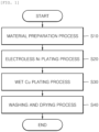
- FIG. 1 is a flowchart illustrating a method of producing vapor chambers according to an embodiment of the present disclosure.
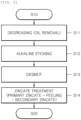
- FIG. 2 is a flowchart subdividing a material preparation process of the processes in FIG. 1 .
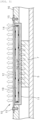
- FIG. 3 is a cross-sectional view illustrating a principle of heat dissipation in a vapor chamber according to an embodiment of the present disclosure.
- the vapor chamber which is designated by reference numeral 10, produced by the method according to the embodiment of the present disclosure is one of heat dissipation components that may use a heat dissipation method based on the concept of excluding the induction of phase change of refrigerant by a compressor.
- the vapor chamber 10 is a representative heat dissipation mechanism designed to cool a specific heating element, which is electrically driven and generates heat, by transferring heat while causing a phase change only by heat supplied from the outside at atmospheric pressure without using a compressor.
- the vapor chamber 10 includes, as illustrated in FIG. 3 , a chamber body plate 11 that has a refrigerant filling space defined to be filled with a refrigerant therein and a vacuum layer 19 formed in the middle thereof to have a predetermined thickness, the chamber body plate 11 having one surface placed in close contact with the heating surface of a heating element 7 mounted on one side of a printed circuit board 5 bonded to the inside of an electronic device and the other surface that is open, a chamber cover plate 12 bonded to shield the other open surface of the chamber body plate 11, and a wick 14 formed as a predetermined thickness layer around the vacuum layer 19 in the refrigerant filling space, which is a space between the chamber body plate 11 and the chamber cover plate 12, and having at least multiple pores through which the refrigerant filled in the refrigerant filling space flows by capillary force.
- the heating element 7 i.e., heat source
- the liquid refrigerant flows toward the wick 14 close to the chamber cover plate 12 while causing a phase change to a gas refrigerant during reaching the vacuum layer 19, and the gas refrigerant causes a phase change to the liquid refrigerant in the wick 14 on the side of the chamber cover plate 12 (i.e., on the heat dissipation side).
- the liquid refrigerant then flows to a region close to the heating element 7 (i.e., to the heat source) by capillary force along the wick 14 having the multiple pores formed therein, so this flow is repeatedly circulated.
- the gas refrigerant flowing toward the chamber body plate 11 may change phase into the liquid refrigerant by exchanging heat with the wick 14, which has a relatively low temperature, on the side of the chamber cover plate 12.
- the heat exchanged may sequentially flow to the wick 14, and the chamber cover plate 12, and the heat transferred to the chamber cover plate 12 may be radiated directly to the outside or may be transferred to a heat sink (not shown) formed integrally with the chamber cover plate 12 for exposure to the outside to be finally radiated to the outside.
- the multiple pores formed in the wick 14 may allow the incoming refrigerant to pass therethrough immediately if it is a gas refrigerant and may function to increase a heat transfer area when the gas refrigerant exchanges relatively low heat with the outside (e.g., the chamber cover plate 12) while flowing.
- the multiple pores may function to quickly induce a phase change to a gas refrigerant while increasing a heat transfer area with the liquid refrigerant and to additionally induce a more active flow of the liquid refrigerant by inducing capillarity according to the surface tension properties of the liquid refrigerant depending on the pore size.
- the refrigerant filled in the refrigerant filling space (i.e., the wick 14) between the chamber body plate 11 and the chamber cover plate 12 may contain one of acetone, ammonia, and distilled water.
- the multiple pores formed in the wick 14 be sized such that the gas refrigerant changes phase into a liquid refrigerant in the wick 14 on the side of the chamber cover plate 12 where the gas refrigerant flows and clusters, and then flows around the periphery of the vacuum layer 19 again toward the wick 14, which is close to the heating element 7 on the inner surface of the chamber body plate 11, and the liquid refrigerant smoothly flows by its own surface tension or capillary force.
- the multiple pores formed in the region of the wick 14 that is in contact with the inner surfaces of the chamber body plate 11 and the chamber cover plate 12 may be provided to communicate with pores between Ni plating layers formed through an electroless Ni plating process, which will be described later, using aluminum powder, and to communicate with a capillary pattern passage (not shown) provided such that the liquid refrigerant after heat exchange flows by capillary force again toward the heating element 7 by surface tension.
- the chamber body plate 11 and the chamber cover plate 12 with the wick 14 provided therebetween may be fastened to a casing 16 of an electronic device or a heat sink, which requires heat dissipation, using fastening screws 15.
- the method of producing vapor chambers includes a material preparation process S10 that prepares each raw material for a chamber body plate 11, a chamber cover plate 12, and a wick 14, wherein the chamber body plate 11 has a refrigerant filling space filled with a refrigerant therein and a vacuum layer 19 with a predetermined thickness, the chamber cover plate 12 shields an open surface to define the refrigerant filling space together with the chamber body plate 11, and the wick 14 is formed in the refrigerant filling space.
- the method may include an electroless Ni plating process S20 that performs electroless Ni plating after a predetermined amount of aluminum (Al) powder, which is the raw material of the wick 14, is placed in a region corresponding to the refrigerant filling space defined by the chamber body plate 11 or the chamber cover plate 12 prepared through the material preparation process S10, a wet Cu plating process S30 that additionally performs Cu plating on the wick 14 formed through the electroless Ni plating process S20 to coat the wick 14 to a predetermined thickness, and a washing and drying process S40 that washes and dries the chamber body plate 11 with the wick 14 formed therein.
- Al aluminum
- the material preparation process S10 may prepare the raw materials for the chamber body plate 11, the chamber cover plate 12, and the wick 14 by performing a degreasing (oil removal) process S11, an alkaline etching process S12, a desmut process S13, and a zincate treatment process S14.
- the degreasing (oil removal) process S11 may be a process of removing foreign substances and organic matter from the aluminum (Al) powder, which is the raw material of the wick 14, using an ultrasonic device.
- the degreasing (oil removal) process S11 may be performed for 1 minute in an atmosphere of temperature of 45 ⁇ 5°C.
- the degreasing (oil removal) process S11 may be performed on the aluminum plate, which is the each raw material of the chamber body plate 11 and the chamber cover plate 12, under the same conditions.
- the alkaline etching process S12 may be a process of immersing the aluminum powder or the aluminum plate, which has been subjected to the degreasing process S11, in an alkaline mixture to treat the surface of the aluminum product with alkali.
- the alkaline etching process S12 may be performed for 10 ⁇ 5 seconds in an atmosphere of temperature of 15 ⁇ 5°C, and the alkaline mixture may have a concentration of 15 ⁇ 5 g/L.
- the alkaline etching process S12 may be, especially for the chamber body plate 11, a process of chemically corroding a region therein corresponding to the refrigerant filling space. In this case, the alkaline etching process S12 may be performed at a temperature of 60 ⁇ 5°C, and the alkaline mixture may have a concentration of 50 ⁇ 5 g/L.
- the desmut process S13 may be a process of removing smut by mixing a sulfuric acid (H 2 SO 4 ) undiluted solution with a chemical containing a special additive of nitric acid (HNO 3 ) type base in a pure (H 2 O) solution.
- a sulfuric acid (H 2 SO 4 ) undiluted solution with a chemical containing a special additive of nitric acid (HNO 3 ) type base in a pure (H 2 O) solution.
- HNO 3 nitric acid
- the sulfuric acid (H 2 SO 4 ) it is preferable to mix the sulfuric acid (H 2 SO 4 ) to have a concentration of 100 ⁇ 10 ml/L with the nitric acid (HNO 3 ) to have a concentration of 60 ⁇ 10 ml/L.
- the zincate treatment process S14 may be generally a pretreatment process when electroless Ni plating is applied to an aluminum alloy product, and may include a primary zincate process of replacing zinc, a zincate peeling process of performing oxide film removal and activation treatment, and a secondary zincate process of replacing zinc again.
- the electroless Ni plating process S20 may be performed in which the aluminum powder, which is the raw material of the wick 14, is bonded in particles (particle units) and cluster units, which are the cluster units of particles, thereby forming multiple pores.
- the electroless Ni plating process S20 may be performed by placing the aluminum (Al) powder, which is the raw material of the wick 14, having a predetermined thickness (or predetermined amount) on the upper side of the chamber cover plate 12 prepared through the material preparation process S10, and then immersing the aluminum powder in the previously prepared nickel salt aqueous solution using the dedicated jig.
- the electroless Ni plating process S20 for the chamber body plate 11 and the chamber cover plate 12 is preferably performed under the same conditions so as to have pores of similar sizes and similar degree of bonding force.
- the electroless Ni plating process S20 may be a process of forming multiple pores while bonding the aluminum powder, which is the raw material of the wick 14, in particle units.
- a Ni plating layer having a predetermined thickness may be formed on the outer surface of the aluminum powder in particle units, in which case the Ni plating layer is also bonded with a number of other surrounding aluminum powders in particle units to form clusters in the size of so-called cluster units, with the consequence that the multiple pores are formed between particles.
- the electroless Ni plating process S20 may be a process of bonding the wick 14 to the inner surface of the chamber body plate 11 or the chamber cover plate 12 made of aluminum, which is the same material as the wick 14, with a predetermined bonding force.
- the above-mentioned Ni plating layer may be formed on the outer surface of the aluminum powder formed in particle and cluster units by the electroless Ni plating process S20, and at the same time, the aluminum powder in particle and cluster units may be bonded to the chamber body plate 11 or the chamber cover plate 12 by the Ni plating layer.
- film treatment or shielding treatment is preferably performed so that the above-mentioned vacuum layer 19 is formed within the chamber body plate 11 with the refrigerant filling space defined therein.
- film treatment or shielding treatment is preferably performed so that the above-mentioned vacuum layer 19 is formed within the chamber body plate 11 with the refrigerant filling space defined therein.
- the wick 14 formed on the chamber cover plate 12 occupies a portion of the volume forming the vacuum layer 19, it will require the same film treatment or shielding treatment as that of the chamber body plate 11.
- aluminum powder may be filled so that the wick 14 is formed as a predetermined thickness layer around the vacuum layer 19, and the above-mentioned electroless Ni plating process S20 and the wet Cu plating process S30 to be described later may be performed, thereby manufacturing the wick 14 having multiple pores of desired specifications.
- the vacuum layer is required to be formed in the chamber cover plate 12 as necessary, aluminum powder may be placed so that the wick 14 is formed as a predetermined thickness layer on the inner surface of the chamber cover plate 12 corresponding to the periphery of the vacuum layer 19 after film treatment or shielding treatment for forming the vacuum layer 19, and the above-mentioned electroless Ni plating process S20 and the wet Cu plating process S30 to be described later may be performed, thereby forming the wick 14 having pores sized similarly to that formed in the chamber body plate 11.
- the chamber cover plate 12 is manufactured separately from the wick 14, and then bonded to shield the open portion of the chamber body plate 11 after the electroless Ni plating process S20 and the wet Cu plating process S30.
- the chamber cover plate 12 may be welded and filled with a liquid refrigerant therein to shield the open portion of the chamber body plate 11 by polishing and chipping away the portion of the wick 14 that comes into contact therewith during bonding for shielding to achieve face-to-face contact with the outer end surface of the wick 14.
- the bonding method of the chamber cover plate 12 to the chamber body plate 11 is not limited to the welding, and any method may be employed as long as the refrigerant filled inside does not leak.
- the method of producing vapor chambers according to the embodiment of the present disclosure may further include the wet Cu plating process S30.
- the wet Cu plating process S30 may be a process of forming a Cu plating layer on the inner surfaces of the wick 14 and the chamber body plate 11 and the inner surfaces of the wick 14 and the chamber cover plate 12 by a typical electroplating method. Specifically, the wet Cu plating process S30 may be a process of additionally forming a Cu plating layer on the Ni plating layer on the surface of the wick 14 formed through the electroless Ni plating process S20 to form the multiple pores sized such that the refrigerant filled in the refrigerant filling space flows by capillarity.
- the wet Cu plating process S30 is a process of further increasing the predetermined bonding force of the wick 14 to the chamber body plate 11 by the Ni plating layer formed through the electroless Ni plating process S20 and the predetermined bonding force of the wick 14 to the chamber cover plate 12 by the Cu plating layer.
- the wet Cu plating process S30 may additionally form the Cu plating layer on the outer surface of the Ni plating layer of particles that still remain in particle units even through the electroless Ni plating process S20 to involve in bonding in cluster units, or may additionally form the Cu plating layer on the outer surface of the Ni plating layer to add the bonding force to the inner surface of the chamber body plate 11 or the chamber cover plate 12.
- the increase in the predetermined bonding force of the wick 14 to the chamber body plate 11 and the predetermined bonding force of the wick 14 to the chamber cover plate 12 may minimize separation and detachment between the wick 14 and the chamber body plate 11 and between the wick 14 and the chamber cover plate 12.
- the heat from the heating element 7 may be transferred via the chamber body plate 11 to the wick 14 with high thermal conductivity, which may significantly increase overall thermal conductivity.
- the vapor chamber 10 according to the embodiment of the present disclosure produced by the above-mentioned method may be defined as follows. This definition should be an important standard in interpreting the true scope of rights of the present disclosure.
- the vapor chamber 10 includes the chamber body plate 11 having one surface placed in close contact with the heating surface of the heating element and the other surface that is open, and having the refrigerant filling space filled with a refrigerant therein and defined to have a predetermined thickness, the chamber cover plate 12 bonded to shield the other open surface of the chamber body plate 11, and the wick 14 formed as a predetermined thickness layer around the vacuum layer 19 in the refrigerant filling space, which is a space between the chamber body plate 11 and the chamber cover plate 12, and having at least the multiple pores through which the refrigerant (especially, liquid refrigerant) filled in the refrigerant filling space flows by appropriate capillary force.
- the chamber body plate 11 having one surface placed in close contact with the heating surface of the heating element and the other surface that is open, and having the refrigerant filling space filled with a refrigerant therein and defined to have a predetermined thickness
- the chamber cover plate 12 bonded to shield the other open surface of the chamber body plate 11, and the wick 14
- the wick 14 may have the multiple pores formed through the electroless Ni plating process S20 with the aluminum powder filled in the refrigerant filling space.
- the multiple pores formed in the wick 14 may be formed by the Ni plating layer formed on the outer surface of the aluminum powder in particles (particle units) or cluster units.
- the Cu plating layer may be additionally formed on the outer surface of the Ni plating layer through the wet Cu plating process S30 to form the multiple pores sized such that the refrigerant flows by capillarity.
- the chamber body plate 11 and the chamber cover plate 12 may be made of an aluminum material (in the form of a plate), which is the same material as the wick 14 before the electroless Ni plating process S20.
- the wick 14 may be bonded to the inner surfaces of the chamber body plate 11 and the chamber cover plate 12 with a predetermined bonding force through the electroless Ni plating process S20.
- the predetermined bonding force between the inner surface of the chamber body plate 11 and the wick 14 and between the inner surface of the chamber cover plate 12 and the wick 14 may be further increased by addition of the wet Cu plating process S30. Therefore, as described above, the heat generated by the heating element 7 can be smoothly radiated to the outside while maintaining higher thermal conductivity.
- an additional bonding process may be performed of welding the chamber body plate 11 and the chamber cover plate 12 so that the wick 14 is in surface contact with the chamber body plate 11 and the chamber cover plate 12.
- the wick 14 is filled within the chamber body plate 11 and then the portions thereof are bonded to each other through the above-mentioned electroless Ni plating process S20 and wet Cu plating process S30. Accordingly, a bonding process may also be employed of welding only the chamber cover plate 12.
- the portion of the wick 14 in contact with the inner surface of the chamber cover plate 12 may have an uneven outer surface since the multiple pores are formed simply through the Ni plating process S20. Accordingly, after the outer portion of the wick 14 is cut to be flat, the portion of the wick 14 in contact with the inner surface of the chamber cover plate 12 may be machined using a laser processing machine (not shown) to form a predetermined capillary pattern passage (not shown) in communication with the multiple pores.
- the capillary pattern passage may be formed by laser processing between the inner surface of the chamber cover plate 12 and the outer surface of the wick 14 while communicating with the multiple pores, to provide a movement path by capillary force in an opposite direction where the heating element is provided when the refrigerant filled in the chamber body plate 11 changes phase into a liquid refrigerant due to heat exchange.
- the chamber cover plate 12 may be bonded by one of the above-mentioned welding and various bonding methods to cover the open outer surface of the chamber body plate 11 so that the inner surface of the chamber cover plate 12 is in surface contact with the outer surface of the wick 14 on which the capillary pattern passage is machined.
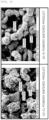
- FIG. 4 is a photomicrograph for comparing a particle size, a cluster size, and a pore size between (a) a Cu powder sintered product manufactured through the sintering process and (b) an Al powder sintered product manufactured by the method according to the embodiment of the present disclosure.
- FIG. 5 is a photomicrograph for comparing an overall inter-particle distance between (a) the Cu powder sintered product manufactured through the sintering process and (b) the Al powder sintered product manufactured by the method according to the embodiment of the present disclosure.
- FIG. 4(a) is a photograph magnified 300 times of the Cu powder sintered product through the typical sintering process by a microscope, and it can be visually seen that individual particles are melt-bonded.
- the particle size and the cluster size which is a combination of particles, are relatively large compared to those in FIG. 4(b) . Due to melt bonding between particles, most of the pores within the cluster are closed, which may cause a decrease in capillary force and thus reduce overall heat conduction performance.
- FIG. 4(b) is a photograph magnified 300 times of the wick 14 manufactured by the method according to the embodiment of the present disclosure.
- FIG. 4(b) it can be visually that the capillary force is relatively improved since individual particles are chemically bonded, the pores within the cluster are open, and the gap between clusters is also open.
- the wick 14 manufactured by the method according to the embodiment of the present disclosure may have a size of approximately 100 ⁇ m and have a size (approximately 130 ⁇ m) of particles of the sintered product illustrated in FIG. 5(a) . Accordingly, it can be seen that the wick 14 generally forms larger pores when forming a cluster, thereby improving capillary force.
- the present disclosure is directed to a vapor chamber with improved thermal conductivity, which is capable of completely excluding a complicated and energy-consuming sintering process and having multiple pores whose size is suitable for flow according to capillarity of refrigerant, and a method of producing the same.
Landscapes
- Chemical & Material Sciences (AREA)
- Engineering & Computer Science (AREA)
- Mechanical Engineering (AREA)
- Chemical Kinetics & Catalysis (AREA)
- Materials Engineering (AREA)
- Metallurgy (AREA)
- Organic Chemistry (AREA)
- General Chemical & Material Sciences (AREA)
- Physics & Mathematics (AREA)
- Thermal Sciences (AREA)
- Life Sciences & Earth Sciences (AREA)
- Sustainable Development (AREA)
- General Engineering & Computer Science (AREA)
- Electrochemistry (AREA)
- Inorganic Chemistry (AREA)
- Microelectronics & Electronic Packaging (AREA)
- Chemically Coating (AREA)
- Cooling Or The Like Of Electrical Apparatus (AREA)
Abstract
Description
- The present disclosure relates to a vapor chamber and a method of producing the same, and more particularly, to a vapor chamber with improved heat conduction performance, in which a wick is able to be formed easily having a desired pore size without subjecting to a complicated sintering process, and a method of producing the same.
- While electronic devices have seen remarkable growth in terms of improvements in performance recently, the amount of system heat generated within the devices has also increased relatively significantly in addition to improved performance. Besides, the devices have also been continuously reduced in size and attempts have been made to concentrate circuits within smaller confined spaces. Hence, the heat generated from these highly integrated components (heating elements) may degrade or deteriorate performance of the devices, making it an increasingly major issue in the industry of manufacture of electronic devices to effectively dissipate system heat.
- To solve this issue, heat sinks are commonly used that may each be basically composed of a base plate to receive heat by direct contact with a heat source to be cooled and a plurality of cooling fins protruding from the base plate to transfer heat from the base plate to the air therearound. These heat sinks are being actively researched in the materials and designs thereof according to the intended purpose thereof, but in common, they are being developed to increase the area in contact with air by maximizing the surface areas of the cooling fins for effective dissipation of heat.
- Such a heat sink is one of heat dissipation mechanisms that mainly function to radiate system heat within electronic devices to the outside rather than in direct thermal contact with surfaces of heating elements. When a heating element is spaced far away from a base plate, effective heat conduction is difficult. Accordingly, a heat pipe and a vapor chamber are often employed as heat conductors that transfer heat by direct thermal contact with surfaces of heating elements.
- The heat pipe and the vapor chamber are distinguished depending on the external appearance thereof, namely, whether to have a pipe shape or a plate shape. In particular, the vapor chamber is a heat transfer medium, which has one surface in direct thermal contact with the heating surface of a heating element and the other surface in thermal contact with outdoor air or the surface of a heat dissipation mechanism such as a heat sink and is provided with a wick having multiple pores therein to transfer heat from the heating element through heat conduction between one surface and the other surface while moving a refrigerant filled therein through the wick by capillarity.
- Here, the multiple pores of the wick for moving the refrigerant by capillarity are typically formed through a sintering process of sintering Cu powder at a predetermined temperature. The gap between particles in the wick formed through the sintering process is narrow to cause a small pore size, which may lead to less capillary force than required.
- In addition, since the raw material of the wick is limited to Cu powder suitable for the sintering temperature of the sintering process, it may be difficult to employ other materials with excellent thermal conductivity.
- Moreover, if the raw materials for the wick, the chamber body plate, and the chamber cover plate are different, the sintering bond strength therebetween may decrease to space them apart, resulting in deterioration in thermal conductivity.
- The present disclosure has been made in view of the above-mentioned problems, and an object of the present disclosure is to provide a vapor chamber with improved thermal conductivity, which is capable of completely excluding a complicated and energy-consuming sintering process and having multiple pores whose size is suitable for flow according to capillarity of refrigerant, and a method of producing the same.
- The present disclosure is not limited to the above-mentioned object, and other objects of the present disclosure can be clearly understood by those skilled in the art to which the present disclosure pertains from the following description.
- In accordance with an aspect of the present disclosure, there is provided a vapor chamber that includes a chamber body plate having one surface placed in close contact with a heating surface of a heating element and the other surface that is open, the chamber body plate having a refrigerant filling space filled with a refrigerant therein and defined to have a predetermined thickness, a chamber cover plate bonded to shield the other open surface of the chamber body plate, and a wick formed in the refrigerant filling space, which is a space between the chamber body plate and the chamber cover plate, the wick having at least multiple pores through which the refrigerant filled in the refrigerant filling space flows, wherein the wick includes a Ni plating layer formed on an outer surface of aluminum powder bonded in particle units.
- The chamber body plate and the chamber cover plate may be made of aluminum, which is the same material as the wick before an electroless Ni plating process.
- The chamber body plate and the wick or the chamber cover plate and the wick may be bonded with a predetermined bonding force through the electroless Ni plating process.
- The wick may further include a Cu plating layer formed on an outer surface of the Ni plating layer.
- The predetermined bonding force between an inner surface of the chamber body plate and the wick may be further increased by addition of a wet Cu plating process to form the Cu plating layer.
- The multiple pores formed in the wick may be sized such that the refrigerant flows through capillarity by the Cu plating layer formed through the wet Cu plating process.
- In accordance with another aspect of the present disclosure, there is provided a method of producing vapor chambers, which includes a material preparation process of preparing each raw material for a chamber body plate, a chamber cover plate, and a wick, the chamber body plate having a refrigerant filling space filled with a refrigerant therein, the chamber cover plate configured to shield an open surface to define the refrigerant filling space together with the chamber body plate, the wick being formed in the refrigerant filling space, and an electroless Ni plating process of performing electroless Ni plating after a predetermined amount of aluminum powder, which is the raw material of the wick, is placed in a region corresponding to the refrigerant filling space defined by the chamber body plate or the chamber cover plate prepared through the material preparation process.
- The method may further include a wet Cu plating process of additionally performing Cu plating on the wick formed through the electroless Ni plating process.
- The material preparation process may be a process of preceding a zincate treatment process after forming an empty space corresponding to the refrigerant filling space by etching at least one of the chamber body plate and the chamber cover plate prepared in the form of an aluminum plate so that the wick is formed in the refrigerant filling space.
- The electroless Ni plating process may be a process of forming the multiple pores while bonding the aluminum powder, and of simultaneously bonding the wick to an inner surface of the chamber body plate or the chamber cover plate made of aluminum, which is the same material as the wick, with a predetermined bonding force.
- The wet Cu plating process may be a process of plating a copper layer on a surface of the wick formed through the electroless Ni plating process to form the multiple pores sized such that the refrigerant filled in the refrigerant filling space flows by capillarity.
- The wet Cu plating process may be a process of further increasing a predetermined bonding force of the wick to the chamber body plate or of the wick to the chamber cover plate made through the electroless Ni plating process.
- After the electroless Ni plating process and the wet Cu plating process are performed separately on the chamber body plate and the chamber cover plate, an additional bonding process may be performed of welding the chamber body plate and the chamber cover plate so that the wick is in surface contact with the chamber body plate and the chamber cover plate.
- A vapor chamber and a method of producing the same according to exemplary embodiments of present disclosure can achieve various effects as follows.
- Firstly, energy consumption can be minimized since a sintering process may be completely excluded in the formation of multiple pores in a wick.
- Secondly, it is possible to increase capillary force by increasing the particle gap between aluminum powders bonded through electroless Ni plating and wet Cu plating processes to enable the formation of relatively larger pores than the pores formed through the sintering process.
- Thirdly, it is possible to enhance overall thermal conductivity through the improvement in fluidity of filling refrigerant by increasing capillary force.
-
-
FIG. 1 is a flowchart illustrating a method of producing vapor chambers according to an embodiment of the present disclosure. -
FIG. 2 is a flowchart subdividing a material preparation process of the processes inFIG. 1 . -
FIG. 3 is a cross-sectional view illustrating a principle of heat dissipation in a vapor chamber according to an embodiment of the present disclosure. -
FIG. 4 is a photomicrograph for comparing a particle size, a cluster size, and a pore size between (a) a Cu powder sintered product manufactured through a sintering process and (b) an Al powder sintered product manufactured by the method according to the embodiment of the present disclosure. -
FIG. 5 is a photomicrograph for comparing an overall inter-particle distance between (a) the Cu powder sintered product manufactured through the sintering process and (b) the Al powder sintered product manufactured by the method according to the embodiment of the present disclosure. -
- 5: printed circuit board 7: heating element
- 10: vapor chamber 11: chamber body plate
- 12: chamber cover plate 14: wick
- 15: fastening screw 16: casing
- S10: material preparation process S11: degreasing process
- S12: alkaline etching process S13: desmut process
- S14: zincate treatment process S20: electroless Ni plating process
- S30: wet Cu plating process S40: washing and drying process
- Hereinafter, a vapor chamber and a method of producing the same according to exemplary embodiments of the present disclosure will be described in detail with reference to the accompanying drawings.
- It should be noted that reference numerals are added to the components of the accompanying drawings to facilitate understanding of the embodiments described below and the same reference numbers will be used throughout the drawings to refer to the same or like parts wherever possible. In certain embodiments, detailed descriptions of constructions or functions well known in the art may be omitted to avoid obscuring appreciation of the disclosure by a person of ordinary skill in the art.
- The terms such as "first", "second", "A", "B", " (a) ", and " (b)" may be used herein to describe components in the embodiments of the present disclosure. These terms are not used to define an essence, order or sequence of a corresponding component but used merely to distinguish the corresponding component from other component(s). Unless otherwise defined, all terms, including technical and scientific terms, used herein have the same meaning as commonly understood by one of ordinary skill in the art. It will be further understood that terms, such as those defined in commonly used dictionaries, should be interpreted as having a meaning that is consistent with their meaning in the context of the relevant art and the present disclosure, and will not be interpreted in an idealized or overly formal sense unless expressly so defined herein.
-
FIG. 1 is a flowchart illustrating a method of producing vapor chambers according to an embodiment of the present disclosure.FIG. 2 is a flowchart subdividing a material preparation process of the processes inFIG. 1 .FIG. 3 is a cross-sectional view illustrating a principle of heat dissipation in a vapor chamber according to an embodiment of the present disclosure. - First, the principle of heat dissipation in the vapor chamber according to the embodiment of the present disclosure will be described with reference to
FIG. 3 . - The vapor chamber, which is designated by
reference numeral 10, produced by the method according to the embodiment of the present disclosure is one of heat dissipation components that may use a heat dissipation method based on the concept of excluding the induction of phase change of refrigerant by a compressor. Thevapor chamber 10 is a representative heat dissipation mechanism designed to cool a specific heating element, which is electrically driven and generates heat, by transferring heat while causing a phase change only by heat supplied from the outside at atmospheric pressure without using a compressor. - More specifically, the
vapor chamber 10 includes, as illustrated inFIG. 3 , achamber body plate 11 that has a refrigerant filling space defined to be filled with a refrigerant therein and avacuum layer 19 formed in the middle thereof to have a predetermined thickness, thechamber body plate 11 having one surface placed in close contact with the heating surface of aheating element 7 mounted on one side of a printedcircuit board 5 bonded to the inside of an electronic device and the other surface that is open, achamber cover plate 12 bonded to shield the other open surface of thechamber body plate 11, and awick 14 formed as a predetermined thickness layer around thevacuum layer 19 in the refrigerant filling space, which is a space between thechamber body plate 11 and thechamber cover plate 12, and having at least multiple pores through which the refrigerant filled in the refrigerant filling space flows by capillary force. - As illustrated in
FIG. 3 , when heat is transferred to the liquid refrigerant inside through thechamber body plate 11 by the heating element 7 (i.e., heat source) provided on one side of thechamber body plate 11 in the thickness direction thereof, the liquid refrigerant flows toward thewick 14 close to thechamber cover plate 12 while causing a phase change to a gas refrigerant during reaching thevacuum layer 19, and the gas refrigerant causes a phase change to the liquid refrigerant in thewick 14 on the side of the chamber cover plate 12 (i.e., on the heat dissipation side). The liquid refrigerant then flows to a region close to the heating element 7 (i.e., to the heat source) by capillary force along thewick 14 having the multiple pores formed therein, so this flow is repeatedly circulated. - In this case, the gas refrigerant flowing toward the chamber body plate 11 (i.e., to the heat dissipation side) may change phase into the liquid refrigerant by exchanging heat with the
wick 14, which has a relatively low temperature, on the side of thechamber cover plate 12. At the same time, the heat exchanged may sequentially flow to thewick 14, and thechamber cover plate 12, and the heat transferred to thechamber cover plate 12 may be radiated directly to the outside or may be transferred to a heat sink (not shown) formed integrally with thechamber cover plate 12 for exposure to the outside to be finally radiated to the outside. - Here, the multiple pores formed in the
wick 14 may allow the incoming refrigerant to pass therethrough immediately if it is a gas refrigerant and may function to increase a heat transfer area when the gas refrigerant exchanges relatively low heat with the outside (e.g., the chamber cover plate 12) while flowing. On the other hand, if the incoming refrigerant is a liquid refrigerant, the multiple pores may function to quickly induce a phase change to a gas refrigerant while increasing a heat transfer area with the liquid refrigerant and to additionally induce a more active flow of the liquid refrigerant by inducing capillarity according to the surface tension properties of the liquid refrigerant depending on the pore size. - For reference, the refrigerant filled in the refrigerant filling space (i.e., the wick 14) between the
chamber body plate 11 and thechamber cover plate 12 may contain one of acetone, ammonia, and distilled water. - As illustrated in
FIG. 3 , it is preferable that the multiple pores formed in thewick 14 be sized such that the gas refrigerant changes phase into a liquid refrigerant in thewick 14 on the side of thechamber cover plate 12 where the gas refrigerant flows and clusters, and then flows around the periphery of thevacuum layer 19 again toward thewick 14, which is close to theheating element 7 on the inner surface of thechamber body plate 11, and the liquid refrigerant smoothly flows by its own surface tension or capillary force. - Here, the multiple pores formed in the region of the
wick 14 that is in contact with the inner surfaces of thechamber body plate 11 and thechamber cover plate 12 may be provided to communicate with pores between Ni plating layers formed through an electroless Ni plating process, which will be described later, using aluminum powder, and to communicate with a capillary pattern passage (not shown) provided such that the liquid refrigerant after heat exchange flows by capillary force again toward theheating element 7 by surface tension. - Meanwhile, the
chamber body plate 11 and thechamber cover plate 12 with thewick 14 provided therebetween may be fastened to acasing 16 of an electronic device or a heat sink, which requires heat dissipation, using fastening screws 15. - Hereinafter, the important technical features of the method of forming the
wick 14 provided in thevapor chamber 10 will be described in the embodiment of the present disclosure. - More specifically, referring to
FIGS. 1 and2 , the method of producing vapor chambers according to the embodiment of the present disclosure includes a material preparation process S10 that prepares each raw material for achamber body plate 11, achamber cover plate 12, and awick 14, wherein thechamber body plate 11 has a refrigerant filling space filled with a refrigerant therein and avacuum layer 19 with a predetermined thickness, thechamber cover plate 12 shields an open surface to define the refrigerant filling space together with thechamber body plate 11, and thewick 14 is formed in the refrigerant filling space. - In addition, the method may include an electroless Ni plating process S20 that performs electroless Ni plating after a predetermined amount of aluminum (Al) powder, which is the raw material of the
wick 14, is placed in a region corresponding to the refrigerant filling space defined by thechamber body plate 11 or thechamber cover plate 12 prepared through the material preparation process S10, a wet Cu plating process S30 that additionally performs Cu plating on thewick 14 formed through the electroless Ni plating process S20 to coat thewick 14 to a predetermined thickness, and a washing and drying process S40 that washes and dries thechamber body plate 11 with thewick 14 formed therein. - The material preparation process S10, as illustrated in
FIG. 2 , may prepare the raw materials for thechamber body plate 11, thechamber cover plate 12, and thewick 14 by performing a degreasing (oil removal) process S11, an alkaline etching process S12, a desmut process S13, and a zincate treatment process S14. - The degreasing (oil removal) process S11 may be a process of removing foreign substances and organic matter from the aluminum (Al) powder, which is the raw material of the
wick 14, using an ultrasonic device. Here, the degreasing (oil removal) process S11 may be performed for 1 minute in an atmosphere of temperature of 45 ± 5°C. The degreasing (oil removal) process S11 may be performed on the aluminum plate, which is the each raw material of thechamber body plate 11 and thechamber cover plate 12, under the same conditions. - The alkaline etching process S12 may be a process of immersing the aluminum powder or the aluminum plate, which has been subjected to the degreasing process S11, in an alkaline mixture to treat the surface of the aluminum product with alkali. Here, the alkaline etching process S12 may be performed for 10 ± 5 seconds in an atmosphere of temperature of 15 ± 5°C, and the alkaline mixture may have a concentration of 15 ± 5 g/L. The alkaline etching process S12 may be, especially for the
chamber body plate 11, a process of chemically corroding a region therein corresponding to the refrigerant filling space. In this case, the alkaline etching process S12 may be performed at a temperature of 60 ± 5°C, and the alkaline mixture may have a concentration of 50 ± 5 g/L. - The desmut process S13 may be a process of removing smut by mixing a sulfuric acid (H2SO4) undiluted solution with a chemical containing a special additive of nitric acid (HNO3) type base in a pure (H2O) solution. In particular, when an aluminum material is etched with the above-mentioned alkaline mixture, the etching speed of an alloy component such as Mg, Cu, Si, or Mn differs from the etching speed of the base material, resulting in the formation of black smut on the surface thereof. Accordingly, the above-mentioned desmut process S13 using high-concentration nitric acid and sulfuric acid undiluted solutions is essential for removal of the black smut.
- Here, it is preferable to mix the sulfuric acid (H2SO4) to have a concentration of 100 ± 10 ml/L with the nitric acid (HNO3) to have a concentration of 60 ± 10 ml/L.
- The zincate treatment process S14 may be generally a pretreatment process when electroless Ni plating is applied to an aluminum alloy product, and may include a primary zincate process of replacing zinc, a zincate peeling process of performing oxide film removal and activation treatment, and a secondary zincate process of replacing zinc again.
- When the aluminum (Al) powder, which is the raw material of the
wick 14 within thechamber body plate 11 prepared through the material preparation process S10, is compressed and filled in a region corresponding to the refrigerant filling space, and is then immersed in a previously prepared nickel salt aqueous solution using a dedicated jig, the electroless Ni plating process S20 may be performed in which the aluminum powder, which is the raw material of thewick 14, is bonded in particles (particle units) and cluster units, which are the cluster units of particles, thereby forming multiple pores. - Likewise, the electroless Ni plating process S20 may be performed by placing the aluminum (Al) powder, which is the raw material of the
wick 14, having a predetermined thickness (or predetermined amount) on the upper side of thechamber cover plate 12 prepared through the material preparation process S10, and then immersing the aluminum powder in the previously prepared nickel salt aqueous solution using the dedicated jig. In this case, the electroless Ni plating process S20 for thechamber body plate 11 and thechamber cover plate 12 is preferably performed under the same conditions so as to have pores of similar sizes and similar degree of bonding force. - Here, the electroless Ni plating process S20 may be a process of forming multiple pores while bonding the aluminum powder, which is the raw material of the
wick 14, in particle units. - In other words, a Ni plating layer having a predetermined thickness may be formed on the outer surface of the aluminum powder in particle units, in which case the Ni plating layer is also bonded with a number of other surrounding aluminum powders in particle units to form clusters in the size of so-called cluster units, with the consequence that the multiple pores are formed between particles.
- In addition, the electroless Ni plating process S20 may be a process of bonding the
wick 14 to the inner surface of thechamber body plate 11 or thechamber cover plate 12 made of aluminum, which is the same material as thewick 14, with a predetermined bonding force. - In other words, the above-mentioned Ni plating layer may be formed on the outer surface of the aluminum powder formed in particle and cluster units by the electroless Ni plating process S20, and at the same time, the aluminum powder in particle and cluster units may be bonded to the
chamber body plate 11 or thechamber cover plate 12 by the Ni plating layer. - In this case, film treatment or shielding treatment is preferably performed so that the above-mentioned
vacuum layer 19 is formed within thechamber body plate 11 with the refrigerant filling space defined therein. In addition, even when thewick 14 formed on thechamber cover plate 12 occupies a portion of the volume forming thevacuum layer 19, it will require the same film treatment or shielding treatment as that of thechamber body plate 11. - More specifically, after the
chamber body plate 11 is processed to form the above-mentionedvacuum layer 19 in the space within thechamber body plate 11, aluminum powder may be filled so that thewick 14 is formed as a predetermined thickness layer around thevacuum layer 19, and the above-mentioned electroless Ni plating process S20 and the wet Cu plating process S30 to be described later may be performed, thereby manufacturing thewick 14 having multiple pores of desired specifications. - In addition, if the vacuum layer is required to be formed in the
chamber cover plate 12 as necessary, aluminum powder may be placed so that thewick 14 is formed as a predetermined thickness layer on the inner surface of thechamber cover plate 12 corresponding to the periphery of thevacuum layer 19 after film treatment or shielding treatment for forming thevacuum layer 19, and the above-mentioned electroless Ni plating process S20 and the wet Cu plating process S30 to be described later may be performed, thereby forming thewick 14 having pores sized similarly to that formed in thechamber body plate 11. - In particular, the
chamber cover plate 12 is manufactured separately from thewick 14, and then bonded to shield the open portion of thechamber body plate 11 after the electroless Ni plating process S20 and the wet Cu plating process S30. In this regard, thechamber cover plate 12 may be welded and filled with a liquid refrigerant therein to shield the open portion of thechamber body plate 11 by polishing and chipping away the portion of thewick 14 that comes into contact therewith during bonding for shielding to achieve face-to-face contact with the outer end surface of thewick 14. - In this case, the bonding method of the
chamber cover plate 12 to thechamber body plate 11 is not limited to the welding, and any method may be employed as long as the refrigerant filled inside does not leak. - Meanwhile, the
wick 14 manufactured through the electroless Ni plating process S20 is bonded to the inner surface of thechamber body plate 11 or thechamber cover plate 12 with a predetermined bonding force as described above, but the bonding force may be small compared to when manufacturing thewick 14 through a sintering process. Therefore, the method of producing vapor chambers according to the embodiment of the present disclosure may further include the wet Cu plating process S30. - The wet Cu plating process S30 may be a process of forming a Cu plating layer on the inner surfaces of the
wick 14 and thechamber body plate 11 and the inner surfaces of thewick 14 and thechamber cover plate 12 by a typical electroplating method. Specifically, the wet Cu plating process S30 may be a process of additionally forming a Cu plating layer on the Ni plating layer on the surface of thewick 14 formed through the electroless Ni plating process S20 to form the multiple pores sized such that the refrigerant filled in the refrigerant filling space flows by capillarity. - It may also be understood that the wet Cu plating process S30 is a process of further increasing the predetermined bonding force of the
wick 14 to thechamber body plate 11 by the Ni plating layer formed through the electroless Ni plating process S20 and the predetermined bonding force of thewick 14 to thechamber cover plate 12 by the Cu plating layer. In other words, the wet Cu plating process S30 may additionally form the Cu plating layer on the outer surface of the Ni plating layer of particles that still remain in particle units even through the electroless Ni plating process S20 to involve in bonding in cluster units, or may additionally form the Cu plating layer on the outer surface of the Ni plating layer to add the bonding force to the inner surface of thechamber body plate 11 or thechamber cover plate 12. - The increase in the predetermined bonding force of the
wick 14 to thechamber body plate 11 and the predetermined bonding force of thewick 14 to thechamber cover plate 12 may minimize separation and detachment between thewick 14 and thechamber body plate 11 and between thewick 14 and thechamber cover plate 12. Thus, the heat from theheating element 7 may be transferred via thechamber body plate 11 to thewick 14 with high thermal conductivity, which may significantly increase overall thermal conductivity. - Therefore, the
vapor chamber 10 according to the embodiment of the present disclosure produced by the above-mentioned method may be defined as follows. This definition should be an important standard in interpreting the true scope of rights of the present disclosure. - In other words, the
vapor chamber 10 according to the embodiment of the present disclosure includes thechamber body plate 11 having one surface placed in close contact with the heating surface of the heating element and the other surface that is open, and having the refrigerant filling space filled with a refrigerant therein and defined to have a predetermined thickness, thechamber cover plate 12 bonded to shield the other open surface of thechamber body plate 11, and thewick 14 formed as a predetermined thickness layer around thevacuum layer 19 in the refrigerant filling space, which is a space between thechamber body plate 11 and thechamber cover plate 12, and having at least the multiple pores through which the refrigerant (especially, liquid refrigerant) filled in the refrigerant filling space flows by appropriate capillary force. - The
wick 14 may have the multiple pores formed through the electroless Ni plating process S20 with the aluminum powder filled in the refrigerant filling space. The multiple pores formed in thewick 14 may be formed by the Ni plating layer formed on the outer surface of the aluminum powder in particles (particle units) or cluster units. As described above, the Cu plating layer may be additionally formed on the outer surface of the Ni plating layer through the wet Cu plating process S30 to form the multiple pores sized such that the refrigerant flows by capillarity. - In addition, the
chamber body plate 11 and thechamber cover plate 12 may be made of an aluminum material (in the form of a plate), which is the same material as thewick 14 before the electroless Ni plating process S20. As described above, thewick 14 may be bonded to the inner surfaces of thechamber body plate 11 and thechamber cover plate 12 with a predetermined bonding force through the electroless Ni plating process S20. - Furthermore, the predetermined bonding force between the inner surface of the
chamber body plate 11 and thewick 14 and between the inner surface of thechamber cover plate 12 and thewick 14 may be further increased by addition of the wet Cu plating process S30. Therefore, as described above, the heat generated by theheating element 7 can be smoothly radiated to the outside while maintaining higher thermal conductivity. - Meanwhile, although not illustrated, it is natural that, after the electroless Ni plating process S20 and the wet Cu plating process S30 are performed separately on the
chamber body plate 11 and thechamber cover plate 12, an additional bonding process may be performed of welding thechamber body plate 11 and thechamber cover plate 12 so that thewick 14 is in surface contact with thechamber body plate 11 and thechamber cover plate 12. - However, more advantageously, the
wick 14 is filled within thechamber body plate 11 and then the portions thereof are bonded to each other through the above-mentioned electroless Ni plating process S20 and wet Cu plating process S30. Accordingly, a bonding process may also be employed of welding only thechamber cover plate 12. - In this case, although not illustrated in the drawings, the portion of the
wick 14 in contact with the inner surface of thechamber cover plate 12 may have an uneven outer surface since the multiple pores are formed simply through the Ni plating process S20. Accordingly, after the outer portion of thewick 14 is cut to be flat, the portion of thewick 14 in contact with the inner surface of thechamber cover plate 12 may be machined using a laser processing machine (not shown) to form a predetermined capillary pattern passage (not shown) in communication with the multiple pores. - The capillary pattern passage may be formed by laser processing between the inner surface of the
chamber cover plate 12 and the outer surface of thewick 14 while communicating with the multiple pores, to provide a movement path by capillary force in an opposite direction where the heating element is provided when the refrigerant filled in thechamber body plate 11 changes phase into a liquid refrigerant due to heat exchange. - After the capillary pattern passage is machined on the outer surface of the
wick 14 by the laser processing machine, thechamber cover plate 12 may be bonded by one of the above-mentioned welding and various bonding methods to cover the open outer surface of thechamber body plate 11 so that the inner surface of thechamber cover plate 12 is in surface contact with the outer surface of thewick 14 on which the capillary pattern passage is machined. -
FIG. 4 is a photomicrograph for comparing a particle size, a cluster size, and a pore size between (a) a Cu powder sintered product manufactured through the sintering process and (b) an Al powder sintered product manufactured by the method according to the embodiment of the present disclosure.FIG. 5 is a photomicrograph for comparing an overall inter-particle distance between (a) the Cu powder sintered product manufactured through the sintering process and (b) the Al powder sintered product manufactured by the method according to the embodiment of the present disclosure. -
FIG. 4(a) is a photograph magnified 300 times of the Cu powder sintered product through the typical sintering process by a microscope, and it can be visually seen that individual particles are melt-bonded. In addition, it can be seen fromFIG. 4 that the particle size and the cluster size, which is a combination of particles, are relatively large compared to those inFIG. 4(b) . Due to melt bonding between particles, most of the pores within the cluster are closed, which may cause a decrease in capillary force and thus reduce overall heat conduction performance. - On the other hand,
FIG. 4(b) is a photograph magnified 300 times of thewick 14 manufactured by the method according to the embodiment of the present disclosure. InFIG. 4(b) , it can be visually that the capillary force is relatively improved since individual particles are chemically bonded, the pores within the cluster are open, and the gap between clusters is also open. - In other words, the
wick 14 manufactured by the method according to the embodiment of the present disclosure, as illustrated inFIG. 5(b) , may have a size of approximately 100 µm and have a size (approximately 130 µm) of particles of the sintered product illustrated inFIG. 5(a) . Accordingly, it can be seen that thewick 14 generally forms larger pores when forming a cluster, thereby improving capillary force. - As described above, in the vapor chamber and the method of producing the same according to the embodiments of the present disclosure, it is somewhat difficult to control porosity, but it is possible to significantly enhance overall heat conduction performance by forming the multiple pores with improved capillary force compared to the wick formed through the sintering process as well as by improving bonding force to the
chamber body plate 11 or thechamber cover plate 12. - The vapor chamber and the method of producing the same according to the exemplary embodiments of the present disclosure have been described above in detail with reference to the accompanying drawings. However, the exemplary embodiments of the present disclosure should not be construed as limiting the technical idea of the disclosure. It will be apparent to those skilled in the art that the scope of the present disclosure is limited only by the appended claims and various variations and modifications may be made without departing from the spirit and scope of the disclosure. Therefore, the true scope of rights of the present disclosure should be defined by the appended claims.
- The present disclosure is directed to a vapor chamber with improved thermal conductivity, which is capable of completely excluding a complicated and energy-consuming sintering process and having multiple pores whose size is suitable for flow according to capillarity of refrigerant, and a method of producing the same.
Claims (13)
- A vapor chamber comprising:a chamber body plate having one surface placed in close contact with a heating surface of a heating element and the other surface that is open, the chamber body plate having a refrigerant filling space filled with a refrigerant therein and defined to have a predetermined thickness;a chamber cover plate bonded to shield the other open surface of the chamber body plate; anda wick formed in the refrigerant filling space, which is a space between the chamber body plate and the chamber cover plate, the wick having at least multiple pores through which the refrigerant filled in the refrigerant filling space flows,wherein the wick comprises a Ni plating layer formed on an outer surface of aluminum powder bonded in particle units.
- The vapor chamber according to claim 1, wherein the chamber body plate and the chamber cover plate are made of aluminum, which is the same material as the wick before an electroless Ni plating process.
- The vapor chamber according to claim 2, wherein the chamber body plate and the wick or the chamber cover plate and the wick are bonded with a predetermined bonding force through the electroless Ni plating process.
- The vapor chamber according to claim 2, wherein the wick further comprises a Cu plating layer formed on an outer surface of the Ni plating layer.
- The vapor chamber according to claim 4, wherein a predetermined bonding force between an inner surface of the chamber body plate and the wick is further increased by addition of a wet Cu plating process to form the Cu plating layer.
- The vapor chamber according to claim 5, wherein the multiple pores formed in the wick are sized such that the refrigerant flows through capillarity by the Cu plating layer formed through the wet Cu plating process.
- A method of producing vapor chambers, comprising:a material preparation process of preparing each raw material for a chamber body plate, a chamber cover plate, and a wick, the chamber body plate having a refrigerant filling space filled with a refrigerant therein, the chamber cover plate configured to shield an open surface to define the refrigerant filling space together with the chamber body plate, the wick being formed in the refrigerant filling space; andan electroless Ni plating process of performing electroless Ni plating after a predetermined amount of aluminum powder, which is the raw material of the wick, is placed in a region corresponding to the refrigerant filling space defined by the chamber body plate or the chamber cover plate prepared through the material preparation process.
- The method according to claim 7, further comprising a wet Cu plating process of additionally performing Cu plating on the wick formed through the electroless Ni plating process.
- The method according to claim 7, wherein the material preparation process precedes a zincate treatment process after forming an empty space corresponding to the refrigerant filling space by etching at least one of the chamber body plate and the chamber cover plate prepared in the form of an aluminum plate so that the wick is formed in the refrigerant filling space.
- The method according to claim 7, wherein the electroless Ni plating process is a process of forming the multiple pores while bonding the aluminum powder, and of simultaneously bonding the wick to an inner surface of the chamber body plate or the chamber cover plate made of aluminum, which is the same material as the wick, with a predetermined bonding force.
- The method according to claim 8, wherein the wet Cu plating process is a process of plating a copper layer on a surface of the wick formed through the electroless Ni plating process to form the multiple pores sized such that the refrigerant filled in the refrigerant filling space flows by capillarity.
- The method according to claim 8, wherein the wet Cu plating process is a process of further increasing a predetermined bonding force of the wick to the chamber body plate or of the wick to the chamber cover plate made through the electroless Ni plating process.
- The method according to claim 8, wherein after the electroless Ni plating process and the wet Cu plating process are performed separately on the chamber body plate and the chamber cover plate, an additional bonding process is performed of welding the chamber body plate and the chamber cover plate so that the wick is in surface contact with the chamber body plate and the chamber cover plate.
Applications Claiming Priority (3)
| Application Number | Priority Date | Filing Date | Title |
|---|---|---|---|
| KR20210118742 | 2021-09-07 | ||
| KR1020220112729A KR20230036994A (en) | 2021-09-07 | 2022-09-06 | Vapor chamber and making method for the same |
| PCT/KR2022/013408 WO2023038415A1 (en) | 2021-09-07 | 2022-09-07 | Vapor chamber and method for manufacturing same |
Publications (2)
| Publication Number | Publication Date |
|---|---|
| EP4401522A1 true EP4401522A1 (en) | 2024-07-17 |
| EP4401522A4 EP4401522A4 (en) | 2025-08-20 |
Family
ID=85507474
Family Applications (1)
| Application Number | Title | Priority Date | Filing Date |
|---|---|---|---|
| EP22867684.7A Pending EP4401522A4 (en) | 2021-09-07 | 2022-09-07 | STEAM CHAMBER AND METHOD FOR PRODUCING SAME |
Country Status (4)
| Country | Link |
|---|---|
| US (1) | US20240210119A1 (en) |
| EP (1) | EP4401522A4 (en) |
| JP (1) | JP2024531591A (en) |
| WO (1) | WO2023038415A1 (en) |
Families Citing this family (1)
| Publication number | Priority date | Publication date | Assignee | Title |
|---|---|---|---|---|
| US20250294710A1 (en) * | 2024-03-15 | 2025-09-18 | Cisco Technology, Inc. | Enhanced vapor chamber heatsink |
Family Cites Families (10)
| Publication number | Priority date | Publication date | Assignee | Title |
|---|---|---|---|---|
| JPS5171835A (en) * | 1974-12-20 | 1976-06-22 | Inoue Japax Res | Hiitopaipu oyobi sonoseizohoho |
| JPS51110842A (en) * | 1975-03-24 | 1976-09-30 | Inoue Japax Res | |
| JPH11325765A (en) * | 1998-05-15 | 1999-11-26 | Nissho Iwai Corp | Heat pipe and manufacturing method thereof |
| US6994152B2 (en) * | 2003-06-26 | 2006-02-07 | Thermal Corp. | Brazed wick for a heat transfer device |
| US20060222423A1 (en) * | 2005-03-31 | 2006-10-05 | Xerox Corporation | Heat-pipe fuser roll with internal coating |
| CN207040120U (en) * | 2017-07-21 | 2018-02-23 | 林进东 | An energy-saving and anti-explosion heat dissipation device |
| JP7075847B2 (en) * | 2018-08-28 | 2022-05-26 | 株式会社 日立パワーデバイス | Semiconductor devices and power converters |
| JP2020076522A (en) * | 2018-11-06 | 2020-05-21 | 東芝ホームテクノ株式会社 | Sheet heat pipe |
| KR102216087B1 (en) * | 2019-06-05 | 2021-03-12 | 문정혁 | Vapor chamber and method for manufacturing the same |
| KR102257692B1 (en) * | 2019-12-09 | 2021-05-31 | 주식회사 큐브테크 | Method for manufacturing vapor chamber using jig |
-
2022
- 2022-09-07 JP JP2024514640A patent/JP2024531591A/en active Pending
- 2022-09-07 WO PCT/KR2022/013408 patent/WO2023038415A1/en not_active Ceased
- 2022-09-07 EP EP22867684.7A patent/EP4401522A4/en active Pending
-
2024
- 2024-03-06 US US18/597,845 patent/US20240210119A1/en active Pending
Also Published As
| Publication number | Publication date |
|---|---|
| EP4401522A4 (en) | 2025-08-20 |
| US20240210119A1 (en) | 2024-06-27 |
| WO2023038415A1 (en) | 2023-03-16 |
| JP2024531591A (en) | 2024-08-29 |
Similar Documents
| Publication | Publication Date | Title |
|---|---|---|
| EP3605602B1 (en) | Heat-conducting member and heat-dissipating structure including said heat-conducting member | |
| KR101508877B1 (en) | Vapor Chamber with Structure having capillary force | |
| EP3807739B1 (en) | Vapor chamber having an electromagnetic shielding layer and methods of manufacturing the same | |
| US20240210119A1 (en) | Vapor chamber and method of producing the same | |
| EP3588553B1 (en) | Microelectronic modules including thermal extension levels and methods for the fabrication thereof | |
| CN114451071A (en) | Structure with conductive pattern and method for manufacturing same | |
| CN108174524A (en) | A kind of DPC ceramic circuit-boards and preparation method thereof | |
| US20250022769A1 (en) | Direct to chip application of boiling enhancement coating | |
| TW201941281A (en) | Composite member and method for producing composite member | |
| KR20230036994A (en) | Vapor chamber and making method for the same | |
| JP2013175525A (en) | Method of manufacturing ceramic circuit board, and circuit board | |
| US12207445B2 (en) | Two-phase immersion-type composite heat dissipation device | |
| US20140174704A1 (en) | Heat dissipation device | |
| JP3818102B2 (en) | Heat dissipation substrate, method for manufacturing the same, and semiconductor device | |
| JP7821604B2 (en) | METHOD FOR MANUFACTURING METAL-CERAMIC BONDED SUBSTRATE | |
| US20120235292A1 (en) | Heat radiating component and semiconductor package having the same | |
| EP4089725A1 (en) | Semiconductor apparatus, preparation method therefor, and three-dimensional integrated circuit | |
| JP2012119519A (en) | Ceramic circuit board and module using same | |
| US7227257B2 (en) | Cooling micro-channels | |
| KR101045307B1 (en) | Manufacturing Method of Metal Core Printed Circuit Board | |
| KR102657028B1 (en) | Heat Radiation Substrate for LED Lighting | |
| CN118303141A (en) | Heat sink and method for manufacturing the same | |
| JP2024545536A (en) | Metal structure used in combination with gallium-based liquid metal, and its manufacturing method and use | |
| JP2000133985A (en) | Electronic part shielding cover | |
| CN110139466A (en) | High heat conductive insulating body, pcb board and preparation method |
Legal Events
| Date | Code | Title | Description |
|---|---|---|---|
| STAA | Information on the status of an ep patent application or granted ep patent |
Free format text: STATUS: THE INTERNATIONAL PUBLICATION HAS BEEN MADE |
|
| PUAI | Public reference made under article 153(3) epc to a published international application that has entered the european phase |
Free format text: ORIGINAL CODE: 0009012 |
|
| STAA | Information on the status of an ep patent application or granted ep patent |
Free format text: STATUS: REQUEST FOR EXAMINATION WAS MADE |
|
| 17P | Request for examination filed |
Effective date: 20240306 |
|
| AK | Designated contracting states |
Kind code of ref document: A1 Designated state(s): AL AT BE BG CH CY CZ DE DK EE ES FI FR GB GR HR HU IE IS IT LI LT LU LV MC MK MT NL NO PL PT RO RS SE SI SK SM TR |
|
| DAV | Request for validation of the european patent (deleted) | ||
| DAX | Request for extension of the european patent (deleted) | ||
| A4 | Supplementary search report drawn up and despatched |
Effective date: 20250717 |
|
| RIC1 | Information provided on ipc code assigned before grant |
Ipc: H05K 7/20 20060101AFI20250711BHEP Ipc: F28D 15/02 20060101ALI20250711BHEP Ipc: F28D 15/04 20060101ALI20250711BHEP Ipc: C25D 7/00 20060101ALI20250711BHEP Ipc: C23C 28/02 20060101ALI20250711BHEP Ipc: C23C 18/54 20060101ALI20250711BHEP Ipc: C23C 18/18 20060101ALI20250711BHEP Ipc: C23C 18/16 20060101ALI20250711BHEP |
|
| GRAP | Despatch of communication of intention to grant a patent |
Free format text: ORIGINAL CODE: EPIDOSNIGR1 |
|
| STAA | Information on the status of an ep patent application or granted ep patent |
Free format text: STATUS: GRANT OF PATENT IS INTENDED |
|
| INTG | Intention to grant announced |
Effective date: 20260331 |