EP4401276A2 - Vorladen und verbinden eines energiespeichersystems - Google Patents
Vorladen und verbinden eines energiespeichersystems Download PDFInfo
- Publication number
- EP4401276A2 EP4401276A2 EP24151593.1A EP24151593A EP4401276A2 EP 4401276 A2 EP4401276 A2 EP 4401276A2 EP 24151593 A EP24151593 A EP 24151593A EP 4401276 A2 EP4401276 A2 EP 4401276A2
- Authority
- EP
- European Patent Office
- Prior art keywords
- terminal
- energy storage
- circuit
- voltage
- switch
- Prior art date
- Legal status (The legal status is an assumption and is not a legal conclusion. Google has not performed a legal analysis and makes no representation as to the accuracy of the status listed.)
- Pending
Links
Images







Classifications
-
- H—ELECTRICITY
- H02—GENERATION; CONVERSION OR DISTRIBUTION OF ELECTRIC POWER
- H02J—ELECTRIC POWER NETWORKS; CIRCUIT ARRANGEMENTS OR SYSTEMS FOR SUPPLYING OR DISTRIBUTING ELECTRIC POWER; SYSTEMS FOR STORING ELECTRIC ENERGY
- H02J7/00—Circuit arrangements for charging or discharging batteries or for supplying loads from batteries
- H02J7/50—Circuit arrangements for charging or discharging batteries or for supplying loads from batteries acting upon multiple batteries simultaneously or sequentially
-
- H—ELECTRICITY
- H02—GENERATION; CONVERSION OR DISTRIBUTION OF ELECTRIC POWER
- H02J—ELECTRIC POWER NETWORKS; CIRCUIT ARRANGEMENTS OR SYSTEMS FOR SUPPLYING OR DISTRIBUTING ELECTRIC POWER; SYSTEMS FOR STORING ELECTRIC ENERGY
- H02J7/00—Circuit arrangements for charging or discharging batteries or for supplying loads from batteries
- H02J7/50—Circuit arrangements for charging or discharging batteries or for supplying loads from batteries acting upon multiple batteries simultaneously or sequentially
- H02J7/575—Parallel/serial switching of connection of batteries to charge or load circuit
-
- H—ELECTRICITY
- H02—GENERATION; CONVERSION OR DISTRIBUTION OF ELECTRIC POWER
- H02J—ELECTRIC POWER NETWORKS; CIRCUIT ARRANGEMENTS OR SYSTEMS FOR SUPPLYING OR DISTRIBUTING ELECTRIC POWER; SYSTEMS FOR STORING ELECTRIC ENERGY
- H02J7/00—Circuit arrangements for charging or discharging batteries or for supplying loads from batteries
- H02J7/34—Parallel operation in networks using both storage and other DC sources, e.g. providing buffering
- H02J7/345—Parallel operation in networks using both storage and other DC sources, e.g. providing buffering using capacitors as storage or buffering devices
-
- H—ELECTRICITY
- H02—GENERATION; CONVERSION OR DISTRIBUTION OF ELECTRIC POWER
- H02J—ELECTRIC POWER NETWORKS; CIRCUIT ARRANGEMENTS OR SYSTEMS FOR SUPPLYING OR DISTRIBUTING ELECTRIC POWER; SYSTEMS FOR STORING ELECTRIC ENERGY
- H02J7/00—Circuit arrangements for charging or discharging batteries or for supplying loads from batteries
- H02J7/40—Circuit arrangements for charging or discharging batteries or for supplying loads from batteries characterised by the exchange of charge or discharge related data
- H02J7/443—Circuit arrangements for charging or discharging batteries or for supplying loads from batteries characterised by the exchange of charge or discharge related data using passive battery identification means, e.g. resistors or capacitors
- H02J7/445—Circuit arrangements for charging or discharging batteries or for supplying loads from batteries characterised by the exchange of charge or discharge related data using passive battery identification means, e.g. resistors or capacitors in response to measured battery parameters, e.g. voltage, current or temperature profile
-
- H—ELECTRICITY
- H02—GENERATION; CONVERSION OR DISTRIBUTION OF ELECTRIC POWER
- H02J—ELECTRIC POWER NETWORKS; CIRCUIT ARRANGEMENTS OR SYSTEMS FOR SUPPLYING OR DISTRIBUTING ELECTRIC POWER; SYSTEMS FOR STORING ELECTRIC ENERGY
- H02J7/00—Circuit arrangements for charging or discharging batteries or for supplying loads from batteries
- H02J7/40—Circuit arrangements for charging or discharging batteries or for supplying loads from batteries characterised by the exchange of charge or discharge related data
- H02J7/443—Circuit arrangements for charging or discharging batteries or for supplying loads from batteries characterised by the exchange of charge or discharge related data using passive battery identification means, e.g. resistors or capacitors
- H02J7/448—Circuit arrangements for charging or discharging batteries or for supplying loads from batteries characterised by the exchange of charge or discharge related data using passive battery identification means, e.g. resistors or capacitors using switches, contacts or markings, e.g. optical, magnetic or barcode
-
- H—ELECTRICITY
- H02—GENERATION; CONVERSION OR DISTRIBUTION OF ELECTRIC POWER
- H02J—ELECTRIC POWER NETWORKS; CIRCUIT ARRANGEMENTS OR SYSTEMS FOR SUPPLYING OR DISTRIBUTING ELECTRIC POWER; SYSTEMS FOR STORING ELECTRIC ENERGY
- H02J7/00—Circuit arrangements for charging or discharging batteries or for supplying loads from batteries
- H02J7/60—Circuit arrangements for charging or discharging batteries or for supplying loads from batteries including safety or protection arrangements
- H02J7/62—Circuit arrangements for charging or discharging batteries or for supplying loads from batteries including safety or protection arrangements against overcurrent
-
- H—ELECTRICITY
- H02—GENERATION; CONVERSION OR DISTRIBUTION OF ELECTRIC POWER
- H02J—ELECTRIC POWER NETWORKS; CIRCUIT ARRANGEMENTS OR SYSTEMS FOR SUPPLYING OR DISTRIBUTING ELECTRIC POWER; SYSTEMS FOR STORING ELECTRIC ENERGY
- H02J2207/00—Details of circuit arrangements for charging or discharging batteries or supplying loads from batteries
- H02J2207/20—Charging or discharging characterised by the power electronics converter
Definitions
- the disclosure relates generally to power storage systems. More specifically, the disclosure provides a system and method for connecting and pre-charging an energy storage system.
- Energy storage systems may comprise a plurality of energy storage circuits, which may be connected in series.
- Each energy storage circuit may comprise an energy storage unit (e.g., a battery cell, or battery cells connected to each other), terminals, and/or a switch.
- An anode or a cathode of the energy storage unit may be connected directly to one of the terminals of the energy storage circuit.
- the switch may be connected between the anode or the cathode, and another terminal of the energy storage circuit.
- the series connection of energy storage circuits may be connected to a management system (e.g., Battery Management System - BMS), which may comprise a capacitor connected across the terminals of the management system.
- a management system e.g., Battery Management System - BMS
- the capacitor of the management system Prior to commencement of power production by the energy storage system, the capacitor of the management system may be discharged (e.g., the voltage level over this capacitor may be zero).
- the management system controls the switches of the serially connected energy storage circuits to close a conduction path between the terminal and the energy storage unit, the switches may not respond synchronously. In case the switches do not respond synchronously, the voltage level across one of the switches that did not close the conduction path between the terminal and the energy storage, may be equal to the sum of the voltage levels of energy storage units of the serially connected energy storage circuits. Therefore, the switch should be rated to block a voltage equal to the sum of the voltage levels of the energy storage units of the serially connected energy storage circuits.
- the management system may comprise a capacitor connected across the terminals of the management system.
- each energy storage circuit may comprise capacitance (e.g., parasitic capacitance, or capacitance of a capacitor of the energy storage circuit). Applying a voltage across these capacitors when the capacitors are discharged, may result in an in-rush current through the management system, through the energy storage circuits, or through both.
- Such an in-rush current e.g., may be related to the rate of change of the voltage
- a pre-charge circuit e.g., comprising a switch and a resistor or resistors
- the pre-charging operation may charge the capacitor or modify the capacitances of the energy storage circuits, thus limiting the in-rush current.
- a pre-charge circuit may be used for all of the plurality of serially connected energy storage circuits. Using a single pre-charge circuit in the energy storage system may require to activate each switch of the serially connected energy storage circuit.
- a voltage level across one of the switches that did not close the conduction path between the terminal and the energy storage units may be equal to the sum of the voltage levels of energy storage units of the serially connected energy storage circuits, and the switches should be rated accordingly.
- a first aspect of the disclosure provides an energy storage circuit may comprise an energy storage unit, a pre-charge circuit, a sensor and a controller.
- the controller may be configured to control the pre-charge circuit to close a current path between one of the first terminal or the second terminal of the energy storage circuit and the energy storage unit of the energy storage circuit, based on sensing (e.g., via the sensor) a negative voltage between the first terminal and the second terminal of the energy storage circuit (e.g., with respect to the voltage of the energy storage unit).
- the controller may be configured to control the pre-charge circuit to close the current path based on a received signal.
- Another aspect of the disclosure provides a method which may comprise detecting (e.g., by a sensor), a polarity of a voltage between a first terminal and a second terminal of an energy storage circuit, and closing a pre-charged circuit based on a determination (e.g., by a controller) that a polarity of the voltage between the first terminal and the second terminal, is opposite of a polarity of an energy storage unit of the power storage circuit.
- the method may comprise closing the pre-charged circuit responsive to a pre-charge activation signal that may be received by the energy storage circuit.
- the energy storage system may comprise energy storage circuits and a second circuit.
- An energy storage circuit may comprise two terminals, a first terminal and a second terminal, an energy storage unit, a pre-charge circuit, a sensor and/or a controller.
- the energy storage unit may comprise an energy storage cell or multiple energy storage cells connected to each other (e.g., in series, in parallel, or in a combination of series and parallel connections).
- the pre-charge circuit may comprise a switch and a resistor connected in series. The pre-charge circuit and the energy storage unit may be connected in series to form a series connection between the first terminal and the second terminal.
- the sensor may be configured to detect an electrical characteristic relating to the energy storage circuit.
- the sensor may be configured to detect a voltage between the first terminal and the second terminal.
- the sensor may be configured to detect a current through one of the first terminal or the second terminal.
- the controller may be configured to control the pre-charge circuit to close a current path between one of the first terminal or the second terminal and the energy storage circuit.
- the controller may close the current path based on sensing a negative voltage between the first terminal and the second terminal, with respect to the voltage of the energy storage unit (e.g., a first polarity of the voltage between the first terminal and the second terminal, is opposite a second polarity of the energy storage unit).
- the controller may be configured to control the pre-charge circuit to close the current path based on a received signal.
- controlling the pre-charge circuit to close a current path between one of the first terminal or the second terminal and the energy storage unit is also referred to as “closing the pre-charge circuit”.
- a plurality of energy storage circuits may be cascaded (e.g., connected in series).
- the cascade of energy storage circuits may be configured to connect to a second circuit (e.g., a BMS), which may include a capacitor connected across terminals thereof.
- the second circuit may be configured to provide a signal to one or more of the plurality of energy storage circuits.
- One or more of the cascaded energy storage circuits that received the signal may control the pre-charge circuit thereof to close a current path between one of the first terminal or the second terminal, and the energy storage unit.
- a negative voltage may develop across the terminals of the other energy storage circuits in the cascade. Based on this negative voltage, the controllers of the other energy storage circuits may close the respective pre-charge circuits thereof (e.g., regardless if they received the signal provided by the second circuit, or not). This may enable to reduce the ratings of switches in the energy storage circuits (e.g., as further explained below).
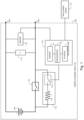
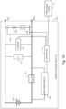
- FIG. 1 shows an example energy storage circuit 106n.
- the energy storage circuit 106n may comprise an energy storage unit 108n, a pre-charge circuit 110n, a first terminal 120n1, and/or a second terminal 120n2.
- the energy storage unit 108n and the pre-charge circuit 110n may be connected in series between the first terminal 120n1 and the second terminal 120n2.
- the energy storage circuit 106n may further comprise a switch Sn, a sensor 112n, and/or a controller 114n.
- the switch Sn may be connected in parallel with the pre-charge circuit 110n.
- the sensor 112n may be connected to the first terminal 120n1, the second terminal 120n2, or to both, and may further be connected to controller 114n.
- the controller 114n may further be connected to pre-charge circuit 110n.
- pre-charge circuit 110n is shown as comprising a switch 116n connected in series with a resistor 118n.
- the switch 116n may be a transistor (e.g., a metal oxide semiconductor field effect transistor (MOSFET), an insulated-gate bipolar transistor (IGBT), or bipolar junction transistor (BJT)) or an electro-mechanical switch.
- MOSFET metal oxide semiconductor field effect transistor
- IGBT insulated-gate bipolar transistor
- BJT bipolar junction transistor
- Figures 1 , 2 , 3 , 4 , 5 , 7 , 6 , 9 , 10 , 11 , 12 , and 13 show the energy storage circuits 106n as comprising an impedance 111n, connected between the first terminal 120n1 and the second terminal 120n2.
- the impedance 111n may represent an equivalent impedance of the energy storage circuit 106n.
- a circuit such as the energy storage circuit 106n may include an actual impedance (e.g., such as a capacitor) connected between the first terminal 120n1 and the second terminal 120n2.
- the sensor 112n may be configured to detect an electrical characteristic of the energy storage circuit 106n.
- the sensor 112n may be a voltage sensor (e.g., implemented by employing a resistive or capacitive divider, a resistive or capacitive bridge, comparators, or other electrical components) configured to measure a voltage between the first terminal 120n1 and the second terminal 120n2 (e.g., the electrical characteristic is a voltage between the first terminal 120n1 and the second terminal 120n2).
- the sensor 112n may be a current sensor as further explained below in conjunction with Figure 9 .
- the sensor 112n may be configured to respond to a negative voltage between the first terminal 120n1 and the second terminal 120n2.
- sensor 112n may be an opto-coupler configured to generate a signal to controller 114n based on a negative voltage between first terminal 120n1 and second terminal 120n2.
- first terminal 120n1 and second terminal 120n2 may relate to a voltage with a polarity which is opposite the polarity of the voltage of the energy storage unit 108n.
- first terminal 120n1 may be connected (e.g., directly or indirectly) to the anode (e.g., the positive terminal) of energy storage unit 108n and the second terminal 120n2 may be connected (e.g., directly or indirectly) to the cathode (e.g., the negative terminal) of energy storage unit 108n.
- the voltage at second terminal 120n2 is higher than the voltage at the first terminal 120n1, then the voltage between the first terminal 120n1 and the second terminal 120n2 may be considered as a negative voltage, with respect to the voltage of energy storage unit 108n.
- the controller 114n may be partially or fully implemented as one or more computing devices and/or may include one or more processors, such as an Application Specific Integrated Circuit (ASIC) controller, a Field Programmable Gate Array (FPGA) controller, a microcontroller, and/or a multipurpose computer.
- the controller 114n may comprise one or more processors 115 connected to a memory 117 and/or one or more Input/Output (I/O) ports 123.
- Th memory 117 may store computer readable instructions as well as data (e.g., measurements from sensor(s) 112n or parameters).
- I/O ports 123 may be configured to connect modules (e.g., sensor(s) 110, pre-charge circuit 110n, or other modules or circuits as may further be elaborated below) to the processor 115.
- the one or more processors 115 may execute the instructions, which may result in the controller 114n performing one or more steps and/or functions as described herein that are attributed to the controller 114n.
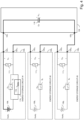
- FIG. 2 shows a system 200 comprising a cascade 102 of energy storage circuits 1061-106N, which may be connected to a second circuit 104 (e.g., a Battery Management System).
- the cascade 102 may be, for example, a part of a storage system constructed from a plurality of energy storage circuits 1061-106N.
- the second circuit 104 may comprise the terminals 1031 and 1032, and a capacitor 119 connected between the terminals 1031 and 1032.
- the second circuit 104 may be configured to provide or generate a pre-charge signal 121 (e.g., via a switch, or a second controller).
- the switch may be a mechanical switch, an electro-mechanical switch, or an electrical switch (e.g., a Metal Oxide Semiconductor Field Effect Transistor - MOSFET, a Bipolar Junction Transistor - BJT, Insulated Gated Bipolar Transistor - IGBT, or the like).
- the first terminal 120n1 of the energy storage circuit 106n may be connected to the second terminal 120(n-1)2 of the energy storage circuit 106n-1.
- the first terminal 12011 of the energy storage circuit 1061 may be connected to the terminal 1031 of the second circuit 104, and/or the second terminal 120N2 of the energy storage circuit 106 may be connected to the terminal 1032 of the second circuit 104. According to the disclosure herein, it may be required to pre-charge the capacitor 119. It may also be required to pre-charge the energy storage circuits. According to the disclosure herein, one of the controllers 1141-114N may receive a signal, such as the pre-charge signal 121 (e.g., a signal generated by a switch in energy storage circuit 106n, the second circuit 104, or a controller in second circuit 104).
- the pre-charge signal 121 e.g., a signal generated by a switch in energy storage circuit 106n, the second circuit 104, or a controller in second circuit 104.
- one or more of controllers 1141-114n of the energy storage circuits 1061-106N may close the corresponding pre-charge circuit 1101-110n. However, the controllers 1141-114n may not receive pre-charge signal 121 at the same time. In some cases, the controllers 1141-114n or the pre-charge circuits 1101-110n may not respond concurrently. In some examples, some of the controllers 1141-114n may not receive the pre-charge signal 121 at all (e.g., due to disconnected communications, or signal disruption).
- the controller 1141 may receive a pre-charge signal 121 and close the pre-charge circuit 1101 (e.g., the controlled pre-charge circuit 1101 may close the switch 1161, thereby creating a current path between the second terminal 12012 and the negative terminal 12011 of energy storage circuit 1061). Closing the pre-charge circuit 1101 may result in an equivalent circuit shown in Figure 4.
- Figure 4 shows an example equivalent circuit where the cascade 102 may comprise three energy storage circuits 1061, 1062, and 1063, and the pre-charge circuit 1101 may be closed. It is noted that, for the sake of clarity of the figure, not all the components of energy storage circuits 1061, 1062, and 1063 are shown in Figure 4 . Also, components shown with a dashed line indicate that these components do not form a part of the equivalent circuit, but are shown for the sake of the explanations herein.
- the voltage across equivalent impedances 1111, 1112 and 1113, and across capacitor 119 may be zero, and the voltage across each of switches S1, S2, or S3 may be the voltage, Vunitn, of the corresponding energy storage units 1081, 1082, or 1083.
- Figures 5A, 5B, and 5C may show voltages across the impedances and the switches of the energy storage circuits 1061, 1062, and 1063 of Figure 4 , respectively.
- the voltages, VZ1, VZ2, and VZ3 across impedances 1111, 1112 and 1113 are zero, and the voltages VS1, VS2, and VS3 across each switches S1, S2, or S3 may correspond to Vunit1, Vunit2, and Vunit3, respectively.
- the capacitor 119 may start charging.
- the voltage, VS1, across the switch S1 may reduce, and the voltage, Vz1, across the impedance 1111 may rise.
- the rise of Vz1 may result in a positive voltage across the first terminal 12011 and the second terminal 12012 (e.g., the voltage at first terminal 12011 may be higher than the voltage at second terminal 12012).
- the capacitor 119 and the equivalent impedances 1112 and 1113 may form an impedance divider, which divides the voltage, VZ1 (e.g., the voltage over impedance 1111) based on the values of these impedances.
- This impedance divider may produce a voltage VCc between the terminal 1031 and the terminal 1032, a voltage VZ2 between the terminal 12021 and the terminal 12022, and a voltage VZ3 between the terminal 12031 and the terminal 12032.
- the voltage, VZ2, between the terminal 12021 and the terminal 12022 may reduce, such that the polarity of VZ2 may be opposite the polarity of energy storage unit 1082 (e.g., the voltage between terminal 12021 and terminal 12022 becomes negative).
- the voltage, Vs2, across the switch S2 may start to rise above the voltage level, Vunit2, of the energy storage unit 1082.
- the voltage, VZ3, between the terminal 12031 and the terminal 12032 may reduce, such that the polarity of VZ3 may be opposite the polarity of the energy storage unit 1083 (e.g., the voltage between the terminal 12031 and the terminal 12032 becomes negative).
- the voltage, Vs3, over switch S3 may start to rise above the corresponding voltage, Vunit3, of the energy storage unit 1083.
- the controller 1142 may be configured to, based on measurements by the sensor 1122 detect that the voltage between the terminal 12021 and the terminal 12022 is negative (e.g., below a threshold voltage Vth2), and close the pre-charge circuit 1102.
- the controller 1143 may be configured to, based on measurements by the sensor 1123, detect that the voltage between the terminal 12031 and the terminal 12032 is negative (e.g., below a threshold voltage Vth3 which may be different from Vth2), and close the pre-charge circuit 1103.
- the controllers 1142 and 1143 and/or the pre-charge circuits 1102 and 1103, may not respond concurrently to a signal.
- the pre-charge circuit 1103 may close prior to the pre-charge circuit 1102.
- the controller 1143 may control the pre-charge circuit 1103 to close, based on measurements from the sensor 1123. For example, the controller 1143 may detecting that the voltage, VZ3, between the terminal 12031 and the terminal 12032 is negative (e.g., below a threshold Vth3).
- Figure 7 shows an example of an equivalent circuit where the cascade 102 may comprise three energy storage circuits 1061, 1062, and 1063, and all the pre-charge circuits 1101, 1102, and 1103 may be closed.
- the controller 1142 may be configured to, based on measurements from the sensor 1122, detect that the voltage between the terminal 12021 and the terminal 12022 is negative (e.g., below a threshold Vth2) and control the pre-charge circuit 1102 to close a current path between the terminal 12022 and the energy storage unit 1082.
- the ratings of the switches S1-SN may be determined to be above the corresponding Vunitn, by a determined value (e.g., related to a voltage detection threshold Vthn), regardless of the number of energy storage circuits 1061-106N connected in cascade 102.
- a single one of the controllers 1141-114N may receive the pre-charge signal 121, and close the corresponding pre-charge circuit 110n thereof, and the rest of the controllers may control the corresponding pre-charge circuits 1101-110N to close as well, based on a negative voltage between the corresponding the first terminal 120n1 and the second terminal 120n2.
- the circuit 104 may control each of switches S1-SN to start conducting based on a determination (e.g., by a user, by circuit 104, by a signal) that power should be produced (e.g., discharged) from cascade 102 of energy storage circuits 1061-106N, or based on a determination that cascade 102 of energy storage circuits 1061-106N should be charged.
- a determination e.g., by a user, by circuit 104, by a signal
- power should be produced e.g., discharged
- Figure 8 shows an energy storage circuit 106n comprising an impedance 113n connected in parallel to the switch Sn (e.g., also connected between the terminal 120n2 and the negative terminal of the energy storage unit 108n).
- the impedance 113n may comprise a capacitor and a resistor.
- the impedance 113n may be an actual impedance, or represent the parasitic capacitance and resistance of the switch Sn. In both cases (e.g., the impedance 113n, the impedance of the energy storage unit 108, or both) may be represented by an equivalent impedance 111n.
- the impedance 111n may comprise an actual capacitor connected between the terminal 120n1 and the terminal 120n2.
- the disclosure herein relates to the impedance 111n for the ease and clarity of the description of the embodiments. Nevertheless, this should not be considered as limiting.
- the senor 112n may be an opto-coupler configured to generate a signal to the controller 114n based on detecting a negative voltage between the first terminal 120n1 and the second terminal 120n2.
- the opto-coupler is connected such that the transmitter Light Emitting Diode (LED) may be forward-biased in case the voltage between the first terminal 120n1 and the second terminal 120n2 is negative (e.g., the voltage at second terminal 120n2 is higher than the voltage at first terminal 120n1).
- the receiver photosensor of the opto-coupler may be connected to the controller 114n and provide a signal to the controller 114n in case the voltage between first terminal 120n1 and the second terminal 120n2 is negative.
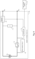
- Figure 9 shows an energy storage circuit 106n in which the sensor 112n is a current sensor.
- a current sensor may be implemented by employing a Current Transformer (CT) sensor, a Hall Effect sensor, or a zero-flux sensor.
- CT Current Transformer
- the sensor 112n may be configured to measure a current through the first terminal 120n1 or through the second terminal 120n2 (e.g., the electrical characteristic is a current through the first terminal 120n1 or the second terminal 120n2). For example, in case of a negative voltage is detected between the terminal 120n1 and the terminal 120n2, a current may flow from the terminal 120n2 to the terminal 120n1.
- the sensor 112n may detect such a current and provide an indication to the controller 114n.
- the pre-charge circuit 110n and the switch Sn may be connected between the terminal 120n2 and the negative terminal of the energy storage unit 108n.
- the pre-charge circuit 110n and the switch Sn may be connected between the terminal 120n1 and the positive terminal of energy storage unit 108n.
- the pre-charge circuit 110n may be connected between the terminal 120n1 and the positive terminal of energy storage unit 108n, and the switch Sn may be connected between the terminal 120n2 and the negative terminal of the energy storage unit 108n.
- the pre-charge circuit 110n may be connected between the terminal 120n2 and the negative terminal of energy storage unit 108n, and the switch Sn may be connected between the terminal 120n1 and the positive terminal of the energy storage unit 108n.
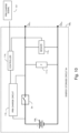
- the plurality of energy storage circuits 1061-106N Prior to closing the pre-charge circuits 1101-110N, the plurality of energy storage circuits 1061-106N (e.g., as may be shown in Figures 1B or 1C) may be required to connect to each other. In some cases, it may be required to connect a plurality of energy storage circuits 1061-106N when the voltage between terminals 120n1 and 120n2 may be low (e.g., less than 10V, less than 1V), or even zero. To that end, and with reference to Figure 11 , the energy storage circuit 106n may comprise the circuitry 124n connected between the terminal 120n1 and the terminal 120n2.
- the controller 114n may be connected to the circuitry 124n and the controller 114n may control the circuitry 124n to reduce the voltage between the terminal 120n1 and the terminal 120n2.
- the circuitry 124n may comprise a series connection of a resistor 126n and a switch 128n.
- the controller 114n may control the switch 128n to close a conduction path between the terminal 120n1 and the terminal 120n2, thereby reducing the voltage between the terminal 120n1 and the terminal 120n2.
- the switch 116n may be implemented by a semiconductor switch (e.g., a Metal Oxide Semiconductor Field Effect Transistor - MOSFET, a Bipolar Junction Transistor - BJT, Insulated Gated Bipolar Transistor - IGBT, or the like).
- a semiconductor switch e.g., a Metal Oxide Semiconductor Field Effect Transistor - MOSFET, a Bipolar Junction Transistor - BJT, Insulated Gated Bipolar Transistor - IGBT, or the like.
- An anode of the body diode 130n of the switch 116n may be connected to the terminal 120n2 and the cathode of the body diode 130n of switch 116n may be connected to the negative terminal of the energy storage unit 108n.
- the cathode of the body diode 130n may be connected to the terminal 120n2 and the anode of the body diode 130n may be connected to the negative terminal of energy storage unit 108n.
- the switch 128n may be implemented by a semiconductor switch. An anode of the body diode 131n of the switch 128n may be connected to the terminal 120n1 and the cathode of the body diode 131n of the switch 128n may be connected to the terminal 120n2.
- the switch Sn is shown as a series connection of two semiconductor switches 130n and 132n, with opposing body diodes 133n and 135n.
- the controller 114n may control the switch 130n to switch to an on stage when the energy storage unit 108n needs to be discharged. Additionally, the controller 114n may control the switch 132n to switch to an on state when the energy storage unit 108n needs to be charged.
- a controller may control a switch (e.g., switch 128n) to reduce a voltage between a first terminal (e.g., terminal 120n1) and a second terminal (e.g., terminal 120n2) of an energy storage circuit (e.g., energy storage circuit 106n).
- a switch e.g., switch 128n
- an energy storage circuit e.g., energy storage circuit 106n
- the energy storage circuit may be connected to other circuits.
- the energy storage circuits 1061-106N may be connected in series and to the second circuit 104, as shown in Figures 2 and 3 .
- a sensor may detect a polarity of a voltage between the first terminal and the second terminal.
- the sensor may be a voltage sensor, a current sensor, or may be configured to respond (e.g., an opto-coupler) to a negative voltage between the first terminal and the second terminal.
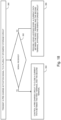
- the controller may determine if the polarity of the voltage between the first terminal and the second terminal is opposite of the polarity of the energy storage unit. Based on the determination that the polarity of the voltage between the first terminal and the second terminal is opposite the polarity of the energy storage, the method may proceed to step 210. Based on the determination that the polarity of the voltage between the first terminal and the second terminal is not opposite the polarity of the energy storage, the method may proceed to step 208.
- step 208 the controller may determine if a pre-charge activation signal was received. In case a pre-charge activation signal was received, the method may proceed to step 210. In case a pre-charge activation signal was not received, the method may return to step 204. It is noted that the order of steps 206 and 208 may be interchangeable.
- the controller may control a pre-charge circuit (e.g., pre-charge circuit 110n) to close a current path between the first terminal and the second terminal.
- a pre-charge circuit e.g., pre-charge circuit 110n
- the controller may control (e.g., turn on) a production switch (e.g., switch Sn) to conduct, in response a signal.
- a production switch e.g., switch Sn
- the circuit 104 may provide a signal to controller 114n to control switch Sn to an on state.
- controller 114n may control pre-charge circuit 110n to close a current path between the first terminal and the second terminal.
- controller 114n may control pre-charge circuit 110n to open a current path between the first terminal and the second terminal based on another signal received from circuit 104, or based on a measurement from sensor 112n (e.g., indicating that the voltage between the terminals in positive).
- Controller 114n may control pre-charge circuit 110n to open a current path between the first terminal and the second terminal based on an elapsed time period (e.g., from the time controller 114 closed the current path).
- controllers 1141-114N may be implemented as a single controller device, connected to each of pre-charge circuits 1101-110N and configured to activate the pre-charge circuits 1101-110N (e.g., responsive to receiving pre-charge signal 121 or responsive to receiving measurements from sensors 1121-112N).
- FIG. 15 shows an energy storage circuit 106n that may comprise a bypass diode 140n connected in parallel to a series connection of the energy storage unit 108n and the pre-charge circuit 1 10n.
- the anode of bypass diode 140n may be connected to the terminal 120n2 and the cathode of bypass diode 140n may be connected to the terminal 120n1.
- the sensor 112n may be optional.
- the bypass diode 140n may provide a current path (e.g., diode 140n is forward biased and becomes conductive) between the first terminal 120n1 and the second terminal 120n2, and this current path may bypass the energy storage circuit 106n.
- FIGS 16A , 16B , and 16C show alternative embodiments of the system in Figure 3 .
- the cascade 102 may comprise three energy storage circuits 1061, 1062, and 1063. It is noted that, for the sake of clarity of the figure, not all the components of energy storage circuits 1061, 1062, and 1063 are shown in Figures 16A , 16B , and 16C . Also, components shown with a dashed line indicate that these components do not form a part of the equivalent circuit, but are shown for the sake of the explanations herein. Reference is also made to Figures 17A, 17B, and 17C which may show voltages across the impedances and the switches of the energy storage circuits 1061, 1062, and 1063 of Figures 16A , 16B , and16C, respectively.
- the voltages, VZ1, VZ2, and VZ3 across the impedances 1111, 1112 and 1113, respectively, are zero (e.g., since the capacitor 119 is discharged), and the voltages VS1, VS2, and VS3 across each switches S1, S2, or S3 may correspond to Vunit1, Vunit2, and Vunit3, respectively.
- the capacitor 119 may start charging.
- the voltage, VS1, across the switch S1 may reduce, and the voltage, Vz1, across the impedance 1111 may rise.
- the rise of Vz1 may result in a positive voltage across the first terminal 12011 and the second terminal 12012 (e.g., the voltage at first terminal 12011 may be higher than the voltage at second terminal 12012).
- the capacitor 119 and the equivalent impedances 1112 and 1113 may form an impedance divider, which divides the voltage, VZ1 (e.g., the voltage over impedance 1111) based on the values of these impedances.
- This impedance divider may produce a voltage VCc between the terminal 1031 and the terminal 1032, a voltage VZ2 between the terminal 12021 and the terminal 12022, and a voltage VZ3 between the terminal 12031 and the terminal 12032.
- the voltage, VZ2, between the terminal 12021 and the terminal 12022 may reduce, such that the polarity of VZ2 may be opposite the polarity of energy storage unit 1082 (e.g., the voltage between terminal 12021 and terminal 12022 becomes negative) to a level at which the bypass diode 1402 conducts (e.g., bypass diode 1402 becomes forward biased).
- the bypass diode 1402 may provide a current path between terminal 12021 and terminal 12022 and this current path may bypass the energy storage circuit 1062.
- the voltage, Vs2, across the switch S2 may rise above the voltage of Vunit2 by the voltage drop across bypass diode 1402.
- the voltage, VZ3, between the terminal 12031 and the terminal 12032 may reduce, such that the polarity of VZ3 may be opposite the polarity of the energy storage unit 1083 (e.g., the voltage between the terminal 12031 and the terminal 12032 becomes negative) to a level at which bypass diode 1403 may conduct (e.g., bypass diode 1403 becomes forward biased) and provide a current path between the terminal 12031 and the terminal 12032, and this current path may bypass the energy storage circuit 1063.
- the voltage, Vs3, across the switch S3 may rise above the voltage of Vunit3 by the voltage drop across bypass diode 1403.
- the controllers 1142 and 1143 and/or the pre-charge circuits 1102 and 1103, do not respond concurrently to a signal.
- the voltage, Vs2, across the switch S2 may remain at the level of the voltage of the energy storage unit 1082 until the controller 1142 responds to the pre-charge activation signal. Thereafter, the voltage Vs2 reduces and the voltage Vz2 may increase.
- the voltage, Vs3, across the switch S3 remains at the level of the voltage of the energy storage unit 1083 until the controller 1143 responds to the pre-charge activation signal. Thereafter, the voltage Vs3 may reduce and the voltage Vz3 may increase.
- switches S1, S2, and S3 need not be rated to operate at a voltage above level of the voltage of energy storage unit 108n.
- a pre-charge activation signal is transmitted to a plurality of energy storage circuits such as the energy storage circuits1061-106N.
- the circuit 104 ( Figure 3 ) may be configured to provide or generate a pre-charge signal 121 (e.g., via a switch, or a second controller).
- step 302 a determination is made, by each of controllers 1141-114N of plurality of energy storage circuits 1061-106N, if the pre-charge activation signal, such as pre-charge signal 121, was received.
- step 304 responsive to receiving the pre-charge activation signal 121, one or more of controllers 1141-114n of the energy storage circuits 1061-106N may close the corresponding pre-charge circuit 1101-110n thereby creating a current path between the terminal 1202 and the terminal 1201 of energy storage circuit 106.
- a current path may be provided by using bypass diode 104n, and this current path may bypass the energy storage circuits 1061-106N that did not receive the pre-charge activation signal. It is noted that the energy storage circuit 106n may not receive the pre-charge activation signal in case of a failure in communications. The energy storage circuit 106n may not receive the pre-charge activation signal in case in case the controller 114n have a slower response time to the pre-charge activation signal than controllers 114n of other energy storage circuits 106n.
- Examples of algorithms, functions, processes and control of circuits, and systems described herein may be embodied in hardware control logic and memory (e.g., application specific integrated circuits, field programmable gate arrays) and/or computer-executable instructions executed by one or more computers or other devices (e.g., controllers 114n).
- the computers and other devices that execute the instructions may include microprocessors, microcontrollers, digital signal processors, embedded controllers, etc.
- Computer-executable instructions may include routines, programs, objects, components, data structures, etc. that perform particular tasks or implement particular abstract data types when executed by a processor in a computer or other device.
- the computer executable instructions may be stored on a computer readable medium such as a hard disk, optical disk, removable storage media, solid state memory, RAM, etc.
- a power converter, system or device may comprise one or more processors and memory storing computer executable instructions, that when executed by the one or more processors, performs the steps of Figures 14 and/or 18, or any other control function described herein.
Landscapes
- Engineering & Computer Science (AREA)
- Power Engineering (AREA)
- Charge And Discharge Circuits For Batteries Or The Like (AREA)
Applications Claiming Priority (1)
| Application Number | Priority Date | Filing Date | Title |
|---|---|---|---|
| US202363479625P | 2023-01-12 | 2023-01-12 |
Publications (2)
| Publication Number | Publication Date |
|---|---|
| EP4401276A2 true EP4401276A2 (de) | 2024-07-17 |
| EP4401276A3 EP4401276A3 (de) | 2024-08-07 |
Family
ID=89619205
Family Applications (1)
| Application Number | Title | Priority Date | Filing Date |
|---|---|---|---|
| EP24151593.1A Pending EP4401276A3 (de) | 2023-01-12 | 2024-01-12 | Vorladen und verbinden eines energiespeichersystems |
Country Status (3)
| Country | Link |
|---|---|
| US (1) | US20240243590A1 (de) |
| EP (1) | EP4401276A3 (de) |
| JP (1) | JP2024099504A (de) |
Families Citing this family (2)
| Publication number | Priority date | Publication date | Assignee | Title |
|---|---|---|---|---|
| US12136840B2 (en) * | 2021-12-24 | 2024-11-05 | Motorola Solutions, Inc. | Device, battery and system to control battery power |
| US12549007B2 (en) * | 2024-05-22 | 2026-02-10 | Caterpillar Inc. | Systems and methods of load pre-charging |
Family Cites Families (2)
| Publication number | Priority date | Publication date | Assignee | Title |
|---|---|---|---|---|
| CN109677296B (zh) * | 2018-12-26 | 2022-08-05 | 法法汽车(中国)有限公司 | 一种动力电池及其控制方法、电动汽车 |
| US12401207B2 (en) * | 2020-12-10 | 2025-08-26 | B2U Storage Solutions Inc. | Energy storage system and method employing second-life electric vehicle batteries |
-
2024
- 2024-01-09 US US18/407,599 patent/US20240243590A1/en active Pending
- 2024-01-12 EP EP24151593.1A patent/EP4401276A3/de active Pending
- 2024-01-12 JP JP2024003091A patent/JP2024099504A/ja active Pending
Also Published As
| Publication number | Publication date |
|---|---|
| EP4401276A3 (de) | 2024-08-07 |
| JP2024099504A (ja) | 2024-07-25 |
| US20240243590A1 (en) | 2024-07-18 |
Similar Documents
| Publication | Publication Date | Title |
|---|---|---|
| EP4401276A2 (de) | Vorladen und verbinden eines energiespeichersystems | |
| US20230266395A1 (en) | Voltage detecting circuit, abnormality detector, and battery system | |
| US8269469B2 (en) | Equalizing method and circuit for ultracapacitors | |
| US6437539B2 (en) | Method and device for balancing charges of a plurality of series-connected battery cells | |
| US10468972B2 (en) | Power converter including a plurality of converter cells connected in multiple series | |
| EP3091658B1 (de) | Solarzellenprüfvorrichtung und solarzellenprüfverfahren | |
| CN114128078A (zh) | 一种终端设备的供电系统、方法、芯片及终端设备 | |
| CN102832651A (zh) | 用于电池包的电池管理系统及方法 | |
| US7443155B2 (en) | Voltage detecting apparatus | |
| CN106645893B (zh) | 电荷泵的输出电压检测电路和电荷泵 | |
| US20170005487A1 (en) | Method of forming a balancing circuit for a plurality of battery cells and structure therefor | |
| CN105510759B (zh) | 漏电检测设备及其检测方法 | |
| US9455580B2 (en) | Battery management system and method | |
| KR20200058995A (ko) | 배터리 관리 장치 및 그것을 포함하는 배터리팩과 전원 시스템 | |
| KR102336746B1 (ko) | 신재생 에너지원의 전력 제어 회로 | |
| CN103151815B (zh) | 一种电池组单元电池均衡充电控制方法 | |
| CN115021379A (zh) | 一种充电电路和电子设备 | |
| WO2017185671A1 (zh) | 一种电压采集电路及电路控制方法 | |
| CN108008312A (zh) | 蓄电池组状态在线测量电路及方法 | |
| KR20210025284A (ko) | 에너지 하베스터용 부하 연결 장치 | |
| US10224919B2 (en) | Power switch control by supply voltage terminal | |
| CN109904900B (zh) | 电池控制电路、电池控制装置以及电池包 | |
| US20120182022A1 (en) | Method of indicating voltage, voltage indicating apparatus, and battery pack | |
| CN111162587B (zh) | 一种用于可充电电池的电子装置 | |
| CN106169784B (zh) | 恒流充电装置 |
Legal Events
| Date | Code | Title | Description |
|---|---|---|---|
| PUAI | Public reference made under article 153(3) epc to a published international application that has entered the european phase |
Free format text: ORIGINAL CODE: 0009012 |
|
| STAA | Information on the status of an ep patent application or granted ep patent |
Free format text: STATUS: THE APPLICATION HAS BEEN PUBLISHED |
|
| PUAL | Search report despatched |
Free format text: ORIGINAL CODE: 0009013 |
|
| AK | Designated contracting states |
Kind code of ref document: A2 Designated state(s): AL AT BE BG CH CY CZ DE DK EE ES FI FR GB GR HR HU IE IS IT LI LT LU LV MC ME MK MT NL NO PL PT RO RS SE SI SK SM TR |
|
| AK | Designated contracting states |
Kind code of ref document: A3 Designated state(s): AL AT BE BG CH CY CZ DE DK EE ES FI FR GB GR HR HU IE IS IT LI LT LU LV MC ME MK MT NL NO PL PT RO RS SE SI SK SM TR |
|
| RIC1 | Information provided on ipc code assigned before grant |
Ipc: H02J 7/34 20060101ALI20240701BHEP Ipc: H02J 7/00 20060101AFI20240701BHEP |
|
| P01 | Opt-out of the competence of the unified patent court (upc) registered |
Free format text: CASE NUMBER: APP_42481/2024 Effective date: 20240718 |
|
| STAA | Information on the status of an ep patent application or granted ep patent |
Free format text: STATUS: REQUEST FOR EXAMINATION WAS MADE |
|
| 17P | Request for examination filed |
Effective date: 20250205 |