EP4401273A1 - Security system for a vehicle, vehicle comprising such a security system and associated supervision method - Google Patents
Security system for a vehicle, vehicle comprising such a security system and associated supervision method Download PDFInfo
- Publication number
- EP4401273A1 EP4401273A1 EP23150890.4A EP23150890A EP4401273A1 EP 4401273 A1 EP4401273 A1 EP 4401273A1 EP 23150890 A EP23150890 A EP 23150890A EP 4401273 A1 EP4401273 A1 EP 4401273A1
- Authority
- EP
- European Patent Office
- Prior art keywords
- control unit
- safety
- vehicle
- switch
- input line
- Prior art date
- Legal status (The legal status is an assumption and is not a legal conclusion. Google has not performed a legal analysis and makes no representation as to the accuracy of the status listed.)
- Granted
Links
Images


Classifications
-
- B—PERFORMING OPERATIONS; TRANSPORTING
- B60—VEHICLES IN GENERAL
- B60L—PROPULSION OF ELECTRICALLY-PROPELLED VEHICLES; SUPPLYING ELECTRIC POWER FOR AUXILIARY EQUIPMENT OF ELECTRICALLY-PROPELLED VEHICLES; ELECTRODYNAMIC BRAKE SYSTEMS FOR VEHICLES IN GENERAL; MAGNETIC SUSPENSION OR LEVITATION FOR VEHICLES; MONITORING OPERATING VARIABLES OF ELECTRICALLY-PROPELLED VEHICLES; ELECTRIC SAFETY DEVICES FOR ELECTRICALLY-PROPELLED VEHICLES
- B60L3/00—Electric devices on electrically-propelled vehicles for safety purposes; Monitoring operating variables, e.g. speed, deceleration or energy consumption
- B60L3/04—Cutting off the power supply under fault conditions
-
- B—PERFORMING OPERATIONS; TRANSPORTING
- B60—VEHICLES IN GENERAL
- B60R—VEHICLES, VEHICLE FITTINGS, OR VEHICLE PARTS, NOT OTHERWISE PROVIDED FOR
- B60R16/00—Electric or fluid circuits specially adapted for vehicles and not otherwise provided for; Arrangement of elements of electric or fluid circuits specially adapted for vehicles and not otherwise provided for
- B60R16/02—Electric or fluid circuits specially adapted for vehicles and not otherwise provided for; Arrangement of elements of electric or fluid circuits specially adapted for vehicles and not otherwise provided for electric constitutive elements
- B60R16/03—Electric or fluid circuits specially adapted for vehicles and not otherwise provided for; Arrangement of elements of electric or fluid circuits specially adapted for vehicles and not otherwise provided for electric constitutive elements for supply of electrical power to vehicle subsystems or for
-
- H—ELECTRICITY
- H02—GENERATION; CONVERSION OR DISTRIBUTION OF ELECTRIC POWER
- H02J—ELECTRIC POWER NETWORKS; CIRCUIT ARRANGEMENTS OR SYSTEMS FOR SUPPLYING OR DISTRIBUTING ELECTRIC POWER; SYSTEMS FOR STORING ELECTRIC ENERGY
- H02J7/00—Circuit arrangements for charging or discharging batteries or for supplying loads from batteries
- H02J7/60—Circuit arrangements for charging or discharging batteries or for supplying loads from batteries including safety or protection arrangements
- H02J7/663—Circuit arrangements for charging or discharging batteries or for supplying loads from batteries including safety or protection arrangements using battery or load disconnect circuits
-
- B—PERFORMING OPERATIONS; TRANSPORTING
- B60—VEHICLES IN GENERAL
- B60R—VEHICLES, VEHICLE FITTINGS, OR VEHICLE PARTS, NOT OTHERWISE PROVIDED FOR
- B60R16/00—Electric or fluid circuits specially adapted for vehicles and not otherwise provided for; Arrangement of elements of electric or fluid circuits specially adapted for vehicles and not otherwise provided for
- B60R16/02—Electric or fluid circuits specially adapted for vehicles and not otherwise provided for; Arrangement of elements of electric or fluid circuits specially adapted for vehicles and not otherwise provided for electric constitutive elements
- B60R16/023—Electric or fluid circuits specially adapted for vehicles and not otherwise provided for; Arrangement of elements of electric or fluid circuits specially adapted for vehicles and not otherwise provided for electric constitutive elements for transmission of signals between vehicle parts or subsystems
- B60R16/0231—Circuits relating to the driving or the functioning of the vehicle
- B60R16/0232—Circuits relating to the driving or the functioning of the vehicle for measuring vehicle parameters and indicating critical, abnormal or dangerous conditions
-
- B—PERFORMING OPERATIONS; TRANSPORTING
- B60—VEHICLES IN GENERAL
- B60R—VEHICLES, VEHICLE FITTINGS, OR VEHICLE PARTS, NOT OTHERWISE PROVIDED FOR
- B60R25/00—Fittings or systems for preventing or indicating unauthorised use or theft of vehicles
- B60R25/10—Fittings or systems for preventing or indicating unauthorised use or theft of vehicles actuating a signalling device
- B60R25/1018—Alarm systems characterised by features related to the general power supply
-
- B—PERFORMING OPERATIONS; TRANSPORTING
- B60—VEHICLES IN GENERAL
- B60R—VEHICLES, VEHICLE FITTINGS, OR VEHICLE PARTS, NOT OTHERWISE PROVIDED FOR
- B60R25/00—Fittings or systems for preventing or indicating unauthorised use or theft of vehicles
- B60R25/20—Means to switch the anti-theft system on or off
-
- H—ELECTRICITY
- H01—ELECTRIC ELEMENTS
- H01H—ELECTRIC SWITCHES; RELAYS; SELECTORS; EMERGENCY PROTECTIVE DEVICES
- H01H9/00—Details of switching devices, not covered by groups H01H1/00 - H01H7/00
- H01H9/16—Indicators for switching condition, e.g. "on" or "off"
- H01H9/167—Circuits for remote indication
Definitions
- the disclosure relates generally to the safety of vehicles for road transportation of dangerous goods.
- the disclosure relates to a security system for a vehicle and to a vehicle comprising such a safety circuit.
- the disclosure also relates to a supervision method for a vehicle.
- the disclosure can be applied in heavy-duty vehicles, such as trucks, buses, and construction equipment.
- ADR regulations concerns the road transportation of hazardous goods.
- ADR is an acronym for the expression - originally in French - "Agreement concerning the International Carriage of Dangerous Goods by Road”.
- the aim of ADR regulations is to ensure the safety of the driver and operators when the hazardous material are being loaded or unloaded or hazardous operation are done near the truck.
- a vehicle - usually a truck - carrying hazardous materials must be equipped with a safety switch, which must be triggered by the driver or by an operator around the vehicle, for any activity involving hazardous materials, such as loading/unloading of hazardous material, presence of explosives materials, etc.
- ADR regulations states that as soon as the safety switch is triggered, any electric equipment or accessory of the vehicle, more generally any electric load of the vehicle, shall be cut off from its electric power supply within 200 milliseconds.
- a truck comprises additional power sources such as, for example, a solar panel, an additional battery or a capacitor, such additional power source might continue to provide electric power to an accessory, for example in case of defect or wrong usage, which could lead to dangerous, potentially life threatening, situations.
- the invention aims at providing a security system circuit for a vehicle, which provides improved safety.
- the invention relates to a security system circuit for a vehicle, the security system comprising an electronic main control unit, and at least one electronically operated switch, which is arranged on an input line of an electric load of the vehicle, each electronically operated switch being controlled by the main control unit and being is configured to switch between a connected configuration, where said electronically operated switch allows electricity to flow through the input line between a main electric power source of the vehicle and the electric load, and a cutoff configuration, where said electronically operated switch prevents electricity from circulating through the input line between the main power source and said electric load.
- the security system also comprises a safety switch, configured to be activated by a user of the vehicle, the safety switch being configured to control the main control unit, so that each electronically operated switch switches to its cutoff configuration when the safety switch is activated.
- the security system further comprises an electronic safety control unit, which is different from the main control unit, the safety control unit being powered by the main power source, at least one current sensor, each current sensor being is configured to detect electric current flowing through a respective input line of said electric load, and alarm means, configured to alert a user of the vehicle.
- the safety control unit is configured to change from a waiting mode to an active mode under the control of a main control unit of the vehicle, which is different from the safety control unit, the safety control unit changing to the active mode when the safety switch is activated, and to activate the alarm means when the safety control unit is in the active mode, and after a predetermined first time interval from the moment the safety switch is activated, at least one current sensor detects electric current flowing through the corresponding input line.
- a technical benefit may include alerting the user(s) in and/or around the vehicle in case of the electric load still uses electric power despite the safety switch being triggered. The safety of the truck is therefore improved.
- the safety control unit after the safety control unit activates the alarm means, the safety control unit turns off the alarm means after a predetermined second time interval.
- a technical benefit may include alerting the user of a potential malfunction of the main control unit without startling the user.
- the second time interval ends 200 ms after the safety switch is activated.
- a technical benefit may include fulfilling ADR regulation for the safety system itself.
- first time interval is equal to 50 ms after the safety switch is activated.
- a technical benefit may include allowing the transient electrical phenomenon occurring after the opening of each electronically operated switch, to end, in order to avoid false alarms.
- the electronically operated switchs include an additional electronically operated switch, whereas the power supply of the safety control unit is controlled by the main control unit through the additional electronically operated switch, and whereas the main control unit is configured to switch said additional electronically operated switch in its cutoff configuration after a predetermined time interval after the safety switch is activated.
- a technical benefit may include improving the overall safety by including the safety control unit in its own supervision.
- a second aspect of the disclosure concerns a road vehicle, in particular a truck, comprising the security system as previously described, a main power source, for example a battery, and one electric load with at a first input line, which is connected to the main power source, whereas the at least one current sensor include a first sensor, which is arranged on the first input line.
- a main power source for example a battery
- the at least one current sensor include a first sensor, which is arranged on the first input line.
- a technical benefit may include having a vehicle with improved safety when handling dangerous goods.
- the road vehicle comprises an additional power source, for example a capacitor or a solar panel, the additional power source being different from the main power source, the electric load comprises a second input line, which is different from the first input line and which is connected to the additional power source, whereas the at least one current sensor include a second sensor, which is arranged on the second input line.
- a technical benefit may include improving the safety of road vehicles comprising additional power sources.
- a third aspect of the disclosure concerns a supervision method to supervise electric accessories of a vehicle comprising the safety control unit according to any one of previous claims, the supervision method comprising the following steps:
- a technical benefit may include the same advantages as those mentioned above for the security system of the invention.
- the supervision method comprises the following additional steps: after activating the alarm means are activated, turning off alarm means after a predetermined second time interval.
- a technical benefit may include alerting the user of a potential malfunction of the main control unit without startling the user.
- the second time interval ends 200 ms after the safety switch is activated.
- a technical benefit may include ensuring that the alarm means themselves fulfill ADR regulations.
- the first time interval is equal to 50 ms.
- a technical benefit may include allowing the transient electrical phenomenon occurring after the opening of each electronically operated switch, to end, in order to avoid false alarms.
- FIG. 1 is an exemplary vehicle 10 according to an embodiment of the invention.
- the vehicle 10 is a road vehicle and is configured to carry goods that fall under the ADR definition, in other words dangerous goods.
- the vehicle 10 is represented by a cistern truck and comprises a cistern 12, which is arranged on top of a chassis 14.
- the type of vehicle 10 may vary, depending on the type of dangerous goods to be transported.
- the vehicle 10 also comprises a cabin 16 for a driver of the vehicle 10.
- the vehicle 10 comprises a security system 100, which is represented schematically on figure 2 .
- the security system 100 comprises at least one safety switch 102.
- Each safety switch 102 is configured to be activated by a user of the vehicle 10 when needed.
- the vehicle 10 comprises two safety switches 102, with a first safety switch 102 arranged inside the cabin 16, here on a dashboard 18, and a second safety switch 102 arranged outside the cabin 16.
- the second safety switch 20 is arranged on the chassis 20 at a rear end of the vehicle 10.
- the safety switches 102 are represented by pushbuttons. The number, location and shape of the safety switches 102 are not limitative.
- the vehicle 10 comprises a main power source 104, for example a battery such as an acid-lead battery.
- the main power source 104 is configured to store electric power, and to release, when needed, electric power.
- the vehicle 10 also comprises a secondary power source 106, which is different from the main power source 104.
- the secondary power source 106 is a lithium-ion battery, which is configured to harvest electric energy generated while braking, or a solar panel, etc.
- the vehicle 10 also comprises an electric load 110.
- the electric load 110 is a pump, a compressor, a cooling system, etc. More generally, the electric load 110 is a piece of equipment that is powered by electricity.
- the electric load 110 comprises a first input line 114, which is connected to the main power source 104.
- the first input line 114 is represented by a line on figure 2 , with an arrow illustrating the flow of electric power, from the main power source 104 to the electric load 110.
- the electric load 110 also comprises a second input line 116, which is different from the first input line 114 and which is connected to the secondary power source 106.
- the security system 100 also comprises an electronic main control unit 120 and a first electronically operated switch 124.
- the first electronically operated switch 124 is arranged on the first input line 104, that is to say between the main power source 104 and the electric load 110.
- the electronically operated switch124 is controlled by the main control unit 120 and is configured to switch between a connected configuration, where said electronically operated switch 124 allows electric current to flow between the main power source 104 and the electric load 110, and a cutoff configuration, where the electronically operated switch 124 prevents electric current from circulating between the main power source 104 and the electric load 110.
- the electronically operated switch 124 is schematically represented on figure 2 .
- the electronically operated switch 124 is a solid-state relay, for example a thyristor, which is controlled by the main control unit 120.
- the main control unit 120 is controlled by the safety switch 102, so that the electronically operated switch 124 switches to its cutoff configuration when the safety switch 102 is activated.
- each safety switch 102 is connected to the main control unit 120 through a data bus of the vehicle 10, such as a CAN bus.
- the data bus is not represented. More generally, any connection for data transmission may be done through a data bus of the vehicle, such as a CAN bus, while connection for electric power transmission are preferably done through dedicated electric wires.
- the security system 100 also comprises an electronic safety control unit 130.
- the safety control unit 130 is different from the main control unit 120.
- the safety control unit 130 is powered by the main power source 104 through a supply line 135.
- the supply line 135 of the safety control unit 130 is controlled by the main control unit 120 through an additional electronically operated switch 125.
- the additional electronically operated switch is similar, preferably identical, to the other electronically operated switch(s) 124 associated to the electric load(s) 110.
- the additional electronically operated switch 125 is controlled by the main control unit 120, more precisely the main control unit 120 is configured to switch said additional electronically operated switch 125 in its cutoff configuration after a predetermined time interval after the safety switch is activated.
- the security system 100 also comprises at least one current sensor 134, including a first sensor 134A.
- the first sensor 134A is arranged on the first input and is schematically represented by a loop around the first input line 114.
- the safety control unit 130 is configured to receive data from each current sensor 134, for example data representing the intensity of an electric current measured by the sensor 134, or data representing whether an electric current is actually circulating or not.
- the current sensor 134A is integrated with the electronically operated switch 124 associated with the first input line 114.
- the additional electronically operated switch 125 also integrates an additional current sensor.
- the at least one current sensor 134 advantageously includes a second sensor 134B, which is different from the first sensor 134A and which is arranged on the second input line 116.
- the second sensor 134B is configured to detect electric current circulating through the second input line 116.
- each current sensor 134 is arranged on a respective input line or supply line, each current sensor 134 being configured to detect electric current circulating through the corresponding line.
- the security system 100 also comprises alarm means 140.
- the alarm means 140 are configured to alert a user of the vehicle 10, in particular when said user presses one of the safety switches 102.
- the alarm means 140 include a horn 142, arranged on the top of the cabin 16, a buzzer 144 arranged inside the cabin, and lights 146 arranged on the chassis 14.
- the number, location and types of alarm means 140 is not limitative.
- the safety switches 102 are in a deactivated configuration, while the safety control unit 130 is in a first mode, for example a waiting mode.
- the alarm means 140 are not activated, and the electronically operated switches 124 and 124 are in their connected configuration.
- the safety control unit 130 monitors the data received from each current sensors 134.
- the safety control unit 130 alerts a user of the vehicle 10.
- the safety control unit 130 activates the alarm means 140 in a specific way to alert the user without startling the user - especially if the user is driving.
- a user When needed, for example when loading the vehicle 10 with dangerous goods, or in case of an abnormal situation, a user triggers one of the safety switches 102. As one of the safety switches 102 is triggered, the main control unit 120 switches the electronically operated switch 124 to its cutoff configuration, in order to disconnect the electric load 110 from the main power source 104. When the vehicle 10 comprises several electric loads 110, each associated with a respective electronically operated switch 124, then the main control unit 120 switches each electronically operated switch 124 to its cutoff configuration.
- the main control unit 120 activates the safety control unit 130 to an active mode.
- the safety control unit 130 receives data from each current sensor 134.
- any one of the current sensors 134 detects an electric current flowing through the input line 114, then the safety control unit 130 activates the alarm means 140, in order to alert the user that the electric load 110 is not properly deactivated.
- An electric current flowing through the input line 114 means that a current above a predetermined current threshold is circulating in said input line.
- the predetermined current threshold is proportional to a sensitivity threshold of the current sensor 134.
- the first time interval is set to allow transient electrical phenomenon to disappear after each electronically operated switch 124 is switched to its cutoff configuration, in order to avoid false alarms.
- the first time interval is equal to 50 ms - milliseconds - after the safety switch 102 is activated.
- the safety control unit 130 turns off the alarm means 140 after a predetermined second time interval.
- the second time interval ends 200 ms - milliseconds - after the safety switch 102 is activated, in order to fulfill ADR regulations.
- the safety control unit 130 itself is also an electric equipment of the vehicle 10, and as such the safety control unit 130 itself should fulfill ADR regulations.
- the main control unit 120 is configured to switch the additional electronically operated switch 125 in its cutoff configuration after a predetermined third time interval after the safety switch 102 is activated, so that the safety control unit 130 itself is turned-off.
- the third time interval is shorter than 200 ms, for example equal to 180 ms.
- the safety control unit 130 comprises a timer, configured to count the elapsed time after the safety control unit 130 is switched to its active configuration until the safety control unit 130 itself is turned off. If the elapsed time exceeds the third time interval, meaning that the main control unit 120 did not properly switch the additional electronically operated switch 125 to its cutoff configuration, then the safety control unit 130 activates the alarm means 140.
- the invention also concerns a supervision method to supervise the electric loads of the vehicle 10.
- This supervision method is preferably implemented using the safety control unit 100 previously described.
- the safety control unit 130 is initially in the waiting mode. Waiting mode is represented by a box 200. If the safety switch 102 is activated, then the safety control unit 130 switches to the activated mode. Activated mode is represented by a box 210. While in the activated mode 210, the safety control unit 130 receives data from the current sensors 134. Reception of data is represented by a box 220.
- the safety control unit 130 activates the alarm means 140.
- Activation of the alarm means 140 is represented by a box 230.
- the first time interval is longer that 10 ms, preferably longer that 20 ms, even more preferably longer than 40 ms.
- the first time interval is equal to 50 ms.
- the safety control unit 130 turns off the alarm means 140 after a predetermined second time interval.
- the second time interval ends preferably 200 ms after the safety switch is activated.
- the safety control unit 130 when the safety control unit 130 is in the active configuration, the safety control unit 130 starts a timer, to count time elapsed since the safety control unit 130 is switched to its active mode, until the power supply of the safety control unit 130 is cut-off by the additional electronically operated switch 125, in other words until the safety control unit 130 Is turned off. If the elapsed time reaches the predetermined third time interval, then the safety control unit 130 activates the alarm means 140. itself is turned-off.
- the third time interval is shorter than 200 ms.
- Relative terms such as “below” or “above” or “upper” or “lower” or “horizontal” or “vertical” may be used herein to describe a relationship of one element to another element as illustrated in the Figures. It will be understood that these terms and those discussed above are intended to encompass different orientations of the device in addition to the orientation depicted in the Figures. It will be understood that when an element is referred to as being “connected” or “coupled” to another element, it can be directly connected or coupled to the other element, or intervening elements may be present. In contrast, when an element is referred to as being “directly connected” or “directly coupled” to another element, there are no intervening elements present.
Landscapes
- Engineering & Computer Science (AREA)
- Mechanical Engineering (AREA)
- Power Engineering (AREA)
- Life Sciences & Earth Sciences (AREA)
- Sustainable Development (AREA)
- Sustainable Energy (AREA)
- Transportation (AREA)
- Automation & Control Theory (AREA)
- Emergency Alarm Devices (AREA)
Abstract
Description
- The disclosure relates generally to the safety of vehicles for road transportation of dangerous goods. In particular aspects, the disclosure relates to a security system for a vehicle and to a vehicle comprising such a safety circuit. The disclosure also relates to a supervision method for a vehicle. The disclosure can be applied in heavy-duty vehicles, such as trucks, buses, and construction equipment. Although the disclosure may be described with respect to a particular vehicle, the disclosure is not restricted to any particular vehicle.
- ADR regulations concerns the road transportation of hazardous goods. ADR is an acronym for the expression - originally in French - "Agreement concerning the International Carriage of Dangerous Goods by Road". The aim of ADR regulations is to ensure the safety of the driver and operators when the hazardous material are being loaded or unloaded or hazardous operation are done near the truck.
- Under ADR regulations, a vehicle - usually a truck - carrying hazardous materials must be equipped with a safety switch, which must be triggered by the driver or by an operator around the vehicle, for any activity involving hazardous materials, such as loading/unloading of hazardous material, presence of explosives materials, etc. ADR regulations states that as soon as the safety switch is triggered, any electric equipment or accessory of the vehicle, more generally any electric load of the vehicle, shall be cut off from its electric power supply within 200 milliseconds. However, when a truck comprises additional power sources such as, for example, a solar panel, an additional battery or a capacitor, such additional power source might continue to provide electric power to an accessory, for example in case of defect or wrong usage, which could lead to dangerous, potentially life threatening, situations. To this end, the invention aims at providing a security system circuit for a vehicle, which provides improved safety.
- According to a first aspect of the disclosure, the invention relates to a security system circuit for a vehicle, the security system comprising an electronic main control unit, and at least one electronically operated switch, which is arranged on an input line of an electric load of the vehicle, each electronically operated switch being controlled by the main control unit and being is configured to switch between a connected configuration, where said electronically operated switch allows electricity to flow through the input line between a main electric power source of the vehicle and the electric load, and a cutoff configuration, where said electronically operated switch prevents electricity from circulating through the input line between the main power source and said electric load. The security system also comprises a safety switch, configured to be activated by a user of the vehicle, the safety switch being configured to control the main control unit, so that each electronically operated switch switches to its cutoff configuration when the safety switch is activated. The security system further comprises an electronic safety control unit, which is different from the main control unit, the safety control unit being powered by the main power source, at least one current sensor, each current sensor being is configured to detect electric current flowing through a respective input line of said electric load, and alarm means, configured to alert a user of the vehicle. The safety control unit is configured to change from a waiting mode to an active mode under the control of a main control unit of the vehicle, which is different from the safety control unit, the safety control unit changing to the active mode when the safety switch is activated, and to activate the alarm means when the safety control unit is in the active mode, and after a predetermined first time interval from the moment the safety switch is activated, at least one current sensor detects electric current flowing through the corresponding input line.
- A technical benefit may include alerting the user(s) in and/or around the vehicle in case of the electric load still uses electric power despite the safety switch being triggered. The safety of the truck is therefore improved.
- In some examples, after the safety control unit activates the alarm means, the safety control unit turns off the alarm means after a predetermined second time interval. A technical benefit may include alerting the user of a potential malfunction of the main control unit without startling the user.
- In some examples, the second time interval ends 200 ms after the safety switch is activated. A technical benefit may include fulfilling ADR regulation for the safety system itself.
- In some examples, first time interval is equal to 50 ms after the safety switch is activated. A technical benefit may include allowing the transient electrical phenomenon occurring after the opening of each electronically operated switch, to end, in order to avoid false alarms.
- In some examples, the electronically operated switchs include an additional electronically operated switch, whereas the power supply of the safety control unit is controlled by the main control unit through the additional electronically operated switch, and whereas the main control unit is configured to switch said additional electronically operated switch in its cutoff configuration after a predetermined time interval after the safety switch is activated. A technical benefit may include improving the overall safety by including the safety control unit in its own supervision.
- A second aspect of the disclosure concerns a road vehicle, in particular a truck, comprising the security system as previously described, a main power source, for example a battery, and one electric load with at a first input line, which is connected to the main power source, whereas the at least one current sensor include a first sensor, which is arranged on the first input line.
- A technical benefit may include having a vehicle with improved safety when handling dangerous goods.
- In some examples, the road vehicle comprises an additional power source, for example a capacitor or a solar panel, the additional power source being different from the main power source, the electric load comprises a second input line, which is different from the first input line and which is connected to the additional power source, whereas the at least one current sensor include a second sensor, which is arranged on the second input line. A technical benefit may include improving the safety of road vehicles comprising additional power sources.
- A third aspect of the disclosure concerns a supervision method to supervise electric accessories of a vehicle comprising the safety control unit according to any one of previous claims, the supervision method comprising the following steps:
- after the safety switch is activated, obtaining information, from at least one current sensor that is arranged on a respective input line, regarding current flowing through the corresponding input line,
- activating the alarm means if, after the predetermined first time interval from the moment the safety switch is activated, at least one current sensor detects electric current flowing through the corresponding input line.
- A technical benefit may include the same advantages as those mentioned above for the security system of the invention.
- In some examples, the supervision method comprises the following additional steps: after activating the alarm means are activated, turning off alarm means after a predetermined second time interval.
- A technical benefit may include alerting the user of a potential malfunction of the main control unit without startling the user.
- In some examples, the second time interval ends 200 ms after the safety switch is activated. A technical benefit may include ensuring that the alarm means themselves fulfill ADR regulations.
- In some examples, the first time interval is equal to 50 ms. A technical benefit may include allowing the transient electrical phenomenon occurring after the opening of each electronically operated switch, to end, in order to avoid false alarms.
- The above aspects, accompanying claims, and/or examples disclosed herein above and later below may be suitably combined with each other as would be apparent to anyone of ordinary skill in the art.
- Additional features and advantages are disclosed in the following description, claims, and drawings, and in part will be readily apparent therefrom to those skilled in the art or recognized by practicing the disclosure as described herein. There are also disclosed herein control units, computer readable media, and computer program products associated with the above discussed technical benefits.
- With reference to the appended drawings, below follows a more detailed description of aspects of the disclosure cited as examples.
-
FIG. 1 is an exemplary vehicle, which comprises a security system according to the invention. -
FIG. 2 is a schematic representation of the security system ofFigure 1 . -
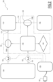
FIG. 3 is an exemplary system diagram of a supervision method implemented with the security system offigure 1 . - Aspects set forth below represent the necessary information to enable those skilled in the art to practice the disclosure.
-
FIG. 1 is anexemplary vehicle 10 according to an embodiment of the invention. Thevehicle 10 is a road vehicle and is configured to carry goods that fall under the ADR definition, in other words dangerous goods. In the illustrated example, thevehicle 10 is represented by a cistern truck and comprises acistern 12, which is arranged on top of achassis 14. Of course, the type ofvehicle 10 may vary, depending on the type of dangerous goods to be transported. Thevehicle 10 also comprises acabin 16 for a driver of thevehicle 10. - The
vehicle 10 comprises asecurity system 100, which is represented schematically onfigure 2 . Thesecurity system 100 comprises at least onesafety switch 102. Eachsafety switch 102 is configured to be activated by a user of thevehicle 10 when needed. In the illustrated example, thevehicle 10 comprises twosafety switches 102, with afirst safety switch 102 arranged inside thecabin 16, here on a dashboard 18, and asecond safety switch 102 arranged outside thecabin 16. In the illustrated example, the second safety switch 20 is arranged on the chassis 20 at a rear end of thevehicle 10. In the illustrated example, thesafety switches 102 are represented by pushbuttons. The number, location and shape of thesafety switches 102 are not limitative. - The
vehicle 10 comprises amain power source 104, for example a battery such as an acid-lead battery. Themain power source 104 is configured to store electric power, and to release, when needed, electric power. Thevehicle 10 also comprises asecondary power source 106, which is different from themain power source 104. For example, thesecondary power source 106 is a lithium-ion battery, which is configured to harvest electric energy generated while braking, or a solar panel, etc. - The
vehicle 10 also comprises anelectric load 110. According to non-limiting examples, theelectric load 110 is a pump, a compressor, a cooling system, etc. More generally, theelectric load 110 is a piece of equipment that is powered by electricity. Theelectric load 110 comprises afirst input line 114, which is connected to themain power source 104. Thefirst input line 114 is represented by a line onfigure 2 , with an arrow illustrating the flow of electric power, from themain power source 104 to theelectric load 110. Theelectric load 110 also comprises asecond input line 116, which is different from thefirst input line 114 and which is connected to thesecondary power source 106. - The
security system 100 also comprises an electronicmain control unit 120 and a first electronically operatedswitch 124. The first electronically operatedswitch 124 is arranged on thefirst input line 104, that is to say between themain power source 104 and theelectric load 110. The electronically operated switch124 is controlled by themain control unit 120 and is configured to switch between a connected configuration, where said electronically operatedswitch 124 allows electric current to flow between themain power source 104 and theelectric load 110, and a cutoff configuration, where the electronically operatedswitch 124 prevents electric current from circulating between themain power source 104 and theelectric load 110. The electronically operatedswitch 124 is schematically represented onfigure 2 . Preferably, the electronically operatedswitch 124 is a solid-state relay, for example a thyristor, which is controlled by themain control unit 120. - The
main control unit 120 is controlled by thesafety switch 102, so that the electronically operatedswitch 124 switches to its cutoff configuration when thesafety switch 102 is activated. According to some examples, eachsafety switch 102 is connected to themain control unit 120 through a data bus of thevehicle 10, such as a CAN bus. The data bus is not represented. More generally, any connection for data transmission may be done through a data bus of the vehicle, such as a CAN bus, while connection for electric power transmission are preferably done through dedicated electric wires. - The
security system 100 also comprises an electronicsafety control unit 130. Thesafety control unit 130 is different from themain control unit 120. Thesafety control unit 130 is powered by themain power source 104 through asupply line 135. - Preferably, the
supply line 135 of thesafety control unit 130 is controlled by themain control unit 120 through an additional electronically operatedswitch 125. The additional electronically operated switch is similar, preferably identical, to the other electronically operated switch(s) 124 associated to the electric load(s) 110. The additional electronically operatedswitch 125 is controlled by themain control unit 120, more precisely themain control unit 120 is configured to switch said additional electronically operatedswitch 125 in its cutoff configuration after a predetermined time interval after the safety switch is activated. - The
security system 100 also comprises at least onecurrent sensor 134, including afirst sensor 134A. In the illustrated example, thefirst sensor 134A is arranged on the first input and is schematically represented by a loop around thefirst input line 114. Thesafety control unit 130 is configured to receive data from eachcurrent sensor 134, for example data representing the intensity of an electric current measured by thesensor 134, or data representing whether an electric current is actually circulating or not. In a not shown alternative, thecurrent sensor 134A is integrated with the electronically operatedswitch 124 associated with thefirst input line 114. In another, not shown, alternative, the additional electronically operatedswitch 125 also integrates an additional current sensor. - The at least one
current sensor 134 advantageously includes asecond sensor 134B, which is different from thefirst sensor 134A and which is arranged on thesecond input line 116. Thesecond sensor 134B is configured to detect electric current circulating through thesecond input line 116. More generally, eachcurrent sensor 134 is arranged on a respective input line or supply line, eachcurrent sensor 134 being configured to detect electric current circulating through the corresponding line. - The
security system 100 also comprises alarm means 140. The alarm means 140 are configured to alert a user of thevehicle 10, in particular when said user presses one of the safety switches 102. In the illustrated example, the alarm means 140 include ahorn 142, arranged on the top of thecabin 16, abuzzer 144 arranged inside the cabin, andlights 146 arranged on thechassis 14. The number, location and types of alarm means 140 is not limitative. - Working principles of the
security system 100 are detailed hereinafter. - During normal operations of the
vehicle 10, the safety switches 102 are in a deactivated configuration, while thesafety control unit 130 is in a first mode, for example a waiting mode. The alarm means 140 are not activated, and the electronically operatedswitches - Advantageously, when the
safety control unit 130 is in the waiting mode, thesafety control unit 130 monitors the data received from eachcurrent sensors 134. In case of an abnormal situation, for example if the current value measured by any one of thecurrent sensors 134 rises above a predetermined threshold, then thesafety control unit 130 alerts a user of thevehicle 10. For example, thesafety control unit 130 activates the alarm means 140 in a specific way to alert the user without startling the user - especially if the user is driving. - When needed, for example when loading the
vehicle 10 with dangerous goods, or in case of an abnormal situation, a user triggers one of the safety switches 102. As one of the safety switches 102 is triggered, themain control unit 120 switches the electronically operatedswitch 124 to its cutoff configuration, in order to disconnect theelectric load 110 from themain power source 104. When thevehicle 10 comprises severalelectric loads 110, each associated with a respective electronically operatedswitch 124, then themain control unit 120 switches each electronically operatedswitch 124 to its cutoff configuration. - Also, when one of the safety switches 102 is activated, the
main control unit 120 activates thesafety control unit 130 to an active mode. When in the active mode, thesafety control unit 130 receives data from eachcurrent sensor 134. - If, after a predetermined first time interval from the moment the
safety switch 102 is activated, any one of thecurrent sensors 134 detects an electric current flowing through theinput line 114, then thesafety control unit 130 activates the alarm means 140, in order to alert the user that theelectric load 110 is not properly deactivated. An electric current flowing through theinput line 114 means that a current above a predetermined current threshold is circulating in said input line. For example, the predetermined current threshold is proportional to a sensitivity threshold of thecurrent sensor 134. - When the
security system 100 works properly, the first time interval is set to allow transient electrical phenomenon to disappear after each electronically operatedswitch 124 is switched to its cutoff configuration, in order to avoid false alarms. For example, the first time interval is equal to 50 ms - milliseconds - after thesafety switch 102 is activated. - Advantageously, after the
safety control unit 130 activates the alarm means 140, thesafety control unit 130 turns off the alarm means 140 after a predetermined second time interval. Preferably, the second time interval ends 200 ms - milliseconds - after thesafety switch 102 is activated, in order to fulfill ADR regulations. - Similarly, the
safety control unit 130 itself is also an electric equipment of thevehicle 10, and as such thesafety control unit 130 itself should fulfill ADR regulations. Preferably, when thesafety switch 102 is activated, themain control unit 120 is configured to switch the additional electronically operatedswitch 125 in its cutoff configuration after a predetermined third time interval after thesafety switch 102 is activated, so that thesafety control unit 130 itself is turned-off. Preferably, the third time interval is shorter than 200 ms, for example equal to 180 ms. - Advantageously, the
safety control unit 130 comprises a timer, configured to count the elapsed time after thesafety control unit 130 is switched to its active configuration until thesafety control unit 130 itself is turned off. If the elapsed time exceeds the third time interval, meaning that themain control unit 120 did not properly switch the additional electronically operatedswitch 125 to its cutoff configuration, then thesafety control unit 130 activates the alarm means 140. - Based on the example of the
security system 100 described above, the invention also concerns a supervision method to supervise the electric loads of thevehicle 10. This supervision method is preferably implemented using thesafety control unit 100 previously described. - With reference to
figure 3 , thesafety control unit 130 is initially in the waiting mode. Waiting mode is represented by abox 200. If thesafety switch 102 is activated, then thesafety control unit 130 switches to the activated mode. Activated mode is represented by abox 210. While in the activatedmode 210, thesafety control unit 130 receives data from thecurrent sensors 134. Reception of data is represented by abox 220. - If, after the predetermined first time interval from the moment the
safety switch 102 is activated, data received from thecurrent sensors 134 show that at least onecurrent sensor 134 detects electric current flowing through the corresponding input line, then thesafety control unit 130 activates the alarm means 140. Activation of the alarm means 140 is represented by abox 230. - The first time interval is longer that 10 ms, preferably longer that 20 ms, even more preferably longer than 40 ms. For example, the first time interval is equal to 50 ms.
- Advantageously, after the
safety control unit 130 activates the alarm means 140, thesafety control unit 130 turns off the alarm means 140 after a predetermined second time interval. The second time interval ends preferably 200 ms after the safety switch is activated. - Advantageously, when the
safety control unit 130 is in the active configuration, thesafety control unit 130 starts a timer, to count time elapsed since thesafety control unit 130 is switched to its active mode, until the power supply of thesafety control unit 130 is cut-off by the additional electronically operatedswitch 125, in other words until thesafety control unit 130 Is turned off. If the elapsed time reaches the predetermined third time interval, then thesafety control unit 130 activates the alarm means 140. itself is turned-off. Preferably, the third time interval is shorter than 200 ms. - The terminology used herein is for the purpose of describing particular aspects only and is not intended to be limiting of the disclosure. As used herein, the singular forms "a," "an," and "the" are intended to include the plural forms as well, unless the context clearly indicates otherwise. As used herein, the term "and/or" includes any and all combinations of one or more of the associated listed items. It will be further understood that the terms "comprises," "comprising," "includes," and/or "including" when used herein specify the presence of stated features, integers, steps, operations, elements, and/or components, but do not preclude the presence or addition of one or more other features, integers, steps, operations, elements, components, and/or groups thereof.
- It will be understood that, although the terms first, second, etc., may be used herein to describe various elements, these elements should not be limited by these terms. These terms are only used to distinguish one element from another. For example, a first element could be termed a second element, and, similarly, a second element could be termed a first element without departing from the scope of the present disclosure.
- Relative terms such as "below" or "above" or "upper" or "lower" or "horizontal" or "vertical" may be used herein to describe a relationship of one element to another element as illustrated in the Figures. It will be understood that these terms and those discussed above are intended to encompass different orientations of the device in addition to the orientation depicted in the Figures. It will be understood that when an element is referred to as being "connected" or "coupled" to another element, it can be directly connected or coupled to the other element, or intervening elements may be present. In contrast, when an element is referred to as being "directly connected" or "directly coupled" to another element, there are no intervening elements present.
- Unless otherwise defined, all terms (including technical and scientific terms) used herein have the same meaning as commonly understood by one of ordinary skill in the art to which this disclosure belongs. It will be further understood that terms used herein should be interpreted as having a meaning consistent with their meaning in the context of this specification and the relevant art and will not be interpreted in an idealized or overly formal sense unless expressly so defined herein.
- It is to be understood that the present disclosure is not limited to the aspects described above and illustrated in the drawings; rather, the skilled person will recognize that many changes and modifications may be made within the scope of the present disclosure and appended claims. In the drawings and specification, there have been disclosed aspects for purposes of illustration only and not for purposes of limitation, the scope of the inventive concepts being set forth in the following claims.
Claims (11)
- A security system circuit for a vehicle, the security system comprising:- an electronic main control unit,- at least one electronically operated switch, which is arranged on an input line of an electric load of the vehicle, each relay being controlled by the main control unit and being is configured to switch between:• a connected configuration, where said electronically operated switch allows electricity to flow through the input line between a main electric power source of the vehicle and the electric load, and• a cutoff configuration, where said electronically operated switch prevents electricity from circulating through the input line between the main power source and said electric load,- a safety switch, configured to be activated by a user of the vehicle, the safety switch being configured to control the main control unit, so that each electronically operated switch switches to its cutoff configuration when the safety switch is activated,wherein the security system further comprises:- an electronic safety control unit, which is different from the main control unit, the safety control unit being powered by the main power source,- at least one current sensor, each current sensor being is configured to detect electric current flowing through a respective input line of said electric load, and- alarm means, configured to alert a user of the vehicle,wherein the safety control unit is configured:- to change from a waiting mode to an active mode under the control of a main control unit of the vehicle, which is different from the safety control unit, the safety control unit changing to the active mode when the safety switch is activated, and- to activate the alarm means when:• the safety control unit is in the active mode, and• after a predetermined first time interval from the moment the safety switch is activated, at least one current sensor detects electric current flowing through the corresponding input line.
- The security system according to claim 1, wherein- after the safety control unit activates the alarm means, the safety control unit turns off the alarm means after a predetermined second time interval.
- The security system according to claim 2, wherein- the second time interval ends 200 ms after the safety switch is activated.
- The security system according to any one of claims 1 to 3, wherein- first time interval is equal to 50 ms after the safety switch is activated.
- The security system according to any one of claims 1 to 4, wherein- the electronically operated switchs include an additional electronically operated switch,- the power supply of the safety control unit is controlled by the main control unit through the additional electronically operated switch,- the main control unit is configured to switch said additional electronically operated switch in its cutoff configuration after a predetermined time interval after the safety switch is activated.
- A road vehicle, in particular a truck, comprising:- the security system according to any one of previous claims,- a main power source, for example a battery,- one electric load with at a first input line, which is connected to the main power source,wherein the at least one current sensor include a first sensor, which is arranged on the first input line.
- A road vehicle according to the previous claim, wherein:- the vehicle comprises an additional power source, for example a capacitor or a solar panel, the additional power source being different from the main power source,- the electric load comprises a second input line, which is different from the first input line and which is connected to the additional power source,wherein the at least one current sensor include a second sensor, which is arranged on the second input line.
- A supervision method to supervise electric accessories of a vehicle comprising the safety control unit according to any one of previous claims, the supervision method comprising the following steps:- after the safety switch is activated, obtaining information, from at least one current sensor that is arranged on a respective input line, regarding current flowing through the corresponding input line,- activating the alarm means if, after the predetermined first time interval from the moment the safety switch is activated, at least one current sensor detects electric current flowing through the corresponding input line.
- The supervision method according to the previous claim, comprising the following additional steps:- after activating the alarm means are activated, turning off alarm means after a predetermined second time interval.
- The supervision method according to the previous claim, wherein- the second time interval ends 200 ms after the safety switch is activated.
- The supervision method according to any one of claims 8 to 10, wherein:- the first time interval is equal to 50 ms.
Priority Applications (3)
| Application Number | Priority Date | Filing Date | Title |
|---|---|---|---|
| EP23150890.4A EP4401273B1 (en) | 2023-01-10 | 2023-01-10 | Security system for a vehicle, vehicle comprising such a security system and associated supervision method |
| US18/403,877 US12570154B2 (en) | 2023-01-10 | 2024-01-04 | Security system for a vehicle, vehicle comprising such a security system and associated supervision method |
| CN202410028284.9A CN118323025A (en) | 2023-01-10 | 2024-01-05 | Vehicle security system, vehicle including the security system and related supervision method |
Applications Claiming Priority (1)
| Application Number | Priority Date | Filing Date | Title |
|---|---|---|---|
| EP23150890.4A EP4401273B1 (en) | 2023-01-10 | 2023-01-10 | Security system for a vehicle, vehicle comprising such a security system and associated supervision method |
Publications (2)
| Publication Number | Publication Date |
|---|---|
| EP4401273A1 true EP4401273A1 (en) | 2024-07-17 |
| EP4401273B1 EP4401273B1 (en) | 2025-03-05 |
Family
ID=84923176
Family Applications (1)
| Application Number | Title | Priority Date | Filing Date |
|---|---|---|---|
| EP23150890.4A Active EP4401273B1 (en) | 2023-01-10 | 2023-01-10 | Security system for a vehicle, vehicle comprising such a security system and associated supervision method |
Country Status (3)
| Country | Link |
|---|---|
| US (1) | US12570154B2 (en) |
| EP (1) | EP4401273B1 (en) |
| CN (1) | CN118323025A (en) |
Citations (5)
| Publication number | Priority date | Publication date | Assignee | Title |
|---|---|---|---|---|
| WO2004078527A1 (en) * | 2003-03-04 | 2004-09-16 | Volvo Lastvagnar Ab | Adr unit |
| EP2309637A2 (en) * | 2009-09-07 | 2011-04-13 | Kobelco Construction Machinery Co. Ltd. | Current leakage detector of construction machine |
| EP3663137A1 (en) * | 2017-12-15 | 2020-06-10 | Hitachi Construction Machinery Co., Ltd. | Construction machine |
| US10958265B1 (en) * | 2020-01-07 | 2021-03-23 | Inpower Llc | Winch motor protection circuit |
| US20210143663A1 (en) * | 2019-11-08 | 2021-05-13 | Oshkosh Corporation | Power system for a vehicle |
-
2023
- 2023-01-10 EP EP23150890.4A patent/EP4401273B1/en active Active
-
2024
- 2024-01-04 US US18/403,877 patent/US12570154B2/en active Active
- 2024-01-05 CN CN202410028284.9A patent/CN118323025A/en active Pending
Patent Citations (5)
| Publication number | Priority date | Publication date | Assignee | Title |
|---|---|---|---|---|
| WO2004078527A1 (en) * | 2003-03-04 | 2004-09-16 | Volvo Lastvagnar Ab | Adr unit |
| EP2309637A2 (en) * | 2009-09-07 | 2011-04-13 | Kobelco Construction Machinery Co. Ltd. | Current leakage detector of construction machine |
| EP3663137A1 (en) * | 2017-12-15 | 2020-06-10 | Hitachi Construction Machinery Co., Ltd. | Construction machine |
| US20210143663A1 (en) * | 2019-11-08 | 2021-05-13 | Oshkosh Corporation | Power system for a vehicle |
| US10958265B1 (en) * | 2020-01-07 | 2021-03-23 | Inpower Llc | Winch motor protection circuit |
Also Published As
| Publication number | Publication date |
|---|---|
| US12570154B2 (en) | 2026-03-10 |
| CN118323025A (en) | 2024-07-12 |
| US20240227567A1 (en) | 2024-07-11 |
| EP4401273B1 (en) | 2025-03-05 |
Similar Documents
| Publication | Publication Date | Title |
|---|---|---|
| US11400903B2 (en) | Brake control unit | |
| US8502409B2 (en) | Power supply control apparatus | |
| US3522481A (en) | Storage battery protective device | |
| CN108340855B (en) | Control method and control device for power supply main switch of vehicle | |
| WO2015060674A1 (en) | Forklift managing device | |
| EP3960523B1 (en) | Working vehicle | |
| CN116767117B (en) | Vehicle control system, method, controller, and storage medium | |
| EP4401273A1 (en) | Security system for a vehicle, vehicle comprising such a security system and associated supervision method | |
| KR102481210B1 (en) | Method for checking high voltage battery status in sleep mode of electric vehicle | |
| JPH1199889A (en) | Electronic control device for vehicles | |
| CN116766938A (en) | Vehicle collision safety protection system, method, vehicle and medium | |
| US11618325B2 (en) | Diagnosis of the active discharge of a HV intermediate circuit | |
| JP2003226208A (en) | Power supply system for vehicles | |
| CN106877490A (en) | A vehicle and its power supply emergency cut-off protection system | |
| CN105904968A (en) | Load limiting system for electric vehicle | |
| JPH10194007A (en) | Power supply cutoff device at the time of vehicle collision | |
| EP3541670B1 (en) | Landing gear system and method of operating a landing gear system for a vehicle trailer | |
| KR101692079B1 (en) | System for shuting off power and alarming for a heavy equipment and control method thereof | |
| CN218085088U (en) | Battery over-discharge prevention device and vehicle | |
| CN205239312U (en) | Tipper integration lifts alarm device | |
| KR20170115410A (en) | Method for alarming lamp open of vehicle | |
| KR100831724B1 (en) | Automotive Power Disconnect Device | |
| CN112684752A (en) | Cab turnover test device and test method | |
| CN223966947U (en) | Alarm control system and battery alarm system | |
| JP7729302B2 (en) | Vehicle monitoring device |
Legal Events
| Date | Code | Title | Description |
|---|---|---|---|
| PUAI | Public reference made under article 153(3) epc to a published international application that has entered the european phase |
Free format text: ORIGINAL CODE: 0009012 |
|
| STAA | Information on the status of an ep patent application or granted ep patent |
Free format text: STATUS: THE APPLICATION HAS BEEN PUBLISHED |
|
| AK | Designated contracting states |
Kind code of ref document: A1 Designated state(s): AL AT BE BG CH CY CZ DE DK EE ES FI FR GB GR HR HU IE IS IT LI LT LU LV MC ME MK MT NL NO PL PT RO RS SE SI SK SM TR |
|
| STAA | Information on the status of an ep patent application or granted ep patent |
Free format text: STATUS: REQUEST FOR EXAMINATION WAS MADE |
|
| 17P | Request for examination filed |
Effective date: 20240819 |
|
| RBV | Designated contracting states (corrected) |
Designated state(s): AL AT BE BG CH CY CZ DE DK EE ES FI FR GB GR HR HU IE IS IT LI LT LU LV MC ME MK MT NL NO PL PT RO RS SE SI SK SM TR |
|
| REG | Reference to a national code |
Ref country code: DE Ref legal event code: R079 Free format text: PREVIOUS MAIN CLASS: H02J0007000000 Ipc: B60R0016030000 Ref document number: 602023002238 Country of ref document: DE |
|
| GRAP | Despatch of communication of intention to grant a patent |
Free format text: ORIGINAL CODE: EPIDOSNIGR1 |
|
| STAA | Information on the status of an ep patent application or granted ep patent |
Free format text: STATUS: GRANT OF PATENT IS INTENDED |
|
| RIC1 | Information provided on ipc code assigned before grant |
Ipc: H01H 9/16 20060101ALI20241111BHEP Ipc: H02J 7/00 20060101ALI20241111BHEP Ipc: B60R 16/03 20060101AFI20241111BHEP |
|
| INTG | Intention to grant announced |
Effective date: 20241126 |
|
| GRAS | Grant fee paid |
Free format text: ORIGINAL CODE: EPIDOSNIGR3 |
|
| GRAA | (expected) grant |
Free format text: ORIGINAL CODE: 0009210 |
|
| STAA | Information on the status of an ep patent application or granted ep patent |
Free format text: STATUS: THE PATENT HAS BEEN GRANTED |
|
| AK | Designated contracting states |
Kind code of ref document: B1 Designated state(s): AL AT BE BG CH CY CZ DE DK EE ES FI FR GB GR HR HU IE IS IT LI LT LU LV MC ME MK MT NL NO PL PT RO RS SE SI SK SM TR |
|
| REG | Reference to a national code |
Ref country code: GB Ref legal event code: FG4D |
|
| REG | Reference to a national code |
Ref country code: CH Ref legal event code: EP |
|
| REG | Reference to a national code |
Ref country code: DE Ref legal event code: R096 Ref document number: 602023002238 Country of ref document: DE |
|
| REG | Reference to a national code |
Ref country code: IE Ref legal event code: FG4D |
|
| PG25 | Lapsed in a contracting state [announced via postgrant information from national office to epo] |
Ref country code: RS Free format text: LAPSE BECAUSE OF FAILURE TO SUBMIT A TRANSLATION OF THE DESCRIPTION OR TO PAY THE FEE WITHIN THE PRESCRIBED TIME-LIMIT Effective date: 20250605 |
|
| PG25 | Lapsed in a contracting state [announced via postgrant information from national office to epo] |
Ref country code: FI Free format text: LAPSE BECAUSE OF FAILURE TO SUBMIT A TRANSLATION OF THE DESCRIPTION OR TO PAY THE FEE WITHIN THE PRESCRIBED TIME-LIMIT Effective date: 20250305 |
|
| REG | Reference to a national code |
Ref country code: NL Ref legal event code: MP Effective date: 20250305 |
|
| PG25 | Lapsed in a contracting state [announced via postgrant information from national office to epo] |
Ref country code: ES Free format text: LAPSE BECAUSE OF FAILURE TO SUBMIT A TRANSLATION OF THE DESCRIPTION OR TO PAY THE FEE WITHIN THE PRESCRIBED TIME-LIMIT Effective date: 20250305 |
|
| REG | Reference to a national code |
Ref country code: LT Ref legal event code: MG9D |
|
| PG25 | Lapsed in a contracting state [announced via postgrant information from national office to epo] |
Ref country code: NO Free format text: LAPSE BECAUSE OF FAILURE TO SUBMIT A TRANSLATION OF THE DESCRIPTION OR TO PAY THE FEE WITHIN THE PRESCRIBED TIME-LIMIT Effective date: 20250605 |
|
| PG25 | Lapsed in a contracting state [announced via postgrant information from national office to epo] |
Ref country code: HR Free format text: LAPSE BECAUSE OF FAILURE TO SUBMIT A TRANSLATION OF THE DESCRIPTION OR TO PAY THE FEE WITHIN THE PRESCRIBED TIME-LIMIT Effective date: 20250305 |
|
| PG25 | Lapsed in a contracting state [announced via postgrant information from national office to epo] |
Ref country code: LV Free format text: LAPSE BECAUSE OF FAILURE TO SUBMIT A TRANSLATION OF THE DESCRIPTION OR TO PAY THE FEE WITHIN THE PRESCRIBED TIME-LIMIT Effective date: 20250305 |
|
| PG25 | Lapsed in a contracting state [announced via postgrant information from national office to epo] |
Ref country code: BG Free format text: LAPSE BECAUSE OF FAILURE TO SUBMIT A TRANSLATION OF THE DESCRIPTION OR TO PAY THE FEE WITHIN THE PRESCRIBED TIME-LIMIT Effective date: 20250305 Ref country code: GR Free format text: LAPSE BECAUSE OF FAILURE TO SUBMIT A TRANSLATION OF THE DESCRIPTION OR TO PAY THE FEE WITHIN THE PRESCRIBED TIME-LIMIT Effective date: 20250606 |
|
| PG25 | Lapsed in a contracting state [announced via postgrant information from national office to epo] |
Ref country code: NL Free format text: LAPSE BECAUSE OF FAILURE TO SUBMIT A TRANSLATION OF THE DESCRIPTION OR TO PAY THE FEE WITHIN THE PRESCRIBED TIME-LIMIT Effective date: 20250305 |
|
| PG25 | Lapsed in a contracting state [announced via postgrant information from national office to epo] |
Ref country code: SE Free format text: LAPSE BECAUSE OF FAILURE TO SUBMIT A TRANSLATION OF THE DESCRIPTION OR TO PAY THE FEE WITHIN THE PRESCRIBED TIME-LIMIT Effective date: 20250305 |
|
| PG25 | Lapsed in a contracting state [announced via postgrant information from national office to epo] |
Ref country code: SM Free format text: LAPSE BECAUSE OF FAILURE TO SUBMIT A TRANSLATION OF THE DESCRIPTION OR TO PAY THE FEE WITHIN THE PRESCRIBED TIME-LIMIT Effective date: 20250305 |
|
| PG25 | Lapsed in a contracting state [announced via postgrant information from national office to epo] |
Ref country code: PT Free format text: LAPSE BECAUSE OF FAILURE TO SUBMIT A TRANSLATION OF THE DESCRIPTION OR TO PAY THE FEE WITHIN THE PRESCRIBED TIME-LIMIT Effective date: 20250707 |
|
| PG25 | Lapsed in a contracting state [announced via postgrant information from national office to epo] |
Ref country code: IT Free format text: LAPSE BECAUSE OF FAILURE TO SUBMIT A TRANSLATION OF THE DESCRIPTION OR TO PAY THE FEE WITHIN THE PRESCRIBED TIME-LIMIT Effective date: 20250305 Ref country code: PL Free format text: LAPSE BECAUSE OF FAILURE TO SUBMIT A TRANSLATION OF THE DESCRIPTION OR TO PAY THE FEE WITHIN THE PRESCRIBED TIME-LIMIT Effective date: 20250305 |
|
| PG25 | Lapsed in a contracting state [announced via postgrant information from national office to epo] |
Ref country code: AT Free format text: LAPSE BECAUSE OF FAILURE TO SUBMIT A TRANSLATION OF THE DESCRIPTION OR TO PAY THE FEE WITHIN THE PRESCRIBED TIME-LIMIT Effective date: 20250305 |
|
| PG25 | Lapsed in a contracting state [announced via postgrant information from national office to epo] |
Ref country code: CZ Free format text: LAPSE BECAUSE OF FAILURE TO SUBMIT A TRANSLATION OF THE DESCRIPTION OR TO PAY THE FEE WITHIN THE PRESCRIBED TIME-LIMIT Effective date: 20250305 Ref country code: EE Free format text: LAPSE BECAUSE OF FAILURE TO SUBMIT A TRANSLATION OF THE DESCRIPTION OR TO PAY THE FEE WITHIN THE PRESCRIBED TIME-LIMIT Effective date: 20250305 |
|
| PG25 | Lapsed in a contracting state [announced via postgrant information from national office to epo] |
Ref country code: RO Free format text: LAPSE BECAUSE OF FAILURE TO SUBMIT A TRANSLATION OF THE DESCRIPTION OR TO PAY THE FEE WITHIN THE PRESCRIBED TIME-LIMIT Effective date: 20250305 |
|
| PG25 | Lapsed in a contracting state [announced via postgrant information from national office to epo] |
Ref country code: SK Free format text: LAPSE BECAUSE OF FAILURE TO SUBMIT A TRANSLATION OF THE DESCRIPTION OR TO PAY THE FEE WITHIN THE PRESCRIBED TIME-LIMIT Effective date: 20250305 |
|
| PG25 | Lapsed in a contracting state [announced via postgrant information from national office to epo] |
Ref country code: IS Free format text: LAPSE BECAUSE OF FAILURE TO SUBMIT A TRANSLATION OF THE DESCRIPTION OR TO PAY THE FEE WITHIN THE PRESCRIBED TIME-LIMIT Effective date: 20250705 |
|
| REG | Reference to a national code |
Ref country code: DE Ref legal event code: R097 Ref document number: 602023002238 Country of ref document: DE |
|
| PLBE | No opposition filed within time limit |
Free format text: ORIGINAL CODE: 0009261 |
|
| STAA | Information on the status of an ep patent application or granted ep patent |
Free format text: STATUS: NO OPPOSITION FILED WITHIN TIME LIMIT |
|
| PG25 | Lapsed in a contracting state [announced via postgrant information from national office to epo] |
Ref country code: DK Free format text: LAPSE BECAUSE OF FAILURE TO SUBMIT A TRANSLATION OF THE DESCRIPTION OR TO PAY THE FEE WITHIN THE PRESCRIBED TIME-LIMIT Effective date: 20250305 |
|
| REG | Reference to a national code |
Ref country code: CH Ref legal event code: L10 Free format text: ST27 STATUS EVENT CODE: U-0-0-L10-L00 (AS PROVIDED BY THE NATIONAL OFFICE) Effective date: 20260114 |
|
| 26N | No opposition filed |
Effective date: 20251208 |
|
| PGFP | Annual fee paid to national office [announced via postgrant information from national office to epo] |
Ref country code: DE Payment date: 20260127 Year of fee payment: 4 |
|
| PGFP | Annual fee paid to national office [announced via postgrant information from national office to epo] |
Ref country code: FR Payment date: 20260126 Year of fee payment: 4 |