EP4401221A1 - Battery, battery pack, and vehicle - Google Patents
Battery, battery pack, and vehicle Download PDFInfo
- Publication number
- EP4401221A1 EP4401221A1 EP22897697.3A EP22897697A EP4401221A1 EP 4401221 A1 EP4401221 A1 EP 4401221A1 EP 22897697 A EP22897697 A EP 22897697A EP 4401221 A1 EP4401221 A1 EP 4401221A1
- Authority
- EP
- European Patent Office
- Prior art keywords
- channel
- battery
- battery core
- potting
- end plate
- Prior art date
- Legal status (The legal status is an assumption and is not a legal conclusion. Google has not performed a legal analysis and makes no representation as to the accuracy of the status listed.)
- Pending
Links
Images



Classifications
-
- H—ELECTRICITY
- H01—ELECTRIC ELEMENTS
- H01M—PROCESSES OR MEANS, e.g. BATTERIES, FOR THE DIRECT CONVERSION OF CHEMICAL ENERGY INTO ELECTRICAL ENERGY
- H01M50/00—Constructional details or processes of manufacture of the non-active parts of electrochemical cells other than fuel cells, e.g. hybrid cells
- H01M50/20—Mountings; Secondary casings or frames; Racks, modules or packs; Suspension devices; Shock absorbers; Transport or carrying devices; Holders
- H01M50/249—Mountings; Secondary casings or frames; Racks, modules or packs; Suspension devices; Shock absorbers; Transport or carrying devices; Holders specially adapted for aircraft or vehicles, e.g. cars or trains
-
- H—ELECTRICITY
- H01—ELECTRIC ELEMENTS
- H01M—PROCESSES OR MEANS, e.g. BATTERIES, FOR THE DIRECT CONVERSION OF CHEMICAL ENERGY INTO ELECTRICAL ENERGY
- H01M50/00—Constructional details or processes of manufacture of the non-active parts of electrochemical cells other than fuel cells, e.g. hybrid cells
- H01M50/10—Primary casings; Jackets or wrappings
- H01M50/102—Primary casings; Jackets or wrappings characterised by their shape or physical structure
- H01M50/103—Primary casings; Jackets or wrappings characterised by their shape or physical structure prismatic or rectangular
-
- H—ELECTRICITY
- H01—ELECTRIC ELEMENTS
- H01M—PROCESSES OR MEANS, e.g. BATTERIES, FOR THE DIRECT CONVERSION OF CHEMICAL ENERGY INTO ELECTRICAL ENERGY
- H01M50/00—Constructional details or processes of manufacture of the non-active parts of electrochemical cells other than fuel cells, e.g. hybrid cells
- H01M50/10—Primary casings; Jackets or wrappings
- H01M50/183—Sealing members
- H01M50/184—Sealing members characterised by their shape or structure
-
- H—ELECTRICITY
- H01—ELECTRIC ELEMENTS
- H01M—PROCESSES OR MEANS, e.g. BATTERIES, FOR THE DIRECT CONVERSION OF CHEMICAL ENERGY INTO ELECTRICAL ENERGY
- H01M50/00—Constructional details or processes of manufacture of the non-active parts of electrochemical cells other than fuel cells, e.g. hybrid cells
- H01M50/10—Primary casings; Jackets or wrappings
- H01M50/183—Sealing members
- H01M50/186—Sealing members characterised by the disposition of the sealing members
-
- H—ELECTRICITY
- H01—ELECTRIC ELEMENTS
- H01M—PROCESSES OR MEANS, e.g. BATTERIES, FOR THE DIRECT CONVERSION OF CHEMICAL ENERGY INTO ELECTRICAL ENERGY
- H01M50/00—Constructional details or processes of manufacture of the non-active parts of electrochemical cells other than fuel cells, e.g. hybrid cells
- H01M50/20—Mountings; Secondary casings or frames; Racks, modules or packs; Suspension devices; Shock absorbers; Transport or carrying devices; Holders
- H01M50/233—Mountings; Secondary casings or frames; Racks, modules or packs; Suspension devices; Shock absorbers; Transport or carrying devices; Holders characterised by physical properties of casings or racks, e.g. dimensions
- H01M50/24—Mountings; Secondary casings or frames; Racks, modules or packs; Suspension devices; Shock absorbers; Transport or carrying devices; Holders characterised by physical properties of casings or racks, e.g. dimensions adapted for protecting batteries from their environment, e.g. from corrosion
-
- H—ELECTRICITY
- H01—ELECTRIC ELEMENTS
- H01M—PROCESSES OR MEANS, e.g. BATTERIES, FOR THE DIRECT CONVERSION OF CHEMICAL ENERGY INTO ELECTRICAL ENERGY
- H01M50/00—Constructional details or processes of manufacture of the non-active parts of electrochemical cells other than fuel cells, e.g. hybrid cells
- H01M50/20—Mountings; Secondary casings or frames; Racks, modules or packs; Suspension devices; Shock absorbers; Transport or carrying devices; Holders
- H01M50/233—Mountings; Secondary casings or frames; Racks, modules or packs; Suspension devices; Shock absorbers; Transport or carrying devices; Holders characterised by physical properties of casings or racks, e.g. dimensions
- H01M50/242—Mountings; Secondary casings or frames; Racks, modules or packs; Suspension devices; Shock absorbers; Transport or carrying devices; Holders characterised by physical properties of casings or racks, e.g. dimensions adapted for protecting batteries against vibrations, collision impact or swelling
-
- H—ELECTRICITY
- H01—ELECTRIC ELEMENTS
- H01M—PROCESSES OR MEANS, e.g. BATTERIES, FOR THE DIRECT CONVERSION OF CHEMICAL ENERGY INTO ELECTRICAL ENERGY
- H01M50/00—Constructional details or processes of manufacture of the non-active parts of electrochemical cells other than fuel cells, e.g. hybrid cells
- H01M50/20—Mountings; Secondary casings or frames; Racks, modules or packs; Suspension devices; Shock absorbers; Transport or carrying devices; Holders
- H01M50/244—Secondary casings; Racks; Suspension devices; Carrying devices; Holders characterised by their mounting method
-
- H—ELECTRICITY
- H01—ELECTRIC ELEMENTS
- H01M—PROCESSES OR MEANS, e.g. BATTERIES, FOR THE DIRECT CONVERSION OF CHEMICAL ENERGY INTO ELECTRICAL ENERGY
- H01M50/00—Constructional details or processes of manufacture of the non-active parts of electrochemical cells other than fuel cells, e.g. hybrid cells
- H01M50/20—Mountings; Secondary casings or frames; Racks, modules or packs; Suspension devices; Shock absorbers; Transport or carrying devices; Holders
- H01M50/262—Mountings; Secondary casings or frames; Racks, modules or packs; Suspension devices; Shock absorbers; Transport or carrying devices; Holders with fastening means, e.g. locks
-
- H—ELECTRICITY
- H01—ELECTRIC ELEMENTS
- H01M—PROCESSES OR MEANS, e.g. BATTERIES, FOR THE DIRECT CONVERSION OF CHEMICAL ENERGY INTO ELECTRICAL ENERGY
- H01M50/00—Constructional details or processes of manufacture of the non-active parts of electrochemical cells other than fuel cells, e.g. hybrid cells
- H01M50/60—Arrangements or processes for filling or topping-up with liquids; Arrangements or processes for draining liquids from casings
- H01M50/609—Arrangements or processes for filling with liquid, e.g. electrolytes
- H01M50/627—Filling ports
-
- H—ELECTRICITY
- H01—ELECTRIC ELEMENTS
- H01M—PROCESSES OR MEANS, e.g. BATTERIES, FOR THE DIRECT CONVERSION OF CHEMICAL ENERGY INTO ELECTRICAL ENERGY
- H01M2220/00—Batteries for particular applications
- H01M2220/20—Batteries in motive systems, e.g. vehicle, ship, plane
-
- Y—GENERAL TAGGING OF NEW TECHNOLOGICAL DEVELOPMENTS; GENERAL TAGGING OF CROSS-SECTIONAL TECHNOLOGIES SPANNING OVER SEVERAL SECTIONS OF THE IPC; TECHNICAL SUBJECTS COVERED BY FORMER USPC CROSS-REFERENCE ART COLLECTIONS [XRACs] AND DIGESTS
- Y02—TECHNOLOGIES OR APPLICATIONS FOR MITIGATION OR ADAPTATION AGAINST CLIMATE CHANGE
- Y02E—REDUCTION OF GREENHOUSE GAS [GHG] EMISSIONS, RELATED TO ENERGY GENERATION, TRANSMISSION OR DISTRIBUTION
- Y02E60/00—Enabling technologies; Technologies with a potential or indirect contribution to GHG emissions mitigation
- Y02E60/10—Energy storage using batteries
Definitions
- the present disclosure relates to the technical field of batteries, and more specifically, to a battery, a battery pack, and a vehicle.
- components such as a battery core assembly are arranged in a battery.
- the components such as the battery core assembly are fixed by arranging a support in the battery, to implement fixing and mounting of the battery.
- the support arranged in the battery occupies a space, and has a complex assembly manner. If the battery encounters vibration or the like, the support easily becomes loosened, which affects safety performance of the battery. Therefore, for some batteries, a potting adhesive is injected therein to realize fixing and mounting of the batteries.
- the potting adhesive has large fluidity before curing, the safety performance of the batteries is affected if the potting adhesive flows to other positions.
- An object of the present disclosure is to provide a battery, a battery pack, and a vehicle.
- the battery pack in an embodiment of a first aspect of the present disclosure includes a housing and a battery core assembly.
- the housing includes a housing body and a first end plate and a second end plate opposite to each other in a length direction of the housing body.
- the first end plate, the second end plate, and the housing body define a hermetic accommodating cavity.
- An adhesive injection port is formed on the second end plate.
- the battery core assembly is arranged in the accommodating cavity.
- the battery core assembly includes a first surface. The first surface is opposite to a side of the housing body in a height direction of the housing body.
- a gap exists between the second end plate and the battery core assembly.
- a sealing member is arranged in the gap. The sealing member separates the gap into a first channel and a second channel.
- the adhesive injection port is in communication with the first channel.
- a potting channel is provided in the housing.
- the potting channel includes the first channel and a third channel located between the first surface and an inner wall of the housing body.
- the potting channel and the sealing member are arranged in the housing, and the sealing member separates the gap, so that the potting adhesive injected through the adhesive injection port can flow to the third channel through the first channel, thereby filling the potting channel.
- the battery core assembly in the battery is fixed, which improves reliability of an internal structure of the battery.
- an air suction port is formed on the first end plate.
- the air suction port is in communication with the potting channel, so that pressure in the potting channel is less than pressure outside the housing.
- an air inlet spaced apart from the adhesive injection port is further formed on the second end plate.
- the air inlet is in communication with the second channel.
- the battery core assembly further includes a second surface opposite the first surface.
- An air suction channel is provided in the housing.
- the air suction channel includes the second channel, a fourth channel located between the second surface and the inner wall of the housing body, and a fifth channel located between the first end plate and the battery core assembly.
- the fifth channel is in communication with the air suction port.
- the adhesive injection port and the air suction port are aligned with each other in the length direction of the housing.
- the battery core assembly includes a third surface and a fourth surface opposite to each other in a width direction of the housing body. At least an outer periphery of the fourth surface and at least an outer periphery of the third surface are snugly attached to the housing body.
- the battery core assembly includes a battery core unit and a protective film.
- the protective film is wrapped on an outer peripheral side of the battery core unit.
- the ends of the protective film in the length direction of the housing body are open.
- At least one through hole is formed on the protective film.
- the through hole is provided at least on a side of the protective film facing the third channel.
- a height of the housing is D 1 .
- the housing has two outer surfaces opposite to each other in the height direction.
- a distance between one of the two outer surfaces adjacent to the potting channel and a center of the adhesive injection port is D 2 .
- D 1 and D 2 meet a relationship of 10 mm ⁇ D 2 ⁇ 0.25D 1 .
- a distance between one of the two outer surfaces adjacent to the potting channel and a center of the air inlet is D 3 .
- D 2 and D 3 meet a relationship of D 2 + 18 mm ⁇ D 3 ⁇ D 2 + 22 mm.
- the battery core assembly includes the battery core unit, a battery core support, and an insulating member.
- the battery core unit includes multiple subunits arranged in the length direction of the housing and connected in series. One of the multiple subunits adjacent to the second end plate is a first subunit.
- the battery core support is fixed at an end of the first subunit facing the second end plate.
- the insulating member is arranged between the battery core support and the second end plate. The sealing member is sandwiched between the second end plate and the insulating member.
- At least one hook is arranged on one of the insulating member and the battery core support.
- At least one engagement hole is provided on the other of the insulating member and the battery core support. The hook is fitted in the engagement hole.
- a height of the potting adhesive in the height direction of the housing is D 4 .
- D 4 meets 0.8 mm ⁇ D 4 ⁇ 1.5 mm.
- the battery pack in an embodiment of a second aspect of the present disclosure includes the battery in any of the foregoing embodiments.
- the vehicle in an embodiment of a third aspect of the present disclosure includes the battery pack in the foregoing embodiment or the battery in any of the foregoing embodiments.
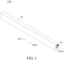
- a battery 100 in an embodiment of the present disclosure is described below with reference to FIG. 1 to FIG. 10 .
- the battery includes a housing 10 and a battery core assembly 20.
- a length direction is a left-right direction shown in FIG. 2
- a height direction is an up-down direction shown in FIG. 2
- a width direction is a front-rear direction shown in FIG. 2 .
- the housing 10 includes a housing body 16 and a first end plate 11 and a second end plate 12 opposite to each other in a length direction of the housing body 16.
- the first end plate 11, the second end plate 12, and the housing body 16 define a hermetic accommodating cavity 17.
- An adhesive injection port 14 is formed on the second end plate 12.
- the battery core assembly 20 is arranged in the accommodating cavity 17.
- the battery core assembly 20 includes a first surface 21.
- the first surface 21 is opposite to a side of the housing body 16 in a height direction of the housing body 16.
- a gap 50 exists between the second end plate 12 and the battery core assembly 20.
- a sealing member 23 is arranged in the gap 50. The sealing member 23 separates the gap 50 into a first channel a and a second channel b.
- the adhesive injection port 14 is in communication with the first channel a.
- a potting channel 30 is provided in the housing 10.
- the potting channel 30 includes the first channel a and a third channel c located between the first surface 21 and an inner wall of the housing body 16.
- a potting adhesive 31 is arranged in the potting channel 30.
- the first end plate 11 and the second end plate 12 may be respectively located at two ends in the length direction of the battery core assembly 20.
- the adhesive injection port 14 is formed on the second end plate 12.
- the battery core assembly 20 is located in the accommodating cavity 17.
- the first surface 21 is a surface of the battery core assembly 20 located below.
- An inner surface of the second end plate 12, the sealing member 23, and the battery core assembly 20 jointly define the first channel a.
- the first surface 21 of the battery core assembly 20 and an inner surface of a lower portion of the housing body 16 jointly define the third channel c.
- Apart of the potting channel 30 close to a left side and in communication with the adhesive injection port 14 is the first channel a, and a part of the potting channel 30 opposite the first surface 21 is the third channel c.
- the sealing member 23 is arranged between the second end plate 12 and the battery core assembly 20, to seal the gap between the second end plate 12 and the battery core assembly 20.
- the sealing member 23 can separate the gap 50 into the first channel a and the second channel b respectively located on an upper side and a lower side.
- the sealing member 23 may be made of foam.
- the sealing member 23 made of foam has good elasticity and compressibility, which can ensure isolation between the first channel a and the second channel b. For example, when the battery 100 encounters external factors such as vibration, the sealing member 23 can absorb the vibration to ensure that a sealing effect is not affected.
- the potting channel 30 and the sealing member 23 are arranged in the housing 10, and the sealing member 23 separates the gap 50, so that the potting adhesive 31 injected through the adhesive injection port 14 can flow to the third channel c through the first channel a, thereby filling the potting channel 30.
- fixing and sealing are realized in the battery 100, and quick positioning can be realized, which facilitates automatic potting, and improves reliability of an internal structure of the battery 100.
- an air suction port 13 is formed on the first end plate 11.
- the air suction port 13 is in communication with the potting channel 30, so that pressure in the potting channel 30 is less than pressure outside the housing 10. Since two ends of the potting channel 30 are respectively in communication with the adhesive injection port 14 and the air suction port 13, and the pressure in the potting channel 30 is less than atmospheric pressure outside the housing 10, the potting adhesive 31 may enter the potting channel 30 through the adhesive injection port 14, and can flow in the potting channel 30.
- the potting adhesive 31 is injected into the potting channel 30, so that multiple components in the battery 100 can be fixed through the potting adhesive 31 after curing, thereby ensuring structural reliability of the battery 100.
- Vacuumization is performed at the air suction port 13 to generate negative pressure in the potting channel 30.
- the "negative pressure” is an air pressure state lower than normal pressure.
- the potting adhesive 31 is injected into the housing 10 at the adhesive injection port 14.
- the potting adhesive 31 can move from an end of the potting channel 30 in communication with the adhesive injection port 14 to an end of the potting channel 30 in communication with the air suction port 13 through an adsorption force of the negative pressure, so that the potting adhesive 31 can fill the potting channel 30.
- the air suction port 13 is formed on the first end plate 11, the air suction port 13 is in communication with the potting channel 30, and air suction may be performed at the air suction port 13 to reduce the pressure in the potting channel 30, so that the potting adhesive 31 can smoothly flow into the potting channel 30, which not only improves potting efficiency, but also realizes good flow uniformity for the potting adhesive 31.
- an air inlet 15 spaced apart from the adhesive injection port 14 is further formed on the second end plate 12.
- the air inlet 15 is in communication with the second channel b.
- the battery core assembly 20 further includes a second surface 22 opposite the first surface 21.
- An air suction channel 40 is provided in the housing 10.
- the air suction channel 40 includes the second channel b, a fourth channel d located between the second surface 22 and the inner wall of the housing 10, and a fifth channel e located between the first end plate 11 and the battery core assembly 20.
- the fifth channel e is in communication with the air suction port 13.
- the air suction channel 40 and the potting channel 30 are isolated by the sealing member 23 at the second end plate 12, and are spaced apart in a height direction of the battery 100. Two ends of the air suction channel 40 are respectively in communication with the air inlet 15 and the air suction port 13, to form an airflow circulation channel.
- the air suction channel 40 is provided in the housing 10, one end of the air suction channel 40 is in communication with the air inlet 15, and the other end is in communication with the air suction port 13.
- air pressure in the air suction channel 40 is greater than air pressure in the potting channel 30, so that the potting adhesive 31 of the potting channel 30 is prevented from partially flowing toward the air suction channel 40, which can reduce use of the potting adhesive 31, facilitate injection of the potting adhesive 31, and reduce costs for manufacturing the battery 100. That the air suction channel 40 is in communication with the outside through the air inlet 15 may be as follows.
- the air inlet 15 is not sealed during the vacuumization, and therefore, the air pressure in the air suction channel 40 is equal to the atmospheric pressure, so that the air pressure in the air suction channel 40 is greater than the air pressure in the potting channel 30.
- the air inlet 15 may be in communication with an external air supply tank, so that the air pressure in the air suction channel 40 is greater than the air pressure in the potting channel 30.
- the first surface 21 and the second surface 22 are opposite to each other in the height direction.
- the first end plate 11 and the second end plate 12 may be two end plates opposite to each other shown in FIG. 2 in the left-right direction.
- the first surface 21 and the second surface 22 may be two surfaces opposite to each other shown in FIG. 2 and FIG. 5 in the up-down direction.
- the battery core assembly 20 may further include a protective film 28.
- the protective film 28 is wrapped on an outer peripheral side of a battery core unit 24, and the left and right ends of the protective film 28 shown in FIG. 2 are open, so that the left and right ends of the battery core unit 24 shown in FIG. 2 are exposed.
- the protective film 28 can protect the battery core unit 24 from external corrosion and protect an outer surface of the battery core unit 24 from scratches.
- At least one through hole 281 is formed on the protective film 28.
- the through hole 281 is provided at least on a side of the protective film 28 facing the third channel c.
- the battery core assembly 20 may include a third surface and a fourth surface (not shown in the figure) opposite to each other in a width direction. At least an outer periphery of the fourth surface and at least an outer periphery of the third surface 27 are snugly attached to the housing body 16, which can prevent the potting adhesive 31 from flowing to the third surface 27 and the fourth surface.
- the third surface 27 and the fourth surface may be arranged to snugly hold the housing body 16 through pressing or the like without interfering with the air suction channel 40 and the potting channel 30. In this way, not only is snug attachment between the third surface 27 and the housing body 16 ensured, but also isolation between the potting channel 30 and the air suction channel 40 is realized, which improves safety performance of the battery 100.
- the first surface 21 may be constructed from a surface of the protective film 28 facing a side of the housing body 16 (for example, a lower side shown in FIG. 2 and FIG. 3 ), and the second surface 22 may be constructed from a surface of the protective film 28 facing another other side of the housing body (for example, an upper side shown in FIG. 2 and FIG. 3 ).
- the first surface 21 and the second surface 22 are two surfaces of the protective film 28 opposite to each other in the height direction of the housing body 16 (or the height direction of the battery 100).
- the third surface 27 may be constructed from a surface of the protective film 28 facing a side of the housing body 16 (for example, a front side shown in FIG.
- the fourth surface may be constructed from a surface of the protective film 28 facing another side of the housing body 16 (for example, a rear side as shown in FIG. 2 ).
- the third surface 27 and the fourth surface are two surfaces of the protective film opposite to each other in the width direction of the housing body 16 (that is, a thickness direction of the battery 100). In this way, flatness of an outer surface of the battery core assembly 20 can be improved, thereby ensuring snug attachment between the third surface 27 and the housing body 16 and between the fourth surface and the housing body 16.
- the adhesive injection port 14 and the air suction port 13 are aligned with each other in a length direction of the housing 10. In this way, the devices can be conveniently arranged at a same height, thereby facilitating a mounting operation of an operator, and improving production efficiency of the battery 100.
- a height of the housing 10 is D 1 .
- the housing 10 has two outer surfaces 18 opposite to each other in the height direction.
- a distance between one of the two outer surfaces 18 adjacent to the potting channel 30 and a center of the adhesive injection port 14 is D 2 .
- D 1 and D 2 meet a relationship of 10 mm ⁇ D 2 ⁇ 0.25D 1 .
- D 1 100 mm
- D 2 20 mm.
- D 1 is a height of the housing 10 in the up-down direction
- D 2 is a height between a central axis of the adhesive injection port 14 and a lower surface of the housing 10 (or a lower surface of the housing body 16).
- the distance between the outer surface of the housing 10 and the center of the adhesive injection port 14 is controlled, so that not only can the battery core assembly 20 be mounted to the housing 10 with internal structure strength being ensured, but also use of the potting adhesive 31 can be reduced, which realizes a proper distance between the housing 10 and the first surface 21, thereby ensuring a potting effect.
- a miniaturization design of the battery 100 can be promoted, and costs can be reduced.
- a distance between one of the two outer surfaces 18 adjacent to the potting channel 30 and a center of the air inlet 15 is D 3 .
- D 2 and D 3 meet a relationship of D 2 + 18 mm ⁇ D 3 ⁇ D 2 + 22 mm.
- D 2 20 mm
- D 3 40 mm.
- the distance between the outer surface 18 of the housing 10 and the center of the air inlet 15 is controlled, so that a more proper distance is realized between the air inlet 15 and the adhesive injection port 14 and between the air inlet 15 and the housing 10, thereby preventing the air inlet 15 from being sealed by the potting adhesive 31, which can improve use safety of the battery 100.
- the battery core assembly 20 includes the battery core unit 24, a battery core support 25, and an insulating member 26.
- the battery core unit 24 includes multiple subunits 241 arranged in the length direction of the housing 10 and connected in series. One of the multiple subunits 241 adjacent to the second end plate 12 is a first subunit 241a, and the remaining subunits 241 may be second subunits 241b.
- the battery core support 25 is fixed at an end of the first subunit 241a facing the second end plate 12.
- the insulating member 26 is arranged between the battery core support 25 and the second end plate 12.
- the sealing member 23 is sandwiched between the second end plate 12 and the insulating member 26.
- the battery core assembly 20 includes the battery core unit 24.
- the battery core unit 24 may include multiple subunits 241.
- the multiple subunits 241 may be sequentially arranged in the length direction of the housing 10 and electrically connected (for example, connected in series).
- Each subunit 241 may include multiple battery cores 2411 arranged in the width direction and electrically connected (for example, connected in parallel).
- the battery cores 2411 may be soft pack battery cores or bare battery cores.
- Supports are respectively arranged at both ends in a length direction of each subunit 241.
- the supports are respectively the battery core support 25 and a middle support 29. Two middle supports 29 are arranged between two adjacent subunits 241 in the battery core unit 24.
- a conductive sheet 60 is fixed on each middle support 29.
- Two adjacent subunits 241 are connected in series through the corresponding conductive sheets 60.
- the battery core assembly 20 may include two battery core units 24 arranged in the width direction of the housing 10 (that is, the thickness direction of the battery 100).
- the two battery core units 24 are connected in series through a connecting sheet arranged on the battery core support 25.
- the insulating member 26 may be arranged between the battery core support 25 and the housing 10. By arranging the insulating member 26, the housing 10 can be insulated from the battery core unit 24, which improves the safety performance of the battery 100, and improves reliability and safety of the battery 100.
- a side of the insulating member 26 facing the battery core unit 24 is provided with a groove. The groove extends in the height direction of the battery 100 (for example, the up-down direction shown in FIG. 2 ), which can improve a sealing effect of the battery core unit 24 and facilitate positioning.
- At least one hook 251 is arranged on one of the insulating member 26 and the battery core support 25.
- At least one engagement hole 261 is provided on the other of the insulating member 26 and the battery core support 25.
- the hook 251 is fitted in the engagement hole 261.
- multiple engagement holes 261 are provided on a side of the insulating member 26 facing the battery core support 25.
- Hooks 251 corresponding to the engagement holes 261 are arranged on a side of the battery core support 25 away from the battery core unit 24. During assembly between the insulating member 26 and the battery core support 25, the hooks 251 are fitted in engagement holes 261.
- the fitting between the insulating member 26 and the battery core support 25 through the hook 251 and the engagement hole 261 reduces difficulty in mounting the insulating member 26, and facilitates disassembly of the insulating member 26 when a quantity of battery core units 24 needs to be adjusted.
- a height of the potting adhesive 31 in the height direction of the housing 10 is D 4 .
- D 4 meets 0.8 mm ⁇ D 4 ⁇ 1.5 mm.
- D 4 1 mm.
- Due to resistance in the potting channel 30, an adhesive layer formed by the potting adhesive 31 has a varying thickness in the up-down direction of the housing 10.
- D 4 is a maximum value of the adhesive layer in the height direction, that is, a thickness of the adhesive layer after the potting channel 30 is completely filled with the potting adhesive 31.
- the height of the potting adhesive 31 in the height direction of the housing 10 is controlled, so that the potting adhesive 31 filled in the potting channel 30 can ensure structural strength and sealing performance, and use of the potting adhesive 31 can be reduced.
- a battery pack 1000 in an embodiment of a second aspect of the present disclosure includes the battery 100 in any of the foregoing embodiments.
- the battery pack 1000 may include a box body and at least one battery 100 arranged in the box body.
- a vehicle 10000 in an embodiment of a third aspect of the present disclosure includes the battery pack 1000 in the foregoing embodiment, or includes the battery 100 in any of the foregoing embodiments.
- the battery 100 may not be arranged in the box body, but is directly arranged in a battery accommodating cavity of the vehicle 10000 or the like.
- the potting channel 30 in communication with the adhesive injection port 14 and the air suction port 13 is provided, so that during the vacuumization at the air suction port 13, the potting adhesive 31 injected through the adhesive injection port 14 can fill the potting channel 30, which realizes fixing and sealing in the battery 100, and can realize quick positioning, thereby facilitating automatic potting.
- the air suction channel 40 is provided in the housing 10, one end of the air suction channel 40 is in communication with the air inlet 15, and the other end is in communication with the air suction port 13.
- orientation or position relationships indicated by the terms such as “center”, “length”, “width”, “thickness”, “up”, “down”, “front”, “rear”, “left”, “right”, “top”, “bottom”, “inside”, “outside”, “axial direction”, “radial direction”, and “circumferential direction” are based on orientation or position relationships shown in the drawings, and are used only for ease and brevity of description of the present disclosure, rather than indicating or implying that the mentioned apparatus or element needs to have a particular orientation or needs to be constructed and operated in a particular orientation. Therefore, such terms should not be construed as a limitation on the present disclosure.
- a "first feature” and a “second feature” may include one or more features.
- “multiple” means two or more.
- that the first feature is “over” or “under” the second feature may include that the first feature and the second feature are in direct contact, or may include that the first feature and the second feature are not in direct contact but are in contact by using other features therebetween.
- that the first feature is "over”, “above”, or “on” the second feature includes that the first feature is directly above or obliquely above the second feature, or merely indicates that the first feature is at a higher horizontal position than the second feature.
Landscapes
- Chemical & Material Sciences (AREA)
- Chemical Kinetics & Catalysis (AREA)
- Electrochemistry (AREA)
- General Chemical & Material Sciences (AREA)
- Engineering & Computer Science (AREA)
- Aviation & Aerospace Engineering (AREA)
- Battery Mounting, Suspending (AREA)
- Filling, Topping-Up Batteries (AREA)
- Sealing Battery Cases Or Jackets (AREA)
- Cell Separators (AREA)
- Connection Of Batteries Or Terminals (AREA)
Abstract
Description
- The present disclosure is proposed based on
Chinese Patent Application No. 202122911541.8 filed on November 24, 2021 - The present disclosure relates to the technical field of batteries, and more specifically, to a battery, a battery pack, and a vehicle.
- In the related art, components such as a battery core assembly are arranged in a battery. Generally, the components such as the battery core assembly are fixed by arranging a support in the battery, to implement fixing and mounting of the battery. However, the support arranged in the battery occupies a space, and has a complex assembly manner. If the battery encounters vibration or the like, the support easily becomes loosened, which affects safety performance of the battery. Therefore, for some batteries, a potting adhesive is injected therein to realize fixing and mounting of the batteries. However, since the potting adhesive has large fluidity before curing, the safety performance of the batteries is affected if the potting adhesive flows to other positions.
- The present disclosure is intended to resolve at least one of technical problems in the related art. An object of the present disclosure is to provide a battery, a battery pack, and a vehicle.
- The battery pack in an embodiment of a first aspect of the present disclosure includes a housing and a battery core assembly. The housing includes a housing body and a first end plate and a second end plate opposite to each other in a length direction of the housing body. The first end plate, the second end plate, and the housing body define a hermetic accommodating cavity. An adhesive injection port is formed on the second end plate. The battery core assembly is arranged in the accommodating cavity. The battery core assembly includes a first surface. The first surface is opposite to a side of the housing body in a height direction of the housing body. A gap exists between the second end plate and the battery core assembly. A sealing member is arranged in the gap. The sealing member separates the gap into a first channel and a second channel. The adhesive injection port is in communication with the first channel. A potting channel is provided in the housing. The potting channel includes the first channel and a third channel located between the first surface and an inner wall of the housing body. A potting adhesive is arranged in the potting channel.
- According to the battery in this embodiment of the present disclosure, the potting channel and the sealing member are arranged in the housing, and the sealing member separates the gap, so that the potting adhesive injected through the adhesive injection port can flow to the third channel through the first channel, thereby filling the potting channel. In this way, the battery core assembly in the battery is fixed, which improves reliability of an internal structure of the battery.
- In some embodiments, an air suction port is formed on the first end plate. The air suction port is in communication with the potting channel, so that pressure in the potting channel is less than pressure outside the housing.
- In some embodiments, an air inlet spaced apart from the adhesive injection port is further formed on the second end plate. The air inlet is in communication with the second channel. The battery core assembly further includes a second surface opposite the first surface. An air suction channel is provided in the housing. The air suction channel includes the second channel, a fourth channel located between the second surface and the inner wall of the housing body, and a fifth channel located between the first end plate and the battery core assembly. The fifth channel is in communication with the air suction port.
- In some embodiments, the adhesive injection port and the air suction port are aligned with each other in the length direction of the housing.
- In some embodiments, the battery core assembly includes a third surface and a fourth surface opposite to each other in a width direction of the housing body. At least an outer periphery of the fourth surface and at least an outer periphery of the third surface are snugly attached to the housing body.
- In some embodiments, the battery core assembly includes a battery core unit and a protective film. The protective film is wrapped on an outer peripheral side of the battery core unit. The ends of the protective film in the length direction of the housing body are open. At least one through hole is formed on the protective film. The through hole is provided at least on a side of the protective film facing the third channel.
- In some embodiments, a height of the housing is D1. The housing has two outer surfaces opposite to each other in the height direction. A distance between one of the two outer surfaces adjacent to the potting channel and a center of the adhesive injection port is D2. D1 and D2 meet a relationship of 10 mm ≤ D2 ≤ 0.25D1.
- In some embodiments, a distance between one of the two outer surfaces adjacent to the potting channel and a center of the air inlet is D3. D2 and D3 meet a relationship of D2 + 18 mm ≤ D3 ≤ D2 + 22 mm.
- In some embodiments, the battery core assembly includes the battery core unit, a battery core support, and an insulating member. The battery core unit includes multiple subunits arranged in the length direction of the housing and connected in series. One of the multiple subunits adjacent to the second end plate is a first subunit. The battery core support is fixed at an end of the first subunit facing the second end plate. The insulating member is arranged between the battery core support and the second end plate. The sealing member is sandwiched between the second end plate and the insulating member.
- In some embodiments, at least one hook is arranged on one of the insulating member and the battery core support. At least one engagement hole is provided on the other of the insulating member and the battery core support. The hook is fitted in the engagement hole.
- In some embodiments, a height of the potting adhesive in the height direction of the housing is D4. D4 meets 0.8 mm ≤ D4 ≤ 1.5 mm.
- The battery pack in an embodiment of a second aspect of the present disclosure includes the battery in any of the foregoing embodiments.
- The vehicle in an embodiment of a third aspect of the present disclosure includes the battery pack in the foregoing embodiment or the battery in any of the foregoing embodiments.
- Part of additional aspects and advantages of the present disclosure is provided in the following description. The part will be apparent from the following description, or is learned through practice of the present disclosure.
- The foregoing and/or additional aspects and advantages of the present disclosure will become apparent and comprehensible from description of embodiments made with reference to the following drawings.
-
FIG. 1 is a schematic diagram of a battery according to an embodiment of the present disclosure. -
FIG. 2 is a three-dimensional schematic exploded view of the battery according to an embodiment of the present disclosure. -
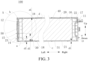
FIG. 3 is a schematic cross-sectional view of the battery according to an embodiment of the present disclosure. -
FIG. 4 is an enlarged view of a portion A inFIG. 3 . -
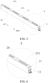
FIG. 5 is a schematic diagram of a battery core assembly according to an embodiment of the present disclosure. -
FIG. 6 is an enlarged view of a portion B inFIG. 5 . -
FIG. 7 is a schematic diagram of the battery core assembly according to an embodiment of the present disclosure. -
FIG. 8 is an enlarged view of a portion C inFIG. 7 . -
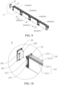
FIG. 9 is a partial three-dimensional schematic exploded view of the battery core assembly according to an embodiment of the present disclosure. -
FIG. 10 is an enlarged view of a portion D inFIG. 9 . -
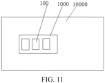
FIG. 11 is a schematic diagram of a vehicle according to an embodiment of the present disclosure. -
-
Vehicle 10000;Battery pack 1000;Battery 100; -
Housing 10;First end plate 11;Second end plate 12;Air suction port 13;Adhesive injection port 14;Air inlet 15;Housing body 16; Accommodatingcavity 17;Outer surface 18; -
Battery core assembly 20;First surface 21;Second surface 22; Sealingmember 23;Third surface 27; -
Battery core unit 24;Subunit 241; First subunit 241a;Second subunit 241b;Battery core 2411;Battery core support 25;Hook 251; - Insulating
member 26;Engagement hole 261;Protective film 28; Throughhole 281;Middle support 29; -
Potting channel 30; pottingadhesive 31; First channel a; Third channel c; -
Air suction channel 40; Second channel b; Fourth channel d; Fifth channel e; -
Gap 50;Conductive sheet 60. - Embodiments of the present disclosure are described in detail below, and the embodiments described with reference to drawings are exemplary. A
battery 100 in an embodiment of the present disclosure is described below with reference toFIG. 1 to FIG. 10 . The battery includes ahousing 10 and abattery core assembly 20. In the description of the present disclosure, a length direction is a left-right direction shown inFIG. 2 , a height direction is an up-down direction shown inFIG. 2 , and a width direction is a front-rear direction shown inFIG. 2 . - As shown in
FIG. 1 to FIG. 9 , thehousing 10 includes ahousing body 16 and afirst end plate 11 and asecond end plate 12 opposite to each other in a length direction of thehousing body 16. Thefirst end plate 11, thesecond end plate 12, and thehousing body 16 define a hermeticaccommodating cavity 17. Anadhesive injection port 14 is formed on thesecond end plate 12. Thebattery core assembly 20 is arranged in theaccommodating cavity 17. Thebattery core assembly 20 includes afirst surface 21. Thefirst surface 21 is opposite to a side of thehousing body 16 in a height direction of thehousing body 16. Agap 50 exists between thesecond end plate 12 and thebattery core assembly 20. A sealingmember 23 is arranged in thegap 50. The sealingmember 23 separates thegap 50 into a first channel a and a second channel b. Theadhesive injection port 14 is in communication with the first channel a. A pottingchannel 30 is provided in thehousing 10. The pottingchannel 30 includes the first channel a and a third channel c located between thefirst surface 21 and an inner wall of thehousing body 16. A pottingadhesive 31 is arranged in thepotting channel 30. - As shown in
FIG. 1 to FIG. 3 , thefirst end plate 11 and thesecond end plate 12 may be respectively located at two ends in the length direction of thebattery core assembly 20. Theadhesive injection port 14 is formed on thesecond end plate 12. Thebattery core assembly 20 is located in theaccommodating cavity 17. Thefirst surface 21 is a surface of thebattery core assembly 20 located below. An inner surface of thesecond end plate 12, the sealingmember 23, and thebattery core assembly 20 jointly define the first channel a. Thefirst surface 21 of thebattery core assembly 20 and an inner surface of a lower portion of thehousing body 16 jointly define the third channel c. Apart of thepotting channel 30 close to a left side and in communication with theadhesive injection port 14 is the first channel a, and a part of thepotting channel 30 opposite thefirst surface 21 is the third channel c. - As shown in
FIG. 2 to FIG. 4 , the sealingmember 23 is arranged between thesecond end plate 12 and thebattery core assembly 20, to seal the gap between thesecond end plate 12 and thebattery core assembly 20. The sealingmember 23 can separate thegap 50 into the first channel a and the second channel b respectively located on an upper side and a lower side. The sealingmember 23 may be made of foam. The sealingmember 23 made of foam has good elasticity and compressibility, which can ensure isolation between the first channel a and the second channel b. For example, when thebattery 100 encounters external factors such as vibration, the sealingmember 23 can absorb the vibration to ensure that a sealing effect is not affected. - According to the
battery 100 in this embodiment of the present disclosure, the pottingchannel 30 and the sealingmember 23 are arranged in thehousing 10, and the sealingmember 23 separates thegap 50, so that the potting adhesive 31 injected through theadhesive injection port 14 can flow to the third channel c through the first channel a, thereby filling thepotting channel 30. In this way, fixing and sealing are realized in thebattery 100, and quick positioning can be realized, which facilitates automatic potting, and improves reliability of an internal structure of thebattery 100. - As shown in
FIG. 3 , anair suction port 13 is formed on thefirst end plate 11. Theair suction port 13 is in communication with the pottingchannel 30, so that pressure in thepotting channel 30 is less than pressure outside thehousing 10. Since two ends of thepotting channel 30 are respectively in communication with theadhesive injection port 14 and theair suction port 13, and the pressure in thepotting channel 30 is less than atmospheric pressure outside thehousing 10, the pottingadhesive 31 may enter thepotting channel 30 through theadhesive injection port 14, and can flow in thepotting channel 30. The pottingadhesive 31 is injected into the pottingchannel 30, so that multiple components in thebattery 100 can be fixed through the pottingadhesive 31 after curing, thereby ensuring structural reliability of thebattery 100. - Vacuumization is performed at the
air suction port 13 to generate negative pressure in thepotting channel 30. Herein, the "negative pressure" is an air pressure state lower than normal pressure. The pottingadhesive 31 is injected into thehousing 10 at theadhesive injection port 14. The potting adhesive 31 can move from an end of thepotting channel 30 in communication with theadhesive injection port 14 to an end of thepotting channel 30 in communication with theair suction port 13 through an adsorption force of the negative pressure, so that the potting adhesive 31 can fill thepotting channel 30. - The
air suction port 13 is formed on thefirst end plate 11, theair suction port 13 is in communication with the pottingchannel 30, and air suction may be performed at theair suction port 13 to reduce the pressure in thepotting channel 30, so that the potting adhesive 31 can smoothly flow into the pottingchannel 30, which not only improves potting efficiency, but also realizes good flow uniformity for thepotting adhesive 31. - Further, as shown in
FIG. 3 , anair inlet 15 spaced apart from theadhesive injection port 14 is further formed on thesecond end plate 12. Theair inlet 15 is in communication with the second channel b. Thebattery core assembly 20 further includes asecond surface 22 opposite thefirst surface 21. Anair suction channel 40 is provided in thehousing 10. Theair suction channel 40 includes the second channel b, a fourth channel d located between thesecond surface 22 and the inner wall of thehousing 10, and a fifth channel e located between thefirst end plate 11 and thebattery core assembly 20. The fifth channel e is in communication with theair suction port 13. - The
air suction channel 40 and thepotting channel 30 are isolated by the sealingmember 23 at thesecond end plate 12, and are spaced apart in a height direction of thebattery 100. Two ends of theair suction channel 40 are respectively in communication with theair inlet 15 and theair suction port 13, to form an airflow circulation channel. - The
air suction channel 40 is provided in thehousing 10, one end of theair suction channel 40 is in communication with theair inlet 15, and the other end is in communication with theair suction port 13. In this way, during the vacuumization at theair suction port 13, since one end of theair suction channel 40 is in communication with the outside through theair inlet 15, air pressure in theair suction channel 40 is greater than air pressure in thepotting channel 30, so that the pottingadhesive 31 of thepotting channel 30 is prevented from partially flowing toward theair suction channel 40, which can reduce use of thepotting adhesive 31, facilitate injection of thepotting adhesive 31, and reduce costs for manufacturing thebattery 100. That theair suction channel 40 is in communication with the outside through theair inlet 15 may be as follows. Theair inlet 15 is not sealed during the vacuumization, and therefore, the air pressure in theair suction channel 40 is equal to the atmospheric pressure, so that the air pressure in theair suction channel 40 is greater than the air pressure in thepotting channel 30. Alternatively, theair inlet 15 may be in communication with an external air supply tank, so that the air pressure in theair suction channel 40 is greater than the air pressure in thepotting channel 30. - In some embodiments, as shown in
FIG. 2 , thefirst surface 21 and thesecond surface 22 are opposite to each other in the height direction. Thefirst end plate 11 and thesecond end plate 12 may be two end plates opposite to each other shown inFIG. 2 in the left-right direction. Thefirst surface 21 and thesecond surface 22 may be two surfaces opposite to each other shown inFIG. 2 andFIG. 5 in the up-down direction. - In addition, as shown in
FIG. 5 to FIG. 8 , thebattery core assembly 20 may further include aprotective film 28. Theprotective film 28 is wrapped on an outer peripheral side of abattery core unit 24, and the left and right ends of theprotective film 28 shown inFIG. 2 are open, so that the left and right ends of thebattery core unit 24 shown inFIG. 2 are exposed. Theprotective film 28 can protect thebattery core unit 24 from external corrosion and protect an outer surface of thebattery core unit 24 from scratches. At least one throughhole 281 is formed on theprotective film 28. The throughhole 281 is provided at least on a side of theprotective film 28 facing the third channel c. By providing the throughhole 281, the potting adhesive 31 can flow to thebattery core unit 24 through the throughhole 281. Theprotective film 28 can not only protect thebattery core assembly 20, but also improve a fixing and mounting effect of thepotting adhesive 31 for thebattery core assembly 20. - The
battery core assembly 20 may include a third surface and a fourth surface (not shown in the figure) opposite to each other in a width direction. At least an outer periphery of the fourth surface and at least an outer periphery of thethird surface 27 are snugly attached to thehousing body 16, which can prevent the potting adhesive 31 from flowing to thethird surface 27 and the fourth surface. During potting, thethird surface 27 and the fourth surface may be arranged to snugly hold thehousing body 16 through pressing or the like without interfering with theair suction channel 40 and thepotting channel 30. In this way, not only is snug attachment between thethird surface 27 and thehousing body 16 ensured, but also isolation between the pottingchannel 30 and theair suction channel 40 is realized, which improves safety performance of thebattery 100. - For example, the
first surface 21 may be constructed from a surface of theprotective film 28 facing a side of the housing body 16 (for example, a lower side shown inFIG. 2 andFIG. 3 ), and thesecond surface 22 may be constructed from a surface of theprotective film 28 facing another other side of the housing body (for example, an upper side shown inFIG. 2 andFIG. 3 ). In other words, thefirst surface 21 and thesecond surface 22 are two surfaces of theprotective film 28 opposite to each other in the height direction of the housing body 16 (or the height direction of the battery 100). Thethird surface 27 may be constructed from a surface of theprotective film 28 facing a side of the housing body 16 (for example, a front side shown inFIG. 2 ), and the fourth surface may be constructed from a surface of theprotective film 28 facing another side of the housing body 16 (for example, a rear side as shown inFIG. 2 ). In other words, thethird surface 27 and the fourth surface are two surfaces of the protective film opposite to each other in the width direction of the housing body 16 (that is, a thickness direction of the battery 100). In this way, flatness of an outer surface of thebattery core assembly 20 can be improved, thereby ensuring snug attachment between thethird surface 27 and thehousing body 16 and between the fourth surface and thehousing body 16. - In some embodiments, the
adhesive injection port 14 and theair suction port 13 are aligned with each other in a length direction of thehousing 10. In this way, the devices can be conveniently arranged at a same height, thereby facilitating a mounting operation of an operator, and improving production efficiency of thebattery 100. - In some embodiments, as shown in
FIG. 3 , a height of thehousing 10 is D1. Thehousing 10 has twoouter surfaces 18 opposite to each other in the height direction. A distance between one of the twoouter surfaces 18 adjacent to thepotting channel 30 and a center of theadhesive injection port 14 is D2. D1 and D2 meet a relationship of 10 mm ≤ D2 ≤ 0.25D1. For example, D1 = 100 mm, and D2 = 20 mm. With reference toFIG. 3 andFIG. 4 , D1 is a height of thehousing 10 in the up-down direction, and D2 is a height between a central axis of theadhesive injection port 14 and a lower surface of the housing 10 (or a lower surface of the housing body 16). The distance between the outer surface of thehousing 10 and the center of theadhesive injection port 14 is controlled, so that not only can thebattery core assembly 20 be mounted to thehousing 10 with internal structure strength being ensured, but also use of the potting adhesive 31 can be reduced, which realizes a proper distance between thehousing 10 and thefirst surface 21, thereby ensuring a potting effect. In addition, a miniaturization design of thebattery 100 can be promoted, and costs can be reduced. - In some embodiments, as shown in
FIG. 3 andFIG. 4 , a distance between one of the twoouter surfaces 18 adjacent to thepotting channel 30 and a center of theair inlet 15 is D3. D2 and D3 meet a relationship of D2 + 18 mm ≤ D3 ≤ D2 + 22 mm. For example, D2 = 20 mm, and D3 = 40 mm. The distance between theouter surface 18 of thehousing 10 and the center of theair inlet 15 is controlled, so that a more proper distance is realized between theair inlet 15 and theadhesive injection port 14 and between theair inlet 15 and thehousing 10, thereby preventing theair inlet 15 from being sealed by the pottingadhesive 31, which can improve use safety of thebattery 100. - In some embodiments, as shown in
FIG. 9 and FIG. 10 , thebattery core assembly 20 includes thebattery core unit 24, abattery core support 25, and an insulatingmember 26. Thebattery core unit 24 includesmultiple subunits 241 arranged in the length direction of thehousing 10 and connected in series. One of themultiple subunits 241 adjacent to thesecond end plate 12 is afirst subunit 241a, and the remainingsubunits 241 may besecond subunits 241b. Thebattery core support 25 is fixed at an end of thefirst subunit 241a facing thesecond end plate 12. The insulatingmember 26 is arranged between thebattery core support 25 and thesecond end plate 12. The sealingmember 23 is sandwiched between thesecond end plate 12 and the insulatingmember 26. - Referring to
FIG. 9 and FIG. 10 , thebattery core assembly 20 includes thebattery core unit 24. For example, thebattery core unit 24 may includemultiple subunits 241. Themultiple subunits 241 may be sequentially arranged in the length direction of thehousing 10 and electrically connected (for example, connected in series). Eachsubunit 241 may includemultiple battery cores 2411 arranged in the width direction and electrically connected (for example, connected in parallel). Thebattery cores 2411 may be soft pack battery cores or bare battery cores. Supports are respectively arranged at both ends in a length direction of eachsubunit 241. The supports are respectively thebattery core support 25 and amiddle support 29. Twomiddle supports 29 are arranged between twoadjacent subunits 241 in thebattery core unit 24. Aconductive sheet 60 is fixed on eachmiddle support 29. Twoadjacent subunits 241 are connected in series through the correspondingconductive sheets 60. Thebattery core assembly 20 may include twobattery core units 24 arranged in the width direction of the housing 10 (that is, the thickness direction of the battery 100). The twobattery core units 24 are connected in series through a connecting sheet arranged on thebattery core support 25. - The insulating
member 26 may be arranged between thebattery core support 25 and thehousing 10. By arranging the insulatingmember 26, thehousing 10 can be insulated from thebattery core unit 24, which improves the safety performance of thebattery 100, and improves reliability and safety of thebattery 100. For example, a side of the insulatingmember 26 facing thebattery core unit 24 is provided with a groove. The groove extends in the height direction of the battery 100 (for example, the up-down direction shown inFIG. 2 ), which can improve a sealing effect of thebattery core unit 24 and facilitate positioning. - In some embodiments, as shown in
FIG. 9 and FIG. 10 , at least onehook 251 is arranged on one of the insulatingmember 26 and thebattery core support 25. At least oneengagement hole 261 is provided on the other of the insulatingmember 26 and thebattery core support 25. Thehook 251 is fitted in theengagement hole 261. For example,multiple engagement holes 261 are provided on a side of the insulatingmember 26 facing thebattery core support 25.Hooks 251 corresponding to the engagement holes 261 are arranged on a side of thebattery core support 25 away from thebattery core unit 24. During assembly between the insulatingmember 26 and thebattery core support 25, thehooks 251 are fitted in engagement holes 261. The fitting between the insulatingmember 26 and thebattery core support 25 through thehook 251 and theengagement hole 261 reduces difficulty in mounting the insulatingmember 26, and facilitates disassembly of the insulatingmember 26 when a quantity ofbattery core units 24 needs to be adjusted. - In some embodiments, as shown in
FIG. 3 , a height of the potting adhesive 31 in the height direction of the housing 10 (the up-down direction shown inFIG. 3 ) is D4. D4 meets 0.8 mm ≤ D4 ≤ 1.5 mm. For example, D4 = 1 mm. Due to resistance in thepotting channel 30, an adhesive layer formed by the pottingadhesive 31 has a varying thickness in the up-down direction of thehousing 10. D4 is a maximum value of the adhesive layer in the height direction, that is, a thickness of the adhesive layer after thepotting channel 30 is completely filled with the pottingadhesive 31. The height of the potting adhesive 31 in the height direction of thehousing 10 is controlled, so that the potting adhesive 31 filled in thepotting channel 30 can ensure structural strength and sealing performance, and use of the potting adhesive 31 can be reduced. - With reference to
FIG. 11 , abattery pack 1000 in an embodiment of a second aspect of the present disclosure includes thebattery 100 in any of the foregoing embodiments. For example, thebattery pack 1000 may include a box body and at least onebattery 100 arranged in the box body. - With reference to
FIG. 11 , avehicle 10000 in an embodiment of a third aspect of the present disclosure includes thebattery pack 1000 in the foregoing embodiment, or includes thebattery 100 in any of the foregoing embodiments. For example, thebattery 100 may not be arranged in the box body, but is directly arranged in a battery accommodating cavity of thevehicle 10000 or the like. - With reference to
FIG. 1 to FIG. 10 , the pottingchannel 30 in communication with theadhesive injection port 14 and theair suction port 13 is provided, so that during the vacuumization at theair suction port 13, the potting adhesive 31 injected through theadhesive injection port 14 can fill thepotting channel 30, which realizes fixing and sealing in thebattery 100, and can realize quick positioning, thereby facilitating automatic potting. In addition, theair suction channel 40 is provided in thehousing 10, one end of theair suction channel 40 is in communication with theair inlet 15, and the other end is in communication with theair suction port 13. In this way, during the vacuumization at theair suction port 13, since one end of theair suction channel 40 is in communication with the outside through theair inlet 15, air pressure in theair suction channel 40 is greater than air pressure in thepotting channel 30, so that the pottingadhesive 31 of thepotting channel 30 is prevented from partially flowing toward theair suction channel 40, which can reduce use of thepotting adhesive 31, facilitate injection of thepotting adhesive 31, and reduce costs for manufacturing thebattery 100. - In the description of the present disclosure, it should be understood that orientation or position relationships indicated by the terms such as "center", "length", "width", "thickness", "up", "down", "front", "rear", "left", "right", "top", "bottom", "inside", "outside", "axial direction", "radial direction", and "circumferential direction" are based on orientation or position relationships shown in the drawings, and are used only for ease and brevity of description of the present disclosure, rather than indicating or implying that the mentioned apparatus or element needs to have a particular orientation or needs to be constructed and operated in a particular orientation. Therefore, such terms should not be construed as a limitation on the present disclosure.
- In the description of the present disclosure, a "first feature" and a "second feature" may include one or more features. In the description of the present disclosure, "multiple" means two or more. In the description of the present disclosure, that the first feature is "over" or "under" the second feature may include that the first feature and the second feature are in direct contact, or may include that the first feature and the second feature are not in direct contact but are in contact by using other features therebetween. In the description of the present disclosure, that the first feature is "over", "above", or "on" the second feature includes that the first feature is directly above or obliquely above the second feature, or merely indicates that the first feature is at a higher horizontal position than the second feature.
- In the description of this specification, descriptions using reference terms "an embodiment", "some embodiments", "an exemplary embodiment", "an example", "a specific example", or "some examples" mean that specific characteristics, structures, materials, or features described with reference to the embodiment or example are included in at least one embodiment or example of the present disclosure. In this specification, exemplary descriptions of the foregoing terms do not necessarily mean the same embodiment or example.
- Although the embodiments of the present disclosure have been shown and described, a person of ordinary skill in the art should understand that various changes, modifications, replacements, and variations may be made to the embodiments without departing from the principle and spirit of the present disclosure, and the scope of the present disclosure is defined by the appended claims and their equivalents.
Claims (13)
- A battery, comprising:a housing, comprising a housing body and a first end plate and a second end plate opposite to each other in a length direction of the housing body, the first end plate, the second end plate, and the housing body defining a hermetic accommodating cavity, and an adhesive injection port being formed on the second end plate; anda battery core assembly, arranged in the accommodating cavity and comprising a first surface, the first surface being opposite to a side of the housing body in a height direction of the housing body, a gap existing between the second end plate and the battery core assembly, a sealing member being arranged in the gap, the sealing member separating the gap into a first channel and a second channel, the adhesive injection port being in communication with the first channel; a potting channel being provided in the housing, the potting channel comprising the first channel and a third channel located between the first surface and an inner wall of the housing body, and a potting adhesive being arranged in the potting channel.
- The battery according to claim 1, wherein an air suction port is formed on the first end plate; and the air suction port is in communication with the potting channel, so that pressure in the potting channel is less than pressure outside the housing.
- The battery according to claim 2, wherein an air inlet spaced apart from the adhesive injection port is further formed on the second end plate; the air inlet is in communication with the second channel; the battery core assembly further comprises a second surface opposite the first surface; an air suction channel is provided in the housing; the air suction channel comprises the second channel, a fourth channel located between the second surface and the inner wall of the housing body, and a fifth channel located between the first end plate and the battery core assembly; and the fifth channel is in communication with the air suction port.
- The battery according to claim 2 or 3, wherein the adhesive injection port and the air suction port are aligned with each other in the length direction of the housing.
- The battery according to any of claims 1 to 4, wherein the battery core assembly comprises a third surface and a fourth surface opposite to each other in a width direction of the housing body; and at least an outer periphery of the fourth surface and at least an outer periphery of the third surface are snugly attached to the housing body.
- The battery according to any of claims 1 to 5, wherein the battery core assembly comprises a battery core unit and a protective film; the protective film is wrapped on an outer peripheral side of the battery core unit; two ends of the protective film in the length direction of the housing body are open; at least one through hole is formed on the protective film; and the through hole is provided at least on a side of the protective film facing the third channel.
- The battery according to any of claims 1 to 6, wherein a height of the housing is D1; the housing has two outer surfaces opposite to each other in the height direction; a distance between one of the two outer surfaces adjacent to the potting channel and a center of the adhesive injection port is D2; and D1 and D2 meet a relationship of 10 mm ≤ D2 ≤ 0.25D1.
- The battery according to claim 7, wherein a distance between one of the two outer surfaces adjacent to the potting channel and a center of the air inlet is D3; and D2 and D3 meet a relationship of D2 + 18 mm ≤ D3 ≤ D2 + 22 mm.
- The battery according to any of claims 1 to 8, wherein the battery core assembly comprises:the battery core unit, comprising a plurality of subunits arranged in the length direction of the housing and connected in series;a battery core support, one of the plurality of subunits adjacent to the second end plate being a first subunit, and the battery core support being fixed at an end of the first subunit facing the second end plate; andan insulating member, arranged between the battery core support and the second end plate, the sealing member being sandwiched between the second end plate and the insulating member.
- The battery according to claim 9, wherein at least one hook is arranged on one of the insulating member and the battery core support; at least one engagement hole is provided on the other of the insulating member and the battery core support; and the hook is fitted in the engagement hole.
- The battery according to any of claims 1 to 10, wherein a height of the potting adhesive in the height direction of the housing is D4, and D4 meets 0.8 mm ≤ D4 ≤ 1.5 mm.
- A battery pack, comprising the battery according to any of claims 1 to 11.
- A vehicle, comprising the battery according to any of claims 1 to 11 or the battery pack according to claim 12.
Applications Claiming Priority (2)
| Application Number | Priority Date | Filing Date | Title |
|---|---|---|---|
| CN202122911541.8U CN217134545U (en) | 2021-11-24 | 2021-11-24 | Battery and vehicle with same |
| PCT/CN2022/132610 WO2023093614A1 (en) | 2021-11-24 | 2022-11-17 | Battery, battery pack, and vehicle |
Publications (2)
| Publication Number | Publication Date |
|---|---|
| EP4401221A1 true EP4401221A1 (en) | 2024-07-17 |
| EP4401221A4 EP4401221A4 (en) | 2025-06-25 |
Family
ID=82617821
Family Applications (1)
| Application Number | Title | Priority Date | Filing Date |
|---|---|---|---|
| EP22897697.3A Pending EP4401221A4 (en) | 2021-11-24 | 2022-11-17 | BATTERY, BATTERY PACK AND VEHICLE |
Country Status (8)
| Country | Link |
|---|---|
| US (1) | US20240234902A1 (en) |
| EP (1) | EP4401221A4 (en) |
| JP (1) | JP7796214B2 (en) |
| KR (1) | KR20240052888A (en) |
| CN (1) | CN217134545U (en) |
| AU (1) | AU2022395738B2 (en) |
| CA (1) | CA3235203A1 (en) |
| WO (1) | WO2023093614A1 (en) |
Families Citing this family (4)
| Publication number | Priority date | Publication date | Assignee | Title |
|---|---|---|---|---|
| CN217134545U (en) * | 2021-11-24 | 2022-08-05 | 比亚迪股份有限公司 | Battery and vehicle with same |
| CN115579574B (en) * | 2022-09-09 | 2023-11-24 | 江苏正力新能电池技术有限公司 | Method and device for encapsulating inner flat layer of explosion-proof valve of battery cell shell and battery cell |
| CN219163546U (en) * | 2022-11-01 | 2023-06-09 | 蜂巢能源科技股份有限公司 | Soft packet of lithium cell module of high protection level |
| CN116937039B (en) * | 2023-09-15 | 2024-01-23 | 宁德时代新能源科技股份有限公司 | Battery pack, method of preparing battery pack, electrical device |
Family Cites Families (9)
| Publication number | Priority date | Publication date | Assignee | Title |
|---|---|---|---|---|
| JP5529164B2 (en) * | 2009-11-17 | 2014-06-25 | 本田技研工業株式会社 | Power storage device |
| JP2012209135A (en) * | 2011-03-30 | 2012-10-25 | Sanyo Electric Co Ltd | Battery pack |
| JP2013243061A (en) * | 2012-05-21 | 2013-12-05 | Nec Energy Devices Ltd | Battery module |
| CN206558567U (en) * | 2016-11-21 | 2017-10-13 | 深圳市沃特玛电池有限公司 | Battery modules |
| DE102019112058B4 (en) * | 2019-05-09 | 2023-07-13 | Dr. Ing. H.C. F. Porsche Aktiengesellschaft | Battery module of a high-voltage battery for an electric vehicle |
| CN210092189U (en) * | 2019-08-15 | 2020-02-18 | 天津市捷威动力工业有限公司 | Soft-package battery module injecting glue structure |
| CN111048868B (en) * | 2019-12-25 | 2022-01-28 | 中国第一汽车股份有限公司 | Battery monomer group and battery module |
| CN211265580U (en) * | 2020-01-21 | 2020-08-14 | 中国第一汽车股份有限公司 | Laminate polymer battery module |
| CN217134545U (en) * | 2021-11-24 | 2022-08-05 | 比亚迪股份有限公司 | Battery and vehicle with same |
-
2021
- 2021-11-24 CN CN202122911541.8U patent/CN217134545U/en active Active
-
2022
- 2022-11-17 JP JP2024518683A patent/JP7796214B2/en active Active
- 2022-11-17 CA CA3235203A patent/CA3235203A1/en active Pending
- 2022-11-17 KR KR1020247012110A patent/KR20240052888A/en active Pending
- 2022-11-17 AU AU2022395738A patent/AU2022395738B2/en active Active
- 2022-11-17 EP EP22897697.3A patent/EP4401221A4/en active Pending
- 2022-11-17 WO PCT/CN2022/132610 patent/WO2023093614A1/en not_active Ceased
-
2024
- 2024-03-26 US US18/617,100 patent/US20240234902A1/en active Pending
Also Published As
| Publication number | Publication date |
|---|---|
| EP4401221A4 (en) | 2025-06-25 |
| CA3235203A1 (en) | 2023-06-01 |
| AU2022395738A1 (en) | 2024-05-02 |
| WO2023093614A1 (en) | 2023-06-01 |
| KR20240052888A (en) | 2024-04-23 |
| AU2022395738B2 (en) | 2026-04-09 |
| CN217134545U (en) | 2022-08-05 |
| JP2024544745A (en) | 2024-12-04 |
| JP7796214B2 (en) | 2026-01-08 |
| US20240234902A1 (en) | 2024-07-11 |
Similar Documents
| Publication | Publication Date | Title |
|---|---|---|
| EP4401221A1 (en) | Battery, battery pack, and vehicle | |
| EP3812632B1 (en) | Explosion-proof valve, battery pack and electric vehicle | |
| CN217158358U (en) | Top cover assembly and single battery | |
| WO2022095195A1 (en) | Circuit board module, machine frame assembly and movable platform | |
| EP4148895A1 (en) | Battery, battery pack and automobile | |
| CN110739422A (en) | Battery cell support group and energy storage device packaging part comprising same | |
| CN220544035U (en) | A battery pack | |
| CN219575778U (en) | Battery cover plate assembly and battery | |
| US11824213B2 (en) | Battery unit, battery module and vehicle | |
| KR102084152B1 (en) | Battery Pack having tray stopper for preventing spring back of Pack cover | |
| CN118398981A (en) | Battery module, electric equipment and glue filling method | |
| CN216287335U (en) | Terminal device | |
| CN223273443U (en) | Shell assembly of battery pack, battery pack and electric equipment | |
| CN220021407U (en) | Battery holders, battery packs and electrical equipment | |
| CN218827494U (en) | Battery cell, battery pack and vehicle | |
| CN224170670U (en) | Pole piece printing fixture based on glue layer lamination | |
| CN209860014U (en) | A battery module cooling device and battery module | |
| CN220358212U (en) | Battery cell packaging structure and battery module | |
| CN224020961U (en) | Battery packs and electrical devices | |
| CN223427683U (en) | Battery packs and electrical equipment | |
| CN219759645U (en) | Battery cell set and battery | |
| CN222980765U (en) | Battery shell, battery and electric equipment | |
| CN223378414U (en) | Battery safety valve and battery | |
| CN116169411A (en) | Battery and vehicle with same | |
| CN221726722U (en) | Screen components and electronic devices |
Legal Events
| Date | Code | Title | Description |
|---|---|---|---|
| STAA | Information on the status of an ep patent application or granted ep patent |
Free format text: STATUS: THE INTERNATIONAL PUBLICATION HAS BEEN MADE |
|
| PUAI | Public reference made under article 153(3) epc to a published international application that has entered the european phase |
Free format text: ORIGINAL CODE: 0009012 |
|
| STAA | Information on the status of an ep patent application or granted ep patent |
Free format text: STATUS: REQUEST FOR EXAMINATION WAS MADE |
|
| 17P | Request for examination filed |
Effective date: 20240410 |
|
| AK | Designated contracting states |
Kind code of ref document: A1 Designated state(s): AL AT BE BG CH CY CZ DE DK EE ES FI FR GB GR HR HU IE IS IT LI LT LU LV MC ME MK MT NL NO PL PT RO RS SE SI SK SM TR |
|
| DAV | Request for validation of the european patent (deleted) | ||
| DAX | Request for extension of the european patent (deleted) | ||
| A4 | Supplementary search report drawn up and despatched |
Effective date: 20250528 |
|
| RIC1 | Information provided on ipc code assigned before grant |
Ipc: H01M 50/24 20210101ALI20250522BHEP Ipc: H01M 50/249 20210101ALI20250522BHEP Ipc: H01M 50/244 20210101AFI20250522BHEP |