EP4401210A1 - Power battery top cover and power battery - Google Patents
Power battery top cover and power battery Download PDFInfo
- Publication number
- EP4401210A1 EP4401210A1 EP22909277.0A EP22909277A EP4401210A1 EP 4401210 A1 EP4401210 A1 EP 4401210A1 EP 22909277 A EP22909277 A EP 22909277A EP 4401210 A1 EP4401210 A1 EP 4401210A1
- Authority
- EP
- European Patent Office
- Prior art keywords
- power battery
- top cover
- battery top
- hole
- upper plastic
- Prior art date
- Legal status (The legal status is an assumption and is not a legal conclusion. Google has not performed a legal analysis and makes no representation as to the accuracy of the status listed.)
- Pending
Links
Images
Classifications
-
- H—ELECTRICITY
- H01—ELECTRIC ELEMENTS
- H01M—PROCESSES OR MEANS, e.g. BATTERIES, FOR THE DIRECT CONVERSION OF CHEMICAL ENERGY INTO ELECTRICAL ENERGY
- H01M10/00—Secondary cells; Manufacture thereof
- H01M10/04—Construction or manufacture in general
-
- H—ELECTRICITY
- H01—ELECTRIC ELEMENTS
- H01M—PROCESSES OR MEANS, e.g. BATTERIES, FOR THE DIRECT CONVERSION OF CHEMICAL ENERGY INTO ELECTRICAL ENERGY
- H01M50/00—Constructional details or processes of manufacture of the non-active parts of electrochemical cells other than fuel cells, e.g. hybrid cells
- H01M50/10—Primary casings; Jackets or wrappings
- H01M50/102—Primary casings; Jackets or wrappings characterised by their shape or physical structure
- H01M50/103—Primary casings; Jackets or wrappings characterised by their shape or physical structure prismatic or rectangular
-
- H—ELECTRICITY
- H01—ELECTRIC ELEMENTS
- H01M—PROCESSES OR MEANS, e.g. BATTERIES, FOR THE DIRECT CONVERSION OF CHEMICAL ENERGY INTO ELECTRICAL ENERGY
- H01M50/00—Constructional details or processes of manufacture of the non-active parts of electrochemical cells other than fuel cells, e.g. hybrid cells
- H01M50/10—Primary casings; Jackets or wrappings
- H01M50/147—Lids or covers
-
- H—ELECTRICITY
- H01—ELECTRIC ELEMENTS
- H01M—PROCESSES OR MEANS, e.g. BATTERIES, FOR THE DIRECT CONVERSION OF CHEMICAL ENERGY INTO ELECTRICAL ENERGY
- H01M50/00—Constructional details or processes of manufacture of the non-active parts of electrochemical cells other than fuel cells, e.g. hybrid cells
- H01M50/10—Primary casings; Jackets or wrappings
- H01M50/147—Lids or covers
- H01M50/148—Lids or covers characterised by their shape
-
- H—ELECTRICITY
- H01—ELECTRIC ELEMENTS
- H01M—PROCESSES OR MEANS, e.g. BATTERIES, FOR THE DIRECT CONVERSION OF CHEMICAL ENERGY INTO ELECTRICAL ENERGY
- H01M50/00—Constructional details or processes of manufacture of the non-active parts of electrochemical cells other than fuel cells, e.g. hybrid cells
- H01M50/10—Primary casings; Jackets or wrappings
- H01M50/147—Lids or covers
- H01M50/148—Lids or covers characterised by their shape
- H01M50/15—Lids or covers characterised by their shape for prismatic or rectangular cells
-
- H—ELECTRICITY
- H01—ELECTRIC ELEMENTS
- H01M—PROCESSES OR MEANS, e.g. BATTERIES, FOR THE DIRECT CONVERSION OF CHEMICAL ENERGY INTO ELECTRICAL ENERGY
- H01M50/00—Constructional details or processes of manufacture of the non-active parts of electrochemical cells other than fuel cells, e.g. hybrid cells
- H01M50/10—Primary casings; Jackets or wrappings
- H01M50/183—Sealing members
- H01M50/184—Sealing members characterised by their shape or structure
-
- H—ELECTRICITY
- H01—ELECTRIC ELEMENTS
- H01M—PROCESSES OR MEANS, e.g. BATTERIES, FOR THE DIRECT CONVERSION OF CHEMICAL ENERGY INTO ELECTRICAL ENERGY
- H01M50/00—Constructional details or processes of manufacture of the non-active parts of electrochemical cells other than fuel cells, e.g. hybrid cells
- H01M50/10—Primary casings; Jackets or wrappings
- H01M50/183—Sealing members
- H01M50/186—Sealing members characterised by the disposition of the sealing members
- H01M50/188—Sealing members characterised by the disposition of the sealing members the sealing members being arranged between the lid and terminal
-
- H—ELECTRICITY
- H01—ELECTRIC ELEMENTS
- H01M—PROCESSES OR MEANS, e.g. BATTERIES, FOR THE DIRECT CONVERSION OF CHEMICAL ENERGY INTO ELECTRICAL ENERGY
- H01M50/00—Constructional details or processes of manufacture of the non-active parts of electrochemical cells other than fuel cells, e.g. hybrid cells
- H01M50/30—Arrangements for facilitating escape of gases
-
- H—ELECTRICITY
- H01—ELECTRIC ELEMENTS
- H01M—PROCESSES OR MEANS, e.g. BATTERIES, FOR THE DIRECT CONVERSION OF CHEMICAL ENERGY INTO ELECTRICAL ENERGY
- H01M50/00—Constructional details or processes of manufacture of the non-active parts of electrochemical cells other than fuel cells, e.g. hybrid cells
- H01M50/30—Arrangements for facilitating escape of gases
- H01M50/342—Non-re-sealable arrangements
-
- H—ELECTRICITY
- H01—ELECTRIC ELEMENTS
- H01M—PROCESSES OR MEANS, e.g. BATTERIES, FOR THE DIRECT CONVERSION OF CHEMICAL ENERGY INTO ELECTRICAL ENERGY
- H01M50/00—Constructional details or processes of manufacture of the non-active parts of electrochemical cells other than fuel cells, e.g. hybrid cells
- H01M50/50—Current conducting connections for cells or batteries
- H01M50/543—Terminals
- H01M50/547—Terminals characterised by the disposition of the terminals on the cells
- H01M50/55—Terminals characterised by the disposition of the terminals on the cells on the same side of the cell
-
- H—ELECTRICITY
- H01—ELECTRIC ELEMENTS
- H01M—PROCESSES OR MEANS, e.g. BATTERIES, FOR THE DIRECT CONVERSION OF CHEMICAL ENERGY INTO ELECTRICAL ENERGY
- H01M50/00—Constructional details or processes of manufacture of the non-active parts of electrochemical cells other than fuel cells, e.g. hybrid cells
- H01M50/50—Current conducting connections for cells or batteries
- H01M50/543—Terminals
- H01M50/552—Terminals characterised by their shape
- H01M50/553—Terminals adapted for prismatic, pouch or rectangular cells
- H01M50/557—Plate-shaped terminals
-
- H—ELECTRICITY
- H01—ELECTRIC ELEMENTS
- H01M—PROCESSES OR MEANS, e.g. BATTERIES, FOR THE DIRECT CONVERSION OF CHEMICAL ENERGY INTO ELECTRICAL ENERGY
- H01M50/00—Constructional details or processes of manufacture of the non-active parts of electrochemical cells other than fuel cells, e.g. hybrid cells
- H01M50/50—Current conducting connections for cells or batteries
- H01M50/543—Terminals
- H01M50/564—Terminals characterised by their manufacturing process
- H01M50/567—Terminals characterised by their manufacturing process by fixing means, e.g. screws, rivets or bolts
-
- Y—GENERAL TAGGING OF NEW TECHNOLOGICAL DEVELOPMENTS; GENERAL TAGGING OF CROSS-SECTIONAL TECHNOLOGIES SPANNING OVER SEVERAL SECTIONS OF THE IPC; TECHNICAL SUBJECTS COVERED BY FORMER USPC CROSS-REFERENCE ART COLLECTIONS [XRACs] AND DIGESTS
- Y02—TECHNOLOGIES OR APPLICATIONS FOR MITIGATION OR ADAPTATION AGAINST CLIMATE CHANGE
- Y02E—REDUCTION OF GREENHOUSE GAS [GHG] EMISSIONS, RELATED TO ENERGY GENERATION, TRANSMISSION OR DISTRIBUTION
- Y02E60/00—Enabling technologies; Technologies with a potential or indirect contribution to GHG emissions mitigation
- Y02E60/10—Energy storage using batteries
Definitions
- the present disclosure relates to the field of power battery technologies, for example, relates to a power battery top cover and a power battery.
- Green transportation has become a major trend for countries to develop energy conservation and emission reduction.
- electric vehicles have been an increasingly attention from governments, enterprises, and the public, with advantages such as energy conservation, environmental protection, and clean energy compared to traditional fuel vehicles, and thus the costs on environment and economics are reduced. Therefore, power batteries and new energy vehicle related industries are vigorously developed in our place.
- a power battery is used as a core energy storage component of an electric vehicle, and sealing performance of the power battery directly affects a safety factor of the electric vehicle.
- Sealing performance of a power battery top cover of the power battery is a key to determine the sealing performance of the power battery. In a case that the power battery top cover is failed, it leads to a leakage in a core pack in the power battery, decreased energy storage performance, or even lead to danger such as short circuit, fire, and explosion of the core pack.
- the sealing performance of the power battery top cover in related technologies mainly relies on a compression by a pole post or a pole plate on a sealing ring. These structures are substantially formed by riveting or integrated injection molding, and the contact between an upper plastic part and an aluminum plate is tight. As a result, in a case that the sealing ring is failed, the sealing performance of the power battery top cover cannot be detected effectively and quickly, thereby affecting safety performance of the core pack.
- the present disclosure provides a power battery top cover, which has a simple structure and is easy to produce.
- an external detection tool can be used to detect the failed sealing ring in time, thereby improving safety performance of the power battery top cover and increasing a product yield.
- the present disclosure provides a power battery top cover, including:
- the present disclosure further provides a power battery, which has strong safety performance and can improve work efficiency. Therefore, a risk of leakage from the core pack or even explosion of the power battery can be avoided.
- the present disclosure provides a power battery, including:
- connection may be a fixed connection, a detachable connection, or an integral connection; or the connection may be a mechanical connection or an electrical connection; or the connection may be a direct connection, an indirect connection through an intermediate, or internal communication between two elements or an interaction relationship between two elements.
- connection may be a fixed connection, a detachable connection, or an integral connection; or the connection may be a mechanical connection or an electrical connection; or the connection may be a direct connection, an indirect connection through an intermediate, or internal communication between two elements or an interaction relationship between two elements.
- a first feature is “on” or “below” a second feature may indicate that the first feature and the second feature are in direct contact, or the first feature and the second feature are in contact through additional features between them rather than in direct contact.
- the first feature is “above”, “over”, or “on” the second feature may indicate that the first feature is directly above and obliquely above the second feature, or may merely indicate that the horizontal position of the first feature is higher than that of the second feature.
- That the first feature is “below”, “under”, or “beneath” the second may indicate that the first feature is directly below and obliquely below the second feature, or may merely indicate that the horizontal height of the first feature is lower than that of the second feature.
- orientation or position relationships indicated by terms such as “upper”, “lower”, “left”, and “right” are based on orientation or position relationships shown in the accompanying drawings, and are used only for ease of description and simplifying operations, rather than indicating or implying that the mentioned apparatus or element has a particular orientation or is constructed and operated in a particular orientation.
- first and second are only used to distinguish from descriptions and have no specific meaning.
- the present embodiment provides a power battery top cover 100.
- the power battery top cover 100 is configured to be connected to a casing in which a core pack is mounted.
- the power battery top cover 100 mainly includes a cover plate 1, an upper plastic part 2, a sealing ring 3, and a pole post 4.
- the cover plate 1 is provided with a first through-hole 11 and a first groove 12.
- the upper plastic part 2 is provided with a second through-hole 23.
- the upper plastic part 2 is embedded in the first groove 12, and a vent portion 21 is defined between a lower surface of the upper plastic part 2 and the first groove 12.
- the sealing ring 3 is partially embedded in the first through-hole 11.
- the pole post 4 partially extends through the first through-hole 11 and the second through-hole 23, and is in an interference fit with the sealing ring 3 and the upper plastic part 2.
- the cover plate 1 may be made of lightweight aluminum metal material.
- pole posts 4 may be provided, one is a positive pole post and the other is a negative pole post, to facilitate charging and discharging a power battery.
- the pole post 4 may alternatively be made of aluminum metal material or copper metal material, and details are not described herein again.
- the power battery top cover 100 in the present embodiment has a simple structure and is easy to produce.
- the airflow can pass through the vent portion 21 from one side of the cover plate 1 and then flow to the other side of the cover plate 1.
- the external detection tool can detect a failed sealing ring 3 in time, thereby increasing the product yield of the power battery top cover 100 and improving the reliability and safety of the power battery top cover 100.
- an upper plastic part vent hole 211 may be integrally injected and molded on the upper plastic part 2 by the operator.
- the upper plastic part vent hole 211 is the vent portion 21. Therefore, in a case that the sealing ring 3 is failed, the gas in the lower surface area of the cover plate 1 can pass through the failed sealing ring 3 and flow through the upper plastic part vent hole 211, and then flow to an upper surface area of the cover plate 1.
- the operator can use the external detection tool to detect unqualification of the sealing ring 3 of the power battery top cover 100, to rework the unqualified sealing ring in time. In this way, the power battery top cover 100 with poor sealing performance is prevented from going to subsequent manufacturing processes and affecting the reliability and safety of the power battery top cover 100. Therefore, production efficiency and the safety performance of the power battery top cover 100 are improved.
- the vent portion 21 is provided around an axis of the upper plastic part 2. In this way, the stability of the upper plastic part 2 during mounting can be improved and the upper plastic part 2 is more evenly stressed. In a case that the sealing ring 3 is failed, the gas in the lower surface area of the cover plate 1 can flow out of the vent portion 21 in time, thereby improving work efficiency of the operator in detecting the unqualification of the sealing ring 3.
- the operator may alternatively provide the vent portion 21 at another position on the upper plastic part 2 according to an actual situation, as long as it can be ensured that when the sealing ring 3 is failed, the gas in the lower surface area of the cover plate 1 can flow out of the vent portion 21 in time.
- the sealing ring 3 includes a first boss 31.
- the first boss 31 is arranged between the lower surface of the cover plate 1 and the pole post 4.
- a length of the first boss 31 is greater than a length of the first through-hole 11 in a radial direction (an X-axis direction) of the first through-hole.
- the sealing ring 3 can be prevented from slipping out of the first through-hole 11 when the pole post 4 is riveted to the cover plate 1.
- an end of the pole post 4 close to the first boss 31 is provided with a second boss 41.
- a length of the second boss 41 is greater than the length of the first boss 31 in the X-axis direction. In this way, as the pole post 4 is riveted to the cover plate 1, the second boss 41 can compress the first boss 31, thereby enabling the first boss 31 to be embedded between the cover plate 1 and the second boss 41. Therefore, the sealing performance of the sealing ring 3 on the cover plate 1 and the pole post 4 is improved.
- the first boss 31, the second boss 41, and the first through-hole 11 may have a circular shape, which facilitates improving the stability and reliability of the power battery top cover 100.
- the operator may alternatively set the first boss 31, the second boss 41, and the first through-hole 11 to another shape according to an actual situation, as long as the sealing performance on the power battery top cover 100 can be ensured.
- the power battery top cover 100 further includes a pole plate 5 riveted to the pole post 4.
- the pole plate 5 is arranged to protect the upper plastic part 2.
- the pole plate 5 is riveted to the pole post 4 to improve the strength and stability of the pole post 4.
- the pole plate 5 is provided with a second groove 51
- the upper plastic part 2 is provided with a protrusion 22, and the protrusion 22 is in an interference fit with the second groove 51. In this way, as the protrusion 22 is in an interference fit with the second groove 51, the stability and reliability of a connection between the upper plastic part 2 and the pole plate 5 can be improved. Therefore, a risk of displacement or detachment of the pole plate 5 from the upper plastic part 2 during a normal operation of the power battery cover plate 1 can be avoided.
- the cover plate 1 may be further provided with an explosion-proof valve 6 and a liquid injection hole 7.
- the explosion-proof valve 6 is embedded in the cover plate 1.
- the explosion-proof valve 6 can burst open to release the pressure in the power battery. In this way, the power battery top cover 100 is protected, and the power battery is prevented from exploding due to the excessively large pressure inside.
- the liquid injection hole 7 is configured for injection of electrolytic solution into the power battery.
- a power battery is provided in the present embodiment.
- the power battery includes a casing 200, a core pack 300, and the power battery top cover 100.
- the casing 200 is provided with an opening
- the core pack 300 is mounted inside the casing 200
- the power battery top cover 100 covers the opening.
- a size and shape of the power battery top cover 100 fits a size and shape of the opening on the casing 200. Therefore, the stability and reliability of a connection between the power battery top cover 100 and the casing 200 can be ensured.
- gas generated by the core pack 300 can pass through the failed sealing ring 3 and flow to the upper plastic part vent hole 211, and then flow out of the cover plate 1.
- the operator can use an external detection tool or equipment to detect the power battery with the failed sealing ring 3 in time, and then maintain the power battery or replace the power battery with a new power battery in time. In this way, work efficiency and the safety performance of the power battery can be improved.
- the power battery provided in the present disclosure has high safety performance.
- the operator can detect the power battery with the failed sealing ring in time, and then maintain the power battery or replace the power battery with a new power battery in time. In this way, work efficiency and the safety performance of the power battery can be improved, thereby avoiding the risk of core pack leakage or even explosion of the power battery.
- the present embodiment provides a power battery top cover 100.
- the power battery top cover 100 in the present embodiment is provided with a plurality of cover plate vent holes 212.
- Each of the cover plate vent holes 212 is formed by punching.
- the cover plate vent hole 212 is the vent portion 21 of Embodiment 1. Therefore, in a case that the sealing ring 3 is failed, the gas in the lower surface area of the cover plate 1 can pass through the failed sealing ring 3 and flow through the cover plate vent hole 212, and then flow to the upper surface area of the cover plate 1.
- the operator can use the external detection tool to detect the unqualification of the sealing ring 3 of the power battery top cover 100 and rework the unqualified sealing ring in time. In this way, the power battery top cover 100 with poor sealing performance is prevented from going to subsequent manufacturing processes and affecting the reliability and safety of the power battery top cover 100. Therefore, production efficiency and the safety performance of the power battery top cover 100 are improved.
- the vent portion 21 is provided around an axis of the cover plate 1 along the X-axis. In this way, the stability of the cover plate 1 during mounting can be improved and the cover plate 1 is more evenly stressed. In a case that the sealing ring 3 is failed, the gas in the lower surface area of the cover plate 1 can flow out of the vent portion 21 in time, thereby improving work efficiency of the operator in detecting the unqualification of the sealing ring 3.
- the operator may alternatively provide the vent portion 21 at another position on the cover plate 1 according to an actual situation, as long as it can be ensured that when the sealing ring 3 is failed, the gas in the lower surface area of the cover plate 1 can flow out of the vent portion 21 in time.
- the operator may use methods such as cutting and drilling to form the cover plate vent hole 212.
- the remaining structures of the present embodiment are the same as those of Embodiment 1, and details are not described herein again.
- the present embodiment provides a power battery.
- the power battery includes a casing 200, a core pack 300, and the power battery top cover 100.
- the casing 200 is provided with an opening
- the core pack 300 is mounted inside the casing 200
- the power battery top cover 100 covers the opening.
- a size and shape of the power battery top cover 100 fits a size and shape of the opening on the casing 200. Therefore, the stability and reliability of a connection between the power battery top cover 100 and the casing 200 can be ensured.
- gas generated by the core pack 300 can pass through the failed sealing ring 3 and flow through the cover plate vent hole 212, and then flow out of the cover plate 1.
- the operator can use an external detection tool or equipment to detect the power battery with the failed sealing ring 3 in time, and then maintain the power battery or replace the power battery with a new power battery in time. In this way, work efficiency and the safety performance of the power battery can be improved, thereby avoiding the risk of core pack 300 leakage or even explosion of the power battery.
Landscapes
- Chemical & Material Sciences (AREA)
- Chemical Kinetics & Catalysis (AREA)
- Electrochemistry (AREA)
- General Chemical & Material Sciences (AREA)
- Engineering & Computer Science (AREA)
- Manufacturing & Machinery (AREA)
- Gas Exhaust Devices For Batteries (AREA)
- Battery Mounting, Suspending (AREA)
Abstract
Description
- The present disclosure claims priority to
Chinese Patent Application No. 202123244603.0, filed with the China National Intellectual Property Administration on December 22, 2021 - The present disclosure relates to the field of power battery technologies, for example, relates to a power battery top cover and a power battery.
- As environmental issues and energy crises are increasingly serious, the world is devoted to energy conservation and emission reduction. Green transportation has become a major trend for countries to develop energy conservation and emission reduction. As a representative of green transportation, electric vehicles have been an increasingly attention from governments, enterprises, and the public, with advantages such as energy conservation, environmental protection, and clean energy compared to traditional fuel vehicles, and thus the costs on environment and economics are reduced. Therefore, power batteries and new energy vehicle related industries are vigorously developed in our place.
- A power battery is used as a core energy storage component of an electric vehicle, and sealing performance of the power battery directly affects a safety factor of the electric vehicle. Sealing performance of a power battery top cover of the power battery is a key to determine the sealing performance of the power battery. In a case that the power battery top cover is failed, it leads to a leakage in a core pack in the power battery, decreased energy storage performance, or even lead to danger such as short circuit, fire, and explosion of the core pack. The sealing performance of the power battery top cover in related technologies mainly relies on a compression by a pole post or a pole plate on a sealing ring. These structures are substantially formed by riveting or integrated injection molding, and the contact between an upper plastic part and an aluminum plate is tight. As a result, in a case that the sealing ring is failed, the sealing performance of the power battery top cover cannot be detected effectively and quickly, thereby affecting safety performance of the core pack.
- The present disclosure provides a power battery top cover, which has a simple structure and is easy to produce. In a case that a sealing ring is failed, an external detection tool can be used to detect the failed sealing ring in time, thereby improving safety performance of the power battery top cover and increasing a product yield.
- The present disclosure provides a power battery top cover, including:
- a cover plate provided with a first through-hole and a first groove;
- an upper plastic part provided with a second through-hole, wherein the upper plastic part is embedded in the first groove, and a vent portion is defined between a lower surface of the upper plastic part and the first groove;
- a sealing ring partially embedded in the first through-hole; and
- a pole post partially extended through the first through-hole and the second through-hole, wherein the pole post is in an interference fit with the sealing ring and the upper plastic part.
- The present disclosure further provides a power battery, which has strong safety performance and can improve work efficiency. Therefore, a risk of leakage from the core pack or even explosion of the power battery can be avoided.
- The present disclosure provides a power battery, including:
- a casing provided with an opening;
- a core pack mounted in the casing; and
- the power battery top cover as mentioned above, wherein the power battery top cover covers the opening.
-
-
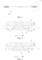
FIG. 1 is a cross-sectional view of a power battery top cover according to some embodiments of the present disclosure. -
FIG. 2 is a partial enlarged view of A inFIG. 1 . -
FIG. 3 is a partial enlarged view of A inFIG. 1 . -
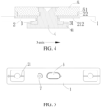
FIG. 4 is a partial enlarged view of A inFIG. 1 . -
FIG. 5 is a top view of a power battery top cover according to some embodiments of the present disclosure. -
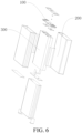
FIG. 6 is an exploded view of a power battery according to some embodiments of the present disclosure. -
- 100. Power battery top cover;
- 1. Cover plate; 11. First through-hole; 12. First groove;
- 2. Upper plastic part; 21. Vent portion; 22. Protrusion; 23. Second through-hole; 211. Upper plastic part vent hole; 212. Cover plate vent hole;
- 3. Sealing ring; 31. First boss; 4. Pole post; 41. Second boss;
- 5. Pole plate; 51. Second groove; 6. Explosion-proof valve; 7. Liquid injection hole;
- 200. Casing; 300. Core pack.
- The technical solution of the present disclosure is explained below with reference to the accompanying drawings and embodiments.
- In the description of the present disclosure, terms "linked", "connected", and "fixed" should be understood in a broad sense. For example, the connection may be a fixed connection, a detachable connection, or an integral connection; or the connection may be a mechanical connection or an electrical connection; or the connection may be a direct connection, an indirect connection through an intermediate, or internal communication between two elements or an interaction relationship between two elements. A person of ordinary skill in the art may understand the meanings of the foregoing terms in the present disclosure according to an actual situation.
- In the present disclosure, a first feature is "on" or "below" a second feature may indicate that the first feature and the second feature are in direct contact, or the first feature and the second feature are in contact through additional features between them rather than in direct contact. In addition, that the first feature is "above", "over", or "on" the second feature may indicate that the first feature is directly above and obliquely above the second feature, or may merely indicate that the horizontal position of the first feature is higher than that of the second feature. That the first feature is "below", "under", or "beneath" the second may indicate that the first feature is directly below and obliquely below the second feature, or may merely indicate that the horizontal height of the first feature is lower than that of the second feature.
- In the description of the present embodiment, orientation or position relationships indicated by terms such as "upper", "lower", "left", and "right" are based on orientation or position relationships shown in the accompanying drawings, and are used only for ease of description and simplifying operations, rather than indicating or implying that the mentioned apparatus or element has a particular orientation or is constructed and operated in a particular orientation. In addition, the terms "first" and "second" are only used to distinguish from descriptions and have no specific meaning.
- As shown in
FIGs. 1 and 2 , the present embodiment provides a powerbattery top cover 100. The powerbattery top cover 100 is configured to be connected to a casing in which a core pack is mounted. The powerbattery top cover 100 mainly includes acover plate 1, an upperplastic part 2, a sealingring 3, and apole post 4. Thecover plate 1 is provided with a first through-hole 11 and afirst groove 12. The upperplastic part 2 is provided with a second through-hole 23. The upperplastic part 2 is embedded in thefirst groove 12, and avent portion 21 is defined between a lower surface of the upperplastic part 2 and thefirst groove 12. The sealingring 3 is partially embedded in the first through-hole 11. Thepole post 4 partially extends through the first through-hole 11 and the second through-hole 23, and is in an interference fit with the sealingring 3 and the upperplastic part 2. - Based on the above structures, during actual manufacturing of the power
battery top cover 100, in a case that the sealingring 3 is failed, gas in a lower surface area of thecover plate 1 can pass through the failed sealingring 3 and flow through thevent portion 21. Then, an operator can use an external detection tool or equipment to detect an airflow in time, and can determine that the powerbattery top cover 100 is unqualified. In this way, the powerbattery top cover 100 with poor sealing performance is prevented from going to subsequent manufacturing processes, thereby increasing a product yield of the powerbattery top cover 100 and improving the reliability and safety of the powerbattery top cover 100. Therefore, production efficiency is improved. Thecover plate 1 may be made of lightweight aluminum metal material. Twopole posts 4 may be provided, one is a positive pole post and the other is a negative pole post, to facilitate charging and discharging a power battery. In addition, thepole post 4 may alternatively be made of aluminum metal material or copper metal material, and details are not described herein again. - Compared with related technologies, the power
battery top cover 100 in the present embodiment has a simple structure and is easy to produce. By defining thevent portion 21 between the upperplastic part 2 and thecover plate 1, the airflow can pass through thevent portion 21 from one side of thecover plate 1 and then flow to the other side of thecover plate 1. In this way, the external detection tool can detect a failed sealingring 3 in time, thereby increasing the product yield of the powerbattery top cover 100 and improving the reliability and safety of the powerbattery top cover 100. - As shown in
FIG. 3 , for example, an upper plasticpart vent hole 211 may be integrally injected and molded on the upperplastic part 2 by the operator. The upper plasticpart vent hole 211 is thevent portion 21. Therefore, in a case that the sealingring 3 is failed, the gas in the lower surface area of thecover plate 1 can pass through the failed sealingring 3 and flow through the upper plasticpart vent hole 211, and then flow to an upper surface area of thecover plate 1. The operator can use the external detection tool to detect unqualification of the sealingring 3 of the powerbattery top cover 100, to rework the unqualified sealing ring in time. In this way, the powerbattery top cover 100 with poor sealing performance is prevented from going to subsequent manufacturing processes and affecting the reliability and safety of the powerbattery top cover 100. Therefore, production efficiency and the safety performance of the powerbattery top cover 100 are improved. - In the present embodiment, the
vent portion 21 is provided around an axis of the upperplastic part 2. In this way, the stability of the upperplastic part 2 during mounting can be improved and the upperplastic part 2 is more evenly stressed. In a case that the sealingring 3 is failed, the gas in the lower surface area of thecover plate 1 can flow out of thevent portion 21 in time, thereby improving work efficiency of the operator in detecting the unqualification of the sealingring 3. In another embodiment of the present disclosure, the operator may alternatively provide thevent portion 21 at another position on the upperplastic part 2 according to an actual situation, as long as it can be ensured that when the sealingring 3 is failed, the gas in the lower surface area of thecover plate 1 can flow out of thevent portion 21 in time. - As shown in
FIGs. 1 and 2 , in the present embodiment, the sealingring 3 includes afirst boss 31. Thefirst boss 31 is arranged between the lower surface of thecover plate 1 and thepole post 4. A length of thefirst boss 31 is greater than a length of the first through-hole 11 in a radial direction (an X-axis direction) of the first through-hole. In this way, the reliability and stability of a connection between the sealingring 3 and thecover plate 1 can be enhanced. The sealingring 3 can be prevented from slipping out of the first through-hole 11 when thepole post 4 is riveted to thecover plate 1. In addition, an end of thepole post 4 close to thefirst boss 31 is provided with asecond boss 41. A length of thesecond boss 41 is greater than the length of thefirst boss 31 in the X-axis direction. In this way, as thepole post 4 is riveted to thecover plate 1, thesecond boss 41 can compress thefirst boss 31, thereby enabling thefirst boss 31 to be embedded between thecover plate 1 and thesecond boss 41. Therefore, the sealing performance of the sealingring 3 on thecover plate 1 and thepole post 4 is improved. - In another embodiment of the present disclosure, the
first boss 31, thesecond boss 41, and the first through-hole 11 may have a circular shape, which facilitates improving the stability and reliability of the powerbattery top cover 100. The operator may alternatively set thefirst boss 31, thesecond boss 41, and the first through-hole 11 to another shape according to an actual situation, as long as the sealing performance on the powerbattery top cover 100 can be ensured. - As shown in
FIGs. 1 and 2 , in the present embodiment, the powerbattery top cover 100 further includes apole plate 5 riveted to thepole post 4. On one hand, thepole plate 5 is arranged to protect the upperplastic part 2. On the other hand, thepole plate 5 is riveted to thepole post 4 to improve the strength and stability of thepole post 4. Optionally, in the present embodiment, thepole plate 5 is provided with asecond groove 51, the upperplastic part 2 is provided with aprotrusion 22, and theprotrusion 22 is in an interference fit with thesecond groove 51. In this way, as theprotrusion 22 is in an interference fit with thesecond groove 51, the stability and reliability of a connection between the upperplastic part 2 and thepole plate 5 can be improved. Therefore, a risk of displacement or detachment of thepole plate 5 from the upperplastic part 2 during a normal operation of the powerbattery cover plate 1 can be avoided. - As shown in
FIG. 5 , in the present embodiment, thecover plate 1 may be further provided with an explosion-proof valve 6 and aliquid injection hole 7. The explosion-proof valve 6 is embedded in thecover plate 1. In a case that the heat from thermal runaway is concentrated in the power battery, or the air pressure is increased in the power battery, the explosion-proof valve 6 can burst open to release the pressure in the power battery. In this way, the powerbattery top cover 100 is protected, and the power battery is prevented from exploding due to the excessively large pressure inside. Theliquid injection hole 7 is configured for injection of electrolytic solution into the power battery. - As shown in
FIG. 6 , a power battery is provided in the present embodiment. The power battery includes acasing 200, acore pack 300, and the powerbattery top cover 100. Thecasing 200 is provided with an opening, thecore pack 300 is mounted inside thecasing 200, and the powerbattery top cover 100 covers the opening. A size and shape of the powerbattery top cover 100 fits a size and shape of the opening on thecasing 200. Therefore, the stability and reliability of a connection between the powerbattery top cover 100 and thecasing 200 can be ensured. In a case that the sealingring 3 on the powerbattery top cover 100 is failed, gas generated by thecore pack 300 can pass through the failed sealingring 3 and flow to the upper plasticpart vent hole 211, and then flow out of thecover plate 1. The operator can use an external detection tool or equipment to detect the power battery with the failed sealingring 3 in time, and then maintain the power battery or replace the power battery with a new power battery in time. In this way, work efficiency and the safety performance of the power battery can be improved. - The power battery provided in the present disclosure has high safety performance. In a case that the sealing ring is failed, the operator can detect the power battery with the failed sealing ring in time, and then maintain the power battery or replace the power battery with a new power battery in time. In this way, work efficiency and the safety performance of the power battery can be improved, thereby avoiding the risk of core pack leakage or even explosion of the power battery.
- The present embodiment provides a power
battery top cover 100. As shown inFIG. 4 , the powerbattery top cover 100 in the present embodiment is provided with a plurality of cover plate vent holes 212. Each of the cover plate vent holes 212 is formed by punching. The coverplate vent hole 212 is thevent portion 21 ofEmbodiment 1. Therefore, in a case that the sealingring 3 is failed, the gas in the lower surface area of thecover plate 1 can pass through the failed sealingring 3 and flow through the coverplate vent hole 212, and then flow to the upper surface area of thecover plate 1. The operator can use the external detection tool to detect the unqualification of the sealingring 3 of the powerbattery top cover 100 and rework the unqualified sealing ring in time. In this way, the powerbattery top cover 100 with poor sealing performance is prevented from going to subsequent manufacturing processes and affecting the reliability and safety of the powerbattery top cover 100. Therefore, production efficiency and the safety performance of the powerbattery top cover 100 are improved. - In the present embodiment, the
vent portion 21 is provided around an axis of thecover plate 1 along the X-axis. In this way, the stability of thecover plate 1 during mounting can be improved and thecover plate 1 is more evenly stressed. In a case that the sealingring 3 is failed, the gas in the lower surface area of thecover plate 1 can flow out of thevent portion 21 in time, thereby improving work efficiency of the operator in detecting the unqualification of the sealingring 3. In another embodiment of the present disclosure, the operator may alternatively provide thevent portion 21 at another position on thecover plate 1 according to an actual situation, as long as it can be ensured that when the sealingring 3 is failed, the gas in the lower surface area of thecover plate 1 can flow out of thevent portion 21 in time. - In addition to punching, the operator may use methods such as cutting and drilling to form the cover
plate vent hole 212. The remaining structures of the present embodiment are the same as those ofEmbodiment 1, and details are not described herein again. - The present embodiment provides a power battery. As shown in
FIG. 6 , the power battery includes acasing 200, acore pack 300, and the powerbattery top cover 100. Thecasing 200 is provided with an opening, thecore pack 300 is mounted inside thecasing 200, and the powerbattery top cover 100 covers the opening. A size and shape of the powerbattery top cover 100 fits a size and shape of the opening on thecasing 200. Therefore, the stability and reliability of a connection between the powerbattery top cover 100 and thecasing 200 can be ensured. In a case that the sealingring 3 on the powerbattery top cover 100 is failed, gas generated by thecore pack 300 can pass through the failed sealingring 3 and flow through the coverplate vent hole 212, and then flow out of thecover plate 1. The operator can use an external detection tool or equipment to detect the power battery with the failed sealingring 3 in time, and then maintain the power battery or replace the power battery with a new power battery in time. In this way, work efficiency and the safety performance of the power battery can be improved, thereby avoiding the risk ofcore pack 300 leakage or even explosion of the power battery.
Claims (10)
- A power battery top cover, comprising:a cover plate (1) provided with a first through-hole (11) and a first groove (12);an upper plastic part (2) provided with a second through-hole (23), wherein the upper plastic part (2) is embedded in the first groove (12), and a vent portion (21) is defined between a lower surface of the upper plastic part (2) and the first groove (12);a sealing ring (3) partially embedded in the first through-hole (11); anda pole post (4) partially extended through the first through-hole (11) and the second through-hole (23), wherein the pole post (4) is in an interference fit with the sealing ring (3) and the upper plastic part (2).
- The power battery top cover of claim 1, wherein the upper plastic part (2) is provided with a plurality of upper plastic part vent holes (211), and the plurality of upper plastic part vent holes (211) define the vent portion (21).
- The power battery top cover of claim 2, wherein the upper plastic part vent holes (211) are integrally formed through injection molding.
- The power battery top cover of claim 1, wherein the cover plate (1) is provided with a plurality of cover plate vent holes (212), and the plurality of cover plate vent holes (212) define the vent portion (21).
- The power battery top cover of claim 4, wherein the cover plate vent holes (212) are formed by punching.
- The power battery top cover of any one of claims 1 to 5, wherein the sealing ring (3) comprises a first boss (31) arranged between a lower surface of the cover plate (1) and the pole post (4), and a length of the first boss (31) is greater than a length of the first through-hole (11) in a radial direction of the first through-hole (11).
- The power battery top cover of claim 6, wherein an end of the pole post (4) close to the first boss (31) is provided with a second boss (41), and a length of the second boss (41) is greater than the length of the first boss (31) in an X-axis direction.
- The power battery top cover of any one of claims 1 to 5, wherein the power battery top cover (100) further comprises a pole plate (5) riveted to the pole post (4).
- The power battery top cover of claim 8, wherein the pole plate (5) is provided with a second groove (51), the upper plastic part (2) is provided with a protrusion (22), and the protrusion (22) is in an interference fit with the second groove (51).
- A power battery, comprising:a casing (200) provided with an opening;a core pack (300) mounted in the casing (200); andthe power battery top cover (100) of any one of claims 1 to 9, wherein the power battery top cover (100) covers the opening.
Applications Claiming Priority (2)
| Application Number | Priority Date | Filing Date | Title |
|---|---|---|---|
| CN202123244603.0U CN217589164U (en) | 2021-12-22 | 2021-12-22 | A power battery top cover and power battery |
| PCT/CN2022/108474 WO2023115947A1 (en) | 2021-12-22 | 2022-07-28 | Power battery top cover and power battery |
Publications (2)
| Publication Number | Publication Date |
|---|---|
| EP4401210A1 true EP4401210A1 (en) | 2024-07-17 |
| EP4401210A4 EP4401210A4 (en) | 2025-08-06 |
Family
ID=83525433
Family Applications (1)
| Application Number | Title | Priority Date | Filing Date |
|---|---|---|---|
| EP22909277.0A Pending EP4401210A4 (en) | 2021-12-22 | 2022-07-28 | BATTERY TOP AND BATTERY COVER |
Country Status (4)
| Country | Link |
|---|---|
| US (1) | US20240194987A1 (en) |
| EP (1) | EP4401210A4 (en) |
| CN (1) | CN217589164U (en) |
| WO (1) | WO2023115947A1 (en) |
Families Citing this family (5)
| Publication number | Priority date | Publication date | Assignee | Title |
|---|---|---|---|---|
| CN116565480B (en) * | 2023-07-12 | 2023-09-05 | 深圳海辰储能控制技术有限公司 | Lower plastic, end cover components, energy storage devices and electrical equipment |
| JP1778262S (en) * | 2023-08-23 | 2024-08-21 | electrode | |
| CN117374491B (en) * | 2023-12-07 | 2024-02-20 | 蜂巢能源科技股份有限公司 | Battery and electric equipment |
| CN117728124B (en) * | 2023-12-25 | 2025-03-14 | 蜂巢能源科技股份有限公司 | Cell cover and battery |
| CN119764775B (en) * | 2024-12-31 | 2025-09-23 | 蜂巢能源科技股份有限公司 | Cover assembly and battery |
Family Cites Families (8)
| Publication number | Priority date | Publication date | Assignee | Title |
|---|---|---|---|---|
| KR102371192B1 (en) * | 2015-08-07 | 2022-03-07 | 삼성에스디아이 주식회사 | A secondary battery |
| CN205177898U (en) * | 2015-12-21 | 2016-04-20 | 广东九九华立新材料股份有限公司 | Take battery apron of blast resistant construction |
| CN208062115U (en) * | 2018-03-16 | 2018-11-06 | 江苏塔菲尔新能源科技股份有限公司 | A kind of power battery head cover and power battery |
| CN110176557B (en) * | 2019-04-09 | 2024-04-05 | 宁德时代新能源科技股份有限公司 | Secondary battery and top cover assembly thereof |
| CN110048037A (en) * | 2019-04-15 | 2019-07-23 | 欣旺达电子股份有限公司 | A kind of no pole power battery top cover and power battery |
| CN112310496A (en) * | 2020-04-09 | 2021-02-02 | 宁德时代新能源科技股份有限公司 | End cover assembly, battery monomer, battery pack and device |
| CN213340531U (en) * | 2020-09-30 | 2021-06-01 | 荣盛盟固利新能源科技有限公司 | Power battery cover plate and power battery |
| CN214411343U (en) * | 2021-01-20 | 2021-10-15 | 东莞塔菲尔新能源科技有限公司 | Battery top cap structure and battery |
-
2021
- 2021-12-22 CN CN202123244603.0U patent/CN217589164U/en active Active
-
2022
- 2022-07-28 EP EP22909277.0A patent/EP4401210A4/en active Pending
- 2022-07-28 WO PCT/CN2022/108474 patent/WO2023115947A1/en not_active Ceased
- 2022-07-28 US US18/556,390 patent/US20240194987A1/en active Pending
Also Published As
| Publication number | Publication date |
|---|---|
| EP4401210A4 (en) | 2025-08-06 |
| WO2023115947A1 (en) | 2023-06-29 |
| US20240194987A1 (en) | 2024-06-13 |
| CN217589164U (en) | 2022-10-14 |
Similar Documents
| Publication | Publication Date | Title |
|---|---|---|
| EP4401210A1 (en) | Power battery top cover and power battery | |
| CN216773367U (en) | Battery top cap, battery and battery package | |
| CN209981287U (en) | Lid assembly for secondary battery and secondary battery | |
| US20210408627A1 (en) | Battery casing assembly and battery having the same | |
| EP3544090B1 (en) | Top cover assembly for power battery and power battery having the same | |
| CN109301105A (en) | A kind of assembling structure and its assembly method of power battery top cover | |
| CN217158530U (en) | Explosion-proof valve patch for battery, end cover assembly, battery and electric device | |
| EP4080653B1 (en) | Battery cell, battery, electric device, and method and device for preparing battery cell | |
| CN112751114A (en) | Secondary cell's top cap subassembly | |
| CN221447305U (en) | Battery top cover and battery | |
| CN222380788U (en) | Battery top cover assembly and secondary battery | |
| CN222233736U (en) | Secondary battery top cover and top cover sheet, battery and electrical device | |
| CN106531909B (en) | Battery explosion-proof safety top cover | |
| CN211629148U (en) | Cover plate structure of lithium battery | |
| CN220753671U (en) | Explosion-proof valve of battery, battery cover plate assembly and battery | |
| CN201069809Y (en) | Cylindrical lithium ion battery structure | |
| CN117543141A (en) | Current collecting disc, battery unit, battery and electricity utilization device | |
| CN209822696U (en) | Power battery top cover for preventing explosion-proof valve protective film from falling off | |
| CN208028098U (en) | Current interrupt device, battery cover assembly, single battery, battery module, power battery and electric vehicle | |
| CN223471675U (en) | Battery top cover and single battery | |
| CN218300125U (en) | Battery with a battery cell | |
| CN223927570U (en) | Battery cell top cover and battery | |
| CN222214306U (en) | Cover plate assembly, battery cell and battery pack | |
| CN121282486B (en) | Battery cell cover plate assembly, battery cell and battery pack | |
| CN211182440U (en) | Battery box thermal runaway monitoring system and battery box |
Legal Events
| Date | Code | Title | Description |
|---|---|---|---|
| STAA | Information on the status of an ep patent application or granted ep patent |
Free format text: STATUS: THE INTERNATIONAL PUBLICATION HAS BEEN MADE |
|
| PUAI | Public reference made under article 153(3) epc to a published international application that has entered the european phase |
Free format text: ORIGINAL CODE: 0009012 |
|
| STAA | Information on the status of an ep patent application or granted ep patent |
Free format text: STATUS: REQUEST FOR EXAMINATION WAS MADE |
|
| 17P | Request for examination filed |
Effective date: 20240327 |
|
| AK | Designated contracting states |
Kind code of ref document: A1 Designated state(s): AL AT BE BG CH CY CZ DE DK EE ES FI FR GB GR HR HU IE IS IT LI LT LU LV MC MK MT NL NO PL PT RO RS SE SI SK SM TR |
|
| DAV | Request for validation of the european patent (deleted) | ||
| DAX | Request for extension of the european patent (deleted) | ||
| REG | Reference to a national code |
Ref country code: DE Ref legal event code: R079 Free format text: PREVIOUS MAIN CLASS: H01M0050147000 Ipc: H01M0050103000 |
|
| A4 | Supplementary search report drawn up and despatched |
Effective date: 20250703 |
|
| RIC1 | Information provided on ipc code assigned before grant |
Ipc: H01M 50/103 20210101AFI20250627BHEP Ipc: H01M 10/04 20060101ALI20250627BHEP Ipc: H01M 50/147 20210101ALI20250627BHEP Ipc: H01M 50/15 20210101ALI20250627BHEP Ipc: H01M 50/184 20210101ALI20250627BHEP Ipc: H01M 50/188 20210101ALI20250627BHEP Ipc: H01M 50/30 20210101ALI20250627BHEP Ipc: H01M 50/342 20210101ALI20250627BHEP Ipc: H01M 50/55 20210101ALI20250627BHEP Ipc: H01M 50/557 20210101ALI20250627BHEP Ipc: H01M 50/567 20210101ALI20250627BHEP Ipc: H01M 50/148 20210101ALI20250627BHEP |