EP4401036B1 - Vorrichtung und verfahren zur intraoperativen rekonstruktion von knochen-3d-modellen - Google Patents
Vorrichtung und verfahren zur intraoperativen rekonstruktion von knochen-3d-modellen Download PDFInfo
- Publication number
- EP4401036B1 EP4401036B1 EP23305038.4A EP23305038A EP4401036B1 EP 4401036 B1 EP4401036 B1 EP 4401036B1 EP 23305038 A EP23305038 A EP 23305038A EP 4401036 B1 EP4401036 B1 EP 4401036B1
- Authority
- EP
- European Patent Office
- Prior art keywords
- shape
- candidate
- data points
- image
- score
- Prior art date
- Legal status (The legal status is an assumption and is not a legal conclusion. Google has not performed a legal analysis and makes no representation as to the accuracy of the status listed.)
- Active
Links
Images


Classifications
-
- G—PHYSICS
- G06—COMPUTING OR CALCULATING; COUNTING
- G06T—IMAGE DATA PROCESSING OR GENERATION, IN GENERAL
- G06T17/00—Three-dimensional [3D] modelling for computer graphics
- G06T17/20—Finite element generation, e.g. wire-frame surface description, tesselation
-
- G—PHYSICS
- G06—COMPUTING OR CALCULATING; COUNTING
- G06T—IMAGE DATA PROCESSING OR GENERATION, IN GENERAL
- G06T7/00—Image analysis
- G06T7/10—Segmentation; Edge detection
- G06T7/149—Segmentation; Edge detection involving deformable models, e.g. active contour models
-
- A—HUMAN NECESSITIES
- A61—MEDICAL OR VETERINARY SCIENCE; HYGIENE
- A61B—DIAGNOSIS; SURGERY; IDENTIFICATION
- A61B6/00—Apparatus or devices for radiation diagnosis; Apparatus or devices for radiation diagnosis combined with radiation therapy equipment
- A61B6/50—Apparatus or devices for radiation diagnosis; Apparatus or devices for radiation diagnosis combined with radiation therapy equipment specially adapted for specific body parts; specially adapted for specific clinical applications
- A61B6/505—Apparatus or devices for radiation diagnosis; Apparatus or devices for radiation diagnosis combined with radiation therapy equipment specially adapted for specific body parts; specially adapted for specific clinical applications for diagnosis of bone
-
- G—PHYSICS
- G06—COMPUTING OR CALCULATING; COUNTING
- G06T—IMAGE DATA PROCESSING OR GENERATION, IN GENERAL
- G06T15/00—Three-dimensional [3D] image rendering
- G06T15/06—Ray-tracing
-
- G—PHYSICS
- G06—COMPUTING OR CALCULATING; COUNTING
- G06T—IMAGE DATA PROCESSING OR GENERATION, IN GENERAL
- G06T5/00—Image enhancement or restoration
- G06T5/20—Image enhancement or restoration using local operators
-
- G—PHYSICS
- G06—COMPUTING OR CALCULATING; COUNTING
- G06T—IMAGE DATA PROCESSING OR GENERATION, IN GENERAL
- G06T5/00—Image enhancement or restoration
- G06T5/70—Denoising; Smoothing
-
- G—PHYSICS
- G06—COMPUTING OR CALCULATING; COUNTING
- G06T—IMAGE DATA PROCESSING OR GENERATION, IN GENERAL
- G06T7/00—Image analysis
- G06T7/10—Segmentation; Edge detection
- G06T7/174—Segmentation; Edge detection involving the use of two or more images
-
- G—PHYSICS
- G06—COMPUTING OR CALCULATING; COUNTING
- G06T—IMAGE DATA PROCESSING OR GENERATION, IN GENERAL
- G06T7/00—Image analysis
- G06T7/30—Determination of transform parameters for the alignment of images, i.e. image registration
-
- G—PHYSICS
- G06—COMPUTING OR CALCULATING; COUNTING
- G06T—IMAGE DATA PROCESSING OR GENERATION, IN GENERAL
- G06T7/00—Image analysis
- G06T7/30—Determination of transform parameters for the alignment of images, i.e. image registration
- G06T7/33—Determination of transform parameters for the alignment of images, i.e. image registration using feature-based methods
- G06T7/344—Determination of transform parameters for the alignment of images, i.e. image registration using feature-based methods involving models
-
- G—PHYSICS
- G16—INFORMATION AND COMMUNICATION TECHNOLOGY [ICT] SPECIALLY ADAPTED FOR SPECIFIC APPLICATION FIELDS
- G16H—HEALTHCARE INFORMATICS, i.e. INFORMATION AND COMMUNICATION TECHNOLOGY [ICT] SPECIALLY ADAPTED FOR THE HANDLING OR PROCESSING OF MEDICAL OR HEALTHCARE DATA
- G16H50/00—ICT specially adapted for medical diagnosis, medical simulation or medical data mining; ICT specially adapted for detecting, monitoring or modelling epidemics or pandemics
- G16H50/50—ICT specially adapted for medical diagnosis, medical simulation or medical data mining; ICT specially adapted for detecting, monitoring or modelling epidemics or pandemics for simulation or modelling of medical disorders
-
- G—PHYSICS
- G06—COMPUTING OR CALCULATING; COUNTING
- G06T—IMAGE DATA PROCESSING OR GENERATION, IN GENERAL
- G06T2200/00—Indexing scheme for image data processing or generation, in general
- G06T2200/04—Indexing scheme for image data processing or generation, in general involving 3D image data
-
- G—PHYSICS
- G06—COMPUTING OR CALCULATING; COUNTING
- G06T—IMAGE DATA PROCESSING OR GENERATION, IN GENERAL
- G06T2207/00—Indexing scheme for image analysis or image enhancement
- G06T2207/10—Image acquisition modality
- G06T2207/10028—Range image; Depth image; 3D point clouds
-
- G—PHYSICS
- G06—COMPUTING OR CALCULATING; COUNTING
- G06T—IMAGE DATA PROCESSING OR GENERATION, IN GENERAL
- G06T2207/00—Indexing scheme for image analysis or image enhancement
- G06T2207/10—Image acquisition modality
- G06T2207/10116—X-ray image
-
- G—PHYSICS
- G06—COMPUTING OR CALCULATING; COUNTING
- G06T—IMAGE DATA PROCESSING OR GENERATION, IN GENERAL
- G06T2207/00—Indexing scheme for image analysis or image enhancement
- G06T2207/30—Subject of image; Context of image processing
- G06T2207/30004—Biomedical image processing
- G06T2207/30008—Bone
-
- G—PHYSICS
- G06—COMPUTING OR CALCULATING; COUNTING
- G06T—IMAGE DATA PROCESSING OR GENERATION, IN GENERAL
- G06T2210/00—Indexing scheme for image generation or computer graphics
- G06T2210/41—Medical
Definitions
- the present invention relates to the field of medical imaging processing for use during surgery.
- the invention concerns to a method and a device for the reconstruction of a 3D model of an exposed target anatomical structure of a patient during surgery.
- the invention proposes a device for the reconstruction of a 3D model of an exposed target anatomical structure of a patient during surgery, said device comprising:
- similarity transform it is meant a combination of a rigid transformation and an isotropic scaling function.
- the device proposed herein thus allows reconstructing a 3D model of the exposed target anatomical structure of the patient, based on the predefined shape model and the at least one 3D image obtained intraoperatively from at least one 3D imaging sensor in a richer way as would be done preoperatively based on X-ray data only.
- the device proposed herein allows also for seamless intraoperative assistance of surgical planning or for helping towards the evaluation of the accuracy of the intervention.
- the registration score is point-to-plane error metric between the data points of the candidate 3D shape and the tangent plane at the corresponding data points in the 3D image.
- the registration score can also be a function of the square root of the average squared distances between data points of the candidate 3D shape and the corresponding data points in the 3D image.
- the 2D digitally reconstructed radiography is computed using a raytracing algorithm.
- the data points of the 3D image have been filtered to exclude data points representative of anatomical structures others than the target anatomical structure and/or data points relating to noise.
- determining whether the iteration score satisfies a predetermined exit criterion comprises comparing the iteration score to a predefined threshold.
- the predefined exit criterion is configured to stop the iterations when, for a given number of iterations, changes in the iteration score are less than a given threshold value.
- the present disclosure further pertains to a non-transitory program storage device, readable by a computer, tangibly embodying a program of instructions executable by the computer to perform a method for reconstruction of a 3D model of an exposed target anatomical structure, compliant with the present disclosure.
- the instructions and/or data enabling to perform associated and/or resulting functionalities may be stored on any processor-readable medium such as, e.g., an integrated circuit, a hard disk, a CD (Compact Disc), an optical disc such as a DVD (Digital Versatile Disc), a RAM (Random-Access Memory) or a ROM (Read-Only Memory). Instructions may be notably stored in hardware, software, firmware or in any combination thereof.
- processor-readable medium such as, e.g., an integrated circuit, a hard disk, a CD (Compact Disc), an optical disc such as a DVD (Digital Versatile Disc), a RAM (Random-Access Memory) or a ROM (Read-Only Memory).
- Instructions may be notably stored in hardware, software, firmware or in any combination thereof.
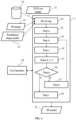
- the device 1 is adapted to produce the 3D model 31 of the exposed target anatomical structure T and information indicative of the rigid transformation 32. This information, once obtained during the surgery, may be used to correctly reproduce the predefined surgical actions planned beforehand in the preoperative surgical planning.
- modules are to be understood as functional entities rather than material, physically distinct, components. They can consequently be embodied either as grouped together in a same tangible and concrete component, or distributed into several such components. Also, each of these modules are possibly themselves shared between at least two physical components. In addition, the modules are implemented in hardware, software, firmware, or any mixed form thereof as well. They are preferably embodied within at least one processor of the device 1.
- the device 1 comprises a module 11 for receiving the following input data: at least one 2D X-ray image 21, at least one 3D image 22 and a predefined shape model 23 of the target anatomical structure T. All these input data may be stored in one or more local or remote database(s) 10.
- the latter can take the form of storage resources available from any kind of appropriate storage means, which can be notably a RAM or an EEPROM (Electrically-Erasable Programmable Read-Only Memory) such as a Flash memory, possibly within an SSD (Solid-State Disk).
- the 2D X-ray images 21 comprising at least one portion of the target anatomical structure T.
- the target anatomical structure T represented in the 2D X-ray images 21 is a femur or a tibia. More generally, the target anatomical structure T can be any bone structure.
- at least two or three 2D X-ray images 21 are received as input in the module 11 to improve the quality of the 3D model 31 to produce. Said at least two or three 2D X-ray image are acquired from different angles, as known by the skilled person. Generally, acquisition of multiple 2D X-ray images 21 is included in the clinical routine for patient that will undergo TKA surgery.
- the 3D image 22 received from the module 11 are acquired from at least one 3D imaging sensor during surgery.
- the at least one 3D image 22 comprises data points representing at least one exposed portion of the target anatomical structure T (e.g., femur or tibia).
- the module 11 is configured to receive the 3D image 22, for example from a communication network, from the at least one 3D imaging sensor which is present in the surgical theater and positioned in such a way to comprise in its field of view at least a portion of the surgical field comprising the target anatomical structure T.
- the surgeon proceeds to the exposure of the target anatomical structure T, which in this case may be a bone, on which surgical operations, such as for example, machining or drilling have to be performed.
- the surgical field which is basically the region of the patient on which the surgery is to be performed, will comprise the exposed target anatomical structure T and the surrounding structures B such as tissues (i.e., cartilages, tendons, muscles, skin, or a bone which is not targeted during the surgery, and the like) and/or artificial structures (i.e., bone screw, surgical tools, grasping tools etc.).
- tissues i.e., cartilages, tendons, muscles, skin, or a bone which is not targeted during the surgery, and the like
- artificial structures i.e., bone screw, surgical tools, grasping tools etc.
- the 3D imaging sensor refers to a sensor for acquiring topological data of a real scene in 3 dimensions. These topological data are recorded in the form of a point cloud, and/or a depth map.
- data points will be used to refer both to the point clouds or depth maps, as the person skilled in the art knows how to perform registration on both point clouds or depth maps. Therefore, at least one portion of the data points of one 3D image 22 represents at least one exposed portion of the target anatomical structure T of the patient.
- the other data points are generally associated to the structures surrounding the target anatomical structure T comprised in the field of view of the 3D imaging sensor.
- Multiple acquisition techniques may be utilized to obtain these topological data for example techniques based on the measure of wave propagation time such as ultrasound or light (LIDAR, Time-of-Flight) or stereoscopic camera or sensor, which is a type of camera with two or more lenses with a separate image sensor or film frame for each lens. This allows the camera to simulate human binocular vision, and therefore gives it the ability to capture three-dimensional images.
- Other techniques may be based on light deformation, such as structured-light 3D scanners which project a pattern of light on an object and look at the deformation of the pattern on the object. The advantage of structured-light 3D scanners is speed and precision. Instead of scanning one point at a time, structured light scanners scan multiple points or the entire field of view at once.
- the 3D image(s) 22 may be grayscale images, or colored depth (RGB-D) images among others.
- the 3D image(s) 22 may include numerical data, such as digital data. Those data may include individual image data in a compressed form, as well known to a person skilled in image compression, such as e.g., in compliance with e.g., in compliance with JPEG (for Joint Photographic Experts Group), JPEG 2000 or HEIF (for High Efficiency Image File Format) standard.
- JPEG Joint Photographic Experts Group
- JPEG 2000 Joint Photographic Experts Group
- HEIF High Efficiency Image File Format
- the data points of the 3D images are associated to a sensor referential, notably the referential of the 3D imaging sensor.
- the 3D image(s) 22 may be derived from a unique 3D imaging sensor used to acquire at least one 3D image of at least a portion of the surgical field comprising the target anatomical structure T.
- the 3D image(s) 22 may be derived from two or more 3D imaging sensors, or even from two or more different kinds of 3D imaging sensors. In this case, data from multiple sensors could be combined into a single fused point cloud or depth map.
- the 3D point cloud could also be obtained via the digitization of the target anatomical structure's surface using a probe tracked by an optical tracking system.
- the predefined shape model 23 may be the mean shape from a statistical shape model (SSM) that realistically describes the anatomy of the target anatomical structure T.
- the statistical shape model (SSM) also describes the variation of the anatomy of the target anatomical structure T in any population by conventional multivariate statistics of dense sets of homologous landmarks representing the shape of the underlying structures.
- Statistical shape modeling provides a powerful tool for describing the target T anatomy. By linearly combining the variance of the shape of a population of patients, statistical shape models (SSMs) identify its main modes of variation and may approximate the total variance of that population to a selected threshold, while reducing its dimensionality.
- the predefined shape model 23 may be retrieved from a database 10 or alternatively it may be calculated from a modeling module (not represented) part of the device 1. In one example, the predefined shape model 23 is generated based on demographic data and/or diagnosis information of the patient.
- the modeling module may be configured to access large database of 3D meshes of bones (i.e., including the target anatomical structure T) from patients, from a population representative of the target patients for the surgical procedure concerned. These 3D meshes of bones are coarsely aligned by the automatic placement of anatomical landmarks, enabling their rigid registration. A groupwise deformable registration algorithm may be then applied to these bones meshes, allowing a dense matching of surface points.
- a statistical model of the bone shape is obtained by performing a principal component analysis (PCA) on a densely sampled subset of points within the registered surfaces.
- PCA principal component analysis
- This statistical model describes the morphologic features of the set of bone models from the input data, synthetically into a space of fundamental modes of variations.
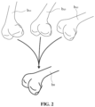
- the calculation of the statistical shape model is schematically represented in Figure 2 , where the bone database can be expressed as a combination of a mean shape and of a set of parameters b 1,1 , b 2,1 , b 3,1 ... representing principal modes of variation.
- a given bone mesh b x . can be computed via a linear combination of the mean shape and these parameters.
- Other methods for the generation of a statistical shape model may be used by the modeling module as known by the person skilled in the art.
- the modeling module is configured to generate the predefined shape model 23 comprising a statistical shape model of a femur of the patient (i.e., target anatomical structure T) representing the totality of the bone surface or at least the portion of the bone surface on which the surgeon as to operate, notably the femur head and the distal part of the femur.
- the SSM module is configured to generate the predefined shape model 23 further comprising a statistical shape model of the femur representing the integrality of the bone surface of the distal or proximal epiphysis.
- the modeling module is configured to access a database of femurs and tibias 3D models, extracted from a series of segmented CT scans.
- the modeling module then jointly registers them to each other through a landmark matching algorithm after a first manual alignment.
- a statistical shape model is then built by sampling arbitrary landmarks uniformly on the registered surfaces and applying the inverse transformation of each shape to recover the position of each landmark in each original shape.
- the resulting model contains information of the mean shape and its variations with respect to the database.
- Principal Component Analysis is then used on the bone database to find parameters modelling the shapes variations.
- PCA Principal Component Analysis
- the device 1 may further comprise a module 12 configured to perform the step a of setting a candidate 3D shape based on the predefined shape model 23.
- the candidate 3D shape may be chosen as an average model among models from a large database of 3D meshes of bones (i.e., including the target anatomical structure T) from patients, from a population representative of the target patients for the surgical procedure concerned.
- the module 12 may be configured to perform an optional step of preprocessing of the 2D X-ray image(s) 21 configured to segment the contours of the bones represented in the 2D X-ray image(s) 21.
- the device 1 also comprises a module 13 configured to perform the step b of computing a 2D digitally reconstructed radiography image using a digitally reconstructed radiography processing function on the candidate 3D shape.
- processing functions are raycasting, splatting and voxel projection algorithms, shear-warp factorization, or light fields algorithms.
- a segmentation step may be implemented on the 2D digitally reconstructed radiography image so as to extract the 2D contours of the target anatomical structure T.
- the 2D digitally reconstructed radiography may be computed using a raytracing algorithm.
- a module 14 of the device 1 may be configured to perform the step c of registering a corresponding portion of said candidate 3D shape to at least part of the 3D image data points 22. This process yields an estimate of a rigid transformation that aligns the 3D image data points to the candidate 3D shape.
- the module 14 may be configured to perform a preprocessing step configured to filter the 3D image data points 22 so as to remove as much as possible data points associated to noise, artefacts or tissues that does not belong to the target anatomical structure T.
- the device 1 further comprises a scoring module 15 configured to perform steps d, e, and f of calculating the matching score, the registration score and the iteration score.
- the scoring module 15 may calculate the matching score, between the 2D digitally reconstructed radiography model and the at least one 2D X-ray image 21, using different intensity-based similarity metrics such as normalized cross-correlation, entropy of difference, gradient correlation or gradient difference.
- intensity-based similarity metrics such as normalized cross-correlation, entropy of difference, gradient correlation or gradient difference.
- the definition of such metrics is for example given in the article " Comparison of similarity measures for rigid-body CT/Dual X-ray image registrations", by Kim, Jinkoo, et al, Technology in cancer research & treatment 6.4 (2007): 337-345 ".
- the matching score may be calculated as pixel to pixel mean square distance, or a pixel-wise mean squared error.
- the matching score is calculated as weighted function, wherein the weights are determined on the base of the confidence associated to pixels in the 2D X-ray image 21. For instance, when the target anatomical structure T is a bone, pixels corresponding to the bone contours hold higher confidence.
- the scoring module 15 may calculate the registration score using different type of methods.
- the registration score is a point-to-plane error metric, corresponding to the minimization of the sum of the squared distances between the data points of the candidate 3D shape and the tangent plane at the corresponding data points in the 3D image.
- the registration score may be function of the square root of the average squared distances between data points of the candidate 3D shape for the current iteration and the corresponding data points in the 3D image 22.
- the registration score is calculated as a weighted function wherein the weights are determined on the base of the confidence associated to the data points of the 3D image 22.
- the target anatomical structure T is a bone
- points corresponding to the center of the bone hold higher confidence than for instance points corresponding to edges of the bone.
- the resulting localization of the edges could be biased by soft tissues located on the edges.
- the order of calculation between matching score and the registration score may be inversed.
- the scoring module 15 is then configured to calculate an iteration score as a function of said registration score and said matching score.
- This function is referred to as iteration function.
- the iteration score may be obtained as a linear combination, such a sum or a weighted sum, of the registration score and said matching score.
- the weights are configured to be adapted during the iterations according to the variations of the current cost value or the total number of iterations, according to an optimization algorithm.
- the device 1 further comprises a verification module 16 for determining whether the iteration score satisfies a predetermined exit criterion.
- the verification module 16 is configured to compare the iteration score to a predefined threshold.
- the predefined threshold is empirically determined via off-line tests, where models from known databases, or computed from cadaveric samples, are tested.
- the predefined exit criterion is configured to stop the iterations when, for a given number of iterations, the iteration score is unchanged.
- the device 1 further comprises a deformation module 17 to perform the step h.
- module 17 is configured to, in response of the fact that module 16 has determined that the predefined exit criterion is not satisfied, deform the candidate 3D shape based on the calculated iteration score. More precisely, at step h, a set of deformation parameters are updated according to the variations of the iteration function via an optimization algorithm.
- the deformation parameters are the parameters found by the previously applied Principal Component Analysis (PCA) and which model the shapes variations.
- the deformation parameters are mathematical quantities.
- module 17 sets the deformed 3D candidate shape as candidate 3D shape for a new iteration and therefore triggers instructions for repeating steps (b)-(i) (i.e., the new iteration).
- the device 1 further comprises an exit module 18 to perform the step i.
- This module 18 is configured to set the 3D model 31 as the 3D candidate shape and outputting the 3D model 31 and information indicative of the rigid transformation 32, whenever the module 16 determines the exit criterion is satisfied.
- the device 1 is interacting with a user interface 19, via which information can be entered and retrieved by a user.
- the user interface 19 includes any means appropriate for entering or retrieving data, information or instructions, notably visual, tactile and/or audio capacities that can encompass any or several of the following means as well known by a person skilled in the art: a screen, a keyboard, a trackball, a touchpad, a touchscreen, a loudspeaker, a voice recognition system.
- the device 1 may for example execute the following process illustrated on Figure 3 :
- Figure 4 illustrates a process of capturing a set of 3D data points 22 with a 3D imaging sensor.
- Figure 4a shows a 3D imaging sensor 10 and a femur 11 of a patient.
- Figure 4b shows a set of 3D image data points 22 captured by the 3D imaging sensor 10.
- Figure 5a shows the predefined shape model at the first iteration superimposed to the set of 3D data points 22.
- Figure 5b shows several iterations R 1 of step h (or step 47) of deforming the candidate 3D shape based on the iteration score.
- the iteration R 1 allows reducing distances such as a distance d 1X indicated on Figure 5b between the current candidate 3D shape and the 3D image 22.
- Figure 5b further shows a second iteration R 2 successive to the first iteration R 2 , where the candidate 3D shape is once again deformed, so that the distance d1X is further reduced.
- a particular apparatus 9, visible on Figure 6 is embodying the device 1 described above. It corresponds for example to a workstation, a laptop, a tablet, a smartphone, or a head-mounted display (HMD).
- a workstation a laptop, a tablet, a smartphone, or a head-mounted display (HMD).
- HMD head-mounted display
- the apparatus 9 comprises a memory 91 to store program instructions loadable into a circuit and adapted to cause a circuit 92 to carry out steps of the method of Figure 4 when the program instructions are run by the circuit 92.
- the memory 91 may also store data and useful information for carrying steps of the present invention as described above.
- the circuit 92 may be for instance:
- the apparatus 9 may also comprise an input interface 93 for the reception of the at least one 2D X-ray image 21, the predefined shape model 23 and the 3D image 22, and an output interface 94 to provide the 3D model 31.
- the input interface 93 and the output interface 84 may together correspond to the user interface 19 of Figure 1 .
- a screen 95 and a keyboard 96 may be provided and connected to the computer circuit 92.
Landscapes
- Engineering & Computer Science (AREA)
- Physics & Mathematics (AREA)
- General Physics & Mathematics (AREA)
- Theoretical Computer Science (AREA)
- Health & Medical Sciences (AREA)
- Medical Informatics (AREA)
- Computer Vision & Pattern Recognition (AREA)
- Public Health (AREA)
- Life Sciences & Earth Sciences (AREA)
- Computer Graphics (AREA)
- Biomedical Technology (AREA)
- Software Systems (AREA)
- Pathology (AREA)
- General Health & Medical Sciences (AREA)
- Databases & Information Systems (AREA)
- Primary Health Care (AREA)
- Epidemiology (AREA)
- Data Mining & Analysis (AREA)
- Geometry (AREA)
- Orthopedic Medicine & Surgery (AREA)
- Biophysics (AREA)
- High Energy & Nuclear Physics (AREA)
- Nuclear Medicine, Radiotherapy & Molecular Imaging (AREA)
- Optics & Photonics (AREA)
- Radiology & Medical Imaging (AREA)
- Heart & Thoracic Surgery (AREA)
- Molecular Biology (AREA)
- Surgery (AREA)
- Animal Behavior & Ethology (AREA)
- Veterinary Medicine (AREA)
- Oral & Maxillofacial Surgery (AREA)
- Dentistry (AREA)
- Apparatus For Radiation Diagnosis (AREA)
- Image Processing (AREA)
Claims (15)
- Vorrichtung (1) zur Rekonstruktion eines 3D-Modells (31) einer exponierten anatomischen Zielstruktur (T) eines Patienten während einer Operation, wobei die Vorrichtung (1) umfasst:- mindestens einen Eingang, der konfiguriert ist zum Empfangen von:• mindestens einem 2D-Röntgenbild (21), das mindestens einen Bereich der anatomischen Zielstruktur (T) umfasst;• mindestens einem 3D-Bild (22), das von mindestens einem 3D-Bildgebungssensor während einer Operation aufgenommen wurde, wobei das mindestens eine 3D-Bild (22) Datenpunkte umfasst, die mindestens einen exponierten Bereich der anatomischen Zielstruktur (T) repräsentieren;• einem vordefinierten Formmodell (23) der anatomischen Zielstruktur (T);- mindestens einen Prozessor, der konfiguriert ist, um das 3D-Modell (31) der exponierten anatomischen Zielstruktur über ein iteratives Verfahren zu kalkulieren, das den nachfolgenden Schritten folgt:a) Festlegen einer 3D-Kandidaten-Form basierend auf dem vordefinierten Formmodell (23);b) Kalkulieren eines digital rekonstruierten 2D-Radiographiemodells unter Verwendung einer digital rekonstruierten Radiographie-Verarbeitungsfunktion, die durch einen Satz von Projektionsparametern auf der 3D-Kandidaten-Form gekennzeichnet ist;c) Registrieren eines entsprechenden Bereichs der 3D-Kandidaten-Form zu mindestens einem Teil der 3D-Bild-Datenpunkte (22), und Kalkulieren einer Ähnlichkeitstransformation (32) zwischen den Datenpunkten der 3D-Kandidaten-Form und entsprechenden Datenpunkten des 3D-Bildes (22);d) Berechnen eines Übereinstimmungswerts zwischen dem digital rekonstruierten 2D-Radiographiemodell und dem mindestens einen 2D-Röntgenbild (21);e) Berechnen eines Registrierungswerts, der für einen Restabstand zwischen Datenpunkten der 3D-Kandidaten-Form und entsprechenden Datenpunkten des 3D-Bildes (22) repräsentativ ist;f) Berechnen eines Iterationswerts als Funktion des Registrierungswerts und des Übereinstimmungswerts, wobei die Funktion als Iterationsfunktion bezeichnet wird;g) Bestimmen, ob der Iterationswert ein vorbestimmtes Ausgangskriterium erfüllt;h) als Reaktion auf das Bestimmen, dass das vordefinierte Ausgangskriterium nicht erfüllt ist, Aktualisieren der Projektionsparameter der digital rekonstruierten Radiographie-Verarbeitungsfunktion, und Anwenden eines Satzes von Verformungsparametern auf die 3D-Kandidaten-Form, die alle basierend auf dem Iterationswert kalkuliert werden und einem Gradienten, der aus der Iterationsfunktion kalkuliert wird, und Wiederholen der Schritte (b) - (i), wobei die verformte 3D-Kandidatenform als die 3D-Kandidaten-Form festgelegt wird; undi) als Reaktion auf das Bestimmen, dass das Ausgangskriterium erfüllt ist, Festlegen des 3D-Modells (31) als die 3D-Kandidatenform, und Ausgeben des 3D-Modells (31) und Informationen, die die Ähnlichkeitstransformation (32) anzeigen.
- Vorrichtung nach Anspruch 1, wobei der Registrierungswert eine Punkt-zu-Ebene-Fehlermetrik zwischen Datenpunkten der 3D-Kandidaten-Form und einer Tangentialebene an den entsprechenden Datenpunkten im 3D-Bild (22) ist.
- Vorrichtung nach Anspruch 1, wobei der Registrierungswert eine Funktion der Quadratwurzel der durchschnittlichen quadratischen Abstände zwischen Datenpunkten der 3D-Kandidaten-Form und den entsprechenden Datenpunkten im 3D-Bild (22) ist.
- Vorrichtung nach einem der Ansprüche 1 bis 3, wobei die digital rekonstruierte 2D-Radiographie unter Verwendung eines Strahlenverfolgungs-Algorithmus kalkuliert wird.
- Vorrichtung nach einem der Ansprüche 1 bis 4, wobei die Datenpunkte des 3D-Bildes (22) gefiltert wurden, um Datenpunkte auszuschließen, die für andere anatomische Strukturen als die anatomische Zielstruktur (T) repräsentativ sind, und/oder Datenpunkte, die sich auf Rauschen beziehen.
- Vorrichtung nach einem der Ansprüche 1 bis 5, wobei das Bestimmen, ob der Iterationswert ein vorbestimmtes Ausgangskriterium erfüllt, das Vergleichen des Iterationswerts mit einem vordefinierten Schwellenwert umfasst.
- Vorrichtung nach einem der Ansprüche 1 bis 6, wobei das vordefinierte Ausgangskriterium konfiguriert ist, um die Iterationen zu stoppen, wenn, für eine gegebene Anzahl von Iterationen, Änderungen im Iterationswert kleiner als ein gegebener Schwellenwert sind.
- Vorrichtung nach einem der Ansprüche 1 bis 7, wobei das vordefinierte Formmodell (23) ein statistisches Formmodell ist.
- Vorrichtung nach einem der Ansprüche 1 bis 8, wobei der Iterationswert eine gewichtete Funktion des Registrierungswerts und des Übereinstimmungswerts ist, wobei die Gewichtungen konfiguriert sind, um sich während der Iterationen zu entwickeln.
- Vorrichtung nach einem der Ansprüche 1 bis 9, wobei der Registrierungswert und der Übereinstimmungswert als gewichtete Funktion berechnet werden, wobei die Gewichtungen auf der Basis des Vertrauens bestimmt werden, das jeweils mit den Datenpunkten des 3D-Bildes (22) und den Pixeln im 2D-Röntgenbild (21) assoziiert ist.
- Vorrichtung nach einem der Ansprüche 1 bis 10, wobei der Übereinstimmungswert als eine Ähnlichkeitsfunktion zwischen den Pixeln des 2D-Röntgenbilds (21) und den Pixeln der digital rekonstruierten 2D-Radiographie berechnet wird, wobei die Ähnlichkeitsfunktion ausgewählt wird unter: kontinuierlicher Dice, mittlerer quadratischer Abstand von Pixel zu Pixel, pixelweiser mittlerer quadratischer Fehler, Übereinstimmung der Bildmerkmale.
- Vorrichtung nach einem der Ansprüche 1 bis 11, wobei das vordefinierte Formmodell (23) basierend auf demografischen Daten, medizinischen Bildgebungsdaten und/oder Diagnoseinformationen des Patienten erzeugt wird.
- Vorrichtung nach einem der Ansprüche 1 bis 12, wobei das vordefinierte Formmodell (23), das mit der anatomischen Zielstruktur (T) assoziiert ist, eine Repräsentation von mindestens einem Knochen und optional mindestens einem Knorpel umfasst.
- Computerimplementiertes Verfahren zur Rekonstruktion eines 3D-Modells (31) einer exponierten anatomischen Zielstruktur (T) eines Patienten während einer Operation, wobei das Verfahren umfasst:- Empfangen von:• mindestens einem 2D-Röntgenbild (21), das mindestens einen Bereich der anatomischen Zielstruktur (T) umfasst;• mindestens einem 3D-Bild (22), das von mindestens einem 3D-Bildgebungssensor während einer Operation aufgenommen wurde, wobei das mindestens eine 3D-Bild (22) Datenpunkte umfasst, die mindestens einen exponierten Bereich der anatomischen Zielstruktur (T) repräsentieren;• einem vordefinierten Formmodell (23) der anatomischen Zielstruktur (T);a) Festlegen einer 3D-Kandidaten-Form basierend auf dem vordefinierten Formmodell (23);b) Kalkulieren einer digital rekonstruierten 2D-Radiographie unter Verwendung einer digital rekonstruierten Radiographie-Verarbeitungsfunktion, die durch einen Satz von Projektionsparametern auf die 3D-Kandidaten-Form (23) gekennzeichnet ist;c) Registrieren eines entsprechenden Bereichs der 3D-Kandidaten-Form zu mindestens einem Teil der Datenpunkte (22), und Kalkulieren einer Ähnlichkeitstransformation (32) zwischen den Datenpunkten der 3D-Kandidaten-Form und entsprechenden Datenpunkten des 3D-Bildes (22);d) Berechnen eines Übereinstimmungswerts zwischen der digital rekonstruierten 2D-Radiographie und dem mindestens einen 2D-Röntgenbild;e) Berechnen eines Registrierungswerts, der für einen Restabstand zwischen Datenpunkten der 3D-Kandidaten-Form und entsprechenden Datenpunkten des 3D-Bildes (22) repräsentativ ist, durch Kalkulieren einer starren Transformation zwischen der 3D-Kandidaten-Form und entsprechenden Datenpunkten des 3D-Bildes (22);f) Berechnen eines Iterationswerts als Funktion des Registrierungswerts und des Übereinstimmungswerts, wobei die Funktion als Iterationsfunktion bezeichnet wird;g) Bestimmen, ob der Iterationswert das vorbestimmte Ausgangskriterium erfüllt;h) als Reaktion auf das Bestimmen, dass das Ausgangskriterium nicht erfüllt ist, Aktualisieren der Projektionsparameter der digital rekonstruierten Radiographie-Verarbeitungsfunktion, und Anwenden eines Satzes von Verformungsparametern auf die 3D-Kandidatenform, die alle basierend auf dem Iterationswert kalkuliert werden und einem Gradienten, der aus der Iterationsfunktion kalkuliert wird, und Wiederholen der Schritte (b) - (i), wobei die verformte 3D-Kandidatenform als die 3D-Kandidaten-Form festgelegt wird; undi) als Reaktion auf das Bestimmen, dass das Ausgangskriterium erfüllt ist, Festlegen des 3D-Modells (31) als die 3D-Kandidatenform, und Ausgeben des 3D-Modells und Informationen, die die Ähnlichkeitstransformation anzeigen.
- Computerlesbares Medium, Anweisungen umfassend, die, wenn sie von einem Computer ausgeführt werden, den Computer veranlassen, das Verfahren nach Anspruch 14 durchzuführen.
Priority Applications (5)
| Application Number | Priority Date | Filing Date | Title |
|---|---|---|---|
| ES23305038T ES3001435T3 (en) | 2023-01-11 | 2023-01-11 | Device and method for intraoperative reconstruction of bone 3d models |
| EP23305038.4A EP4401036B1 (de) | 2023-01-11 | 2023-01-11 | Vorrichtung und verfahren zur intraoperativen rekonstruktion von knochen-3d-modellen |
| PCT/EP2024/050613 WO2024149851A1 (en) | 2023-01-11 | 2024-01-11 | Device and method for intraoperative reconstruction of bone 3d models |
| US18/410,211 US12056822B2 (en) | 2023-01-11 | 2024-01-11 | Device and method for intraoperative reconstruction of bone 3D models |
| US18/794,137 US20240394982A1 (en) | 2023-01-11 | 2024-08-05 | Device and method for intraoperative reconstruction of bone 3d models |
Applications Claiming Priority (1)
| Application Number | Priority Date | Filing Date | Title |
|---|---|---|---|
| EP23305038.4A EP4401036B1 (de) | 2023-01-11 | 2023-01-11 | Vorrichtung und verfahren zur intraoperativen rekonstruktion von knochen-3d-modellen |
Publications (3)
| Publication Number | Publication Date |
|---|---|
| EP4401036A1 EP4401036A1 (de) | 2024-07-17 |
| EP4401036B1 true EP4401036B1 (de) | 2024-12-25 |
| EP4401036C0 EP4401036C0 (de) | 2024-12-25 |
Family
ID=85328802
Family Applications (1)
| Application Number | Title | Priority Date | Filing Date |
|---|---|---|---|
| EP23305038.4A Active EP4401036B1 (de) | 2023-01-11 | 2023-01-11 | Vorrichtung und verfahren zur intraoperativen rekonstruktion von knochen-3d-modellen |
Country Status (4)
| Country | Link |
|---|---|
| US (2) | US12056822B2 (de) |
| EP (1) | EP4401036B1 (de) |
| ES (1) | ES3001435T3 (de) |
| WO (1) | WO2024149851A1 (de) |
Families Citing this family (1)
| Publication number | Priority date | Publication date | Assignee | Title |
|---|---|---|---|---|
| WO2025153699A1 (en) * | 2024-01-19 | 2025-07-24 | Ganymed Robotics | Device and method for obtaining an augmented patient-specific bone/cartilage model of a target anatomical structure of a patient |
Family Cites Families (2)
| Publication number | Priority date | Publication date | Assignee | Title |
|---|---|---|---|---|
| EP2006803A1 (de) * | 2007-06-19 | 2008-12-24 | Agfa HealthCare NV | Verfahren zur Segmentierung anatomischer Entitäten in medizinischen 3D-Bildern |
| EP3061015A2 (de) * | 2013-10-24 | 2016-08-31 | Cathworks Ltd. | Bestimmung vaskulärer eigenschaften mit korrespondenzmodellierung eines gefässbaums |
-
2023
- 2023-01-11 EP EP23305038.4A patent/EP4401036B1/de active Active
- 2023-01-11 ES ES23305038T patent/ES3001435T3/es active Active
-
2024
- 2024-01-11 WO PCT/EP2024/050613 patent/WO2024149851A1/en not_active Ceased
- 2024-01-11 US US18/410,211 patent/US12056822B2/en active Active
- 2024-08-05 US US18/794,137 patent/US20240394982A1/en active Pending
Also Published As
| Publication number | Publication date |
|---|---|
| WO2024149851A1 (en) | 2024-07-18 |
| US12056822B2 (en) | 2024-08-06 |
| US20240233267A1 (en) | 2024-07-11 |
| ES3001435T3 (en) | 2025-03-05 |
| EP4401036C0 (de) | 2024-12-25 |
| EP4401036A1 (de) | 2024-07-17 |
| US20240394982A1 (en) | 2024-11-28 |
Similar Documents
| Publication | Publication Date | Title |
|---|---|---|
| EP3726467B1 (de) | Systeme und verfahren zur rekonstruktion von anatomischen 3d-bildern aus anatomischen 2d-bildern | |
| Maken et al. | 2D-to-3D: a review for computational 3D image reconstruction from X-ray images | |
| EP2996599B1 (de) | Planungsverfahren zur chirurgischen korrektur von abnormalen knochen | |
| EP3074951B1 (de) | System und verfahren zur erzeugung einer teilfläche aus volumetrischen daten zur registrierung auf oberflächentopologiebilddaten | |
| JP5882743B2 (ja) | カスタマイズされた整形外科用インプラント及び関連する方法並びにインテリジェント軟骨システム | |
| Eiben et al. | Symmetric biomechanically guided prone-to-supine breast image registration | |
| US12272082B2 (en) | Method and system for constructing bone model, medium and device | |
| US20240005504A1 (en) | Standardizing images of anatomical structures for analysis by machine learning systems | |
| US20240394982A1 (en) | Device and method for intraoperative reconstruction of bone 3d models | |
| Fleute et al. | Integrated approach for matching statistical shape models with intra-operative 2D and 3D data | |
| US20260076745A1 (en) | Device and method for obtaining an augmented patient-specific bone/cartilage model of a target anatomical structure of a patient | |
| JP2019500114A (ja) | 位置合わせ精度の決定 | |
| US12575894B2 (en) | Method and device for segmentation and registration of an anatomical structure | |
| Haque et al. | A fast and robust technique for 3D–2D registration of CT to single plane X-ray fluoroscopy | |
| Yang et al. | A novel neurosurgery registration pipeline based on heat maps and anatomic facial feature points | |
| EP4586215A1 (de) | Präzise körperschlüsselpunktdetektion unter verwendung von rein synthetischen daten zur arbeitsflussunterstützung | |
| Saadat et al. | An efficient image registration method for 3D post-operative analysis of total knee arthroplasty | |
| Saadat | Multi-modal Image Registration | |
| de Almeida Moreira | Neural Radiance Fields in Orthopedics | |
| Jin et al. | Active illumination based 3D surface reconstruction and registration for image guided medialization laryngoplasty | |
| Jin et al. | Image guided medialization laryngoplasty | |
| El Dakhakhni | Reconstruction of Patient-Specific Bone Models from X-Ray Radiography | |
| HK40031870B (en) | Systems and methods for reconstruction of 3d anatomical images from 2d anatomical images | |
| HK40031870A (en) | Systems and methods for reconstruction of 3d anatomical images from 2d anatomical images | |
| Badakhshannoory | Model based validation scheme for organ segmentation in medical image data |
Legal Events
| Date | Code | Title | Description |
|---|---|---|---|
| STAA | Information on the status of an ep patent application or granted ep patent |
Free format text: STATUS: EXAMINATION IS IN PROGRESS |
|
| PUAI | Public reference made under article 153(3) epc to a published international application that has entered the european phase |
Free format text: ORIGINAL CODE: 0009012 |
|
| 17P | Request for examination filed |
Effective date: 20240306 |
|
| AK | Designated contracting states |
Kind code of ref document: A1 Designated state(s): AL AT BE BG CH CY CZ DE DK EE ES FI FR GB GR HR HU IE IS IT LI LT LU LV MC ME MK MT NL NO PL PT RO RS SE SI SK SM TR |
|
| GRAP | Despatch of communication of intention to grant a patent |
Free format text: ORIGINAL CODE: EPIDOSNIGR1 |
|
| STAA | Information on the status of an ep patent application or granted ep patent |
Free format text: STATUS: GRANT OF PATENT IS INTENDED |
|
| INTG | Intention to grant announced |
Effective date: 20240725 |
|
| GRAS | Grant fee paid |
Free format text: ORIGINAL CODE: EPIDOSNIGR3 |
|
| GRAA | (expected) grant |
Free format text: ORIGINAL CODE: 0009210 |
|
| STAA | Information on the status of an ep patent application or granted ep patent |
Free format text: STATUS: THE PATENT HAS BEEN GRANTED |
|
| AK | Designated contracting states |
Kind code of ref document: B1 Designated state(s): AL AT BE BG CH CY CZ DE DK EE ES FI FR GB GR HR HU IE IS IT LI LT LU LV MC ME MK MT NL NO PL PT RO RS SE SI SK SM TR |
|
| RAP3 | Party data changed (applicant data changed or rights of an application transferred) |
Owner name: GANYMED ROBOTICS |
|
| REG | Reference to a national code |
Ref country code: GB Ref legal event code: FG4D |
|
| REG | Reference to a national code |
Ref country code: CH Ref legal event code: EP |
|
| REG | Reference to a national code |
Ref country code: DE Ref legal event code: R096 Ref document number: 602023001506 Country of ref document: DE |
|
| REG | Reference to a national code |
Ref country code: IE Ref legal event code: FG4D |
|
| U01 | Request for unitary effect filed |
Effective date: 20250120 |
|
| U07 | Unitary effect registered |
Designated state(s): AT BE BG DE DK EE FI FR IT LT LU LV MT NL PT RO SE SI Effective date: 20250127 |
|
| U20 | Renewal fee for the european patent with unitary effect paid |
Year of fee payment: 3 Effective date: 20250221 |
|
| PGFP | Annual fee paid to national office [announced via postgrant information from national office to epo] |
Ref country code: IE Payment date: 20250130 Year of fee payment: 3 |
|
| PG25 | Lapsed in a contracting state [announced via postgrant information from national office to epo] |
Ref country code: NO Free format text: LAPSE BECAUSE OF FAILURE TO SUBMIT A TRANSLATION OF THE DESCRIPTION OR TO PAY THE FEE WITHIN THE PRESCRIBED TIME-LIMIT Effective date: 20250325 |
|
| PG25 | Lapsed in a contracting state [announced via postgrant information from national office to epo] |
Ref country code: GR Free format text: LAPSE BECAUSE OF FAILURE TO SUBMIT A TRANSLATION OF THE DESCRIPTION OR TO PAY THE FEE WITHIN THE PRESCRIBED TIME-LIMIT Effective date: 20250326 |
|
| PG25 | Lapsed in a contracting state [announced via postgrant information from national office to epo] |
Ref country code: RS Free format text: LAPSE BECAUSE OF FAILURE TO SUBMIT A TRANSLATION OF THE DESCRIPTION OR TO PAY THE FEE WITHIN THE PRESCRIBED TIME-LIMIT Effective date: 20250325 |
|
| PG25 | Lapsed in a contracting state [announced via postgrant information from national office to epo] |
Ref country code: SM Free format text: LAPSE BECAUSE OF FAILURE TO SUBMIT A TRANSLATION OF THE DESCRIPTION OR TO PAY THE FEE WITHIN THE PRESCRIBED TIME-LIMIT Effective date: 20241225 |
|
| PG25 | Lapsed in a contracting state [announced via postgrant information from national office to epo] |
Ref country code: PL Free format text: LAPSE BECAUSE OF FAILURE TO SUBMIT A TRANSLATION OF THE DESCRIPTION OR TO PAY THE FEE WITHIN THE PRESCRIBED TIME-LIMIT Effective date: 20241225 |
|
| PG25 | Lapsed in a contracting state [announced via postgrant information from national office to epo] |
Ref country code: IS Free format text: LAPSE BECAUSE OF FAILURE TO SUBMIT A TRANSLATION OF THE DESCRIPTION OR TO PAY THE FEE WITHIN THE PRESCRIBED TIME-LIMIT Effective date: 20250425 |
|
| PG25 | Lapsed in a contracting state [announced via postgrant information from national office to epo] |
Ref country code: SK Free format text: LAPSE BECAUSE OF FAILURE TO SUBMIT A TRANSLATION OF THE DESCRIPTION OR TO PAY THE FEE WITHIN THE PRESCRIBED TIME-LIMIT Effective date: 20241225 |
|
| PG25 | Lapsed in a contracting state [announced via postgrant information from national office to epo] |
Ref country code: CZ Free format text: LAPSE BECAUSE OF FAILURE TO SUBMIT A TRANSLATION OF THE DESCRIPTION OR TO PAY THE FEE WITHIN THE PRESCRIBED TIME-LIMIT Effective date: 20241225 |
|
| PG25 | Lapsed in a contracting state [announced via postgrant information from national office to epo] |
Ref country code: MC Free format text: LAPSE BECAUSE OF FAILURE TO SUBMIT A TRANSLATION OF THE DESCRIPTION OR TO PAY THE FEE WITHIN THE PRESCRIBED TIME-LIMIT Effective date: 20241225 |
|
| PLBE | No opposition filed within time limit |
Free format text: ORIGINAL CODE: 0009261 |
|
| STAA | Information on the status of an ep patent application or granted ep patent |
Free format text: STATUS: NO OPPOSITION FILED WITHIN TIME LIMIT |
|
| REG | Reference to a national code |
Ref country code: CH Ref legal event code: L10 Free format text: ST27 STATUS EVENT CODE: U-0-0-L10-L00 (AS PROVIDED BY THE NATIONAL OFFICE) Effective date: 20251105 |
|
| 26N | No opposition filed |
Effective date: 20250926 |
|
| REG | Reference to a national code |
Ref country code: CH Ref legal event code: U11 Free format text: ST27 STATUS EVENT CODE: U-0-0-U10-U11 (AS PROVIDED BY THE NATIONAL OFFICE) Effective date: 20260201 |
|
| U20 | Renewal fee for the european patent with unitary effect paid |
Year of fee payment: 4 Effective date: 20260129 |
|
| PGFP | Annual fee paid to national office [announced via postgrant information from national office to epo] |
Ref country code: ES Payment date: 20260227 Year of fee payment: 4 |
|
| PG25 | Lapsed in a contracting state [announced via postgrant information from national office to epo] |
Ref country code: HR Free format text: LAPSE BECAUSE OF FAILURE TO SUBMIT A TRANSLATION OF THE DESCRIPTION OR TO PAY THE FEE WITHIN THE PRESCRIBED TIME-LIMIT Effective date: 20241225 |
|
| PGFP | Annual fee paid to national office [announced via postgrant information from national office to epo] |
Ref country code: CH Payment date: 20260201 Year of fee payment: 4 |