EP4401034B1 - Verfahren und vorrichtung zur inspektion einer batteriezellenelektrodenfolie sowie elektronische vorrichtung - Google Patents
Verfahren und vorrichtung zur inspektion einer batteriezellenelektrodenfolie sowie elektronische vorrichtung Download PDFInfo
- Publication number
- EP4401034B1 EP4401034B1 EP23734130.0A EP23734130A EP4401034B1 EP 4401034 B1 EP4401034 B1 EP 4401034B1 EP 23734130 A EP23734130 A EP 23734130A EP 4401034 B1 EP4401034 B1 EP 4401034B1
- Authority
- EP
- European Patent Office
- Prior art keywords
- feature
- electrode plate
- plate
- battery cell
- target
- Prior art date
- Legal status (The legal status is an assumption and is not a legal conclusion. Google has not performed a legal analysis and makes no representation as to the accuracy of the status listed.)
- Active
Links
Images


Classifications
-
- G—PHYSICS
- G06—COMPUTING OR CALCULATING; COUNTING
- G06N—COMPUTING ARRANGEMENTS BASED ON SPECIFIC COMPUTATIONAL MODELS
- G06N3/00—Computing arrangements based on biological models
- G06N3/02—Neural networks
- G06N3/08—Learning methods
- G06N3/082—Learning methods modifying the architecture, e.g. adding, deleting or silencing nodes or connections
-
- G—PHYSICS
- G06—COMPUTING OR CALCULATING; COUNTING
- G06T—IMAGE DATA PROCESSING OR GENERATION, IN GENERAL
- G06T7/00—Image analysis
- G06T7/0002—Inspection of images, e.g. flaw detection
- G06T7/0004—Industrial image inspection
-
- G—PHYSICS
- G06—COMPUTING OR CALCULATING; COUNTING
- G06T—IMAGE DATA PROCESSING OR GENERATION, IN GENERAL
- G06T7/00—Image analysis
- G06T7/10—Segmentation; Edge detection
- G06T7/11—Region-based segmentation
-
- G—PHYSICS
- G06—COMPUTING OR CALCULATING; COUNTING
- G06T—IMAGE DATA PROCESSING OR GENERATION, IN GENERAL
- G06T7/00—Image analysis
- G06T7/70—Determining position or orientation of objects or cameras
- G06T7/73—Determining position or orientation of objects or cameras using feature-based methods
-
- G—PHYSICS
- G06—COMPUTING OR CALCULATING; COUNTING
- G06V—IMAGE OR VIDEO RECOGNITION OR UNDERSTANDING
- G06V10/00—Arrangements for image or video recognition or understanding
- G06V10/40—Extraction of image or video features
- G06V10/44—Local feature extraction by analysis of parts of the pattern, e.g. by detecting edges, contours, loops, corners, strokes or intersections; Connectivity analysis, e.g. of connected components
-
- G—PHYSICS
- G06—COMPUTING OR CALCULATING; COUNTING
- G06V—IMAGE OR VIDEO RECOGNITION OR UNDERSTANDING
- G06V10/00—Arrangements for image or video recognition or understanding
- G06V10/70—Arrangements for image or video recognition or understanding using pattern recognition or machine learning
- G06V10/77—Processing image or video features in feature spaces; using data integration or data reduction, e.g. principal component analysis [PCA] or independent component analysis [ICA] or self-organising maps [SOM]; Blind source separation
- G06V10/774—Generating sets of training patterns; Bootstrap methods, e.g. bagging or boosting
-
- G—PHYSICS
- G06—COMPUTING OR CALCULATING; COUNTING
- G06V—IMAGE OR VIDEO RECOGNITION OR UNDERSTANDING
- G06V10/00—Arrangements for image or video recognition or understanding
- G06V10/70—Arrangements for image or video recognition or understanding using pattern recognition or machine learning
- G06V10/77—Processing image or video features in feature spaces; using data integration or data reduction, e.g. principal component analysis [PCA] or independent component analysis [ICA] or self-organising maps [SOM]; Blind source separation
- G06V10/80—Fusion, i.e. combining data from various sources at the sensor level, preprocessing level, feature extraction level or classification level
- G06V10/806—Fusion, i.e. combining data from various sources at the sensor level, preprocessing level, feature extraction level or classification level of extracted features
-
- G—PHYSICS
- G06—COMPUTING OR CALCULATING; COUNTING
- G06V—IMAGE OR VIDEO RECOGNITION OR UNDERSTANDING
- G06V10/00—Arrangements for image or video recognition or understanding
- G06V10/70—Arrangements for image or video recognition or understanding using pattern recognition or machine learning
- G06V10/82—Arrangements for image or video recognition or understanding using pattern recognition or machine learning using neural networks
-
- H—ELECTRICITY
- H01—ELECTRIC ELEMENTS
- H01M—PROCESSES OR MEANS, e.g. BATTERIES, FOR THE DIRECT CONVERSION OF CHEMICAL ENERGY INTO ELECTRICAL ENERGY
- H01M10/00—Secondary cells; Manufacture thereof
- H01M10/42—Methods or arrangements for servicing or maintenance of secondary cells or secondary half-cells
- H01M10/4285—Testing apparatus
-
- G—PHYSICS
- G06—COMPUTING OR CALCULATING; COUNTING
- G06T—IMAGE DATA PROCESSING OR GENERATION, IN GENERAL
- G06T2207/00—Indexing scheme for image analysis or image enhancement
- G06T2207/10—Image acquisition modality
- G06T2207/10116—X-ray image
-
- G—PHYSICS
- G06—COMPUTING OR CALCULATING; COUNTING
- G06T—IMAGE DATA PROCESSING OR GENERATION, IN GENERAL
- G06T2207/00—Indexing scheme for image analysis or image enhancement
- G06T2207/20—Special algorithmic details
- G06T2207/20081—Training; Learning
-
- G—PHYSICS
- G06—COMPUTING OR CALCULATING; COUNTING
- G06T—IMAGE DATA PROCESSING OR GENERATION, IN GENERAL
- G06T2207/00—Indexing scheme for image analysis or image enhancement
- G06T2207/20—Special algorithmic details
- G06T2207/20084—Artificial neural networks [ANN]
-
- G—PHYSICS
- G06—COMPUTING OR CALCULATING; COUNTING
- G06T—IMAGE DATA PROCESSING OR GENERATION, IN GENERAL
- G06T2207/00—Indexing scheme for image analysis or image enhancement
- G06T2207/20—Special algorithmic details
- G06T2207/20212—Image combination
- G06T2207/20221—Image fusion; Image merging
-
- Y—GENERAL TAGGING OF NEW TECHNOLOGICAL DEVELOPMENTS; GENERAL TAGGING OF CROSS-SECTIONAL TECHNOLOGIES SPANNING OVER SEVERAL SECTIONS OF THE IPC; TECHNICAL SUBJECTS COVERED BY FORMER USPC CROSS-REFERENCE ART COLLECTIONS [XRACs] AND DIGESTS
- Y02—TECHNOLOGIES OR APPLICATIONS FOR MITIGATION OR ADAPTATION AGAINST CLIMATE CHANGE
- Y02E—REDUCTION OF GREENHOUSE GAS [GHG] EMISSIONS, RELATED TO ENERGY GENERATION, TRANSMISSION OR DISTRIBUTION
- Y02E60/00—Enabling technologies; Technologies with a potential or indirect contribution to GHG emissions mitigation
- Y02E60/10—Energy storage using batteries
Definitions
- This application relates to the field of battery technologies, and in particular, to a battery cell electrode plate detection method and apparatus, and an electronic device.
- Lithium batteries have advantages of high energy density, light weight, long service life, good performance, and no pollution, and have been widely applied in various fields such as energy storage, electric vehicles, aerospace, and intelligent electronic devices.
- a battery cell is one of important structures in a lithium battery.
- the battery cell is mainly formed by winding or stacking an anode plate and a cathode plate.
- the anode plate and the cathode plate are separated by a separator.
- lithium ions are released from a positive electrode plate (that is, the cathode plate) and intercalated into a negative electrode plate (that is, the anode plate). If the negative electrode plate does not have a position to receive the lithium ions, the lithium ions are precipitated on a surface of the negative electrode plate, and this phenomenon is referred to as lithium precipitation.
- Lithium precipitation affects a battery capacity and in severe cases, leads to lithium crystals that will penetrate the separator, and such penetration causes a battery short circuit, explosion, or other major safety incidents.
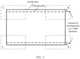
- an overhang region (a part of the anode plate beyond the cathode plate in length and width directions) is usually designed, that is, an edge of the anode plate and an edge of the cathode plate are not aligned, but there is an amount of misalignment. If the amount of misalignment of the anode plate relative to the cathode plate is excessively small, the foregoing lithium precipitation problem is likely to occur. Therefore, it is necessary to detect the amount of misalignment during production inspection of lithium batteries.
- CN 112 330 623 A relates to a method for detecting the alignment of the pole pieces of the battery cell pole group.
- Xie Fang et al. "Research on the Coordinate Attention Mechanism Fuse in a YOLOv5 Deep Learning Detector for the SAR Ship Detection Task", SENSORS, vol. 22, no. 9, 28 April 2022 (2022-04-28), page 3370, ISSN: 1424-8220, DOI: 10.3390/s22093370 discloses the fusion of two lightweight deep learning models which are the Coordinate Attention mechanism module and the YOLOv5 detector.
- this application provides a battery cell electrode plate detection method and apparatus, and an electronic device to detect an amount of misalignment between a cathode plate and an anode plate.
- an embodiment of this application provides a battery cell electrode plate detection method, including:
- the battery cell electrode plate detection method provided in this embodiment of this application, feature extraction is performed on the to-be-detected battery cell electrode plate image, then electrode plate detection is performed based on the extracted electrode plate feature, and then the amount of misalignment between the anode plate and the cathode plate is determined based on the position information of the anode plate and the cathode plate in the electrode plate detection result. In this way, the amount of misalignment between the anode plate and the cathode plate can be detected.
- the feature extraction process can extract an effective feature, thereby improving accuracy of the electrode plate detection result and further improving accuracy of an amount-of-misalignment detection result.
- the feature extraction process can reduce data dimensionality, and therefore can also improve detection efficiency.
- an attention mechanism is added to the feature extraction process to extract the channel attention feature including the embedded position information, the position information of the electrode plates and a feature channel relationship in the battery cell electrode plate image can be captured. This can effectively improve effectiveness of the extracted feature, further improve accuracy of the electrode plate detection result, and further improve accuracy of the amount-of-misalignment detection result.
- the performing feature extraction on a to-be-detected battery cell electrode plate image to obtain an electrode plate feature includes:
- the plurality of convolution operations and at least one attention operation are performed to extract the first feature, then multi-scale fusion is performed on the first feature to obtain the second feature, and then feature fusion is further performed on the second feature.
- the attention operation is used before feature fusion, a feature extraction effect at an early feature extraction stage can be improved, and further, better results can be obtained in subsequent feature fusion and target prediction.
- the performing a plurality of convolution operations and at least one attention operation on the to-be-detected battery cell electrode plate image to obtain a first feature includes:
- the slicing operation, followed by the convolution operation may be performed on the battery cell electrode plate image to improve a receptive field of each extracted feature point, while reducing an amount of calculation and increasing a speed of feature extraction; and the plurality of convolution, batch normalization, activation, and cross-stage partial fusion operations may be performed on the initial feature to effectively extract a partial feature in a feature map, optimize gradient information in a backbone network, effectively enhance a learning capability of the network, and improve accuracy of the detection result while reducing the amount of calculation and memory costs.
- the performing a plurality of convolution, batch normalization, activation, and cross-stage partial fusion operations on the initial feature to obtain a target partial feature includes:
- the foregoing two attention operations may be performed to further improve the feature extraction effect.
- the performing feature fusion from deep to shallow and then from shallow to deep on the second feature to obtain the electrode plate feature includes:
- the feature fusion effect can be improved and a better electrode plate feature can be obtained.
- the attention operation includes:
- the foregoing attention operation may be used to capture both the position information and a long range dependency between channels and improve the feature extraction effect.
- the determining, based on the coordinates of the target vertex of each anode plate and the coordinates of the target vertex of each cathode plate, the amount of misalignment between the anode plate and the cathode plate includes:
- the battery cell electrode plate image is obtained by photographing an edge region of a target battery cell, and the amount of misalignment between the anode plate and cathode plate is determined based on electrode plate detection results corresponding to a plurality of battery cell electrode plate images; and the method further includes: detecting, based on a determined amount of misalignment between an anode plate and a cathode plate, whether the target battery cell is qualified.
- the determined amount of misalignment between the anode plate and the cathode plate includes an amount of misalignment between each cathode plate and each of two adjacent anode plates in each electrode plate detection result; and the detecting, based on a determined amount of misalignment between an anode plate and a cathode plate, whether the target battery cell is qualified includes: if there is an amount of misalignment less than or equal to a first threshold among the determined amounts of misalignment corresponding to each cathode plate, determining that the target battery cell is unqualified.
- the method further includes:
- the electrode plate detection result is obtained by using an electrode plate detection model, where the electrode plate detection model is used to perform electrode plate detection based on the obtained electrode plate feature after feature extraction is performed on the battery cell electrode plate image, and output the electrode plate detection result; and the electrode plate detection model is obtained through training by using the following training method:
- the electrode plate detection model may be trained; and image preprocessing and data enhancement may be performed to improve reliability and richness of training samples and further improve a training effect.
- the image preprocessing includes filtering and/or contrast enhancement.
- the training an initial electrode plate detection model by using the sample data set, to obtain the electrode plate detection model includes:
- a model training speed may be effectively increased by using the validation set.
- an embodiment of this application provides a battery cell electrode plate detection apparatus, including:
- the performing feature extraction on a to-be-detected battery cell electrode plate image to obtain an electrode plate feature includes:
- the performing a plurality of convolution operations and at least one attention operation on the to-be-detected battery cell electrode plate image to obtain a first feature includes:
- the performing a plurality of convolution, batch normalization, activation, and cross-stage partial fusion operations on the initial feature to obtain a target partial feature includes:
- the performing feature fusion from deep to shallow and then from shallow to deep on the second feature to obtain the electrode plate feature includes:
- the attention operation includes:
- the position information includes coordinates of a central point of a detection box and a width and height of the detection box; and the determining an amount of misalignment between the anode plate and the cathode plate based on the position information of the anode plate and the cathode plate in the electrode plate detection result includes:
- the determining, based on the coordinates of the target vertex of each anode plate and the coordinates of the target vertex of each cathode plate, the amount of misalignment between the anode plate and the cathode plate includes:
- the battery cell electrode plate image is obtained by photographing an edge region of a target battery cell, and the amount of misalignment between the anode plate and cathode plate is determined based on electrode plate detection results corresponding to a plurality of battery cell electrode plate images; and the detection module is further configured to: the detection module is configured to detect, based on a determined amount of misalignment between an anode plate and a cathode plate, whether the target battery cell is qualified.
- the determined amount of misalignment between the anode plate and the cathode plate includes an amount of misalignment between each cathode plate and each of two adjacent anode plates in each electrode plate detection result; and the detecting, based on a determined amount of misalignment between an anode plate and a cathode plate, whether the target battery cell is qualified includes: if there is an amount of misalignment less than or equal to a first threshold among the determined amounts of misalignment corresponding to each cathode plate, determining that the target battery cell is unqualified.
- the detection module is further configured to:
- the electrode plate detection result is obtained by using an electrode plate detection model, where the electrode plate detection model is used to perform electrode plate detection based on the obtained electrode plate feature after feature extraction is performed on the battery cell electrode plate image, and output the electrode plate detection result; and the electrode plate detection model is obtained through training by using the following training method:
- the image preprocessing includes filtering and/or contrast enhancement.
- the data enhancement includes at least one of the following: random flipping, scale variation, image translation, and noise addition.
- the training an initial electrode plate detection model by using the sample data set, to obtain the electrode plate detection model includes:
- an embodiment of this application provides an electronic device, including a memory and a processor, where the memory is configured to store a computer program; and the processor is configured to perform the method according to the first aspect or any implementation of the first aspect when the computer program is invoked.
- an embodiment of this application provides a computer-readable storage medium, where the computer-readable storage medium stores a computer program, and when the computer program is executed by a processor, the method according to the first aspect or any implementation of the first aspect is implemented.
- the application provides a computer program product, where when the computer program product runs on an electronic device, the electronic device is enabled to perform the method according to any implementation of the first aspect.
- an embodiment of this application provides a system-on-chip, including a processor, where the processor is coupled to a memory, and the processor executes a computer program stored in the memory, to implement the method according to the first aspect or any implementation of the first aspect.
- the system-on-chip may be a single chip or a chip module including a plurality of chips.
- Naming or numbering of steps in this application does not mean that steps in a method process must be performed in a time or logical sequence indicated by the naming or numbering. An execution sequence of the named or numbered process steps may be changed according to a technical objective to be achieved, provided that same or similar technical effects can be achieved.
- the disclosed apparatus/device and method may be implemented in other manners.
- the described apparatus/device embodiment is merely an example.
- the module or unit division is merely logical function division and may be other division in an actual implementation.
- a plurality of units or components may be combined or integrated into another system, or some features may be ignored or may not be performed.
- the displayed or discussed mutual couplings or direct couplings or communications connections may be implemented by using some interfaces.
- the indirect couplings or communications connections between apparatuses or units may be implemented in electrical, mechanical, or other forms.
- A/B may represent A or B.
- the term "and/or” in this application is only an association relationship for describing associated objects and represents that three relationships may exist.
- a and/or B may represent the following three cases: Only A exists, both A and B exist, and only B exists, where A and B may be in a singular or plural form.
- a plurality of means two or more, unless otherwise stated.
- the term "at least one of the following items” or an expression similar to the term indicates any combination of the items, and includes a single item or any combination of a plurality of items.
- at least one of a, b, or c may indicate: a, b, c, a-b, a-c, b-c, or a-b-c, where a, b, and c may be in a singular or plural form.
- the term “if” may be interpreted as “when”, “once”, “in response to determining”, or “in response to detecting”, depending on the context.
- the phrase “if determining” or “if detecting [the described condition or event]” may be interpreted as “once determining”, “in response to determining”, “once detecting [the described condition or event]”, or “in response to detecting [the described condition or event]”, depending on the context.
- references to "an embodiment”, “some embodiments”, or the like described in this specification of this application means that one or more embodiments of this application include a specific feature, structure, or characteristic described with reference to the embodiment. Therefore, expressions such as “in an embodiment”, “in some embodiments”, “in some other embodiments”, and “in some different embodiments” appearing in different places in this specification do not necessarily indicate reference to a same embodiment, but mean “one or more but not all embodiments", unless otherwise specified in another way.
- an overhang design is usually used, so that a part of an anode plate is beyond a cathode plate in length and width directions, that is, there is an amount of misalignment between an edge of the anode plate and an edge of the cathode plate.
- the battery cell is mainly formed by winding or stacking the anode plate and the cathode plate.
- the anode plate and the cathode plate are separated by a separator.
- the inventor finds that during production of the battery cell, when the battery cell is wound or folded, the amount of misalignment between the electrode plates in the battery cell is likely to deviate in the width direction. However, if the amount of misalignment between the anode plate and the cathode plate is excessively small, the foregoing lithium precipitation problem is likely to occur. Therefore, it is necessary to detect the amount of misalignment during production inspection of lithium batteries.
- X-rays are used to capture X-ray images of an anode plate and a cathode plate in the battery cell
- a conventional image algorithm or a deep learning detection method is used to locate cathode and anode targets (that is, the anode plate and the cathode plate), and then the amount of misalignment between the anode plate and the cathode plate of the battery cell is calculated.
- this detection algorithm is poorly resistant to interference and prone to missed detection and inaccurate positioning problems.
- an attention mechanism can help find a region of real interest in a target detection process, filter out useless information, and effectively improve accuracy of target detection.
- a spatial structure of the cathode and anode targets is important in detection of the cathode and anode targets in the battery cell, and paying attention to position information can help extract a more effective feature.
- a multi-channel mechanism may be used to extract a richer feature, and paying attention to channel information can help extract a more effective feature.
- the inventor after in-depth research, proposes a battery cell electrode plate detection solution, where feature extraction is performed on a battery cell electrode plate image, position information of an anode plate and a cathode plate in the battery cell electrode plate image is detected based on an extracted electrode plate feature, and then an amount of misalignment between the anode plate and the cathode plate is determined; in addition, an attention mechanism is added to the feature extraction process to extract a channel attention feature embedded with the position information, so as to obtain a more effective feature and further improve accuracy of a detection result.
- the feature extraction process can extract an effective feature, thereby improving accuracy of the electrode plate detection result and further improving accuracy of an amount-of-misalignment detection result.
- the feature extraction process can reduce data dimensionality, and therefore can also improve detection efficiency. Because the attention mechanism is added to the feature extraction process to extract the channel attention feature including the embedded position information, the position information of the electrode plates and a feature channel relationship in the battery cell electrode plate image can be captured. This can effectively improve effectiveness of the extracted feature and further improve accuracy of the amount-of-misalignment detection result.
- a battery cell electrode plate detection method provided in an embodiment of this application may be used to detect various battery cells with an overhang design.
- the following uses a battery cell structure shown in FIG. 1 as an example for description.
- FIG. 1 is a schematic structural diagram of a front view of a battery cell.
- the battery cell is a winding battery cell.
- the battery cell is mainly formed by winding an anode plate and a cathode plate, and the anode plate and the cathode plate are separated by a separator.
- FIG. 3 is a schematic structural diagram of a top view of the battery cell shown in FIG. 1 . As shown in FIG. 3 , in a height direction of the battery cell, that is, a width direction of an electrode plate, two ends of the anode plate exceed the cathode plate to form an overhang region, and there is an amount of misalignment between the anode plate and the cathode plate.
- a perspective imaging device such as an X-ray imaging device or a computed tomography (Computed Tomography, CT) device may be used to capture an image of the battery cell to obtain a battery cell electrode plate image.
- CT computed tomography
- FIG. 2 is a schematic diagram of a position relationship between the anode plate and the cathode plate in a battery cell electrode plate image corresponding to one edge region. As shown in FIG. 2 , the anode plate and the cathode plate are arranged alternately, and there is an amount of misalignment between the anode plate and the cathode plate.
- FIG. 2 is only an example for showing the position relationship between the anode plate and the cathode plate in the photographed battery cell electrode plate image and does not represent an actual battery cell electrode plate image.
- the number of winding layers of the anode plate and the number of winding layers of the cathode plate shown in FIG. 1 and FIG. 2 are also only examples, both for indicating the position relationship between the anode plate and the cathode plate only.
- a battery cell may include more winding layers than shown in the figure.
- the two ends in the height direction of the battery cell may be photographed separately, and battery cell electrode plate images are obtained by photographing four edge regions A, B, C, and D located at corners of the battery cell.
- one or more battery cell electrode plate images may be captured; or one or more images may be captured for the entire battery cell in a photographing direction shown in FIG. 1 , and then the captured images are cropped to obtain a plurality of battery cell electrode plate images corresponding to each edge region.
- the four regions A, B, C, and D may be mainly photographed as described above to obtain battery cell electrode plate images to improve detection efficiency; or other regions of the battery cell may be photographed, for example, X-rays may be emitted in the width direction of the battery cell, and the two ends in the height direction of the battery cell may be photographed separately; or two sides in the width direction of the battery cell may be photographed to obtain a more comprehensive battery cell electrode plate image.
- a manner of capturing battery cell electrode plate images and a quantity of captured images are not particularly limited in this embodiment of this application. For ease of description, an example in which four battery cell electrode plate images are obtained by separately photographing the four regions A, B, C, and D is subsequently used as an example for description in this embodiment of this application.
- the amount of misalignment between the cathode plate and the anode plate may be detected based on the battery cell electrode plate image.
- the battery cell electrode plate image may be first cropped to obtain a region of interest (Region of Interest, ROI), and then preprocessing such as filtering and/or contrast enhancement may be performed on the ROI to obtain a battery cell electrode plate image in which the cathode plate and the anode plate can be clearly distinguished. Then detection may be performed on these to-be-detected battery cell electrode plate images to determine the amount of misalignment between the anode plate and the cathode plate of the battery cell. The following describes the detection process in detail.
- ROI region of interest
- preprocessing such as filtering and/or contrast enhancement
- FIG. 4 is a schematic flowchart of a battery cell electrode plate detection method according to an embodiment of this application. As shown in FIG. 4 , the method may include the following steps.
- a neural network such as a deep neural network or a convolutional neural network may be used, to improve a feature extraction effect.
- a multi-channel mechanism may be used to extract a richer feature.
- an attention mechanism may be added to the neural network to capture position information of electrode plates and a feature channel relationship in the battery cell electrode plate image and obtain the channel attention feature embedded with the position information, so as to obtain a more effective feature.
- a specific attention mechanism used may be a convolutional block attention module (Convolutional Block Attention Module, CBAM) or coordinate attention (Coordinate Attention, CA).
- CBAM Convolutional Block Attention Module
- CA Coordinat Attention
- the CBAM attention mechanism introduces position information by performing global pooling on a channel. In this way, partial spatial structure information can be captured.
- the CA attention mechanism decomposes channel attention into two one-dimensional feature encoding processes that aggregate features along two spatial directions respectively. In this way, a remote dependency can be captured along one spatial direction, while accurate position information along another spatial direction is reserved.
- Feature maps generated thereby are encoded as a pair of direction-aware and position-sensitive feature maps respectively, and the feature maps are both applied to an input feature map. Therefore, a feature representation of a target to be detected is enhanced.
- the CA attention mechanism is used to improve the feature extraction effect, and this is also used as an example for description subsequently.
- FIG. 5 is a schematic structural diagram of a CA attention mechanism according to an embodiment of this application. As shown in FIG. 5 , the CA attention mechanism may include the following steps.
- Avg Pool global average pooling
- a size of the input feature map is C ⁇ H ⁇ W, where C represents the number of channels, H represents a height, and W represents a width.
- Pooling kernels are (1, W) and (H, 1) respectively. Sizes of the feature maps in the width direction and the height direction that are obtained after the global average pooling operation is performed are C ⁇ H ⁇ 1 and C ⁇ 1 ⁇ W respectively.
- the feature maps in the width direction and the height direction are concatenated (Concat) and fed into a shared convolution module whose convolution kernel is 1 ⁇ 1, so that a two-dimensional convolution (Conv2d) operation is performed to reduce dimensionality thereof to C/r of the original dimensionality and obtain a feature map with a size of C/r ⁇ 1 ⁇ (W+H).
- the feature map is fed into a Sigmoid activation function for non-linear (Non-linear) transformation, to obtain a C/r ⁇ 1 ⁇ (W+H) feature map f.
- the feature map f is decomposed into two separate tensors along a spatial dimension, and two-dimensional convolution (whose convolution kernel is 1 ⁇ 1) is performed on the tensors respectively to obtain a feature map Fh with a size of C ⁇ H ⁇ 1 and a feature map Fw with a size of C ⁇ 1 ⁇ W.
- an attention weight of the feature map in the height direction and an attention weight of the feature map in the width direction are obtained respectively.
- the obtained attention weight in the height direction and attention weight in the width direction of the input feature map are applied to the original input feature map, and a final feature map with attention weights in the width direction and the height direction are obtained through multiplicative weighting calculation.
- one or more attention operations may be performed during feature extraction.
- one or more CA attention modules may be embedded in the neural network, where the CA attention module may be embedded at any position in the neural network, and this is not particularly limited in this embodiment.
- electrode plate detection may be performed on the battery cell electrode plate image based on the extracted electrode plate feature by using a related target detection algorithm, to obtain the electrode plate detection result, where the electrode plate detection result may include position information of an anode plate and a cathode plate.
- a two-stage (two stage) target detection algorithm may be used, or a one-stage (one stage) target detection algorithm may be used, to increase a detection speed.
- the one-stage target detection algorithm may include a single shot multibox detector (Single Shot MultiBox Detector, SSD) algorithm, a YOLO algorithm, or the like.
- SSD Single Shot MultiBox Detector
- YOLO YOLO
- the electrode plate detection result may specifically include a detected type and position information of each detection box, where each detection box is used to represent an electrode plate, and the type of the detection box is used to indicate whether the electrode plate represented by the detection box is an anode plate or a cathode plate, that is, the type of the detection box may include an anode plate and a cathode plate. For example, 0 may be used to represent an anode plate and 1 may be used to represent a cathode plate.
- FIG. 6 is a schematic diagram of an electrode plate detection result.
- the electrode plate detection result may include a detection box b0 corresponding to each anode plate and a detection box b1 corresponding to each cathode plate in the battery cell electrode plate image, and each detection box has corresponding position information (not shown).
- the position information of the detection box may include coordinates of a central point of the detection box and a width and height of the detection box.
- the position information of the detection box may alternatively be indicated in other manners.
- coordinates of other positions in the detection box may also be used to indicate a location of the detection box. This is not particularly limited in this embodiment.
- the position information of the detection box including the coordinates of the central point and the width and height of the detection box is used as an example for description subsequently.
- the amount of misalignment between the cathode plate and the anode plate may be determined after the electrode plate detection result is obtained.
- FIG. 7 is a schematic flowchart of a method for determining an amount of misalignment based on an electrode plate detection result according to an embodiment of this application. As shown in FIG. 7 , the method may include the following steps.
- S132 Determine coordinates of a target vertex of each cathode plate based on coordinates of a central point of a detection box of each cathode plate and a width and height of the detection box of each cathode plate in the electrode plate detection result.
- S133 Determine, based on the coordinates of the target vertex of each anode plate and the coordinates of the target vertex of each cathode plate, the amount of misalignment between the anode plate and the cathode plate.
- the target vertex may be an upper left vertex or an upper right vertex of the detection box.
- Vx, Vy represents the coordinates of the upper left vertex of the detection box
- Cx, Cy represents the coordinates of the central point of the detection box
- w represents the width of the detection box
- h represents the height of the detection box.
- the position information of the detection box in the electrode plate detection result may also include the coordinates of the target vertex of the detection box.
- the amount of misalignment between the anode plate and the cathode plate may be determined directly based on the coordinates of the target vertex of each anode plate and the coordinates of the target vertex of each cathode plate.
- a cathode plate adjacent to each anode plate or an anode plate adjacent to each cathode plate may be determined based on the coordinates of the target vertex of each anode plate and the coordinates of the target vertex of each cathode plate, and then an amount of misalignment between each anode plate and the adjacent cathode plate or an amount of misalignment between each cathode plate and the adjacent anode plate may be determined.
- anode plate 1 on the left it may be determined, based on horizontal coordinates of the coordinates of the target vertices of each cathode plate and each anode plate, that a cathode plate adjacent to the anode plate 1 is a cathode plate 2, and then an amount of misalignment between the anode plate 1 and the cathode plate 2 may be calculated based on vertical coordinates of the coordinates of the target vertices of the anode plate 1 and the cathode plate 2.
- determining the amount of misalignment between the cathode plate and the anode plate based on the coordinates of the target vertex of each cathode plate and the coordinates of the target vertex of each anode plate may be implemented by the following steps.
- the position relationship may be indicated by sequence numbers obtained by sorting each anode plate and each cathode plate.
- sequence numbers obtained by sorting each anode plate and each cathode plate For example, seven electrode plates are included in FIG. 6 , and a sequence number of each electrode plate may be obtained by sorting each electrode plate in the horizontal coordinate direction based on the horizontal coordinate of the coordinates of the target vertex of each electrode plate, where sequence numbers of the anode plates are 1, 3, 5, and 7 sequentially; and sequence numbers of the cathode plates are 2, 4, and 6 sequentially.
- each cathode plate determine, based on a vertical coordinate of the coordinates of the target vertex of the cathode plate and vertical coordinates of coordinates of target vertices of two anode plates adjacent to the cathode plate, an amount of misalignment between the cathode plate and each of the two adjacent anode plates.
- O12 represents the amount of misalignment between the cathode plate 2 and the anode plate 1
- O32 represents the amount of misalignment between the cathode plate 2 and the anode plate 3
- Vy1 represents a vertical coordinate of an upper left vertex of the anode plate 1
- Vy2 represents a vertical coordinate of an upper left vertex of the cathode plate 2
- Vy3 represents a vertical coordinate of an upper left vertex of the anode plate 3.
- amounts of misalignment between other cathode plates and adjacent anode plates may be obtained, and each cathode plate corresponds to two amounts of misalignment.
- six amounts of misalignment may be obtained based on the electrode plate detection result shown in FIG. 6 .
- the amount of misalignment between each anode plate and the adjacent cathode plate may alternatively be determined by using the anode plate as a benchmark, where two anode plates located at two ends have one adjacent cathode plate, and the other anode plates have two adjacent cathode plates.
- a specific determining process is similar to the foregoing process of determining the amount of misalignment by using the cathode plate as a benchmark. Details are not described herein.
- the feature extraction process can extract an effective feature, thereby improving accuracy of the electrode plate detection result and further improving accuracy of an amount-of-misalignment detection result.
- the feature extraction process can reduce data dimensionality, and therefore can also improve detection efficiency. Because the attention mechanism is added to the feature extraction process to extract the channel attention feature including the embedded position information, the position information of the electrode plates and the feature channel relationship in the battery cell electrode plate image can be captured. This can effectively improve effectiveness of the extracted feature, further improve accuracy of the electrode plate detection result, and further improve accuracy of the amount-of-misalignment detection result.
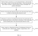
- the method may further include step S140: Detect, based on a determined amount of misalignment between an anode plate and a cathode plate, whether a target battery cell is qualified.
- the amount of misalignment between the anode plate and the cathode plate of the battery cell is determined, it is possible to determine whether the determined amount of misalignment meets a requirement, and further determine whether the battery cell (that is, the target battery cell) is qualified.
- Whether the target battery cell is qualified may be determined based on an amount-of-misalignment detection result corresponding to one battery cell electrode plate image of the target battery cell, and when an amount of misalignment in the amount-of-misalignment detection result corresponding to the battery cell electrode plate image does not meet the requirement, it may be determined that the target battery cell is unqualified.
- whether the target battery cell is qualified may be determined based on amount-of-misalignment detection results corresponding to a plurality of battery cell electrode plate images of the target battery cell, that is, the amount of misalignment between the anode plate and the cathode plate as a basis for determining whether the target battery cell is qualified is determined based on electrode plate detection results corresponding to the plurality of battery cell electrode plate images, where the plurality of battery cell electrode plate images may be obtained by photographing a plurality of edge regions of the target battery cell.
- the plurality of battery cell electrode plate images may include the four battery cell electrode plate images obtained by photographing the four regions A, B, C, and D, as described in the embodiment shown in FIG. 3 ; and for each battery cell electrode plate image, an amount-of-misalignment detection result corresponding to the battery cell electrode plate image may be determined by using the foregoing steps S110 to S130.
- each determined amount of misalignment meets the requirement. If there is an amount of misalignment that does not meet the requirement, it may be determined that the target battery cell is unqualified. If each amount of misalignment meets the requirement, it may be determined that the target battery cell is qualified.
- detecting whether the target battery cell is qualified may specifically include the following steps.
- the first threshold T1 may be a lower limit for the amount of misalignment between the anode plate and the cathode plate in an overhang design of the battery cell. If the determined amount of misalignment is less than the first threshold T1, it indicates that the amount of misalignment is excessively small, and a lithium precipitation problem is likely to occur. Therefore, it can be determined that the target battery cell is unqualified.
- the second threshold T2 may be an upper limit for the amount of misalignment between the anode plate and the cathode plate in the overhang design of the battery cell.
- the second threshold T2 may be an upper limit for the amount of misalignment between the anode plate and the cathode plate in the overhang design of the battery cell.
- the amounts of misalignment corresponding to each cathode plate are all greater than the first threshold T1 and less than the second threshold T2, it may be determined that the target battery cell is qualified.
- the target battery cell is qualified herein means that the amount of misalignment between the cathode plate and the anode plate of the target battery cell conforms to the overhang design, that is, the target battery cell is qualified in terms of amount-of-misalignment detection, but it does not mean that the target battery cell is also qualified in other detection items.
- the target battery cell is unqualified.
- part of the steps in FIG. 9 may be performed. For example, only the determining based on the first threshold T1 may be performed to detect an unqualified battery cell in which an amount of misalignment between a cathode plate and an anode plate is excessively small; or step S 142 may not be performed, only a battery cell with an unqualified amount of misalignment between a cathode plate and an anode plate is detected, and after detection of other detection items of the battery cell is completed, if it is determined that detection results of all the detection items meet requirements, the battery cell is determined as qualified.
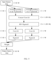
- the YOLO algorithm may be used to extract the electrode plate feature, where the YOLO algorithm may include a backbone (Backbone) network, a neck (Neck) network, and a head prediction (Head Prediction) network, where the backbone network is used for feature extraction, the neck network is used for feature fusion based on a feature extracted by the backbone network, and the head prediction network is used to predict, based on a feature fusion result of the neck network, a detection box corresponding to a target.
- Backbone Backbone
- neck Neck
- Head Prediction head prediction
- a YOLOv4 or YOLOv5 algorithm may be used specifically, where the backbone network and the neck network may include a plurality of convolution modules, a spatial pyramid pooling (Spatial Pyramid Pooling, SPP) module, a feature pyramid network (Feature Pyramid Network, FPN) module, and a path aggregation network (Path Aggregation Network, PAN) module.
- SPP spatial Pyramid Pooling
- FPN feature Pyramid Network
- PAN Path aggregation network
- the foregoing attention module may be added to the backbone network to improve a feature extraction effect at an early feature extraction stage, and further, better results can be obtained in subsequent feature fusion and target prediction.
- One or more attention modules may be added.
- the convolution module is configured to perform a convolution operation on the input feature map to extract a partial feature.
- the SPP module is configured to perform multi-scale pooling on the input feature map to extract spatial feature information of different sizes and concatenate all outputs to implement fusion of the multi-scale feature information and improve robustness of the network in terms of spatial layout and object variability.
- the SPP module can convert a feature map of any size into a feature map of a fixed size.
- the FPN module is configured to perform a feature fusion operation from deep to shallow on the feature extracted by the backbone network.
- the PAN module is configured to perform a feature fusion operation from shallow to deep on the feature fused by the FPN module.
- the FPN module can enhance semantic information and the PAN module can enhance positioning information, both of which can enable the model to obtain richer feature information.
- step S110 during extraction of the electrode plate feature, a plurality of convolution operations and at least one attention operation may be first performed on the to-be-detected battery cell electrode plate image by using the plurality of convolution modules and the added attention module, to obtain a first feature; then multi-scale feature fusion may be performed on the first feature by using the SPP module, to obtain a second feature; and then feature fusion from deep to shallow and then from shallow to deep may be performed on the second feature by using the FPN module and the PAN module, to obtain the electrode plate feature.
- a specific target detection algorithm that is, an electrode plate detection algorithm
- the YOLOv5 algorithm includes a plurality of versions, and any version of the YOLOv5 algorithm may be used in this embodiment.
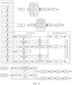
- FIG. 11 is a schematic diagram of a network structure of an electrode plate detection algorithm according to an embodiment of this application.
- the electrode plate detection algorithm is specifically the YOLOv5 algorithm
- the backbone network in this algorithm model may specifically include a focus module, a plurality of CBS modules, a plurality of cross-stage partial (Cross Stage Partial, CSP) modules, and an SPP module.
- the foregoing attention module may be added before the SPP module.
- the focus module is configured to perform a slicing (Silce) operation on the input image, that is, an input image channel is expanded to four times the original one by performing sampling at intervals of one pixel in horizontal and vertical coordinate directions on the original image. Then the slices are concatenated (Concat), and then one convolution operation is performed by using the CBS module, to obtain a downsampled feature map, to improve a receptive field of each feature point, while reducing the amount of calculation and increasing a feature extraction speed.
- a slicing (Silce) operation on the input image, that is, an input image channel is expanded to four times the original one by performing sampling at intervals of one pixel in horizontal and vertical coordinate directions on the original image. Then the slices are concatenated (Concat), and then one convolution operation is performed by using the CBS module, to obtain a downsampled feature map, to improve a receptive field of each feature point, while reducing the amount of calculation and increasing a feature extraction speed.
- the CBS module includes a convolution (Conv) module, a batch normalization (BN) module, and a SiLu activation module, and is configured to perform a standard convolution operation on the input feature map to extract a partial feature in the feature map.
- Conv convolution
- BN batch normalization
- SiLu activation module SiLu activation module
- the CSP module divides the input feature map into two branches. One branch first passes through the CBS module and then passes a plurality of residual components (Res unit), and then one convolution operation is performed. Then the two branches are concatenated (Concat), then a BN operation and one SiLu activation operation are performed, and finally the downsampled feature map is obtained by using one CBS module.
- the CSP module can optimize gradient information in the backbone network, thereby effectively enhancing a learning capability of the network and improving accuracy of the detection result while reducing the amount of calculation and memory costs.
- the SPP module is configured to pass the input feature map through the CBS module first, then perform a maximum pooling (MaxPool) operation by using pooling kernels of different sizes, then perform multi-scale feature fusion by using the Concat module, and then restore an output to an initial input size by using one CBS module.
- MaxPool maximum pooling
- the CBS module may also be replaced with a CBL module, and a main difference between the CBL module and the CBS module is that the activation module uses a Leaky relu activation function.
- a slicing operation and then a convolution operation may be first performed on the to-be-detected battery cell electrode plate image by using the focus module, to obtain an initial feature; then a plurality of convolution, batch normalization, activation, and cross-stage partial fusion operations are performed on the initial feature by using the plurality of CBS modules and the plurality of CSP modules, to obtain a target partial feature; and then an attention operation is performed on the target partial feature by using the attention module, to obtain the first feature.
- a specific version used for the electrode plate detection algorithm is YOLOv5s, to improve accuracy of the detection result and increase the detection speed while saving storage space.
- the YOLOv5s algorithm is used as an example for description.
- the backbone network may specifically include four CBS modules (CBS11 module, CBS12 module, CBS13 module, and CBS14 module), three CSP modules (including one CSP1_1 module and two CSP1_3 modules), and one SPP module.
- CBS11 module CBS11 module
- CBS12 module CBS13 module
- CBS14 module CBS14 module
- CSP modules including one CSP1_1 module and two CSP1_3 modules
- SPP module SPP module.
- "X" in the CSP1_X module denotes a quantity of residual components included in the CSP module.
- one attention module may be connected to an output end of each CSP module.
- three attention modules may be included: a CA1 module, a CA2 module, and a CA3 module.
- convolution, batch normalization, and activation processing may be first performed on the initial feature by using the CBS11 module, to obtain a first convolutional feature; then a cross-stage partial fusion operation is performed on the first convolutional feature by using the CSP1_1 module, to obtain a first partially fused feature; and then an attention operation is performed on the first partially fused feature by using the CA1 module, to obtain a first attention-fused feature.
- convolution, batch normalization, and activation processing are performed on the second attention-fused feature by using the CBS13 module, to obtain a third convolutional feature; then a cross-stage partial fusion operation is performed on the third convolutional feature by using the second CSP1_3 module, to obtain a target partially fused feature; and then an attention operation is performed on the target partially fused feature by using the CA3 module, to obtain the first feature.
- convolution, batch normalization, and activation processing are performed on the first feature by using the CBS14 module, to obtain a fourth convolutional feature, and then multi-scale feature fusion is performed on the fourth convolutional feature by using the SPP module, to obtain the second feature.
- the attention module may use the foregoing CBAM attention mechanism or use the CA attention mechanism, to capture both the position information and a long range dependency between channels and improve the feature extraction effect.
- the CA attention mechanism is used as an example for description.
- the foregoing algorithm principle shown in FIG. 5 may be used to obtain the attention weight in the width direction and the attention weight in the height direction of the input feature map; and then multiplicative weighting calculation is performed based on the obtained attention weights and the feature map to obtain a feature map with the attention weights in the width direction and the height direction.
- the neck network may specifically include five CSP modules (all of which are CSP2_1 modules), four CBS modules (CBS21 module, CBS22 module, CBS23 module, and CBS24 module), two upsampling modules, and four Concat modules.
- the CSP2_X module in the neck network is slightly different from the CSP module in the backbone network, and a main difference is that the residual components in the CSP module of the backbone network are replaced with 2 ⁇ X CBS modules.
- the SPP module in the backbone network is connected to a first input end of the first Concat module through the first CSP2_1 module, the CBS21 module, and the first upsampling module; and a second input end of the first Concat module is connected between the second CSP1_3 module and the CBS4 module in the backbone network.
- An output end of the first Concat module is connected to a first input end of the second Concat module through the second CSP2_1 module, the CBS22 module, and the second upsampling module; and a second input end of the second Concat module is connected between the first CSP1_3 module and the CBS13 module in the backbone network.
- An output end of the second Concat module outputs a first-scale feature map to the head prediction network through the third CSP2_1 module.
- An output end of the second Concat module is connected to a first input end of the third Concat module through the third CSP2_1 module and the CBS23 module; and a second input end of the third Concat module is connected between the CBS22 module and the second upsampling module.
- An output end of the third Concat module outputs a second-scale feature map to the head prediction network through the fourth CSP2_1 module.
- An output end of the third Concat module is connected to a first input end of the fourth Concat module through the fourth CSP2_1 module and the CBS24 module; and a second input end of the fourth Concat module is connected between the CBS21 and the first upsampling module.
- An output end of the fourth Concat module outputs a third-scale feature map to the head prediction network through the fifth CSP2_1 module.
- the second input end of the first Concat module may be connected before or after the CA3 module in the backbone network; and similarly, the second input end of the second Concat module may be connected before or after the CA2 module in the backbone network.
- the second input end of the first Concat module is connected after the CA3 module, and the second input end of the second Concat module is connected after the CA2 module to improve accuracy of the electrode plate detection result.
- obtaining the electrode plate feature based on the second feature may be implemented by the following steps.
- convolution and upsampling processing are performed on the second feature by using the first CSP2_1 module, the CBS21 module, the first upsampling module, and the first Concat module, followed by feature fusion with the first feature output by the CA3 module, to obtain an intermediate fused feature.
- feature fusion is performed based on the first-scale electrode plate feature and the intermediate fused feature by using the CBS23 module, the third Concat module, and the fourth CSP2_1 module, to generate a second-scale electrode plate feature.
- feature fusion is performed based on the second-scale electrode plate feature and the second feature by using the CBS24 module, the fourth Concat module, and the fifth CSP2_1 module, to generate a third-scale electrode plate feature.
- the head prediction network may specifically include three detection heads for outputting electrode plate detection results, where each detection head is connected to three output ends of the neck network through one convolution module and configured to receive electrode plate features at different scales, to detect target objects of different sizes based on the electrode plate features at different scales.
- the electrode plate detection result output by the head prediction network may include the detected type and position information of each detection box.
- the type of the detection box may include the anode plate and the cathode plate; and the position information of the detection box may include the coordinates of the central point of the detection box and the width and height of the detection box.
- the foregoing target detection algorithm (such as the YOLO algorithm) may be used to pre-train an electrode plate detection model, then the to-be-detected battery cell electrode plate image is input into the electrode plate detection model, and after feature extraction is performed on the input battery cell electrode plate image by using the electrode plate detection model, electrode plate detection is performed based on the obtained electrode plate feature to obtain the electrode plate detection result.
- the foregoing target detection algorithm such as the YOLO algorithm
- the electrode plate detection module may be obtained through training by using the method shown in FIG. 12 .
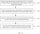
- the method for training the electrode plate detection model may include the following steps.
- S210 Perform image preprocessing and data enhancement on a plurality of obtained battery cell electrode plate sample images to obtain a target sample image set, where the target sample image set includes a plurality of target sample images.
- the battery cell electrode plate sample images may be captured by photographing a plurality of battery cells by using an X-ray device in the manners shown in FIG. 1 and FIG. 3 .
- image preprocessing may be performed to obtain preprocessed images to enhance definition of the battery cell electrode plate sample images.
- the image preprocessing may include filtering, contrast enhancement, and/or other preprocessing operations.
- data enhancement may be performed on the preprocessed images to obtain target sample images to increase a quantity of samples and enhance a generalization capability of the model.
- the data enhancement may include at least one of the following processing: random flipping, scale variation, image translation, noise addition, and the like.
- S220 Label the anode plate and the cathode plate in each target sample image to generate label information of each target sample image.
- a LabelImg tool may be used to label the anode plate and the cathode plate in each target sample image to generate the label information of each target sample image, where the label information may include the types and position information of the electrode plates, and the electrode plates may be represented by labeled detection boxes.
- each target sample image and its corresponding label information are combined to form a sample, and various samples are combined to form a sample data set.
- the sample data set may be used to train the initial electrode plate detection model to obtain the electrode plate detection model.
- the initial electrode plate detection model may use various target detection algorithms described above.
- YOLOv5s is used as an example for description subsequently.
- the sample data set may be divided into a training set and a test set, and samples in the training set are input into an initial multi-level feature extraction network model for training, so that a preliminary electrode plate detection model can be established; then the test set and a preset loss function are used to evaluate the established preliminary electrode plate detection model, and network parameters of the electrode plate detection model are modified based on an evaluation result by using an optimizer. The foregoing evaluation steps are repeated until the modified electrode plate detection model meets evaluation requirements.
- the electrode plate detection model that meets the evaluation requirements is a final established electrode plate detection model.
- the sample data set when the sample data set is used to train the initial electrode plate detection model, the sample data set may be first divided into a training set, a validation set, and a test set; then the initial electrode plate detection model is trained by using the training set, and during the training, hyperparameters are adjusted by using the validation set, until the model converges or reaches the maximum number of training epochs, to obtain the trained initial electrode plate detection model; and finally, after model evaluation is performed on the trained initial electrode plate detection model by using the test set, the electrode plate detection model is generated.
- the model includes model parameters and hyperparameters, where the model parameters include internal variables obtained through learning, such as weights, and the hyperparameters include the number of network layers, the number of network nodes, the maximum number of training epochs (epoch), a learning rate, and the like.
- the training set may be used to adjust the model parameters of the model
- the validation set may be used to adjust the hyperparameters of the model.
- a set of hyperparameters may be determined first, and then the initial electrode plate detection model is trained by using the training set and validated by using the validation set, and if an effect is poor, the hyperparameters may be adjusted; then the training set is used again for training and then the validation set is used for validation, and if an effect is poor, the hyperparameters continue to be adjusted; and this process is repeated cyclically for a plurality of times until the model converges or reaches the maximum number of training epochs.
- a size of the input image may be 1504 ⁇ 1504, initial weights of the model may be randomly initialized, the number of samples in a single batch (batch-size) may be set to 16, the maximum number of training epochs (epoch) may be set to 350, the optimizer may be an adaptive moment estimation (Adam) optimizer, an initial learning rate (lr0) may be set to 0.001, a momentum parameter (momentum) may be 0.937, and a weight decay coefficient (weight_decay) may be 0.0005.
- Adam adaptive moment estimation
- mean average precision (mean Average Precision, mAP) may be used to evaluate the model, where mAP is a mean value of average precision (Average Precision, AP) of each type, and may be obtained by averaging AP of the anode plate and AP of the cathode plate.
- the AP may be determined based on an intersection-over-union (Intersection-over-Union, IoU).
- IoU is an overlap rate of a detection box predicted by the model and a detection box in the label information, that is, a ratio of an intersection of the two detection boxes to a union thereof. The larger the value is, the more accurate the position information in the prediction result is.
- a prediction result corresponding to the sample may be considered as correct; otherwise, the prediction result corresponding to the sample may be considered as incorrect.
- the AP may be determined based on correctness of a prediction result corresponding to each sample in the validation set.
- FIG. 13 shows variations of mAP at different IoU thresholds (from 0.5 to 0.95 with a step of 0.05) as the number of training epochs increases during the training.
- the electrode plate detection model is the YOLOv5s model.
- a curve A1 indicates variations of mAP corresponding to the electrode plate detection model without the CA attention mechanism (hereinafter referred to as a model 1), and a curve A2 indicates a result after the curve A1 is smoothed; and a curve B1 indicates variations of mAP corresponding to the electrode plate detection model after three CA attention modules are added (hereinafter referred to as a model 2), and a curve B2 indicates a result after the curve B1 is smoothed.
- a mAP value of the model 2 is apparently higher than a mAP value of the model 1.
- An experimental result shows that the electrode plate detection model with the addition of the CA attention mechanism can obtain a more accurate detection result.
- a battery cell electrode plate detection method can implement an electrode plate detection process by using the foregoing electrode plate detection algorithm model shown in FIG. 11 .
- the method may include the following steps.
- Step 1 Perform a slicing operation and then a convolution operation on a to-be-detected battery cell electrode plate image by using the focus module, to obtain an initial feature.
- Step 2 Perform convolution, batch normalization, and activation processing on the initial feature by using the CBS11 model, to obtain a first convolutional feature.
- Step 3 Perform a cross-stage partial fusion operation on the first convolutional feature by using the CSP1_1 module, to obtain a first partially fused feature.
- Step 4 Perform an attention operation on the first partially fused feature by using the CA1 module, to obtain a first attention-fused feature.
- Step 5 Perform convolution, batch normalization, and activation processing on the first attention-fused feature by using the CBS12 module, to obtain a second convolutional feature.
- Step 6 Perform a cross-stage partial fusion operation on the second convolutional feature by using the first CSP1_3 module, to obtain a second partially fused feature.
- Step 7 Perform an attention operation on the second partially fused feature by using the CA2 module, to obtain a second attention-fused feature.
- Step 8 Perform convolution, batch normalization, and activation processing on the second attention-fused feature by using the CBS13 module, to obtain a third convolutional feature.
- Step 9 Perform a cross-stage partial fusion operation on the third convolutional feature by using the second CSP1_3 module, to obtain a target partially fused feature.
- Step 10 Perform an attention operation on the target partial feature by using the CA3 module, to obtain a first feature.
- Step 11 Perform convolution, batch normalization, and activation processing on the first feature by using the CBS14 module, to obtain a fourth convolutional feature, and then perform multi-scale feature fusion on the fourth convolutional feature by using the SPP module, to obtain a second feature.
- Step 12 Perform a cross-stage partial fusion operation on the second feature by using the first CSP2_1 module, to obtain a third partially fused feature, and then perform convolution, batch normalization, and activation processing on the third partially fused feature by using the CBS21 module, to obtain a fifth convolutional feature.
- Step 13 Perform upsampling processing on the fifth convolutional feature by using the first upsampling module, and after obtaining a first upsampling result, perform feature fusion on the first upsampling result and the first feature by using the first Concat module, to obtain an intermediate fused feature.
- Step 14 Perform a cross-stage partial fusion operation on the intermediate fused feature by using the second CSP2_1 module, to obtain a fourth partially fused feature, and then perform convolution, batch normalization, and activation processing on the fourth partially fused feature by using the CBS22 module, to obtain a sixth convolutional feature.
- Step 13 Perform upsampling processing on the sixth convolutional feature by using the second upsampling module, and after obtaining a second upsampling result, perform feature fusion on the second upsampling result and the second attention-fused feature by using the second Concat module, and then perform a cross-stage partial fusion operation on a feature fusion result by using the third CSP2_1 module, to obtain a first-scale electrode plate feature.
- Step 14 Perform convolution, batch normalization, and activation processing on the first-scale electrode plate feature by using the CBS23 module, and after obtaining a seventh convolutional feature, perform feature fusion on the seventh convolutional feature and the intermediate fused feature by using the third Concat module, and then perform a cross-stage partial fusion operation on a feature fusion result by using the fourth CSP2_1 module, to obtain a second-scale electrode plate feature.
- Step 15 Perform convolution, batch normalization, and activation processing on the second-scale electrode plate feature by using the CBS24 module, and after obtaining an eighth convolutional feature, perform feature fusion on the eighth convolutional feature and the fifth convolutional feature by using the fourth Concat module, and then perform a cross-stage partial fusion operation on a feature fusion result by using the fifth CSP2_1 module, to obtain a third-scale electrode plate feature.
- Step 16 Perform electrode plate detection based on the first-scale electrode plate feature, the second-scale electrode plate feature, and the third-scale electrode plate feature to obtain an electrode plate detection result.
- Step 18 Detect, based on the determined amount of misalignment between the anode plate and the cathode plate, whether a target battery cell is qualified.
- an embodiment of this application provides a battery cell electrode plate detection apparatus.
- the apparatus embodiment corresponds to the foregoing method embodiment.
- details in the foregoing method embodiment are not described in the apparatus embodiment.
- the apparatus in this embodiment can correspondingly implement all content of the foregoing method embodiment.
- FIG. 14 is a schematic structural diagram of a battery cell electrode plate detection apparatus according to an embodiment of this application. As shown in FIG. 14 , the apparatus provided in this embodiment includes:
- the performing feature extraction on a to-be-detected battery cell electrode plate image to obtain an electrode plate feature includes:
- the performing a plurality of convolution operations and at least one attention operation on the to-be-detected battery cell electrode plate image to obtain a first feature includes:
- the performing a plurality of convolution, batch normalization, activation, and cross-stage partial fusion operations on the initial feature to obtain a target partial feature includes:
- the performing feature fusion from deep to shallow and then from shallow to deep on the second feature to obtain the electrode plate feature includes:
- the attention operation includes:
- the position information includes coordinates of a central point of a detection box and a width and height of the detection box; and the determining an amount of misalignment between the anode plate and the cathode plate based on the position information of the anode plate and the cathode plate in the electrode plate detection result includes:
- the determining, based on the coordinates of the target vertex of each anode plate and the coordinates of the target vertex of each cathode plate, an amount of misalignment between the anode plate and the cathode plate includes:
- the battery cell electrode plate image is obtained by photographing an edge region of a target battery cell, and the amount of misalignment between the anode plate and cathode plate is determined based on electrode plate detection results corresponding to a plurality of battery cell electrode plate images; and the detection module 120 is further configured to detect, based on a determined amount of misalignment between an anode plate and a cathode plate, whether the target battery cell is qualified.
- the determined amount of misalignment between the anode plate and the cathode plate includes an amount of misalignment between each cathode plate and each of two adjacent anode plates in each electrode plate detection result; and the detecting, based on a determined amount of misalignment between an anode plate and a cathode plate, whether the target battery cell is qualified includes: if there is an amount of misalignment less than or equal to a first threshold among the determined amounts of misalignment corresponding to each cathode plate, determining that the target battery cell is unqualified.
- the detection module is further configured to: if there is an amount of misalignment greater than or equal to a second threshold among the determined amounts of misalignment corresponding to each cathode plate, determine that the target battery cell is unqualified; or if the determined amounts of misalignment corresponding to each cathode plate are all greater than the first threshold and less than the second threshold, determine that the target battery cell is qualified.
- the electrode plate detection result is obtained by using an electrode plate detection model, where the electrode plate detection model is used to perform electrode plate detection based on the obtained electrode plate feature after feature extraction is performed on the battery cell electrode plate image, and output the electrode plate detection result; and the electrode plate detection model is obtained through training by using the following training method:
- the image preprocessing includes filtering and/or contrast enhancement.
- the data enhancement includes at least one of the following: random flipping, scale variation, image translation, and noise addition.
- the training an initial electrode plate detection model by using the sample data set, to obtain the electrode plate detection model includes:
- the battery cell electrode plate detection apparatus provided in this embodiment can perform the foregoing method embodiment. Implementation principles and technical effects thereof are similar and are not described herein again.
- FIG. 15 is a schematic structural diagram of an electronic device according to an embodiment of this application.
- the electronic device provided in this embodiment includes a memory 210 and a processor 220.
- the memory 210 is configured to store a computer program.
- the processor 220 is configured to perform the method in the foregoing method embodiment when the computer program is invoked.
- the electronic device provided in this embodiment can perform the foregoing method embodiment. Implementation principles and technical effects thereof are similar and are not described herein again.
- An embodiment of this application further provides a computer-readable storage medium.
- the computer-readable storage medium stores a computer program, and when the computer program is executed by a processor, the method in the foregoing method embodiment is implemented.
- An embodiment of this application which is not claimed further provides a computer program product.
- the computer program product runs on an electronic device, the electronic device is enabled to perform the method in the foregoing method embodiment.
- An embodiment of this application further provides a system-on-chip, including a processor.
- the processor is coupled to a memory, and the processor executes a computer program stored in the memory, to implement the method in the foregoing method embodiment.
- the system-on-chip may be a single chip or a chip module including a plurality of chips.
- All or part of the foregoing embodiments may be implemented by software, hardware, firmware, or any combination thereof.
- the embodiments may be implemented completely or partially in a form of a computer program product.
- the computer program product includes one or more computer instructions.
- the computer program instructions When the computer program instructions are loaded and executed on a computer, the processes or functions according to the embodiments of this application are all or partially generated.
- the computer may be a generalpurpose computer, a dedicated computer, a computer network, or other programmable apparatuses.
- the computer instructions may be stored in a computer-readable storage medium or transmitted through the computer-readable storage medium.
- the computer instructions may be transmitted from a website, computer, server, or data center to another website, computer, server, or data center in a wired (for example, a coaxial cable, an optical fiber, or a digital subscriber line) or wireless (for example, infrared, radio, or microwave) manner.
- the computer-readable storage medium may be any usable medium accessible by a computer, or may be a data storage device, such as a server or a data center, integrating one or more usable media.
- the usable medium may be a magnetic medium (for example, a floppy disk, a hard disk, or a magnetic tape), an optical medium (for example, a DVD), a semiconductor medium (for example, a solid state disk (Solid State Disk, SSD)), or the like.
- the program may be stored in a computer-readable storage medium.
- the storage medium may include any medium that can store program code, such as a ROM, a random access memory RAM, a magnetic disk, or an optical disc.
Landscapes
- Engineering & Computer Science (AREA)
- Theoretical Computer Science (AREA)
- Physics & Mathematics (AREA)
- Computer Vision & Pattern Recognition (AREA)
- General Physics & Mathematics (AREA)
- Evolutionary Computation (AREA)
- Computing Systems (AREA)
- Artificial Intelligence (AREA)
- Multimedia (AREA)
- Software Systems (AREA)
- General Health & Medical Sciences (AREA)
- Health & Medical Sciences (AREA)
- Quality & Reliability (AREA)
- Medical Informatics (AREA)
- Databases & Information Systems (AREA)
- Manufacturing & Machinery (AREA)
- Chemical & Material Sciences (AREA)
- General Chemical & Material Sciences (AREA)
- Chemical Kinetics & Catalysis (AREA)
- Electrochemistry (AREA)
- Life Sciences & Earth Sciences (AREA)
- Biomedical Technology (AREA)
- Biophysics (AREA)
- Computational Linguistics (AREA)
- Data Mining & Analysis (AREA)
- Molecular Biology (AREA)
- General Engineering & Computer Science (AREA)
- Mathematical Physics (AREA)
- Secondary Cells (AREA)
Claims (12)
- Batteriezellen-Elektrodenplatten-Erfassungsverfahren, umfassend:Durchführen einer Merkmalsextraktion (S110) an einem zu erfassenden Batteriezellen-Elektrodenplattenbild, um ein Elektrodenplattenmerkmal zu erhalten, wobei das Elektrodenplattenmerkmal ein Kanalaufmerksamkeitsmerkmal umfasst, das mit Positionsinformationen eingebettet ist;Durchführen einer Elektrodenplattenerfassung (S120) anhand des Elektrodenplattenmerkmals, um ein Elektrodenplatten-Erfassungsergebnis zu erhalten, wobei das Elektrodenplatten-Erfassungsergebnis Positionsinformationen einer Anodenplatte und einer Kathodenplatte umfasst; undBestimmen (S130) eines Ausmaßes einer Fehlausrichtung zwischen der Anodenplatte und der Kathodenplatte anhand der Positionsinformationen der Anodenplatte und der Kathodenplatte in dem Elektrodenplatten-Erfassungsergebnis, wobei das Durchführen einer Merkmalsextraktion (S110) an einem zu erfassenden Batteriezellen-Elektrodenplattenbild, um ein Elektrodenplattenmerkmal zu erhalten, Folgendes umfasst:Durchführen einer Vielzahl von Faltungsoperationen und mindestens einer Aufmerksamkeitsoperation an dem zu erfassendes Batteriezellen-Elektrodenplattenbild, um ein erstes Merkmal zu erhalten;Durchführen einer mehrstufigen Merkmalsfusion auf dem ersten Merkmal, um ein zweites Merkmal zu erhalten; undDurchführen einer Merkmalsfusion von tief zu flach und dann von flach zu tief an dem zweiten Merkmal, um das Elektrodenplattenmerkmal zu erhalten, wobei das Durchführen einer Vielzahl von Faltungsoperationen und mindestens einer Aufmerksamkeitsoperation an dem zu erfassenden Batteriezellen-Elektrodenplattenbild, um ein erstes Merkmal zu erhalten, Folgendes umfasst:Durchführen einer Schneideoperation und dann einer Faltungsoperation an dem zu erfassenden Batteriezellen-Elektrodenplattenbild, um ein anfängliches Merkmal zu erhalten;Durchführen einer Vielzahl von Faltungs-, Batch-Normalisierungs-, Aktivierungs- und stufenübergreifenden Teilfusionsoperationen an dem Anfangsmerkmal, um ein Zielteilmerkmal zu erhalten; undDurchführen einer Aufmerksamkeitsoperation an dem Zielteilmerkmal, um das erste Merkmal zu erhalten, und wobei das Durchführen einer Vielzahl von Faltungs-, Batch-Normalisierungs-, Aktivierungs- und stufenübergreifenden Teilfusionsoperationen an dem anfänglichen Merkmal, um ein Zielteilmerkmal zu erhalten, Folgendes umfasst; undDurchführen einer Faltungs-, Batch-Normalisierungs- und Aktivierungsverarbeitung an dem anfänglichen Merkmal, um ein erstes Faltungsmerkmal zu erhalten;Durchführen einer stufenübergreifenden Teilfusionsoperation an dem ersten Faltungsmerkmal, um ein erstes teilweise fusioniertes Merkmal zu erhalten;Durchführen einer Aufmerksamkeitsoperation an dem ersten teilweise fusionierten Merkmal, um ein erstes mit aufmerksamkeitsfusioniertes Merkmal zu erhalten;Durchführen einer Faltungs-, Batch-Normalisierungs- und Aktivierungsverarbeitung an dem ersten aufmerksamkeitsfusionierten Merkmal, um ein zweites Faltungsmerkmal zu erhalten;Durchführen einer stufenübergreifenden Teilfusionsoperation an dem zweiten Faltungsmerkmal, um ein zweites teilweise fusioniertes Merkmal zu erhalten;Durchführen einer Aufmerksamkeitsoperation an dem zweiten teilweise fusionierten Merkmal, um ein zweites mit aufmerksamkeitsfusioniertes Merkmal zu erhalten;Durchführen einer Faltungs-, Batch-Normalisierungs- und Aktivierungsverarbeitung an dem zweiten aufmerksamkeitsfusionierten Merkmal, um ein drittes Faltungsmerkmal zu erhalten; undDurchführen einer stufenübergreifenden Teilfusionsoperation an dem dritten Faltungsmerkmal, um ein teilweise fusioniertes Zielmerkmal zu erhalten; optional das Durchführen einer Merkmalsfusion von tief zu flach und dann von flach zu tief an dem zweiten Merkmal, um das Elektrodenplattenmerkmal zu erhalten, Folgendes umfassend:Durchführen einer Faltungs- und Upsampling-Verarbeitung des zweiten Merkmals, gefolgt von einer Merkmalsfusion mit dem ersten Merkmal, um ein fusioniertes Zwischenmerkmal zu erhalten;Durchführen einer Faltungs- und Upsampling-Verarbeitung des fusionierten Zwischenmerkmals, gefolgt von Merkmalsfusion mit dem zweiten aufmerksamkeitsfusionierten Merkmal, um ein Elektrodenplattenmerkmal im ersten Maßstab zu erzeugen;Durchführen einer Merkmalsfusion anhand des Elektrodenplattenmerkmals im ersten Maßstab und des fusionierten Zwischenmerkmals, um ein Elektrodenplattenmerkmal im zweiten Maßstab zu erzeugen; undDurchführen einer Merkmalsfusion anhand des Elektrodenplattenmerkmals im zweiten Maßstab und des zweiten Merkmals, um ein Elektrodenplattenmerkmal im dritten Maßstab zu erzeugen.
- Verfahren nach Anspruch 1, wobei die Aufmerksamkeitsoperation Folgendes umfasst:Erhalten einer Aufmerksamkeitsgewichtung in einer Breitenrichtung und einer Aufmerksamkeitsgewichtung in einer Höhenrichtung einer Eingangsmerkmalskarte; undDurchführen einer multiplikativen Gewichtungsberechnung anhand der erhaltenen Aufmerksamkeitsgewichtungen und der Merkmalskarte, um eine Merkmalskarte mit den Aufmerksamkeitsgewichtungen in der Breitenrichtung und der Höhenrichtung zu erhalten.
- Verfahren nach Anspruch 1 oder Anspruch 2, wobei die Positionsinformation Koordinaten eines Mittelpunktes eines Erfassungsfeldes und eine Breite und Höhe des Erfassungsfeldes umfasst; und
das Bestimmen (S130) eines Ausmaßes einer Fehlausrichtung zwischen der Anodenplatte und der Kathodenplatte anhand der Positionsinformation der Anodenplatte und der Kathodenplatte in dem Elektrodenplatten-Erfassungsergebnis, Folgendes umfasst:Bestimmen (S131) von Koordinaten eines Zielscheitels jeder Anodenplatte anhand von Koordinaten eines Mittelpunktes eines Erfassungsfeldes jeder Anodenplatte und einer Breite und Höhe des Erfassungsfeldes jeder Anodenplatte in dem Elektrodenplatten-Erfassungsergebnis;Bestimmen (S132) von Koordinaten eines Zielscheitels jeder Kathodenplatte anhand von Koordinaten eines Mittelpunktes eines Erfassungsfeldes jeder Kathodenplatte und einer Breite und Höhe des Erfassungsfeldes jeder Kathodenplatte in dem Elektrodenplatten-Erfassungsergebnis; undBestimmen (S133), anhand der Koordinaten des Zielscheitels jeder Anodenplatte und den Koordinaten des Zielscheitels jeder Kathodenplatte, des Ausmaßes einer Fehlausrichtung zwischen der Anodenplatte und der Kathodenplatte. - Verfahren nach Anspruch 3, wobei das Bestimmen (S133), anhand der Koordinaten des Zielscheitels jeder Anodenplatte und den Koordinaten des Zielscheitels jeder Kathodenplatte, des Ausmaßes einer Fehlausrichtung zwischen der Anodenplatte und der Kathodenplatte Folgendes umfasst:Bestimmen (S1331) einer Positionsbeziehung zwischen jeder Anodenplatte und jeder Kathodenplatte in einer horizontalen Koordinatenrichtung anhand einer horizontalen Koordinate der Koordinaten des Zielscheitels jeder Anodenplatte und einer horizontalen Koordinate der Koordinaten des Zielscheitels jeder Kathodenplatte; undfür jede Kathodenplatte, Bestimmen (S1332), anhand einer vertikalen Koordinate der Koordinaten des Zielscheitels der Kathodenplatte und vertikalen Koordinaten von Koordinaten von Zielscheiteln von zwei Anodenplatten, die benachbart zu der Kathodenplatte liegen, eines Ausmaßes einer Fehlausrichtung zwischen der Kathodenplatte und jeder der zwei benachbarten Anodenplatten.
- Verfahren nach einem der Ansprüche 1 bis 4, wobei das Batteriezellen-Elektrodenplattenbild durch Fotografieren eines Randbereichs einer Zielbatteriezelle erhalten wird und das Ausmaß einer Fehlausrichtung zwischen der Anodenplatte und der Kathodenplatte anhand von Elektrodenplatten-Erfassungsergebnissen bestimmt wird, die einer Vielzahl von Batteriezellen-Elektrodenplattenbildern entsprechen; und das Verfahren ferner Folgendes umfasst:Erfassen (S140), anhand eines bestimmten Ausmaßes einer Fehlausrichtung zwischen einer Anodenplatte und einer Kathodenplatte, ob die Zielbatteriezelle qualifiziert ist; optional das bestimmte Ausmaß einer Fehlausrichtung zwischen der Anodenplatte und der Kathodenplatte ein Ausmaß einer Fehlausrichtung zwischen jeder Kathodenplatte und jeder von zwei benachbarten Anodenplatten in jedem Elektrodenplatten-Erfassungsergebnis umfasst; unddas Erfassen (S140), anhand eines bestimmten Ausmaßes einer Fehlausrichtung zwischen einer Anodenplatte und einer Kathodenplatte, ob die Zielbatteriezelle qualifiziert ist, Folgendes umfasst:
wenn es ein Ausmaß einer Fehlausrichtung gibt, das kleiner oder gleich einem ersten Schwellenwert unter den bestimmten Ausmaßen einer Fehlausrichtung ist, die jeder Kathodenplatte entsprechen, Bestimmen, dass die Zielbatteriezelle nicht qualifiziert ist; und optional das Verfahren ferner Folgendes umfasst:wenn es ein Ausmaß einer Fehlausrichtung gibt, das größer oder gleich einem zweiten Schwellenwert unter den bestimmten Ausmaßen einer Fehlausrichtung ist, die jeder Kathodenplatte entsprechen, Bestimmen (S143), dass die Zielbatteriezelle nicht qualifiziert ist; oderwenn die bestimmten Ausmaße einer Fehlausrichtung, die jeder Kathodenplatte entsprechen, alle größer als der erste Schwellenwert und kleiner als der zweite Schwellenwert sind, Bestimmen (S142), dass die Zielbatteriezelle qualifiziert ist. - Verfahren nach einem der Ansprüche 1 bis 5, wobei das Elektrodenplatten-Erfassungsergebnis unter Verwendung eines Elektrodenplatten-Erfassungsmodells erhalten wird, wobei das Elektrodenplatten-Erfassungsmodell verwendet wird, um eine Elektrodenplattenerfassung anhand des erhaltenen Elektrodenplattenmerkmals durchzuführen, nachdem eine Merkmalsextraktion an dem Batteriezellen-Elektrodenplattenbild durchgeführt wurde, und um das Elektrodenplatten-Erfassungsergebnis auszugeben; und
das Elektrodenplatten-Erfassungsmodell durch Training unter Verwendung des folgenden Trainingsverfahrens erhalten wird:Durchführen (S210) einer Bildvorverarbeitung und Datenverbesserung an einer Vielzahl von erhaltenen Batteriezellen-Elektrodenplatten-Musterbildern, um einen Zielmusterbildsatz zu erhalten, wobei der Zielmusterbildsatz eine Vielzahl von Zielmusterbildern umfasst;Kennzeichnen (S220) der Anodenplatte und der Kathodenplatte in jedem Zielmusterbild, um Kennzeichnungsinformationen für jedes Zielmusterbild zu erzeugen, wobei die Kennzeichnungsinformationen Typen und Positionsinformationen der Elektrodenplatten umfassen;Erzeugen (S230) eines Musterdatensatzes anhand jedes Zielmusterbildes und der Kennzeichnungsinformationen jedes Zielmusterbildes; undTrainieren (S240) eines anfänglichen Elektrodenplatten-Erfassungsmodells unter Verwendung des Musterdatensatzes, um das Elektrodenplatten-Erfassungsmodell zu erhalten. - Verfahren nach Anspruch 6, wobei die Bildvorverarbeitung Filtern und/oder Kontrastverstärkung umfasst.
- Verfahren nach Anspruch 6 oder 7, wobei die Datenverbesserung mindestens eines der folgenden Elemente umfasst: zufälliges Spiegeln, Skalenänderung, Bildübersetzung und Rauschaddition.
- Verfahren nach einem der Ansprüche 6 bis 8, wobei das Trainieren (S240) eines anfänglichen Elektrodenplatten-Erfassungsmodells unter Verwendung des Musterdatensatzes, um das Elektrodenplatten-Erfassungsmodell zu erhalten, Folgendes umfasst:Aufteilen des Musterdatensatzes in einen Trainingssatz, einen Validierungssatz und einen Testsatz;Trainieren des anfänglichen Elektrodenplatten-Erfassungsmodells unter Verwendung des Trainingssatzes und während des Trainings Anpassen von Hyperparametern unter Verwendung des Validierungssatzes, bis das Modell konvergiert oder die maximale Anzahl von Trainingsphasen erreicht, um das trainierte anfängliche Elektrodenplatten-Erfassungsmodell zu erhalten; undnach dem Durchführen einer Modellbewertung des trainierten anfänglichen Elektrodenplatten-Erfassungsmodells unter Verwendung des Testsatzes, Erzeugen des Elektrodenplatten-Erfassungsmodells.
- Batteriezellen-Elektrodenplatten-Erfassungsvorrichtung, umfassend Mittel, die so konfiguriert sind, dass sie das Verfahrens nach einem der Ansprüche 1 bis 9 durchführen, Folgendes umfassend:ein Merkmalsextraktionsmodul (110), das so konfiguriert ist, dass es eine Merkmalsextraktion (S110) an einem zu erfassenden Batteriezellen-Elektrodenplattenbild durchführt, um ein Elektrodenplattenmerkmal zu erhalten, wobei das Elektrodenplattenmerkmal ein Kanalaufmerksamkeitsmerkmal umfasst, das mit Positionsinformationen eingebettet ist;ein Erfassungsmodul (120), das so konfiguriert ist, dass es eine Elektrodenplattenerfassung anhand des Elektrodenplattenmerkmals durchführt, um ein Elektrodenplatten-Erfassungsergebnis zu erhalten, wobei das Elektrodenplatten-Erfassungsergebnis Positionsinformationen einer Anodenplatte und einer Kathodenplatte umfasst; undein Bestimmungsmodul (130), das so konfiguriert ist, dass es ein Ausmaß einer Fehlausrichtung zwischen der Anodenplatte und der Kathodenplatte anhand der Positionsinformation der Anodenplatte und der Kathodenplatte in dem Elektrodenplatten-Erfassungsergebnis bestimmt.
- Elektronische Vorrichtung, die einen Speicher (210) und einen Prozessor (220) umfasst, wobei der Speicher so konfiguriert ist, dass er ein Computerprogramm speichert; und der Prozessor so konfiguriert ist, dass er das Verfahren nach einem der Ansprüche 1 bis 9 durchführt, wenn das Computerprogramm aufgerufen wird.
- Computerlesbares Speichermedium, wobei das computerlesbare Speichermedium ein Computerprogramm speichert, und wenn das Computerprogramm von einem Prozessor (220) ausgeführt wird, das Verfahren nach einem der Ansprüche 1 bis 9 implementiert wird.
Applications Claiming Priority (2)
| Application Number | Priority Date | Filing Date | Title |
|---|---|---|---|
| CN202211516676.7A CN116309265A (zh) | 2022-11-30 | 2022-11-30 | 电芯极片检测方法、装置与电子设备 |
| PCT/CN2023/082429 WO2024113541A1 (zh) | 2022-11-30 | 2023-03-20 | 电芯极片检测方法、装置与电子设备 |
Publications (3)
| Publication Number | Publication Date |
|---|---|
| EP4401034A1 EP4401034A1 (de) | 2024-07-17 |
| EP4401034A4 EP4401034A4 (de) | 2024-08-28 |
| EP4401034B1 true EP4401034B1 (de) | 2025-05-21 |
Family
ID=91191932
Family Applications (1)
| Application Number | Title | Priority Date | Filing Date |
|---|---|---|---|
| EP23734130.0A Active EP4401034B1 (de) | 2022-11-30 | 2023-03-20 | Verfahren und vorrichtung zur inspektion einer batteriezellenelektrodenfolie sowie elektronische vorrichtung |
Country Status (2)
| Country | Link |
|---|---|
| US (1) | US12450714B2 (de) |
| EP (1) | EP4401034B1 (de) |
Families Citing this family (4)
| Publication number | Priority date | Publication date | Assignee | Title |
|---|---|---|---|---|
| EP4647715A1 (de) * | 2024-03-12 | 2025-11-12 | Contemporary Amperex Technology Co., Limited | Verfahren und vorrichtung zur erkennung von batterielaschenfehlausrichtung und batterieelektrodenfolienwickelsystem |
| CN119323665B (zh) * | 2024-09-25 | 2025-09-05 | 济南浪潮数据技术有限公司 | 一种光学遥感图像目标检测方法、装置及介质 |
| KR20260050455A (ko) * | 2024-10-08 | 2026-04-15 | 삼성에스디아이 주식회사 | 이차 전지 검사 방법 및 장치 |
| CN120488158B (zh) * | 2025-06-09 | 2025-10-24 | 淮北航瑞机电设备有限公司 | 一种基于das的化工气体泄漏安全检测方法及系统 |
Family Cites Families (13)
| Publication number | Priority date | Publication date | Assignee | Title |
|---|---|---|---|---|
| WO2012048554A1 (zh) | 2010-10-13 | 2012-04-19 | 天维讯达无线电设备检测(北京)有限责任公司 | 一种访问控制方法及系统 |
| US10579892B1 (en) * | 2014-06-27 | 2020-03-03 | Blinker, Inc. | Method and apparatus for recovering license plate information from an image |
| US20190198882A1 (en) * | 2016-09-23 | 2019-06-27 | Samsung Sdi Co., Ltd. | Secondary battery |
| US11030466B2 (en) * | 2018-02-11 | 2021-06-08 | Nortek Security & Control Llc | License plate detection and recognition system |
| KR102629119B1 (ko) * | 2018-05-02 | 2024-01-26 | 에스케이온 주식회사 | 전극판 정렬 상태 검사 시스템 및 방법 |
| CN109919869B (zh) * | 2019-02-28 | 2021-06-04 | 腾讯科技(深圳)有限公司 | 一种图像增强方法、装置及存储介质 |
| CN112330623B (zh) * | 2020-10-30 | 2022-05-27 | 蜂巢能源科技有限公司 | 电芯极组极片对齐度检测方法和检测装置 |
| CN112465814A (zh) | 2020-12-17 | 2021-03-09 | 无锡日联科技股份有限公司 | 基于深度学习的电池overhang的计算方法和装置 |
| CN114049313B (zh) | 2021-10-28 | 2025-02-28 | 上海电机学院 | 一种基于改进YOLOv4的锂电池缺陷检测方法 |
| CN114663346B (zh) * | 2022-01-30 | 2025-04-15 | 河北工业大学 | 一种基于改进YOLOv5网络的带钢表面缺陷检测方法 |
| CN114581446B (zh) | 2022-05-06 | 2022-08-09 | 浙江双元科技股份有限公司 | 一种叠片电池的电芯异常检测方法及系统 |
| CN115205247B (zh) | 2022-07-13 | 2026-01-13 | 上海商汤智能科技有限公司 | 电池极片的缺陷检测方法、装置、设备及存储介质 |
| WO2025111494A1 (en) * | 2023-11-21 | 2025-05-30 | Research Foundation Of The City University Of New York | Wearable disposable electrotherapy device |
-
2023
- 2023-03-20 EP EP23734130.0A patent/EP4401034B1/de active Active
- 2023-06-29 US US18/344,124 patent/US12450714B2/en active Active
Also Published As
| Publication number | Publication date |
|---|---|
| EP4401034A1 (de) | 2024-07-17 |
| US20240177287A1 (en) | 2024-05-30 |
| EP4401034A4 (de) | 2024-08-28 |
| US12450714B2 (en) | 2025-10-21 |
Similar Documents
| Publication | Publication Date | Title |
|---|---|---|
| EP4401034B1 (de) | Verfahren und vorrichtung zur inspektion einer batteriezellenelektrodenfolie sowie elektronische vorrichtung | |
| WO2024113541A1 (zh) | 电芯极片检测方法、装置与电子设备 | |
| Fan et al. | A small-ship object detection method for satellite remote sensing data | |
| CN115661044A (zh) | 一种基于多源融合的变电站电力设备故障检测方法 | |
| CN114581446B (zh) | 一种叠片电池的电芯异常检测方法及系统 | |
| CN114445706A (zh) | 一种基于特征融合的输电线路目标检测与识别方法 | |
| CN116310837B (zh) | 一种sar舰船目标旋转检测方法及系统 | |
| CN108960211A (zh) | 一种多目标人体姿态检测方法以及系统 | |
| CN116168240A (zh) | 基于注意力增强的任意方向密集舰船目标检测方法 | |
| WO2022262054A1 (zh) | 图像处理方法、装置、设备及存储介质 | |
| CN113610178B (zh) | 一种基于视频监控图像的内河船舶目标检测方法和装置 | |
| CN117132914B (zh) | 通用电力设备识别大模型方法及系统 | |
| CN117315509A (zh) | 基于YOLOv7的无人机航拍图像小目标检测方法 | |
| CN115082832A (zh) | 信息识别方法、装置及存储介质 | |
| CN114140744B (zh) | 基于对象的数量检测方法、装置、电子设备及存储介质 | |
| CN117392497A (zh) | 一种基于YOLOv5s的多模态融合的目标检测方法及系统 | |
| Liu et al. | Object Detection Algorithm for UAV Aerial Images Based on UAV-YOLO | |
| CN119295717B (zh) | 基于毫米波雷达和可见光融合的目标检测方法及装置 | |
| Sun et al. | A safety-helmet detection algorithm based on attention mechanism | |
| CN120163856A (zh) | 一种光伏组件高光谱图像配准拼接方法、系统及装置 | |
| CN118097933A (zh) | 双光谱雷视一体机交通事件监测方法、系统、设备及介质 | |
| Wei et al. | Insulator Defect Detection Algorithm Based on EGF-YOLO | |
| CN113065511A (zh) | 基于深度学习的遥感图像飞机检测模型及方法 | |
| CN115496971B (en) | Infrared target detection method and device, electronic equipment and storage medium | |
| CN120877389B (zh) | 基于多方向Gabor卷积网络的跌倒检测方法及系统 |
Legal Events
| Date | Code | Title | Description |
|---|---|---|---|
| STAA | Information on the status of an ep patent application or granted ep patent |
Free format text: STATUS: UNKNOWN |
|
| STAA | Information on the status of an ep patent application or granted ep patent |
Free format text: STATUS: THE INTERNATIONAL PUBLICATION HAS BEEN MADE |
|
| PUAI | Public reference made under article 153(3) epc to a published international application that has entered the european phase |
Free format text: ORIGINAL CODE: 0009012 |
|
| STAA | Information on the status of an ep patent application or granted ep patent |
Free format text: STATUS: REQUEST FOR EXAMINATION WAS MADE |
|
| 17P | Request for examination filed |
Effective date: 20230705 |
|
| AK | Designated contracting states |
Kind code of ref document: A1 Designated state(s): AL AT BE BG CH CY CZ DE DK EE ES FI FR GB GR HR HU IE IS IT LI LT LU LV MC ME MK MT NL NO PL PT RO RS SE SI SK SM TR |
|
| A4 | Supplementary search report drawn up and despatched |
Effective date: 20240729 |
|
| RIC1 | Information provided on ipc code assigned before grant |
Ipc: H01M 10/42 20060101ALI20240723BHEP Ipc: G06T 7/00 20170101AFI20240723BHEP |
|
| RAP1 | Party data changed (applicant data changed or rights of an application transferred) |
Owner name: CONTEMPORARY AMPEREX TECHNOLOGY(HONG KONG) LIMITED |
|
| GRAP | Despatch of communication of intention to grant a patent |
Free format text: ORIGINAL CODE: EPIDOSNIGR1 |
|
| STAA | Information on the status of an ep patent application or granted ep patent |
Free format text: STATUS: GRANT OF PATENT IS INTENDED |
|
| DAV | Request for validation of the european patent (deleted) | ||
| DAX | Request for extension of the european patent (deleted) | ||
| INTG | Intention to grant announced |
Effective date: 20250307 |
|
| GRAS | Grant fee paid |
Free format text: ORIGINAL CODE: EPIDOSNIGR3 |
|
| GRAA | (expected) grant |
Free format text: ORIGINAL CODE: 0009210 |
|
| STAA | Information on the status of an ep patent application or granted ep patent |
Free format text: STATUS: THE PATENT HAS BEEN GRANTED |
|
| AK | Designated contracting states |
Kind code of ref document: B1 Designated state(s): AL AT BE BG CH CY CZ DE DK EE ES FI FR GB GR HR HU IE IS IT LI LT LU LV MC ME MK MT NL NO PL PT RO RS SE SI SK SM TR |
|
| REG | Reference to a national code |
Ref country code: GB Ref legal event code: FG4D |
|
| P01 | Opt-out of the competence of the unified patent court (upc) registered |
Free format text: CASE NUMBER: APP_19263/2025 Effective date: 20250422 |
|
| REG | Reference to a national code |
Ref country code: CH Ref legal event code: EP |
|
| REG | Reference to a national code |
Ref country code: DE Ref legal event code: R096 Ref document number: 602023003632 Country of ref document: DE |
|
| REG | Reference to a national code |
Ref country code: IE Ref legal event code: FG4D |
|
| REG | Reference to a national code |
Ref country code: NL Ref legal event code: MP Effective date: 20250521 |
|
| PG25 | Lapsed in a contracting state [announced via postgrant information from national office to epo] |
Ref country code: FI Free format text: LAPSE BECAUSE OF FAILURE TO SUBMIT A TRANSLATION OF THE DESCRIPTION OR TO PAY THE FEE WITHIN THE PRESCRIBED TIME-LIMIT Effective date: 20250521 Ref country code: PT Free format text: LAPSE BECAUSE OF FAILURE TO SUBMIT A TRANSLATION OF THE DESCRIPTION OR TO PAY THE FEE WITHIN THE PRESCRIBED TIME-LIMIT Effective date: 20250922 Ref country code: ES Free format text: LAPSE BECAUSE OF FAILURE TO SUBMIT A TRANSLATION OF THE DESCRIPTION OR TO PAY THE FEE WITHIN THE PRESCRIBED TIME-LIMIT Effective date: 20250521 |
|
| REG | Reference to a national code |
Ref country code: LT Ref legal event code: MG9D |
|
| PG25 | Lapsed in a contracting state [announced via postgrant information from national office to epo] |
Ref country code: GR Free format text: LAPSE BECAUSE OF FAILURE TO SUBMIT A TRANSLATION OF THE DESCRIPTION OR TO PAY THE FEE WITHIN THE PRESCRIBED TIME-LIMIT Effective date: 20250822 Ref country code: NO Free format text: LAPSE BECAUSE OF FAILURE TO SUBMIT A TRANSLATION OF THE DESCRIPTION OR TO PAY THE FEE WITHIN THE PRESCRIBED TIME-LIMIT Effective date: 20250821 |
|
| PG25 | Lapsed in a contracting state [announced via postgrant information from national office to epo] |
Ref country code: NL Free format text: LAPSE BECAUSE OF FAILURE TO SUBMIT A TRANSLATION OF THE DESCRIPTION OR TO PAY THE FEE WITHIN THE PRESCRIBED TIME-LIMIT Effective date: 20250521 Ref country code: PL Free format text: LAPSE BECAUSE OF FAILURE TO SUBMIT A TRANSLATION OF THE DESCRIPTION OR TO PAY THE FEE WITHIN THE PRESCRIBED TIME-LIMIT Effective date: 20250521 |
|
| PG25 | Lapsed in a contracting state [announced via postgrant information from national office to epo] |
Ref country code: BG Free format text: LAPSE BECAUSE OF FAILURE TO SUBMIT A TRANSLATION OF THE DESCRIPTION OR TO PAY THE FEE WITHIN THE PRESCRIBED TIME-LIMIT Effective date: 20250521 |
|
| PG25 | Lapsed in a contracting state [announced via postgrant information from national office to epo] |
Ref country code: HR Free format text: LAPSE BECAUSE OF FAILURE TO SUBMIT A TRANSLATION OF THE DESCRIPTION OR TO PAY THE FEE WITHIN THE PRESCRIBED TIME-LIMIT Effective date: 20250521 |
|
| PG25 | Lapsed in a contracting state [announced via postgrant information from national office to epo] |
Ref country code: RS Free format text: LAPSE BECAUSE OF FAILURE TO SUBMIT A TRANSLATION OF THE DESCRIPTION OR TO PAY THE FEE WITHIN THE PRESCRIBED TIME-LIMIT Effective date: 20250821 |
|
| PG25 | Lapsed in a contracting state [announced via postgrant information from national office to epo] |
Ref country code: IS Free format text: LAPSE BECAUSE OF FAILURE TO SUBMIT A TRANSLATION OF THE DESCRIPTION OR TO PAY THE FEE WITHIN THE PRESCRIBED TIME-LIMIT Effective date: 20250921 |
|
| PG25 | Lapsed in a contracting state [announced via postgrant information from national office to epo] |
Ref country code: LV Free format text: LAPSE BECAUSE OF FAILURE TO SUBMIT A TRANSLATION OF THE DESCRIPTION OR TO PAY THE FEE WITHIN THE PRESCRIBED TIME-LIMIT Effective date: 20250521 |
|
| REG | Reference to a national code |
Ref country code: AT Ref legal event code: MK05 Ref document number: 1797446 Country of ref document: AT Kind code of ref document: T Effective date: 20250521 |
|
| PG25 | Lapsed in a contracting state [announced via postgrant information from national office to epo] |
Ref country code: DK Free format text: LAPSE BECAUSE OF FAILURE TO SUBMIT A TRANSLATION OF THE DESCRIPTION OR TO PAY THE FEE WITHIN THE PRESCRIBED TIME-LIMIT Effective date: 20250521 Ref country code: SM Free format text: LAPSE BECAUSE OF FAILURE TO SUBMIT A TRANSLATION OF THE DESCRIPTION OR TO PAY THE FEE WITHIN THE PRESCRIBED TIME-LIMIT Effective date: 20250521 Ref country code: AT Free format text: LAPSE BECAUSE OF FAILURE TO SUBMIT A TRANSLATION OF THE DESCRIPTION OR TO PAY THE FEE WITHIN THE PRESCRIBED TIME-LIMIT Effective date: 20250521 |
|
| PG25 | Lapsed in a contracting state [announced via postgrant information from national office to epo] |
Ref country code: CZ Free format text: LAPSE BECAUSE OF FAILURE TO SUBMIT A TRANSLATION OF THE DESCRIPTION OR TO PAY THE FEE WITHIN THE PRESCRIBED TIME-LIMIT Effective date: 20250521 |
|
| PG25 | Lapsed in a contracting state [announced via postgrant information from national office to epo] |
Ref country code: EE Free format text: LAPSE BECAUSE OF FAILURE TO SUBMIT A TRANSLATION OF THE DESCRIPTION OR TO PAY THE FEE WITHIN THE PRESCRIBED TIME-LIMIT Effective date: 20250521 |
|
| PG25 | Lapsed in a contracting state [announced via postgrant information from national office to epo] |
Ref country code: SK Free format text: LAPSE BECAUSE OF FAILURE TO SUBMIT A TRANSLATION OF THE DESCRIPTION OR TO PAY THE FEE WITHIN THE PRESCRIBED TIME-LIMIT Effective date: 20250521 |
|
| PG25 | Lapsed in a contracting state [announced via postgrant information from national office to epo] |
Ref country code: IT Free format text: LAPSE BECAUSE OF FAILURE TO SUBMIT A TRANSLATION OF THE DESCRIPTION OR TO PAY THE FEE WITHIN THE PRESCRIBED TIME-LIMIT Effective date: 20250521 |
|
| REG | Reference to a national code |
Ref country code: DE Ref legal event code: R097 Ref document number: 602023003632 Country of ref document: DE |
|
| PLBE | No opposition filed within time limit |
Free format text: ORIGINAL CODE: 0009261 |
|
| STAA | Information on the status of an ep patent application or granted ep patent |
Free format text: STATUS: NO OPPOSITION FILED WITHIN TIME LIMIT |
|
| REG | Reference to a national code |
Ref country code: CH Ref legal event code: L10 Free format text: ST27 STATUS EVENT CODE: U-0-0-L10-L00 (AS PROVIDED BY THE NATIONAL OFFICE) Effective date: 20260402 |
|
| PGFP | Annual fee paid to national office [announced via postgrant information from national office to epo] |
Ref country code: DE Payment date: 20260324 Year of fee payment: 4 |
|
| PGFP | Annual fee paid to national office [announced via postgrant information from national office to epo] |
Ref country code: FR Payment date: 20260330 Year of fee payment: 4 |
|
| 26N | No opposition filed |
Effective date: 20260224 |