EP4400817A1 - Detection system, terminal device, control detection method, and control apparatus - Google Patents
Detection system, terminal device, control detection method, and control apparatus Download PDFInfo
- Publication number
- EP4400817A1 EP4400817A1 EP21959682.2A EP21959682A EP4400817A1 EP 4400817 A1 EP4400817 A1 EP 4400817A1 EP 21959682 A EP21959682 A EP 21959682A EP 4400817 A1 EP4400817 A1 EP 4400817A1
- Authority
- EP
- European Patent Office
- Prior art keywords
- pixels
- pixel array
- pixel
- light source
- array
- Prior art date
- Legal status (The legal status is an assumption and is not a legal conclusion. Google has not performed a legal analysis and makes no representation as to the accuracy of the status listed.)
- Pending
Links
Images






Classifications
-
- H—ELECTRICITY
- H04—ELECTRIC COMMUNICATION TECHNIQUE
- H04N—PICTORIAL COMMUNICATION, e.g. TELEVISION
- H04N23/00—Cameras or camera modules comprising electronic image sensors; Control thereof
- H04N23/56—Cameras or camera modules comprising electronic image sensors; Control thereof provided with illuminating means
-
- G—PHYSICS
- G01—MEASURING; TESTING
- G01S—RADIO DIRECTION-FINDING; RADIO NAVIGATION; DETERMINING DISTANCE OR VELOCITY BY USE OF RADIO WAVES; LOCATING OR PRESENCE-DETECTING BY USE OF THE REFLECTION OR RERADIATION OF RADIO WAVES; ANALOGOUS ARRANGEMENTS USING OTHER WAVES
- G01S17/00—Systems using the reflection or reradiation of electromagnetic waves other than radio waves, e.g. lidar systems
- G01S17/88—Lidar systems specially adapted for specific applications
- G01S17/93—Lidar systems specially adapted for specific applications for anti-collision purposes
- G01S17/931—Lidar systems specially adapted for specific applications for anti-collision purposes of land vehicles
-
- G—PHYSICS
- G01—MEASURING; TESTING
- G01S—RADIO DIRECTION-FINDING; RADIO NAVIGATION; DETERMINING DISTANCE OR VELOCITY BY USE OF RADIO WAVES; LOCATING OR PRESENCE-DETECTING BY USE OF THE REFLECTION OR RERADIATION OF RADIO WAVES; ANALOGOUS ARRANGEMENTS USING OTHER WAVES
- G01S7/00—Details of systems according to groups G01S13/00, G01S15/00, G01S17/00
- G01S7/48—Details of systems according to groups G01S13/00, G01S15/00, G01S17/00 of systems according to group G01S17/00
- G01S7/481—Constructional features, e.g. arrangements of optical elements
- G01S7/4814—Constructional features, e.g. arrangements of optical elements of transmitters alone
- G01S7/4815—Constructional features, e.g. arrangements of optical elements of transmitters alone using multiple transmitters
-
- G—PHYSICS
- G01—MEASURING; TESTING
- G01S—RADIO DIRECTION-FINDING; RADIO NAVIGATION; DETERMINING DISTANCE OR VELOCITY BY USE OF RADIO WAVES; LOCATING OR PRESENCE-DETECTING BY USE OF THE REFLECTION OR RERADIATION OF RADIO WAVES; ANALOGOUS ARRANGEMENTS USING OTHER WAVES
- G01S7/00—Details of systems according to groups G01S13/00, G01S15/00, G01S17/00
- G01S7/48—Details of systems according to groups G01S13/00, G01S15/00, G01S17/00 of systems according to group G01S17/00
- G01S7/481—Constructional features, e.g. arrangements of optical elements
- G01S7/4816—Constructional features, e.g. arrangements of optical elements of receivers alone
-
- G—PHYSICS
- G01—MEASURING; TESTING
- G01S—RADIO DIRECTION-FINDING; RADIO NAVIGATION; DETERMINING DISTANCE OR VELOCITY BY USE OF RADIO WAVES; LOCATING OR PRESENCE-DETECTING BY USE OF THE REFLECTION OR RERADIATION OF RADIO WAVES; ANALOGOUS ARRANGEMENTS USING OTHER WAVES
- G01S7/00—Details of systems according to groups G01S13/00, G01S15/00, G01S17/00
- G01S7/48—Details of systems according to groups G01S13/00, G01S15/00, G01S17/00 of systems according to group G01S17/00
- G01S7/483—Details of pulse systems
- G01S7/486—Receivers
- G01S7/4861—Circuits for detection, sampling, integration or read-out
- G01S7/4863—Detector arrays, e.g. charge-transfer gates
-
- H—ELECTRICITY
- H04—ELECTRIC COMMUNICATION TECHNIQUE
- H04N—PICTORIAL COMMUNICATION, e.g. TELEVISION
- H04N23/00—Cameras or camera modules comprising electronic image sensors; Control thereof
- H04N23/50—Constructional details
- H04N23/54—Mounting of pick-up tubes, electronic image sensors, deviation or focusing coils
-
- H—ELECTRICITY
- H04—ELECTRIC COMMUNICATION TECHNIQUE
- H04N—PICTORIAL COMMUNICATION, e.g. TELEVISION
- H04N23/00—Cameras or camera modules comprising electronic image sensors; Control thereof
- H04N23/50—Constructional details
- H04N23/55—Optical parts specially adapted for electronic image sensors; Mounting thereof
-
- H—ELECTRICITY
- H04—ELECTRIC COMMUNICATION TECHNIQUE
- H04N—PICTORIAL COMMUNICATION, e.g. TELEVISION
- H04N25/00—Circuitry of solid-state image sensors [SSIS]; Control thereof
- H04N25/70—SSIS architectures; Circuits associated therewith
-
- H—ELECTRICITY
- H04—ELECTRIC COMMUNICATION TECHNIQUE
- H04N—PICTORIAL COMMUNICATION, e.g. TELEVISION
- H04N25/00—Circuitry of solid-state image sensors [SSIS]; Control thereof
- H04N25/70—SSIS architectures; Circuits associated therewith
- H04N25/703—SSIS architectures incorporating pixels for producing signals other than image signals
- H04N25/705—Pixels for depth measurement, e.g. RGBZ
-
- G—PHYSICS
- G01—MEASURING; TESTING
- G01S—RADIO DIRECTION-FINDING; RADIO NAVIGATION; DETERMINING DISTANCE OR VELOCITY BY USE OF RADIO WAVES; LOCATING OR PRESENCE-DETECTING BY USE OF THE REFLECTION OR RERADIATION OF RADIO WAVES; ANALOGOUS ARRANGEMENTS USING OTHER WAVES
- G01S13/00—Systems using the reflection or reradiation of radio waves, e.g. radar systems; Analogous systems using reflection or reradiation of waves whose nature or wavelength is irrelevant or unspecified
- G01S13/88—Radar or analogous systems specially adapted for specific applications
- G01S13/93—Radar or analogous systems specially adapted for specific applications for anti-collision purposes
- G01S13/931—Radar or analogous systems specially adapted for specific applications for anti-collision purposes of land vehicles
- G01S2013/9327—Sensor installation details
- G01S2013/93271—Sensor installation details in the front of the vehicles
-
- G—PHYSICS
- G01—MEASURING; TESTING
- G01S—RADIO DIRECTION-FINDING; RADIO NAVIGATION; DETERMINING DISTANCE OR VELOCITY BY USE OF RADIO WAVES; LOCATING OR PRESENCE-DETECTING BY USE OF THE REFLECTION OR RERADIATION OF RADIO WAVES; ANALOGOUS ARRANGEMENTS USING OTHER WAVES
- G01S13/00—Systems using the reflection or reradiation of radio waves, e.g. radar systems; Analogous systems using reflection or reradiation of waves whose nature or wavelength is irrelevant or unspecified
- G01S13/88—Radar or analogous systems specially adapted for specific applications
- G01S13/93—Radar or analogous systems specially adapted for specific applications for anti-collision purposes
- G01S13/931—Radar or analogous systems specially adapted for specific applications for anti-collision purposes of land vehicles
- G01S2013/9327—Sensor installation details
- G01S2013/93275—Sensor installation details in the bumper area
-
- H—ELECTRICITY
- H04—ELECTRIC COMMUNICATION TECHNIQUE
- H04N—PICTORIAL COMMUNICATION, e.g. TELEVISION
- H04N3/00—Scanning details of television systems; Combination thereof with generation of supply voltages
Definitions
- This application relates to the field of detection technologies, and in particular, to a detection system, a terminal device, a method for controlling detection, and a control apparatus.
- a detection system plays an increasingly important role in an intelligent terminal.
- the detection system can sense an ambient environment, identify and track a moving target based on sensed environment information, identify a static scenario such as a lane line or a sign, and perform route planning and the like based on a navigator, map data, and the like. Therefore, the detection system plays an increasingly important role in the intelligent terminal.
- An angular resolution is an important parameter used to characterize performance of the detection system.
- the following two manners are usually used to improve the angular resolution of the detection system.
- Manner 1 A focal length of an optical image-forming system in the detection system is increased. In this way, an overall size of the detection system is increased, which is not conducive to miniaturization of the detection system.
- Manner 2 A field angle of view of the detection system is reduced to increase the angular resolution of the detection system. In this way, reduction of the field angle of view of the detection system is caused, and an application scenario of the detection system is limited.
- This application provides a detection system, a terminal device, a method for controlling detection, and a control apparatus, to improve an angular resolution of the detection system.
- this application provides a detection system.
- the detection system includes a pixel array and a light source array, the pixel array includes a first pixel array, the light source array includes a first light source array, the first pixel array includes M ⁇ N pixels, and the first light source array includes M ⁇ N light sources corresponding to the M ⁇ N pixels, where M and N are integers greater than 1.
- the pixels in the first pixel array are arranged in a staggered manner in a row direction, and a staggering size of the pixels is less than a distance between centers of two adjacent pixels in the row direction; or the pixels in the first pixel array are arranged in a staggered manner in a column direction, and a staggering size of the pixels is less than a distance between centers of two adjacent pixels in the column direction; and an arrangement manner of the light sources in the first light source array is coupled to or matched with an arrangement manner of the pixels in the first pixel array.
- the light sources in the first light source array are arranged in a staggered manner in a row direction, and a staggering size of the light sources is less than a distance between centers of two adjacent light sources in the row direction; or the light sources in the first light source array are arranged in a staggered manner in a column direction, and a staggering size of the light sources is less than a distance between centers of two adjacent light sources in the column direction; and an arrangement manner of the pixels in the first pixel array is coupled to or matched with an arrangement manner of the light sources in the first light source array.
- the pixels in the first pixel array are arranged in a staggered manner in a row direction, and a staggering size of the pixels is less than a distance between centers of two adjacent pixels in the row direction.
- the light sources in the first light source array are arranged in a staggered manner in a row direction, and a staggering size of the light sources is less than a distance between centers of two adjacent light sources in the row direction.
- the pixels in the first pixel array are arranged in a staggered manner in a column direction, and a staggering size of the pixels is less than a distance between centers of two adjacent pixels in the column direction.
- the light sources in the first light source array are arranged in a staggered manner in a column direction, and a staggering size of the light sources is less than a distance between centers of two adjacent light sources in the column direction.
- the light sources in the first light source array are arranged in a staggered manner and the pixels in the first pixel array are arranged in a staggered manner.
- This is equivalent to increasing a quantity of equivalent lines of the detection system per unit area of the first pixel array.
- the quantity of equivalent lines is increased, so that a quantity of light spots of an echo signal received per unit area of the first pixel array is increased, to help improve an angular resolution of the detection system.
- an angular resolution (which may be referred to as a first angular resolution) of the detection system in the row direction may be improved.
- an angular resolution (which may be referred to as a second angular resolution) of the detection system in the column direction may be improved.
- the first pixel array is some or all pixels of the pixel array, and/or the first light source array is some or all light sources of the light source array.
- the pixel in the pixel array is obtained through binning of at least one light-sensing unit.
- the pixel is obtained through binning of two or more light-sensing units, a dynamic range of the pixel array is improved.
- the pixels in the first pixel array are arranged in a staggered manner at an equal space in the row direction; the pixels in the first pixel array are arranged in a staggered manner at non-equal spaces in the row direction; or some of the pixels in the first pixel array are arranged at an equal space and some of the pixels in the first pixel array are arranged at non-equal spaces in the row direction.
- the pixels in the first pixel array are arranged in a staggered manner in the row direction, which helps increase a quantity of equivalent lines in the row direction, to help improve an angular resolution of the detection system in the row direction.
- the pixels in the first pixel array are arranged in a staggered manner at an equal space in the column direction; the pixels in the first pixel array are arranged in a staggered manner at non-equal spaces in the column direction; or some of the pixels in the first pixel array are arranged at an equal space and some of the pixels in the first pixel array are arranged at non-equal spaces in the column direction.
- the pixels in the first pixel array are arranged in a staggered manner in the column direction, which helps increase a quantity of equivalent lines in the column direction, to help improve an angular resolution of the detection system in the column direction.
- the first pixel array includes m first regions, there are at least two first regions in the m first regions, and pixels in the at least two first regions each are arranged in a different staggered manner, where m is an integer greater than 1.
- Different staggered arrangement manners are set in different regions of the first pixel array. This helps implement different angular resolutions corresponding to different field angles of view in a full field of view without changing a binning (binning) manner of light-sensing units.
- the first pixel array includes n second regions, there are at least two second regions in the n second regions, and pixels in the at least two second regions each are obtained through binning of a different quantity of light-sensing units, where n is an integer greater than 1.
- the pixels are set to be obtained through binning of different quantities of light-sensing units. This helps implement a different first angular resolution or a different second angular resolution corresponding to a different field angle of view.
- the first pixel array includes h third regions, there are at least two third regions in the h third regions, and pixels in the at least two third regions each have a different staggering size, where h is an integer greater than 1.
- Different staggering sizes are set in different regions of the first pixel array. This helps implement a different first angular resolution or a different second angular resolution corresponding to a different field angle of view in a full field of view without changing a binning (binning) manner of light-sensing units.
- a light source in the light source array includes an optical area, and the optical area is configured to transmit a signal light; and the light source array includes k regions, there are at least two regions in the k regions, and an optical area of a light source in the at least two regions each have a different position relative to the light source, where k is an integer greater than 1.
- optical areas of the light sources are disposed at different locations relative to the light sources. This helps implement a different first angular resolution or a different second angular resolution corresponding to a different field angle of view without changing a structure of the first pixel array.
- the detection system further includes an optical image-forming system
- the light source array is on a focal plane of an image side of the optical image-forming system
- the pixel array is on a focal plane of an object side of the optical image-forming system.
- the light source array is on the focal plane of the image side of the optical image-forming system, and the pixel array is on the focal plane of the object side of the optical image-forming system, so that a signal light transmitted by the light source in the light source array can be imaged on a corresponding pixel.
- the optical image-forming system is used, so that an arrangement manner of the light sources in the first light source array is coupled to or matched with an arrangement manner of the pixels in the first pixel array.
- this application provides a method for controlling detection, and the method may be applied to the detection system according to any one of the first aspect or the possible implementations of the first aspect.
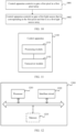
- the method includes: controlling to gate a first pixel in a first pixel array, where the first pixel is some or all pixels in the first pixel array; and controlling to gate a first light source that is corresponding to the first pixel and that is in a first light source array.
- a light source and a corresponding pixel may be gated in a row direction and/or a column direction in a self-defined manner without changing structures of the pixel array and the light source array, so that a quantity of equivalent lines in the row direction and/or the column direction of the detection system can be flexibly adjusted, and an angular resolution in the row direction or an angular resolution in the column direction of the detection system can be flexibly adjusted.
- the method further includes: obtaining a first electrical signal from a first pixel, and determining correlative information of a target based on the first electrical signal, where the first electrical signal is determined by the first pixel based on a received first echo signal, and the first echo signal is obtained by the target in a detection region by reflecting a first signal light emitted by the first light source.
- the method further includes: obtaining a first control signal that is used to control to gate the first pixel and/or the first light source; and sending the first control signal to the pixel array and/or the light source array, where the first control signal is generated based on at least a target angular resolution.
- the pixel in the pixel array is obtained through binning of p ⁇ q light-sensing units, where both p and q are integers greater than 1; and the method further includes: determining that a detection distance is less than a threshold, and extending point cloud information corresponding to the pixel to Q pieces, where Q is an integer greater than 1.
- an angular resolution of the detection system may be further improved by increasing an amount of point cloud information.
- the detection system is applied to a near-distance detection scenario, and a first angular resolution and a second angular resolution of the detection system may be further improved by increasing an amount of point cloud information.
- the method may further include: controlling to gate a ⁇ b light-sensing units in a central region of the pixel in the pixel array; and controlling to gate a light-sensing unit adjacent to at least one of the a ⁇ b light-sensing units, where the a ⁇ b light-sensing units are corresponding to one piece of first point cloud information, where a is less than p, and b is less than q, and the adjacent light-sensing unit outputs second point cloud information.
- the a ⁇ b light-sensing units are controlled to output one piece of first point cloud information, and the adjacent light-sensing unit outputs the second point cloud information, so that an amount of point cloud information can be increased.
- this application provides a control apparatus.
- the control apparatus is configured to implement the method according to any one of the second aspect or the possible implementations of the second aspect, and includes corresponding functional modules that are configured to implement steps in the foregoing method.
- the function may be implemented by hardware, or may be implemented by hardware executing corresponding software.
- the hardware or software includes one or more modules corresponding to the foregoing function.
- control apparatus is, for example, a chip, a chip system, a logic circuit, or the like.
- the control apparatus may include a transceiver module and a processing module.
- the processing module may be configured to support the control apparatus in performing a corresponding function in the method according to the second aspect.
- the transceiver module is configured to support interaction between the control apparatus and a detection system, another module in the detection system, or the like.
- the transceiver module may be an independent receiving module, an independent transmitting module, a transceiver module integrating a transceiver function, or the like.
- this application provides a control apparatus.
- the control apparatus is configured to implement the method according to any one of the third aspect or the possible implementations of the third aspect, and includes corresponding functional modules that are configured to implement steps in the foregoing method.
- the function may be implemented by hardware, or may be implemented by hardware executing corresponding software.
- the hardware or software includes one or more modules corresponding to the foregoing function.
- control apparatus is, for example, a chip, a chip system, a logic circuit, or the like.
- the control apparatus may include an interface circuit and a processor.
- the processor may be configured to support the control apparatus in performing a corresponding function in the method according to the second aspect.
- the interface circuit is configured to support interaction between the control apparatus and another structure in a detection system, the detection system, or the like.
- control apparatus may further include a memory.
- the memory may be coupled to the processor, and the memory stores program instructions and the like that are necessary for the control apparatus.
- this application provides a chip.
- the chip includes at least one processor and an interface circuit. Further, optionally, the chip may further include a memory.
- the processor is configured to execute a computer program or instructions stored in the memory, so that the chip performs the method according to any one of the second aspect or the possible implementations of the second aspect.
- this application provides a terminal device.
- the terminal device includes the detection system according to any one of the first aspect or the possible implementations of the first aspect.
- the terminal device may further include a processor, and the processor may be configured to control the detection system to detect a detection region.
- this application provides a computer-readable storage medium.
- the computer-readable storage medium stores a computer program or instructions.
- the control apparatus is enabled to perform the method according to any one of the second aspect or the possible implementations of the second aspect.
- this application provides a computer program product.
- the computer program product includes a computer program or instructions.
- the control apparatus is enabled to perform the method according to any one of the second aspect or the possible implementations of the second aspect.
- Binning is a reading manner. In this manner, signals (for example, photons) sensed by all light-sensing units in binned light-sensing units (or referred to as pixel cells) (cells) are added together and read in a manner of one pixel (Pixel). Binning can be classified into binning in a row direction and binning in a column direction. In the binning in a row direction, signals of adjacent rows are added and read in a manner of one pixel (refer to FIG. 1a below). In the binning in a column direction, signals of adjacent columns are added and read in a manner of one pixel.
- a detection system may implement row-only binning, or column-only binning, or row-and-column binning. It should be understood that, a binning manner may alternatively be another possible manner, for example, binning in a diagonal direction. This is not limited in this application.
- the quantity of lines of a detection system is a quantity of signal lights transmitted by the detection system at one time. Different signal lights may be used to detect different locations in a detection region. Refer to FIG. 1b .
- a quantity of lines of a detection system is 5. It should be understood that the quantity of lines of the detection system may be greater than 5, or may be less than 5. 5 is used only as an example in FIG. 1b . This is not limited in this application.
- the angular resolution may also be referred to as a scanning resolution, and refers to a capability of a detection system to differentiate a minimum distance between two adjacent objects.
- a smaller angular resolution indicates a larger quantity of light spots that are emitted to a detection region, that is, a larger quantity of points that can be detected and that are of a target in the detection region, and a higher detection definition.
- the angular resolution includes a first angular resolution and a second angular resolution, where the first angular resolution is an angular resolution in a row direction, and the second angular resolution is an angular resolution in a column direction.
- the first angular resolution ⁇ 1 may be represented by the following Formula 1
- the second angular resolution ⁇ 2 may be represented by the following Formula 2.
- a 1 represents a side length that is of a pixel and that is in a row direction of a pixel array
- a 2 represents a side length that is of a pixel and that is in a column direction of a pixel array
- f 1 represents an equivalent focal length that is of an optical receiving system and that is in a row direction
- f 2 represents an equivalent focal length that is of an optical receiving system and that is in a column direction.
- a 1 and a 2 may be the same or may be different, and f 1 and f 2 may be the same or may be different. This is not limited in this application.
- an angular resolution of a detection system is related to a size of a pixel in a pixel array at a receive end and a focal length of an optical receiving system. If the row direction is consistent with a horizontal direction, and the column direction is consistent with a vertical direction, an angular resolution in the horizontal direction may also be referred to as a first angular resolution, and an angular resolution in the vertical direction may also be referred to as a second angular resolution.
- the angular resolution of the detection system is the same as a size of a minimum field of view of a pixel.
- the first angular resolution of the detection system is the same as a minimum field of view in the row direction of the pixel
- the second angular resolution of the detection system is the same as a minimum field of view in the column direction of the pixel.
- the spatial resolution refers to a maximum quantity of pixel (Pixel) used for image-forming on a detection module.
- a spatial resolution is inversely correlated to a pixel size. That is, a smaller pixel size indicates a higher spatial resolution, and a larger pixel size indicates a lower spatial resolution.
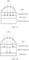
- Back side illumination back side illumination, BSI
- the BSI means that a light is incident from a back side into a pixel array.
- the light is focused on a color filter layer by a micro lens (micro lens) that includes an anti-reflective coating, and is divided into three primary color components by the color filter layer, and then directed to the pixel array.
- the back side is corresponding to a front end of line (front end of line, BEOL) process of a semiconductor manufacturing process.
- Front side illumination front side illumination, FSI
- the FSI means that a light is incident from a front side into a pixel array.
- a micro lens that includes an anti-reflective coating
- the front side is corresponding to a back end of line (back end of line, BEOL) process of a semiconductor manufacturing process.
- a row address may be a horizontal coordinate
- a column address may be a vertical coordinate.
- Data at a specified location in a memory may be read by using a row-column strobe signal, and a pixel corresponding to the read specified location is a gated pixel.
- a pixel in the pixel array may store a detected signal in a corresponding memory.
- a bias voltage may be used to enable a pixel to be in an active (active) state, to respond to an echo signal that is incident to a surface of the pixel.
- a row address may be a horizontal coordinate
- a column address may be a vertical coordinate.
- Gating a light source refers to lighting up (or turning on) a light source, and controlling the light source to transmit a signal light at a corresponding power.
- the point cloud information is a set of points in a three-dimensional space. These vectors are generally represented in a form of X, Y, and Z three-dimensional coordinates, and are usually used to represent correlative information of a target. For example, (X, Y, Z) may represent a geometric position, intensity, a depth (that is, a distance), a segmentation result, and the like of the target.
- the detection system may be a lidar.
- the lidar may be installed on a vehicle (for example, a self-driving vehicle, an intelligent vehicle, an electric vehicle, or a digital vehicle) as a vehicle-mounted lidar.
- the lidar may be deployed in any one or more directions of four directions: front, rear, left, and right of the vehicle, to capture information about an environment around the vehicle.
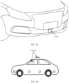
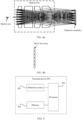
- FIG. 2a is an example in which the lidar is deployed in front of the vehicle.
- a region that can be sensed by the lidar may be referred to as a detection region of the lidar, and a corresponding field of view may be referred to as a full field of view.
- the lidar may obtain, in real time or periodically, a longitude and a latitude, a speed, and an orientation of the vehicle, or correlative information (for example, a distance of the target, a moving speed of the target, a posture of the target, or a grayscale image of the target) of a target (for example, another surrounding vehicle) in a specific range.
- the lidar or the vehicle may determine a location and/or path planning of the vehicle based on the correlative information. For example, a position of the vehicle is determined through the longitude and the latitude. Alternatively, a traveling direction and a destination of the vehicle in a future period of time are determined by using the speed and the orientation.
- a quantity of obstacles around the vehicle, density of the obstacles around the vehicle, and the like are determined by using the distance of the surrounding object.
- assisted driving, autonomous driving, or the like of the vehicle may be implemented based on a function of an advanced driving assistance system (advanced driving assistance system, ADAS).
- ADAS advanced driving assistance system
- a principle of detecting correlative information of a target by the lidar is as follows: The lidar transmits a signal light in a specific direction. If a target exists in a detection region of the lidar, the target may reflect the received signal light back to the lidar (a reflected signal light may be referred to as an echo signal), and then the lidar determines correlative information of the target based on the echo signal.
- the detection system may be a camera.
- the camera may alternatively be installed on a vehicle (for example, a self-driving vehicle, an intelligent vehicle, an electric vehicle, or a digital vehicle) as a vehicle-mounted camera. Refer to FIG. 2b .
- the camera can obtain measurement information such as a distance and a speed of an object in a detection region in real time or periodically to provide necessary information for operations such as lane correction, vehicle distance holding, and vehicle reversal.
- the vehicle-mounted camera can implement the following functions: (a) Object recognition and classification, such as lane line recognition, traffic light recognition, and traffic sign recognition; (b) Free space (Free Space) detection: For example, a safe boundary (drivable region) of a vehicle for driving may be divided, and a vehicle, an edge of a common road, an edge of a side stone, a boundary without a visible obstacle, an unknown boundary, and the like are divided; (c) Capability to detect laterally moving targets, such as a pedestrian and a vehicle passing through a crossroad; and (d) Localization and mapping, for example, localization and mapping based on a vision-based simultaneous localization and mapping (simultaneous localization and mapping, SLAM) technology; and the like.
- Object recognition and classification such as lane line recognition, traffic light recognition, and traffic sign recognition
- Free space (Free Space) detection For example, a safe boundary (drivable region) of a vehicle for driving may be divided, and a vehicle, an edge of a
- the lidar may alternatively be installed on an uncrewed aerial vehicle as an airborne radar.
- the lidar may alternatively be installed in a road side unit (road side unit, RSU), and may be used as a road side traffic lidar, to implement intelligent vehicle-road cooperative communication.
- the lidar may be installed on an automated guided transporter vehicle (automated guided vehicle, AGV).
- the AGV is a transporter vehicle equipped with an electromagnetic or optical automated navigation apparatus, or the like, capable of traveling along a specified navigation path, and having safety protection and various load-moving functions. This is not listed one by one herein. It should be understood that, the application scenarios described in this embodiment of this application are intended to describe the technical solutions in embodiments of this application more clearly, but constitute no limitation on the technical solutions provided in embodiments of this application. A person of ordinary skill in the art may learn that the technical solutions provided in embodiments of this application are also applicable to a similar technical problem as a new application scenario emerges.
- the application scenario may be applied to fields such as self driving, autonomous driving, assisted driving, intelligent driving, connected vehicles, security surveillance, remote interaction, mapping, or artificial intelligence.
- FIG. 3 is a schematic diagram of a structure of a detection system according to this application.
- the detection system 300 may include a pixel array 301 and a light source array 302.
- the pixel array 301 includes a first pixel array 3011
- the light source array 302 includes a first light source array 3021
- the first pixel array 3011 includes M ⁇ N pixels
- the first light source array 3021 includes M ⁇ N light sources corresponding to the M ⁇ N pixels, where M and N are integers greater than 1.
- the pixels in the first pixel array are arranged in a staggered manner in a row direction, and a staggering size of the pixels is less than a distance between centers of two adjacent pixels in the row direction; or the pixels in the first pixel array are arranged in a staggered manner in a column direction, and a staggering size of the pixels is less than a distance between centers of two adjacent pixels in the column direction; and an arrangement manner of the light sources in the first light source array is coupled to or matched with an arrangement manner of the pixels in the first pixel array.
- That light sources in the first light source array are arranged in a staggered manner in a row direction means that a light source in an i th row and a light source in a j th row are staggered at a specific size in the row direction, and the i th row and the j th row are adj acent to each other.
- that pixels in the first pixel array are arranged in a staggered manner in a column direction means that a pixel in an i th column and a pixel in a j th column are staggered at a specific size in the column direction (that is, two pixels in two adjacent columns are not aligned. Refer to FIG. 5c or FIG.
- the i th column and the j th column are two adjacent columns. That the light sources in the first light source array are arranged in a staggered manner in a column direction means that a light source in an i th column and a light source in a j th column are staggered at a specific size in the column direction, and the i th column and the j th column are two adjacent columns.
- the light sources in the first light source array are arranged in a staggered manner and the pixels in the first pixel array are arranged in a staggered manner.
- This is equivalent to increasing a quantity of equivalent lines of the detection system per unit area of the first pixel array (for details, refer to descriptions of four staggered arrangement manners provided below).
- the quantity of equivalent lines is increased, so that a quantity of light spots of an echo signal received per unit area of the first pixel array is increased, to help improve an angular resolution of the detection system.
- an angular resolution (which may be referred to as a first angular resolution) of the detection system in the row direction may be improved.
- an angular resolution (which may be referred to as a second angular resolution) of the detection system in the column direction may be improved.
- M ⁇ N light sources included in the first light source array are in a one-to-one correspondence with M ⁇ N pixels included in the first pixel array.
- the first light source array includes 2 ⁇ 2 light sources
- the first pixel array includes 2 ⁇ 2 pixels
- that the 2 ⁇ 2 light sources are in a one-to-one correspondence with the 2 ⁇ 2 pixels means that a light source 11 is corresponding to a pixel 11, a light source 12 is corresponding to a pixel 12, a light source 21 is corresponding to a pixel 21, and a light source 22 is corresponding to a pixel 22.
- the arrangement manner of light sources in the first light source array may be coupled to or matched with the arrangement manner of the pixels in the first pixel array by using an optical image-forming system. It may alternatively be understood that a signal light transmitted by a light source in the light source array may be imaged, by using the optical image-forming system, on a pixel corresponding to the light source. For the optical image-forming system, refer to the following related descriptions. Details are not described herein again.
- the pixel array may be a two-dimensional (two-dimensional, 2D) pixel array.
- a pixel in the pixel array may be obtained through binning (binning) of at least one light-sensing unit (cell) (or referred to as a pixel element).
- the light-sensing unit may be, for example, a single photon detector, and the single photon detector includes but is not limited to an SPAD or a digital silicon photomultiplier (silicon photomultiplier, SiPM).
- the single photon detector may be formed by using an FSI process or a BSI process. Usually, a BSI process can be used to achieve a small SPAD size, a high PDE, and high energy efficiency.
- FIG. 4 is a schematic diagram of a structure of a pixel according to this application.
- the pixel is obtained by binning of 4 ⁇ 4 light-sensing units.
- a binning manner of light-sensing units is 4 ⁇ 4.
- one pixel includes 4 ⁇ 4 light-sensing units.
- the binning manner of light-sensing units shown in FIG. 4 is merely an example. In this application, binning of light-sensing units may be performed only in the row direction, or binning of light-sensing units may be performed only in the column direction.
- a shape of a pixel may be a square, or may be a rectangle (as shown in FIG. 4 ), or may be another possible regular shape (for example, a hexagon, a circle, or an ellipse).
- a specific shape of a pixel is related to a light-sensing unit forming the pixel and a binning manner of light-sensing units. If the pixel is a rectangle, a length side of the pixel may be in the row direction, or may be in the column direction.
- a light-sensing unit is usually a symmetric regular pattern, for example, a square (refer to FIG. 4 ). Certainly, a rectangle may alternatively be used. This is not limited in this application.
- the first pixel array may be all of a pixel array.
- the pixel array includes the M ⁇ N pixels. Based on this, the first pixel array in this application may be replaced with a pixel array.
- the first pixel array may be some pixels of the pixel array. That is, in addition to the first pixel array formed by the M ⁇ N pixels, the pixel array may further include another pixels. Based on this, the pixel array may form a regular graph (for example, a rectangle or a square), or may form an irregular graph. This is not limited in this application.
- the pixels in the first pixel array may be arranged in a staggered arrangement manner.
- the following shows an example of a possible staggered arrangement manner of the pixels in the first pixel array.
- the pixels in the first pixel array are rectangles, and a staggering size is based on a center of an image region.
- the image region refers to a region that is in a pixel and that is used to receive an echo signal from a detection region (refer to the following elliptic region shown in FIG. 5a to FIG. 5d ). It may alternatively be understood that an image corresponding to the echo signal is formed in the image region of the pixel. In other words, the image region is an image-forming location of the echo signal.
- Manner 1 Arranged in a staggered manner at an equal space in a row direction.
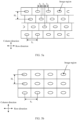
- FIG. 5a is a schematic diagram of a structure in which the pixels of the first pixel array are arranged in a staggered manner in a row direction according to this application.
- the pixels in the first pixel array are arranged in a staggered manner at an equal space in the row direction and arranged in a staggered manner in a periodicity of N rows, where N is an integer greater than 1.
- the staggering size ⁇ 1 between any two adjacent pixels in the row direction is less than a distance S 1 between centers of the two adjacent pixels.
- an equivalent focal length of the receiving optical system in the row direction is f 1 .
- an equivalent side length of the pixels in the first pixel array in the row direction is a 1
- a first angular resolution ⁇ 1 a1/f1.
- an equivalent side length of the pixels in the first pixel array in the row direction is a 1 /3
- a first angular resolution ⁇ 1 ' a 1 /3f 1 .
- the staggered arrangement manner of the first pixel array shown in FIG. 5a may increase the angular resolution in the row direction by three times. It should be understood that, based on the arrangement manner of the first pixel array in FIG. 5b , in a range of S 1 in the row direction, a minimum field of view corresponding to pixels is a field of view corresponding to a length S 1 . Based on the arrangement manner of the first pixel array in FIG. 5a , a minimum field of view corresponding to pixels is a field of view corresponding to a length S 1 /3.
- an angular resolution based on the staggered arrangement manner of the pixels in the first pixel array shown in FIG. 5a is the same as an angular resolution based on the arrangement manner of the pixels in the first pixel array shown in FIG. 5b .
- Manner 2 Arranged in a staggered manner at an equal space in a column direction.
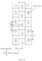
- FIG. 5c is a schematic diagram of a structure in which the pixels of the first pixel array are arranged in a staggered manner in a column direction according to this application.
- the pixels in the first pixel array are arranged in a staggered manner at an equal space in the column direction and arranged in a staggered manner in a periodicity of M columns.
- a focal length of the receiving optical system in the column direction is f 2 .
- an equivalent side length of the pixels in the first pixel array in the column direction is b 1
- a second angular resolution ⁇ 2 b 1 /f 2 .
- a side length of the pixels in the first pixel array in the column direction is b 1 /3
- a second angular resolution ⁇ 2 ' b 1 /3/f 2 .
- the staggered arrangement manner of the first pixel array shown in FIG. 5c may increase the angular resolution in the column direction by three times. It should be understood that, based on the arrangement manner of the first pixel array in FIG. 5d , in a range of H 2 in the row direction, a minimum field of view corresponding to pixels is a field of view corresponding to a length H 2 . Based on the arrangement manner of the first pixel array in FIG. 5c , a minimum field of view corresponding to pixels is a field of view corresponding to a length H 2 /3.
- an angular resolution based on the staggered arrangement manner of the pixels in the first pixel array shown in FIG. 5c is the same as an angular resolution based on the arrangement manner of the pixels in the first pixel array shown in FIG. 5d .
- the staggering size ⁇ 1 in Manner 1 may be the same as or different from the staggering size ⁇ 2 in Manner 2. This is not limited in this application.
- Manner 3 Arranged in a staggered manner at non-equal spaces in the row direction.
- FIG. 5e is a schematic diagram of another structure in which the pixels of the first pixel array are arranged in a staggered manner in a row direction according to this application.
- a staggering size between two adjacent pixels in the row direction is ⁇ 3 or ⁇ 4 .
- ⁇ 3 is less than ⁇ 4 .
- the staggering size ⁇ 3 between any two adjacent pixels in the row direction is less than a distance S 1 between centers of the two adjacent pixels, and the staggering size ⁇ 4 between any two adjacent pixels in the row direction is also less than the distance S 1 between the centers of the two adjacent pixels.
- the first pixel array has at least two different first angular resolutions in the row direction. For example, if there are two different staggering sizes in the row direction, there are two different first angular resolutions in the row direction. For another example, if there are three different staggering sizes in the row direction, there are three different first angular resolutions in the row direction.
- staggering sizes in the staggered arrangement at non-equal spaces in the row direction may be different from each other (as shown in FIG. 5e ), or some of the staggering sizes may be the same and some of the staggering sizes are different. This is not limited in this application.
- an equivalent focal length of the receiving optical system in the row direction is f 1 .
- a first angular resolution ⁇ 1 a 1 /f 1 .
- the staggered arrangement manner of the first pixel array shown in FIG. 5e can improve an angular resolution in the row direction. It should be understood that, based on the arrangement manner of the first pixel array shown in FIG. 5e , in the row direction, a minimum field of view corresponding to pixels is a field of view corresponding to ⁇ 3 .
- an overall angular resolution of the first pixel array may be obtained based on the two first angular resolutions. For example, weighted averaging may be performed on the two first angular resolutions. For another example, a resolution of a central region of a point cloud may be used as the overall angular resolution of the first pixel array.
- an angular resolution based on the staggered arrangement manner of the pixels in the first pixel array shown in FIG. 5e is the same as an angular resolution based on the arrangement manner of the pixels in the first pixel array shown in FIG. 5b .
- Manner 4 Arranged in a staggered manner at non-equal spaces in the column direction.
- FIG. 5f is a schematic diagram of another structure in which the pixels of the first pixel array are arranged in a staggered manner in a column direction according to this application.
- a staggering size between two adjacent pixels in the column direction is ⁇ s or ⁇ 6 .
- a staggering size ⁇ s of any two adjacent pixels in the column direction is less than a distance H 2 between centers of the two adjacent pixels, and a staggering size ⁇ 6 of any two adjacent pixels in the column direction is less than the distance H 2 between centers of two adjacent pixels.
- the first pixel array has at least two different second angular resolutions in the column direction. For example, if there are two different staggering sizes in the column direction, there are two different second angular resolutions in the column direction. For another example, if there are three different staggering sizes in the column direction, there are three different second angular resolutions in the column direction.
- staggering sizes in the staggered arrangement at non-equal spaces in the column direction may be different from each other (as shown in FIG. 5f ), or some of the staggering sizes may be the same and some of the staggering sizes are different. This is not limited in this application.
- an equivalent focal length in the row direction of the receiving optical system is f 1 .
- the second angular resolution ⁇ 2 b 1 /f 2 .
- the two second angular resolutions are less than the second angular resolution ⁇ 2 shown in FIG. 5d .
- the staggered arrangement manner of the first pixel array shown in FIG. 5f can improve an angular resolution of the detection system in a column direction. It should be understood that, based on the arrangement manner of the first pixel array in FIG. 5d , in a range of H 2 in the row direction, a minimum field of view corresponding to pixels is a field of view corresponding to a length H 2 . Based on the arrangement manner of the first pixel array in FIG. 5f , a minimum field of view corresponding to pixels is a field of view corresponding to a length ⁇ s.
- an angular resolution based on the staggered arrangement manner of the pixels in the first pixel array shown in FIG. 5f is the same as an angular resolution based on the arrangement manner of the pixels in the first pixel array shown in FIG. 5d .
- a staggering size of the pixels in the first pixel array depends on an application scenario of the detection system. For example, in a scenario in which a small angular resolution is required, a staggering size of the pixels is small. For another example, in a scenario in which a large angular resolution is required, a staggering size of the pixels is large. It should be understood that a smaller staggering size indicates a smaller angular resolution of the detection system and a larger improved spatial resolution.
- a periodicity (M or N) of the first pixel array for a staggered arrangement may be designed based on an application requirement of the detection system.
- pixels in the foregoing four manners are all rectangles. If the pixel is a circle, determined side lengths of the first angular resolution and the second angular resolution may be replaced by radii. If the pixel is an ellipse, a determined side length of the first angular resolution may be replaced with a length of a major axis (or a length of a minor axis) of the ellipse, and correspondingly, a determined side length of the second angular resolution may be replaced with a length of a minor axis (or a length of a major axis) of the ellipse.
- a determined side length of the first angular resolution may be replaced with a maximum side length in a row direction
- a determined side length of the second angular resolution may be replaced with a maximum side length in a column direction.
- the pixels in the first pixel array may alternatively be arranged in a staggered manner in the row direction based on a combination of the foregoing Manner 1 and Manner 2, that is, some of the pixels are arranged in a staggered manner at an equal space, and some of the pixels are arranged at non-equal spaces.
- Staggering sizes in the row direction are ⁇ 7 , ⁇ s, and ⁇ 7 .
- Both the two types of first angular resolutions are less than the first angular resolution ⁇ 1 based on FIG. 5b
- an overall angular resolution of the first pixel array may be obtained based on the two first angular resolutions. For example, weighted averaging may be performed on the two first angular resolutions, where a weight of ⁇ 1 ⁇ may be greater than a weight of ⁇ 1 ⁇ ′′′.
- the pixels in the first pixel array may alternatively be arranged in a staggered manner in a column direction based on a combination of the foregoing Manner 3 and Manner 4, that is, some of the pixels are arranged in a staggered manner at an equal space, and some of the pixels are arranged in a staggered manner at non-equal spaces.
- Staggering sizes in the column direction are ⁇ 9 , ⁇ 0 , and ⁇ 9 .
- Both the two types of second angular resolutions are less than the second angular resolution ⁇ 2 based on FIG. 5d .
- an overall angular resolution of the first pixel array may be obtained based on the two second angular resolutions. For example, weighted averaging may be performed on the two second angular resolutions, where a weight of ⁇ 2 ⁇ may be greater than a weight of ⁇ 2 ′′′ ⁇ .
- the first pixel array may include only one region, that is, the entire first pixel array is corresponding to one type of first angular resolution and one type of second angular resolution.
- the entire first pixel array uses a same staggered arrangement manner, a same staggering size, and a same binning manner of the light-sensing units.
- the first pixel array may include at least two different regions, and each region may correspond to at least one first angular resolution or at least one second angular resolution. It may alternatively be understood that the full field of view of the detection system may be corresponding to at least two different first angular resolutions or at least two different second angular resolutions. It should be understood that, when all pixels in the first pixel array are gated, a corresponding field of view is the full field of view of the detection system.
- the following example shows a possible case in which the first pixel array includes at least two different regions.
- Case 1 The first pixel array is divided into a plurality of first regions based on different staggered arrangement manners.
- the first pixel array includes m first regions, there are at least two first regions in the m first regions, and pixels in the at least two first regions each are arranged in a different staggered manner, where m is an integer greater than 1.
- the first pixel array may use a combination of at least two of the foregoing four staggered arrangement manners.
- one staggered arrangement manner is corresponding to one first region.
- the first region of the first pixel array is divided based on a staggered arrangement manner. Specific combinations may be determined based on an application scenario of the detection system.
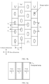
- FIG. 6a is a schematic diagram of a structure of a first pixel array according to this application.
- the first pixel array includes three first regions (that is, a first region 1, a first region 2, and a first region 3), and each first region is corresponding to one pixel staggered arrangement manner.
- pixel arrangement manners corresponding to the three first regions are different from each other.
- the first region 1 may be arranged in a staggered manner in the foregoing Manner 1
- the first region 2 may be arranged in a staggered manner in the foregoing Manner 2
- the first region 3 may be arranged in a staggered manner in the foregoing Manner 3.
- a field of view of the first region 1 is corresponding to a first angular resolution 1 and a second angular resolution 1
- a field of view of the first region 2 is corresponding to a first angular resolution 2 and a second angular resolution 2
- a field of view of the first region 3 is corresponding to a first angular resolution 3 and a second angular resolution 3.
- the first region 1 may be arranged in a staggered manner in the foregoing Manner 1
- the first region 2 may be arranged in a staggered manner in the foregoing Manner 2
- the first region 3 may be arranged in a staggered manner in the foregoing Manner 4.
- a field of view of the first region 1 is corresponding to a first angular resolution 1' and a second angular resolution 1'
- a field of view of the first region 2 is corresponding to a first angular resolution 2' and a second angular resolution 2'
- a field of view of the first region 3 is corresponding to a first angular resolution 3' and a second angular resolution 3', and details are not repeated herein.
- first angular resolutions and/or second angular resolutions may be corresponding to different field angles of view without changing a binning manner of light-sensing units.
- a shaded region in FIG. 6a may be considered as an ineffective pixel for the first angular resolution and the second angular resolution, that is, a light-sensing unit of the shaded region is not used by default. Further, these light-sensing units in the shaded regions may perform some other functions, for example, assist in implementing background ambient light intensity detection and data collection.
- Case 2 The first pixel array is divided into a plurality of regions based on different binning manners of the light-sensing units.
- the first pixel array includes n second regions, there are at least two second regions in the n second regions, pixels in the at least two second regions each are obtained through binning of a different quantity of light-sensing units, where n is an integer greater than 1.
- binning manners of light-sensing units in different second regions of the first pixel array are different. Based on this, the different second regions of the first pixel array may use a same staggered arrangement manner, and staggering sizes in the different second regions are also the same. It should be noted that, lengths-width ratios of the pixels in the first pixel array may be the same or may be different. When the length-width ratios of the pixels in the first pixel array are different, a rotationally symmetric optical image-forming system with an effective degree of freedom may be used to implement angular resolution adjustment.
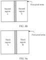
- FIG. 6b is a schematic diagram of another structure of a first pixel array according to this application.
- the first pixel array may be divided into two second regions (that is, a second region a and a second region b).
- the second region a and the second region b both use the staggered arrangement manner provided in the foregoing Manner 1.
- a staggering size in the second region a is the same as a staggering size in the second region b, and a binning manner of light-sensing units in the second region a is different from a binning manner of light-sensing units in the second region b.
- a first angular resolution corresponding to a field of view of the second region a is different from a first angular resolution corresponding to a field of view of the second region b
- a second angular resolution corresponding to the field of view of the second region a is different from a second angular resolution corresponding to the field of view of the second region b.
- a center field of view in the full field of view of a detection system usually requires a higher angular resolution, and an edge field of view in the full field of view may use a slightly lower angular resolution. Based on this, binning of fewer light-sensing units may be set in a central region of the first pixel array, and binning of more light-sensing units may be set in an edge region.
- the m first regions in Case 1 may overlap the n second regions in Case 2 respectively.
- the m first regions include a first region 1, a first region 2, and a first region 3,
- the n second regions include a second region A, a second region B, and a second region C, the first region 1 overlaps the second region A, the first region 2 overlaps the second region B, and the first region 3 overlaps the second region C.
- Case 3 The first pixel array is divided into a plurality of third regions based on different staggering sizes.
- the first pixel array includes h third regions, there are at least two third regions in the h third regions, pixels in the at least two third regions each have a different staggering size, where h is an integer greater than 1.
- different third regions in the first pixel array have different staggering sizes.
- different third regions of the first pixel array may use a same staggered arrangement manner, and the different third regions have different staggering sizes.
- FIG. 6c is a schematic diagram of still another structure of a first pixel array according to this application.
- the first pixel array is divided into two third regions (that is, a third region A and a third region B), a staggering size of the third region A is less than a staggering size of the third region B, and both the third region A and the third region B use the staggered arrangement manner provided in the foregoing Manner 1.
- a first angular resolution corresponding to a field of view of the third region A is less than a first angular resolution corresponding to a field of view of the third region B
- a second angular resolution corresponding to the field of view of the third region A is equal to a second angular resolution corresponding to the field of view of the third region B.
- a center field of view in the full field of view of a detection system usually requires a higher angular resolution, and an edge field of view in the full field of view may use a slightly lower angular resolution.
- a small staggering size may be set for a central region of the first pixel array, and a large staggering size may be set for an edge region. It should be understood that the central region of the first pixel array is corresponding to the central field of view in the full field of view, and the edge region of the first pixel array is corresponding to the edge field of view in the full field of view.
- the m first regions in Case 1 may overlap the h third regions in Case 3 respectively.
- the m first regions include a first region 1, a first region 2, and a first region 3, and the h third regions include a third region A, a third region B, and a third region C.
- the first region 1 overlaps the third region A
- the first region 2 overlaps the third region B
- the first region 3 overlaps the third region C.
- the n second regions in Case 2 may overlap the h third regions in Case 3 respectively.
- the n second regions include a second region A, a second region B, and a second region C
- the h third regions include a third region A, a third region B, and a third region C
- the second region A overlaps the third region A
- the second region B overlaps the third region B
- the second region C overlaps the third region C.
- the implementation that the full field of view is corresponding to different first angular resolutions and/or second angular resolutions may also be a combination of the foregoing cases.
- the foregoing Case 1 and Case 3 are combined.
- the region 1 may be further divided into a region 11 and a region 12 based on staggering sizes is used.
- a field of view of the region 11 is corresponding to a first angular resolution ⁇ 111 and a second angular resolution ⁇ 112
- a field of view of the region 12 is corresponding to a first angular resolution ⁇ 121 and a second angular resolution ⁇ 122 .
- the region 2 and the region 3 may be further divided into regions based on staggering sizes, and details are not repeated herein.
- the region A may be further divided into a region A1 and a region A2 based on staggered arrangement manners.
- a field of view of the region A1 is corresponding to a first angular resolution ⁇ A11 and a second angular resolution ⁇ A12
- a field of view of the region A2 is corresponding to a first angular resolution ⁇ A21 and a second angular resolution ⁇ A22 .
- the region B may be further divided into regions based on staggering sizes, and details are not repeated herein.
- Case 1 and Case 2 are combined.
- the region 1 may be further divided into a region 1a and a region 1b based on a binning manner of light-sensing units is used.
- a field of view of the region 1a is corresponding to a first angular resolution ⁇ 1a1 and a second angular resolution ⁇ 1a2
- a field of view of the region 12 is corresponding to a first angular resolution ⁇ 1b1 and a second angular resolution ⁇ 1b2 .
- the region 2 and the region 3 may also be further divided into regions based on binning manners of light-sensing units, and details are not repeated herein.
- the region a may be further divided into a region a1 and a region a2 based on staggered arrangement manners.
- a field angle of view of the region a1 is corresponding to a first angular resolution ⁇ a11 and a second angular resolution ⁇ a12
- a field angle of view of the region a2 is corresponding to a first angular resolution ⁇ a21 and a second angular resolution ⁇ a22 .
- the region b may also be further divided into regions based on staggered arrangement manners, and details are not repeated herein.
- the region A may be further divided into a region Aa and a region Ab based on binning manners of light-sensing units.
- a field of view of the region Aa is corresponding to a first angular resolution ⁇ Aa1 and a second angular resolution ⁇ Aa2
- a field of view of the region Ab is corresponding to a first angular resolution ⁇ Ab1 and a second angular resolution ⁇ Ab2 .
- the region B may also be further divided into regions based on binning manners of light-sensing units, and details are not repeated herein.
- the region a may be further divided into a region aA and a region aB based on staggering sizes.
- a field angle of view of the region aA is corresponding to a first angular resolution ⁇ aA1 and a second angular resolution ⁇ aA2
- a field angle of view of the region aB is corresponding to a first angular resolution ⁇ aB1 and a second angular resolution ⁇ aB2 .
- the region b may also be further divided into regions based on staggering sizes, and details are not repeated herein.
- the region 1 may be further divided into a region 11 and a region 12 based on staggering sizes
- the region 11 may be further divided into a region 111 and a region 112 based on binning manners of light-sensing units.
- a field of view of the region 111 is corresponding to a first angular resolution ⁇ 1111 and a second angular resolution ⁇ 1112
- a field of view of the region 112 is corresponding to a first angular resolution ⁇ 1121 and a second angular resolution ⁇ 1122 .
- region 2 and the region 3 may also be further divided into regions based on staggering sizes, and the region obtained after further division is further divided into regions based on binning manners of light-sensing units, and details are not repeated herein.
- the region A may be further divided into a region A11 and a region A21 based on staggered arrangement manners.
- region A11 may be divided into a region A11a and a region A21b based on binning manners of light-sensing units.
- a field of view of the region A11a is corresponding to a first angular resolution ⁇ A11a1 and a second angular resolution ⁇ A11a2
- a field of view of the region A21b is corresponding to a first angular resolution ⁇ 21b1 and a second angular resolution ⁇ 21b2 . It should be understood that other possible combinations may be used, and details are not repeated herein.
- the first pixel array may be a same chip.
- different regions of a same chip may correspond to a different first angular resolution and/or a second angular resolution.
- the first pixel array may perform optical-to-electrical conversion on a received echo signal, to obtain correlative information used to determine a target in a detection region, for example, distance information of the target, an orientation of the target, a speed of the target, and/or grayscale information of the target.
- the light source array may be a 2D addressable light source array.
- the addressable light source array refers to a light source that can be independently gated (or referred to as light-on, turn-on, or power-on) in the light source array, and the gated light source may be used to transmit a signal light.
- the light source array includes a first light source array.
- the first light source array is the entire light source array, that is, the light source array includes M ⁇ N light sources corresponding to the M ⁇ N pixels. Based on this, the first light source array in this application may be replaced with a light source array.
- the first light source array may be some light sources in the light source array.
- the light source array may further include another light source. Based on this, the light source array may form a regular pattern, or may form an irregular pattern. This is not limited in this application.
- the light source in the light source array may be a vertical cavity surface emitting laser (vertical cavity surface emitting laser, VCSEL), an edge emitting laser (edge emitting laser, EEL), an all-solid-state semiconductor laser (diode pumped solid state laser, DPSS), or an optical fiber laser.
- VCSEL vertical cavity surface emitting laser
- EEL edge emitting laser
- DPSS all-solid-state semiconductor laser
- optical fiber laser optical fiber laser
- the Vcsel is used as an example.
- the Vcsel may include an optical area (optical area, OA).
- the optical area is an area used by the Vcsel to transmit a signal light, and another area of the Vcsel does not emit a light.
- the optical area may be located in a central region of the Vcsel, or may be located in an edge region of the Vcsel, or may be located in another region of the Vcsel. This is not limited in this application.
- the optical area of the Vcsel is corresponding to an image region of a pixel corresponding to the Vcsel.
- a location of an image region of a pixel covered by an image of an echo signal that is obtained by a target in a detection region reflecting a signal light transmitted by the optical area of the Vcsel may be changed by adjusting a location of the optical area of the Vcsel (for example, adjusting central coordinates of the optical area).
- a location of the optical area of the Vcsel for example, adjusting central coordinates of the optical area.
- the light source array includes k regions, there are at least two regions in the k regions, and an optical area of a light source in the at least two regions each have a different location relative to the light source, where k is an integer greater than 1. Spatial arrangement manners (that is, locations relative to light sources) of optical areas of Vcsels in some regions in the first light source array are changed. To be specific, in different regions of the first light source array, optical areas of the light sources are disposed at different locations relative to the light sources. This helps implement a different first angular resolution or a different second angular resolution corresponding to a different field angle of view without changing a structure of the first pixel array.
- the first pixel array and the first light source array are closely related in terms of an arrangement manner and a specification design. Further, optionally, an arrangement manner of the light sources in the first light source array is matched with an arrangement manner of the pixels in the first pixel array. If the arrangement manner of the pixels in the first pixel array is the foregoing Manner 1, the arrangement manner of the light sources in the first light source array may alternatively be the arrangement manner shown in FIG. 5a . If the arrangement manner of the pixels in the first pixel array is the foregoing Manner 2, the arrangement manner of the light sources in the first light source array may alternatively be the arrangement manner shown in FIG. 5c .
- the arrangement manner of the light sources in the first light source array may alternatively be the arrangement manner shown in FIG. 5e .
- the arrangement manner of the pixels in the first pixel array is the foregoing Manner 4
- the arrangement manner of the light sources in the first light source array may alternatively be the arrangement manner shown in FIG. 5f .
- the arrangement manner of the pixels in the first pixel array is FIG. 5g
- the arrangement manner of the light sources in the first light source array may alternatively be the arrangement manner shown in FIG. 5g .
- the arrangement manner of the pixels in the first pixel array is FIG. 5h
- the arrangement manner of the light sources in the first light source array may alternatively be the arrangement manner shown in FIG. 5h .
- For a specific arrangement manner of the light sources in the first light source array refer to a corresponding arrangement manner of the pixels in the first pixel array. An image region in a pixel may be replaced with an optical area. Details are not described herein again.
- first light source array and the first pixel array use a same staggered arrangement manner, but a staggering size of the light sources may be different from a staggering size of the pixels.
- one light source is corresponding to one pixel, and one pixel may be obtained by binning of m ⁇ n light-sensing units.
- the following shows a correspondence between a light source and a light-sensing unit as an example.
- FIG. 7 shows a correspondence between a light source and a light-sensing unit according to this application.
- the first pixel array includes 2 ⁇ 2 pixels (that is, a pixel 11, a pixel 12, a pixel 21, and a pixel 22), the first light source array includes 2 ⁇ 2 light sources (that is, a light source 11, a light source 12, a light source 21, and a light source 22), and each pixel includes 4 ⁇ 4 SPADs.
- the pixel 11 is corresponding to the light source 11, the pixel 12 is corresponding to the light source 12, the pixel 21 is corresponding to the light source 21, the pixel 22 is corresponding to the light source 22, and an optical area of each light source is corresponding to an image region of a corresponding pixel.
- the pixel array obtained when pixels are arranged in a staggered manner may be referred to as an abnormal-shaped structure
- the light source array obtained when light sources are arranged in a staggered manner may also be referred to as an abnormal-shaped structure.
- the detection system may further include an optical image-forming system
- the optical image-forming system may include a transmitting optical system and a receiving optical system.
- the transmitting optical system and the receiving optical system may be the same, or the transmitting optical system and the receiving optical system may be different. This is not limited in this application. Any optical image-forming system that can image, on a corresponding pixel, a signal light emitted by a light source in a light source array falls within the protection scope of this application. The following uses an example in which the transmitting optical system is the same as the receiving optical system for description.
- a signal light transmitted by a light source in the light source array may be shaped and/or collimated by the transmitting optical system and then emitted to a detection region, and an echo signal is obtained by reflecting the signal light by a target in the detection region.
- the echo signal is then shaped and/or collimated by the receiving optical system and then received by a corresponding pixel in the pixel array.
- a signal light transmitted by an optical area of the light source 11 is transmitted by the transmitting optical system and then is emitted to a detection region, and an echo signal is obtained by reflecting the signal light by a target in the detection region.
- the echo signal may be imaged in an image region of the corresponding pixel 11.
- a signal light transmitted by an optical area of the light source 12 is transmitted by the transmitting optical system and then is emitted to a detection region, and an echo signal is obtained by reflecting the signal light by a target in the detection region.
- the echo signal may be imaged in an image region of the corresponding pixel 12.
- a signal light transmitted by an optical area of the light source 21 is transmitted by the transmitting optical system and then is emitted to a detection region, and an echo signal is obtained by reflecting the signal light by a target in the detection region.
- the echo signal may be imaged in an image region of the corresponding pixel 21.
- a signal light transmitted by an optical area of the light source 22 is transmitted by the transmitting optical system and then is emitted to a detection region, and an echo signal is obtained by reflecting the signal light by a target in the detection region.
- the echo signal may be imaged in an image region of the corresponding pixel 22.
- one-to-one alignment between a transmitting field of view of the light source in the light source array and a receiving field of view of the pixel in the pixel array may be implemented based on an optical principle of focal plane image-forming. That is, a transmitting field of view of each light source in the light source array and a receiving field of view of each pixel in the pixel array are in a one-to-one correspondence in space. In other words, one pixel is corresponding to one receiving field of view, one light source is corresponding to one transmitting field of view, and the receiving field of view and the transmitting field of view are in one-to-one alignment in space.
- each light source in the light source array is on an object side of the optical image-forming system, and a photosensitive surface of each pixel in the pixel array is located on an image side of the optical image-forming system.
- the light source in the light source array is on an object side focal plane of the transmitting optical system, and the photosensitive surface of the pixel in the pixel array is on an image side focal plane of the receiving optical system.
- the signal light emitted by the light source in the light source array is transmitted to the detection region through the transmitting optical system, and the echo signal obtained by the target reflecting the signal light in the detection region can be imaged on the image side focal plane through the receiving optical system.
- the transmitting optical system and the receiving optical system usually use a same optical lens.
- the transmitting optical system and the receiving optical system are simple and can be modularized, so that the detection system can be small in size, highly integrated, and the like.
- FIG. 8a is a schematic diagram of a structure of an optical lens according to this application.
- the optical lens includes at least one lens element.
- the lens element may be, for example, a lens.
- An optical axis of the optical lens refers to a straight line that passes through a spherical sphere center of each lens shown in FIG. 8a .
- the optical lens may be rotationally symmetric about the optical axis.
- the lens element in the optical lens may be a single spherical lens, or may be a combination of a plurality of spherical lenses (for example, such as a combination of concave lenses, a combination of convex lenses, or a combination of a convex lens and a concave lens).
- a combination of a plurality of spherical lenses helps improve image-forming quality of the detection system and reduce aberration of the optical image-forming system.
- the convex lens and the concave lens have a plurality of different types.
- the convex lens includes a biconvex lens, a flat convex lens, and a concave convex lens
- the concave lens includes a biconcave lens, a flat concave lens, and a concave convex lens. This helps improve a multiplex rate of an optical component of the detection system, and facilitates installation and adjustment of the detection system.
- a horizontal equivalent focal length and a vertical equivalent focal length of the optical lens that is rotationally symmetric about the optical axis are the same.
- the lens element in the optical lens may alternatively be a single aspheric lens or a combination of a plurality of aspheric lenses. This is not limited in this application.
- a material of the lens element in the optical lens may be an optical material such as glass, resin, or crystal.
- the material of the lens element is resin, it helps to reduce a weight of the detection system.
- the material of the lens element is glass, this helps further improve image-forming quality of the detection system.
- the optical lens includes at least one lens element made of a glass material.
- FIG. 8b is a schematic diagram of a structure of another optical lens according to this application.
- the optical lens is a micro-lens array (micro lens array, MLA).
- MLA micro lens array
- the micro lens array may collimate and/or shape a signal light from the light source array, and transmit the collimated and/or shaped signal light to a detection region.
- the micro lens array may implement a signal light collimation degree of 0.05° to 0.1°.
- the foregoing provided structure of the optical lens may be used as the transmitting optical system, or may be used as the receiving optical system, or both the transmitting optical system and the receiving optical system use the foregoing structure of the optical lens.
- the transmitting optical system and the receiving optical system may alternatively be other possible structures, for example, micro optical systems that are stuck on a surface of the light source array and a surface of the pixel array. This is not limited in this application.
- a focal length of the receiving optical system may change with a field angle of view of the detection system, a different field of view may be corresponding to a different first angular resolution and/or a second angular resolution by changing the focal length of the receiving optical system.
- a length-width ratio of a light source in the first light source array is the same as a length-width ratio of a corresponding pixel in the first pixel array. Based on this, focal lengths of the transmitting optical system and the receiving optical system may be the same. In another possible implementation, a length-width ratio of a light source in the light source array is equal to a 1 : a 2 . Based on this, a focal length ratio of the transmitting optical system to the receiving optical system is equal to a 2 : a 1 . It may alternatively be understood that the first light source array and the first pixel array are mapped in a one-to-one manner in space by using the receiving optical system and the transmitting optical system, which may be referred to as being coupled or matched.
- the detection system may further include a control module.
- the control module may be a central processing unit (central processing unit, CPU), or may be another general-purpose processor (for example, a microprocessor, or may be any conventional processor), a field programmable gate array (field programmable gate array, FPGA), a signal data processing (digital signal processing, DSP) circuit, an application-specific integrated circuit (application-specific integrated circuit, ASIC), a transistor logic device, or another programmable logic device, or any combination thereof.
- CPU central processing unit
- FPGA field programmable gate array
- DSP digital signal processing
- ASIC application-specific integrated circuit
- ASIC application-specific integrated circuit
- transistor logic device or another programmable logic device, or any combination thereof.
- control module when the detection system is applied to a vehicle, the control module may be used to plan a driving path based on determined correlative information of the detection region, for example, avoid an obstacle on a road to be traveled on.
- the detection system in any one of the foregoing embodiments may be a lidar, for example, a pure solid-state lidar.
- FIG. 9 is a schematic diagram of a structure of a terminal device according to an embodiment of this application.
- the terminal device 900 may include the detection system 901 in any one of the foregoing embodiments. Further, optionally, the terminal device may further include a processor 902.
- the processor 902 is configured to invoke a program or instructions to control the detection system 901 to detect a detection region. Further, the processor 902 may further receive an electrical signal that is obtained through optical-to-electrical conversion of an echo signal and that is from the detection system 901, and determine correlative information of a target based on the electrical signal.
- the terminal device may further include a memory 903, and the memory 903 is configured to store a program or instructions.
- the terminal device may also include other components, such as a wireless communication apparatus.
- the processor 902 may include one or more processing units.
- the processor 902 may include an application processor (application processor, AP), a graphics processing unit (graphics processing unit, GPU), an image signal processor (image signal processor, ISP), a controller, and a digital signal processor (digital signal processor, DSP).
- application processor application processor
- GPU graphics processing unit
- ISP image signal processor
- controller controller
- DSP digital signal processor
- Different processing units may be independent components, or may be integrated into one or more processors.
- the memory 903 includes but is not limited to a random access memory (random access memory, RAM), a flash memory, a read-only memory (read-only memory, ROM), a programmable read-only memory (programmable ROM, PROM), an erasable programmable read-only memory (erasable PROM, EPROM), an electrically erasable programmable read-only memory (electrically EPROM, EEPROM), a register, a hard disk, a removable hard disk, a CD-ROM, or any other form of storage medium well-known in the art.
- a storage medium is coupled to a processor, so that the processor can read information from the storage medium and write information into the storage medium.
- the storage medium may be a component of the processor.
- the processor and the storage medium may be disposed in an ASIC.
- the processor 902 may further plan a driving path of the terminal device based on the determined correlative information of the target, for example, avoid an obstacle in the driving path.
- the terminal device may be, for example, a vehicle (for example, a self-driving vehicle, an intelligent vehicle, an electric vehicle, or a digital vehicle), a robot, a surveying and mapping device, an uncrewed aerial vehicle, a smart home device (for example, a television, a vacuum cleaner robot, a smart desk lamp, an acoustic system, an intelligent lighting system, an electrical control system, home background music, a home theater system, an intercom system, or a video surveillance device), or an intelligent manufacturing device (for example, an industrial device), an intelligent transport device (for example, an AGV, an unmanned transport vehicle, or a truck), an intelligent terminal (for example, a mobile phone, a computer, a tablet computer, a palmtop computer, a desktop computer, a headset, an acoustic device, a wearable device, an in-vehicle device, a virtual reality device, or an augmented reality device), or the like.
- a vehicle for example, a self-driving vehicle, an
- this application provides a method for controlling detection.
- the method for controlling detection may be applied to the detection system shown in any one of the embodiments in FIG. 3 to FIG. 8b . It may alternatively be understood that the following detection method may be implemented based on the detection system shown in any one of the foregoing embodiments in FIG. 3 to FIG. 8b . Alternatively, the method for controlling detection may also be applied to the terminal device shown in FIG. 9 . It may alternatively be understood that the method for controlling detection may be implemented based on the terminal device shown in FIG. 9 .
- the method for controlling detection may be performed by a control apparatus, and the control apparatus may belong to a detection system, or may be a control apparatus independent of the detection system, for example, a chip or a chip system.
- the control apparatus may be a domain processor in the vehicle, or may be an electronic control unit (electronic control unit, ECU), or the like in a vehicle.
- the method includes the following steps.
- Step 1001 A control apparatus controls to gate a first pixel in a first pixel array.
- the first pixel is some pixels or all pixels in the first pixel array.
- Step 1002 The control apparatus controls to gate a first light source that is corresponding to the first pixel and that is in the first light source array.
- the first light source is also some light sources that are corresponding to the first pixel and that are in the first light source array; or if the first pixel is all pixels in the first pixel array, the first light source is also all of the first light source array.
- step 1001 and step 1002 do not indicate a sequence. Step 1001 and step 1002 are usually performed at the same time.
- control apparatus may generate a first control instruction based on a target angular resolution, and send the first control instruction to the pixel array, to control to gate the first pixel in the first pixel array; and/or the control apparatus sends a first control instruction to the light source array, to control to gate the first light source that is corresponding to the first pixel and that is in the first light source array.
- the target angular resolution may be generated or obtained by an upper layer (that is, a layer that can obtain a requirement or an application scenario of the detection system, for example, an application layer) of the detection system based on the requirement (or the application scenario) of the detection system. For example, in a scenario with a high requirement on an angular resolution, a value of the target angular resolution is small. For another example, in a scenario in which a requirement on an angular resolution is low, a value of the target angular resolution is large. For another example, when a requirement on an angular resolution is high and a detection distance needs to be short, a value of the target angular resolution is large. For another example, when a requirement on an angular resolution is low and a detection distance needs to be long, a value of the target angular resolution is low.
- an upper layer that is, a layer that can obtain a requirement or an application scenario of the detection system, for example, an application layer
- a value of the target angular resolution is
- gating of the light sources in the first light source array may be working in non-adjacent rows or nonadjacent columns at the same time. For example, a first row is gated at a first moment, and a third row is gated at a second moment. In this way, optical crosstalk is reduced.
- a light source and a corresponding pixel may be gated in a row direction and/or a column direction in a self-defined manner without changing the pixel array and the light source array, so that a quantity of equivalent lines in the row direction and/or the column direction of the detection system can be flexibly adjusted, and an angular resolution in the row direction or an angular resolution in the column direction of the detection system can be flexibly adjusted.
- an angular resolution of the detection system may be customized based on a requirement of a scenario that requires detection.
- the angular resolution in the column direction may be changed by controlling modification and setting of an equivalent line bundle in the column direction when the detection system works
- the angular resolution in the row direction may be changed by controlling modification and setting of an equivalent line bundle in the row direction when the detection system works.
- the control apparatus may extend, during data processing, point cloud information corresponding to one pixel to a plurality of pieces.
- the pixel in the first pixel array is obtained through binning of p ⁇ q light-sensing units, where both p and q are integers greater than 1; and the control apparatus determines that a detection distance is less than a threshold, and extends point cloud information corresponding to the pixel to Q pieces, where Q is an integer greater than 1. It may alternatively be understood that when determining that the detection distance is less than the threshold, the control apparatus starts a point cloud extension function.
- the threshold may be preset or calibrated, and stored in the detection system. It should be understood that when the detection distance is less than the threshold, it indicates that the detection system is performing short-distance detection. In this case, a high first angular resolution and/or a second angular resolution are usually required.
- control apparatus may further control to gate a ⁇ b light-sensing units in a central region of the pixel in the pixel array, and control to gate a light-sensing unit adjacent to at least one of the a ⁇ b light-sensing units, where the a ⁇ b light-sensing units are corresponding to one piece of first point cloud information, where a is less than p, and b is less than q, and the adjacent light-sensing unit outputs second point cloud information.
- the point cloud information can achieve higher point cloud density, which can improve the first angular resolution and/or the second angular resolution of the detection system.
- the pixels in the first pixel array use a 4x4 binning manner.
- one pixel may output one piece of point cloud information.
- the control apparatus may usually control to gate four SPADs (that is, a SPAD 11, a SPAD 12, a SPAD 21, and a SPAD 22) in a central region of the pixel to receive an echo signal, that is, signals sensed by the four SPADs in the central region of the pixel are added together to output one piece of first point cloud information.
- the detection distance is less than the threshold, to improve the first angular resolution and/or the second angular resolution of the detection system, one piece of point cloud information may be extended to a plurality of pieces.
- adjacent SPADs of the four SPADs are SPAD 1 to SPAD 8, that is, there are eight adjacent SPADs.
- SPAD 1 to SPAD 8 and the four SPADs at the four corners are usually not gated.
- point cloud information (which can be referred to second point cloud information) of at least one SPAD of the SPAD 1 to SPAD 8 can be added.
- Spatial coordinates of the added second point cloud information can be calculated through preset calculation of actual point cloud information. For example, an average value of strength or a distance or an appropriate interpolation is used to determine the added second point cloud information.
- the point cloud information includes but is not limited to spatial coordinates, strength, a distance, and the like.
- one piece of point cloud information is extended to five pieces of point cloud information.
- Four SPADs in the central region may output one piece of first point cloud information, and a generation policy of other four pieces of second point cloud information may be:
- spatial coordinates may be spatial coordinates of center points of the four SPADs, and distance and intensity information is an average value of data collected by the SPAD 11 and the SPAD 21 in a first column of the central region.
- the SPAD 1 and the SPAD 2 always do not output a valid single-photon count value
- the second point cloud information may be obtained.
- spatial coordinates may be spatial coordinates of central points of the four SPADs, and distance and intensity information is an average value of data collected by the SPAD 21 and the SPAD 22 in a second row of the central region, that is, the SPAD 3 and the SPAD 4 always do not output a valid single-photon count value.
- another second point cloud information may be obtained, another two pieces of second point cloud information may be obtained. It should be understood that flight time corresponding to the second point cloud information obtained by adding may be considered to be the same as flight time corresponding to the first point cloud information output by the SPAD in the central region.
- a row direction may be consistent with a horizontal direction
- a column direction may be consistent with a vertical direction
- FIG. 11 and FIG. 12 each are a schematic diagram of a possible structure of a control apparatus according to this application.
- These control apparatuses may be configured to implement the method in FIG. 10 in the foregoing method embodiment. Therefore, beneficial effects of the foregoing method embodiment can also be implemented.
- the control apparatus may be the control module in the foregoing detection system, or may be the processor in the terminal device in FIG. 9 , or may be another independent control apparatus (for example, a chip).
- control apparatus 1100 includes a processing module 1101, and may further include a transceiver module 1102.
- the control apparatus 1100 is configured to implement the method in the method embodiment shown in FIG. 10 .
- the processing module 1101 is configured to control, by using the transceiver module 1102, to gate a first pixel in a first pixel array, and control to gate a first light source that is corresponding to the first pixel and that is in the first light source array, where the first pixel is some or all pixels in the first pixel array.
- the processing module 1101 may be implemented by a processor or a processor-related circuit component
- the transceiver module 1102 may be implemented by an interface circuit or a related circuit component.
- control apparatus 1200 may include a processor 1201, and further, optionally, may further include an interface circuit 1202.
- the processor 1201 and the interface circuit 1202 are coupled to each other. It may be understood that the interface circuit 1202 may be an input/output interface.
- the control apparatus 1200 may further include a memory 1203, configured to store a computer program, instructions, or the like executed by the processor 1201.
- the processor 1201 is configured to perform a function of the foregoing processing module 1101, and the interface circuit 1202 is configured to perform a function of the transceiver module 1102.
- the chip may include a processor and an interface circuit. Further, optionally, the chip may further include a memory.
- the processor is configured to execute a computer program or instructions stored in the memory, so that the chip performs the method according to any one of the possible implementations in FIG. 10 .
- the processor in embodiments of this application may be a central processing unit (central processing unit, CPU), or may be another general-purpose processor, a digital signal processor (digital signal processor, DSP), an application-specific integrated circuit (application-specific integrated circuit, ASIC), a field programmable gate array (field programmable gate array, FPGA) or another programmable logic device, a transistor logic device, a hardware component, or any combination thereof.
- the general-purpose processor may be a microprocessor, any conventional processor, or the like.
- the method steps in embodiments of this application may be implemented in a hardware manner, or may be implemented in a manner of executing software instructions by the processor.
- the software instructions may include a corresponding software module.
- the software module may be stored in a random access memory (random access memory, RAM), a flash memory, a read-only memory (read-only memory, ROM), a programmable read-only memory (programmable ROM, PROM), an erasable programmable read-only memory (erasable PROM, EPROM), an electrically erasable programmable read-only memory (electrically EPROM, EEPROM), a register, a hard disk, a removable hard disk, a CD-ROM, or any other form of storage medium well-known in the art.
- a storage medium is coupled to a processor, so that the processor can read information from the storage medium and write information into the storage medium.
- the storage medium may be a component of the processor.
- the processor and the storage medium may be disposed in an ASIC.
- the ASIC may be located in the control apparatus.
- the processor and the storage medium may exist in the control apparatus as discrete components.
- All or some of the foregoing embodiments may be implemented by software, hardware, firmware, or any combination thereof.
- software is used to implement the foregoing embodiments, all or some of embodiments may be implemented in a form of a computer program product.
- the computer program product includes one or more computer programs or instructions. When the computer programs or the instructions are loaded and executed on a computer, the procedures or functions in embodiments of this application are all or partially performed.
- the computer may be a general-purpose computer, a dedicated computer, a computer network, a control apparatus, user equipment, or another programmable apparatus.
- the computer programs or the instructions may be stored in a computer-readable storage medium or may be transmitted from a computer-readable storage medium to another computer-readable storage medium.
- the computer programs or the instructions may be transmitted from a website, computer, server, or data center to another website, computer, server, or data center in a wired or wireless manner.
- the computer-readable storage medium may be any usable medium accessible by a computer, or a data storage device, such as a server or a data center, integrating one or more usable media.
- the usable medium may be a magnetic medium such as a floppy disk, a hard disk, or a magnetic tape, may be an optical medium such as a digital video disc (digital video disc, DVD), or may be a semiconductor medium such as a solid-state drive (solid-state drive, SSD).
- perpendicularity may not mean absolute perpendicularity, and some engineering errors may be allowed.
- and/or describes an association relationship between associated objects, and represents that three relationships may exist.
- a and/or B may represent the following cases: Only A exists, both A and B exist, and only B exists, where A and B may be singular or plural.
- the character “/” usually indicates an "or” relationship between associated objects.
- the character “/” indicates a “division” relationship between associated objects.
- the word “for example” in embodiments of this application is used to represent giving an example, an illustration, or a description.
Landscapes
- Engineering & Computer Science (AREA)
- Physics & Mathematics (AREA)
- Multimedia (AREA)
- Signal Processing (AREA)
- Computer Networks & Wireless Communication (AREA)
- General Physics & Mathematics (AREA)
- Radar, Positioning & Navigation (AREA)
- Remote Sensing (AREA)
- Electromagnetism (AREA)
- Optical Radar Systems And Details Thereof (AREA)
- Length Measuring Devices By Optical Means (AREA)
- Transforming Light Signals Into Electric Signals (AREA)
Abstract
Description
- This application relates to the field of detection technologies, and in particular, to a detection system, a terminal device, a method for controlling detection, and a control apparatus.
- With development of science and technology, intelligent terminals such as intelligent transportation devices, smart home devices, robots, and vehicles are gradually entering people's life. A detection system plays an increasingly important role in an intelligent terminal. The detection system can sense an ambient environment, identify and track a moving target based on sensed environment information, identify a static scenario such as a lane line or a sign, and perform route planning and the like based on a navigator, map data, and the like. Therefore, the detection system plays an increasingly important role in the intelligent terminal.
- An angular resolution is an important parameter used to characterize performance of the detection system. Currently, the following two manners are usually used to improve the angular resolution of the detection system. Manner 1: A focal length of an optical image-forming system in the detection system is increased. In this way, an overall size of the detection system is increased, which is not conducive to miniaturization of the detection system. Manner 2: A field angle of view of the detection system is reduced to increase the angular resolution of the detection system. In this way, reduction of the field angle of view of the detection system is caused, and an application scenario of the detection system is limited.
- In conclusion, how to improve the angular resolution of the detection system without affecting other performance of the detection system is a technical problem that urgently needs to be resolved currently.
- This application provides a detection system, a terminal device, a method for controlling detection, and a control apparatus, to improve an angular resolution of the detection system.
- According to a first aspect, this application provides a detection system. The detection system includes a pixel array and a light source array, the pixel array includes a first pixel array, the light source array includes a first light source array, the first pixel array includes M×N pixels, and the first light source array includes M×N light sources corresponding to the M×N pixels, where M and N are integers greater than 1. The pixels in the first pixel array are arranged in a staggered manner in a row direction, and a staggering size of the pixels is less than a distance between centers of two adjacent pixels in the row direction; or the pixels in the first pixel array are arranged in a staggered manner in a column direction, and a staggering size of the pixels is less than a distance between centers of two adjacent pixels in the column direction; and an arrangement manner of the light sources in the first light source array is coupled to or matched with an arrangement manner of the pixels in the first pixel array.
- It may alternatively be understood that, the light sources in the first light source array are arranged in a staggered manner in a row direction, and a staggering size of the light sources is less than a distance between centers of two adjacent light sources in the row direction; or the light sources in the first light source array are arranged in a staggered manner in a column direction, and a staggering size of the light sources is less than a distance between centers of two adjacent light sources in the column direction; and an arrangement manner of the pixels in the first pixel array is coupled to or matched with an arrangement manner of the light sources in the first light source array.
- It may alternatively be understood that the pixels in the first pixel array are arranged in a staggered manner in a row direction, and a staggering size of the pixels is less than a distance between centers of two adjacent pixels in the row direction. Correspondingly, the light sources in the first light source array are arranged in a staggered manner in a row direction, and a staggering size of the light sources is less than a distance between centers of two adjacent light sources in the row direction. Alternatively, the pixels in the first pixel array are arranged in a staggered manner in a column direction, and a staggering size of the pixels is less than a distance between centers of two adjacent pixels in the column direction. Correspondingly, the light sources in the first light source array are arranged in a staggered manner in a column direction, and a staggering size of the light sources is less than a distance between centers of two adjacent light sources in the column direction.
- Based on the foregoing solution, the light sources in the first light source array are arranged in a staggered manner and the pixels in the first pixel array are arranged in a staggered manner. This is equivalent to increasing a quantity of equivalent lines of the detection system per unit area of the first pixel array. The quantity of equivalent lines is increased, so that a quantity of light spots of an echo signal received per unit area of the first pixel array is increased, to help improve an angular resolution of the detection system. For example, when pixels in the pixel array and light sources in the light source array are arranged in a staggered manner in a row direction, an angular resolution (which may be referred to as a first angular resolution) of the detection system in the row direction may be improved. When pixels in the pixel array and light sources in the light source array are arranged in a staggered manner in a column direction, an angular resolution (which may be referred to as a second angular resolution) of the detection system in the column direction may be improved.
- In a possible implementation, the first pixel array is some or all pixels of the pixel array, and/or the first light source array is some or all light sources of the light source array.
- In a possible implementation, the pixel in the pixel array is obtained through binning of at least one light-sensing unit.
- If the pixel is obtained through binning of two or more light-sensing units, a dynamic range of the pixel array is improved.
- In a possible implementation, the pixels in the first pixel array are arranged in a staggered manner at an equal space in the row direction; the pixels in the first pixel array are arranged in a staggered manner at non-equal spaces in the row direction; or some of the pixels in the first pixel array are arranged at an equal space and some of the pixels in the first pixel array are arranged at non-equal spaces in the row direction.
- The pixels in the first pixel array are arranged in a staggered manner in the row direction, which helps increase a quantity of equivalent lines in the row direction, to help improve an angular resolution of the detection system in the row direction.
- In another possible implementation, the pixels in the first pixel array are arranged in a staggered manner at an equal space in the column direction; the pixels in the first pixel array are arranged in a staggered manner at non-equal spaces in the column direction; or some of the pixels in the first pixel array are arranged at an equal space and some of the pixels in the first pixel array are arranged at non-equal spaces in the column direction.
- The pixels in the first pixel array are arranged in a staggered manner in the column direction, which helps increase a quantity of equivalent lines in the column direction, to help improve an angular resolution of the detection system in the column direction.
- In a possible implementation, the first pixel array includes m first regions, there are at least two first regions in the m first regions, and pixels in the at least two first regions each are arranged in a different staggered manner, where m is an integer greater than 1.
- Different staggered arrangement manners are set in different regions of the first pixel array. This helps implement different angular resolutions corresponding to different field angles of view in a full field of view without changing a binning (binning) manner of light-sensing units.
- In a possible implementation, the first pixel array includes n second regions, there are at least two second regions in the n second regions, and pixels in the at least two second regions each are obtained through binning of a different quantity of light-sensing units, where n is an integer greater than 1.
- In different regions of the first pixel array, the pixels are set to be obtained through binning of different quantities of light-sensing units. This helps implement a different first angular resolution or a different second angular resolution corresponding to a different field angle of view.
- In a possible implementation, the first pixel array includes h third regions, there are at least two third regions in the h third regions, and pixels in the at least two third regions each have a different staggering size, where h is an integer greater than 1.
- Different staggering sizes are set in different regions of the first pixel array. This helps implement a different first angular resolution or a different second angular resolution corresponding to a different field angle of view in a full field of view without changing a binning (binning) manner of light-sensing units.
- In a possible implementation, a light source in the light source array includes an optical area, and the optical area is configured to transmit a signal light; and the light source array includes k regions, there are at least two regions in the k regions, and an optical area of a light source in the at least two regions each have a different position relative to the light source, where k is an integer greater than 1.
- In different regions of the first light source array, optical areas of the light sources are disposed at different locations relative to the light sources. This helps implement a different first angular resolution or a different second angular resolution corresponding to a different field angle of view without changing a structure of the first pixel array.
- In a possible implementation, the detection system further includes an optical image-forming system, the light source array is on a focal plane of an image side of the optical image-forming system, and the pixel array is on a focal plane of an object side of the optical image-forming system.
- The light source array is on the focal plane of the image side of the optical image-forming system, and the pixel array is on the focal plane of the object side of the optical image-forming system, so that a signal light transmitted by the light source in the light source array can be imaged on a corresponding pixel. Further, the optical image-forming system is used, so that an arrangement manner of the light sources in the first light source array is coupled to or matched with an arrangement manner of the pixels in the first pixel array.
- According to a second aspect, this application provides a method for controlling detection, and the method may be applied to the detection system according to any one of the first aspect or the possible implementations of the first aspect. The method includes: controlling to gate a first pixel in a first pixel array, where the first pixel is some or all pixels in the first pixel array; and controlling to gate a first light source that is corresponding to the first pixel and that is in a first light source array.
- Based on the foregoing solution, a light source and a corresponding pixel may be gated in a row direction and/or a column direction in a self-defined manner without changing structures of the pixel array and the light source array, so that a quantity of equivalent lines in the row direction and/or the column direction of the detection system can be flexibly adjusted, and an angular resolution in the row direction or an angular resolution in the column direction of the detection system can be flexibly adjusted.
- In a possible implementation, the method further includes: obtaining a first electrical signal from a first pixel, and determining correlative information of a target based on the first electrical signal, where the first electrical signal is determined by the first pixel based on a received first echo signal, and the first echo signal is obtained by the target in a detection region by reflecting a first signal light emitted by the first light source.
- In a possible implementation, the method further includes: obtaining a first control signal that is used to control to gate the first pixel and/or the first light source; and sending the first control signal to the pixel array and/or the light source array, where the first control signal is generated based on at least a target angular resolution.
- In a possible implementation, the pixel in the pixel array is obtained through binning of p×q light-sensing units, where both p and q are integers greater than 1; and the method further includes: determining that a detection distance is less than a threshold, and extending point cloud information corresponding to the pixel to Q pieces, where Q is an integer greater than 1.
- After it is determined that the detection distance is less than the threshold, an angular resolution of the detection system may be further improved by increasing an amount of point cloud information. Especially, the detection system is applied to a near-distance detection scenario, and a first angular resolution and a second angular resolution of the detection system may be further improved by increasing an amount of point cloud information.
- Further, optionally, the method may further include: controlling to gate a×b light-sensing units in a central region of the pixel in the pixel array; and controlling to gate a light-sensing unit adjacent to at least one of the a×b light-sensing units, where the a×b light-sensing units are corresponding to one piece of first point cloud information, where a is less than p, and b is less than q, and the adjacent light-sensing unit outputs second point cloud information.
- The a×b light-sensing units are controlled to output one piece of first point cloud information, and the adjacent light-sensing unit outputs the second point cloud information, so that an amount of point cloud information can be increased.
- According to a third aspect, this application provides a control apparatus. The control apparatus is configured to implement the method according to any one of the second aspect or the possible implementations of the second aspect, and includes corresponding functional modules that are configured to implement steps in the foregoing method. The function may be implemented by hardware, or may be implemented by hardware executing corresponding software. The hardware or software includes one or more modules corresponding to the foregoing function.
- In a possible implementation, the control apparatus is, for example, a chip, a chip system, a logic circuit, or the like. For beneficial effects, refer to the descriptions in the second aspect. Details are not described herein again. The control apparatus may include a transceiver module and a processing module. The processing module may be configured to support the control apparatus in performing a corresponding function in the method according to the second aspect. The transceiver module is configured to support interaction between the control apparatus and a detection system, another module in the detection system, or the like. The transceiver module may be an independent receiving module, an independent transmitting module, a transceiver module integrating a transceiver function, or the like.
- According to a fourth aspect, this application provides a control apparatus. The control apparatus is configured to implement the method according to any one of the third aspect or the possible implementations of the third aspect, and includes corresponding functional modules that are configured to implement steps in the foregoing method. The function may be implemented by hardware, or may be implemented by hardware executing corresponding software. The hardware or software includes one or more modules corresponding to the foregoing function.
- In a possible implementation, the control apparatus is, for example, a chip, a chip system, a logic circuit, or the like. For beneficial effects, refer to the descriptions in the second aspect. Details are not described herein again. The control apparatus may include an interface circuit and a processor. The processor may be configured to support the control apparatus in performing a corresponding function in the method according to the second aspect. The interface circuit is configured to support interaction between the control apparatus and another structure in a detection system, the detection system, or the like. Optionally, the control apparatus may further include a memory. The memory may be coupled to the processor, and the memory stores program instructions and the like that are necessary for the control apparatus.
- According to a fifth aspect, this application provides a chip. The chip includes at least one processor and an interface circuit. Further, optionally, the chip may further include a memory. The processor is configured to execute a computer program or instructions stored in the memory, so that the chip performs the method according to any one of the second aspect or the possible implementations of the second aspect.
- According to a sixth aspect, this application provides a terminal device. The terminal device includes the detection system according to any one of the first aspect or the possible implementations of the first aspect.
- Further, optionally, the terminal device may further include a processor, and the processor may be configured to control the detection system to detect a detection region.
- According to a seventh aspect, this application provides a computer-readable storage medium. The computer-readable storage medium stores a computer program or instructions. When the computer program or the instructions are executed by a control apparatus, the control apparatus is enabled to perform the method according to any one of the second aspect or the possible implementations of the second aspect.
- According to an eighth aspect, this application provides a computer program product. The computer program product includes a computer program or instructions. When the computer program or the instructions are executed by a control apparatus, the control apparatus is enabled to perform the method according to any one of the second aspect or the possible implementations of the second aspect.
- For technical effects that can be achieved in any one of the third aspect to the eighth aspect, refer to descriptions of beneficial effects in the second aspect. Details are not described herein again.
-
-
FIG. 1a is a schematic diagram of binning of light-sensing units according to this application; -
FIG. 1b is a schematic diagram of a quantity of lines of a lidar according to this application; -
FIG. 1c is a schematic diagram of a BSI principle according to this application; -
FIG. 1d is a schematic diagram of an FSI principle according to this application; -
FIG. 2a is a schematic diagram of a possible application scenario according to this application; -
FIG. 2b is a schematic diagram of another possible application scenario according to this application; -
FIG. 3 is a schematic diagram of a structure of a detection system according to this application; -
FIG. 4 is a schematic diagram of a relationship between a light-sensing unit and a pixel according to this application; -
FIG. 5a is a schematic diagram of a structure in which pixels are arranged in a staggered manner in a row direction according to this application; -
FIG. 5b is a schematic diagram of a structure in which pixels are arranged in an aligned manner in a row direction according to this application; -
FIG. 5c is a schematic diagram of a structure in which pixels are arranged in a staggered manner in a column direction according to this application; -
FIG. 5d is a schematic diagram of a structure in which pixels are arranged in a column direction in an aligned manner according to this application; -
FIG. 5e is a schematic diagram of another structure in which pixels are arranged in a staggered manner in a row direction according to this application; -
FIG. 5f is a schematic diagram of another structure in which pixels are arranged in a staggered manner in a column direction according to this application; -
FIG. 5g is a schematic diagram of a structure in which pixels are arranged in a staggered manner in a row direction according to this application; -
FIG. 5h is a schematic diagram of another structure in which pixels are arranged in a staggered manner in a column direction according to this application; -
FIG. 6a is a schematic diagram of a structure of a pixel array according to this application; -
FIG. 6b is a schematic diagram of a structure of another pixel array according to this application; -
FIG. 6c is a schematic diagram of a structure of still another pixel array according to this application; -
FIG. 7 is a schematic diagram of a relationship between a first light source array and a first pixel array according to this application; -
FIG. 8a is a schematic diagram of a structure of an optical lens according to this application; -
FIG. 8b is a schematic diagram of a structure of another optical lens according to this application; -
FIG. 9 is a schematic diagram of a structure of a terminal device according to this application; -
FIG. 10 is a schematic diagram of a detection method according to this application; -
FIG. 11 is a schematic diagram of a structure of a control apparatus according to this application; and -
FIG. 12 is a schematic diagram of a structure of a control apparatus according to this application. - The following describes in detail embodiments of this application with reference to accompanying drawings.
- Some terms used in this application are explained below. It should be noted that these explanations are intended for ease of understanding by a person skilled in the art, but do not constitute a limitation on the protection scope claimed in this application.
- Binning is a reading manner. In this manner, signals (for example, photons) sensed by all light-sensing units in binned light-sensing units (or referred to as pixel cells) (cells) are added together and read in a manner of one pixel (Pixel). Binning can be classified into binning in a row direction and binning in a column direction. In the binning in a row direction, signals of adjacent rows are added and read in a manner of one pixel (refer to
FIG. 1a below). In the binning in a column direction, signals of adjacent columns are added and read in a manner of one pixel. It can also be understood that a detection system may implement row-only binning, or column-only binning, or row-and-column binning. It should be understood that, a binning manner may alternatively be another possible manner, for example, binning in a diagonal direction. This is not limited in this application. - The quantity of lines of a detection system is a quantity of signal lights transmitted by the detection system at one time. Different signal lights may be used to detect different locations in a detection region. Refer to
FIG. 1b . A quantity of lines of a detection system is 5. It should be understood that the quantity of lines of the detection system may be greater than 5, or may be less than 5. 5 is used only as an example inFIG. 1b . This is not limited in this application. - The angular resolution may also be referred to as a scanning resolution, and refers to a capability of a detection system to differentiate a minimum distance between two adjacent objects. A smaller angular resolution indicates a larger quantity of light spots that are emitted to a detection region, that is, a larger quantity of points that can be detected and that are of a target in the detection region, and a higher detection definition. The angular resolution includes a first angular resolution and a second angular resolution, where the first angular resolution is an angular resolution in a row direction, and the second angular resolution is an angular resolution in a column direction. The first angular resolution θ1 may be represented by the following
Formula 1, and the second angular resolution θ2 may be represented by the followingFormula 2.

- a1 represents a side length that is of a pixel and that is in a row direction of a pixel array, a2 represents a side length that is of a pixel and that is in a column direction of a pixel array, f1 represents an equivalent focal length that is of an optical receiving system and that is in a row direction, and f2 represents an equivalent focal length that is of an optical receiving system and that is in a column direction. It should be understood that a1 and a2 may be the same or may be different, and f1 and f2 may be the same or may be different. This is not limited in this application. In other words, an angular resolution of a detection system is related to a size of a pixel in a pixel array at a receive end and a focal length of an optical receiving system. If the row direction is consistent with a horizontal direction, and the column direction is consistent with a vertical direction, an angular resolution in the horizontal direction may also be referred to as a first angular resolution, and an angular resolution in the vertical direction may also be referred to as a second angular resolution.
- It should be noted that the angular resolution of the detection system is the same as a size of a minimum field of view of a pixel. Specifically, the first angular resolution of the detection system is the same as a minimum field of view in the row direction of the pixel, and the second angular resolution of the detection system is the same as a minimum field of view in the column direction of the pixel.
- The spatial resolution refers to a maximum quantity of pixel (Pixel) used for image-forming on a detection module. Generally, the spatial resolution is measured by a product of a quantity of pixels in a row direction and a quantity of pixels in a column direction, that is, a spatial resolution=a quantity of pixels in a row direction×a quantity of pixels in a column direction.
- It should be noted that, when a light-sensing region (or referred to as a target surface or a photosensitive surface) of the detection module is fixed, a spatial resolution is inversely correlated to a pixel size. That is, a smaller pixel size indicates a higher spatial resolution, and a larger pixel size indicates a lower spatial resolution.
- The BSI means that a light is incident from a back side into a pixel array. Refer to
FIG. 1c . The light is focused on a color filter layer by a micro lens (micro lens) that includes an anti-reflective coating, and is divided into three primary color components by the color filter layer, and then directed to the pixel array. The back side is corresponding to a front end of line (front end of line, BEOL) process of a semiconductor manufacturing process. - The FSI means that a light is incident from a front side into a pixel array. Refer to
FIG. 1d . Light is focused on a color filter layer by a micro lens (micro lens) that includes an anti-reflective coating, is divided into three primary color components by the color filter layer, and passes through a metal wiring layer, so that parallel lights are directed into the pixel array. The front side is corresponding to a back end of line (back end of line, BEOL) process of a semiconductor manufacturing process. - In a pixel array, a row address may be a horizontal coordinate, and a column address may be a vertical coordinate. In this application, an example in which a row of a pixel array is corresponding to a horizontal direction and a column of a pixel array is corresponding to a vertical direction is used for description. Data at a specified location in a memory may be read by using a row-column strobe signal, and a pixel corresponding to the read specified location is a gated pixel. It should be understood that a pixel in the pixel array may store a detected signal in a corresponding memory. For example, a bias voltage may be used to enable a pixel to be in an active (active) state, to respond to an echo signal that is incident to a surface of the pixel.
- In a light source array, a row address may be a horizontal coordinate, and a column address may be a vertical coordinate. In this application, an example in which a row of a pixel array is corresponding to a horizontal direction and a column of a pixel array is corresponding to a vertical direction is used for description. Gating a light source refers to lighting up (or turning on) a light source, and controlling the light source to transmit a signal light at a corresponding power.
- The point cloud information is a set of points in a three-dimensional space. These vectors are generally represented in a form of X, Y, and Z three-dimensional coordinates, and are usually used to represent correlative information of a target. For example, (X, Y, Z) may represent a geometric position, intensity, a depth (that is, a distance), a segmentation result, and the like of the target.
- Based on the foregoing content, the following provides a possible application scenario of a detection system in this application.
- In a possible application scenario, the detection system may be a lidar. Refer to
FIG. 2a , the lidar may be installed on a vehicle (for example, a self-driving vehicle, an intelligent vehicle, an electric vehicle, or a digital vehicle) as a vehicle-mounted lidar. The lidar may be deployed in any one or more directions of four directions: front, rear, left, and right of the vehicle, to capture information about an environment around the vehicle.FIG. 2a is an example in which the lidar is deployed in front of the vehicle. A region that can be sensed by the lidar may be referred to as a detection region of the lidar, and a corresponding field of view may be referred to as a full field of view. The lidar may obtain, in real time or periodically, a longitude and a latitude, a speed, and an orientation of the vehicle, or correlative information (for example, a distance of the target, a moving speed of the target, a posture of the target, or a grayscale image of the target) of a target (for example, another surrounding vehicle) in a specific range. The lidar or the vehicle may determine a location and/or path planning of the vehicle based on the correlative information. For example, a position of the vehicle is determined through the longitude and the latitude. Alternatively, a traveling direction and a destination of the vehicle in a future period of time are determined by using the speed and the orientation. Alternatively, a quantity of obstacles around the vehicle, density of the obstacles around the vehicle, and the like are determined by using the distance of the surrounding object. Further, optionally, assisted driving, autonomous driving, or the like of the vehicle may be implemented based on a function of an advanced driving assistance system (advanced driving assistance system, ADAS). It should be understood that a principle of detecting correlative information of a target by the lidar is as follows: The lidar transmits a signal light in a specific direction. If a target exists in a detection region of the lidar, the target may reflect the received signal light back to the lidar (a reflected signal light may be referred to as an echo signal), and then the lidar determines correlative information of the target based on the echo signal. - In another possible application scenario, the detection system may be a camera. The camera may alternatively be installed on a vehicle (for example, a self-driving vehicle, an intelligent vehicle, an electric vehicle, or a digital vehicle) as a vehicle-mounted camera. Refer to
FIG. 2b . The camera can obtain measurement information such as a distance and a speed of an object in a detection region in real time or periodically to provide necessary information for operations such as lane correction, vehicle distance holding, and vehicle reversal. The vehicle-mounted camera can implement the following functions: (a) Object recognition and classification, such as lane line recognition, traffic light recognition, and traffic sign recognition; (b) Free space (Free Space) detection: For example, a safe boundary (drivable region) of a vehicle for driving may be divided, and a vehicle, an edge of a common road, an edge of a side stone, a boundary without a visible obstacle, an unknown boundary, and the like are divided; (c) Capability to detect laterally moving targets, such as a pedestrian and a vehicle passing through a crossroad; and (d) Localization and mapping, for example, localization and mapping based on a vision-based simultaneous localization and mapping (simultaneous localization and mapping, SLAM) technology; and the like. - It should be noted that the foregoing application scenario is merely an example, and the detection system provided in this application may be further applied to a plurality of other possible scenarios, but is not limited to the scenario shown in the foregoing example. For example, the lidar may alternatively be installed on an uncrewed aerial vehicle as an airborne radar. For another example, the lidar may alternatively be installed in a road side unit (road side unit, RSU), and may be used as a road side traffic lidar, to implement intelligent vehicle-road cooperative communication. For another example, the lidar may be installed on an automated guided transporter vehicle (automated guided vehicle, AGV). The AGV is a transporter vehicle equipped with an electromagnetic or optical automated navigation apparatus, or the like, capable of traveling along a specified navigation path, and having safety protection and various load-moving functions. This is not listed one by one herein. It should be understood that, the application scenarios described in this embodiment of this application are intended to describe the technical solutions in embodiments of this application more clearly, but constitute no limitation on the technical solutions provided in embodiments of this application. A person of ordinary skill in the art may learn that the technical solutions provided in embodiments of this application are also applicable to a similar technical problem as a new application scenario emerges.
- Based on the foregoing content, the application scenario may be applied to fields such as self driving, autonomous driving, assisted driving, intelligent driving, connected vehicles, security surveillance, remote interaction, mapping, or artificial intelligence.
- Based on the foregoing content, the following specifically describes the detection system provided in this application with reference to
FIG. 3 to FIG. 8b . -
FIG. 3 is a schematic diagram of a structure of a detection system according to this application. Thedetection system 300 may include apixel array 301 and alight source array 302. Thepixel array 301 includes afirst pixel array 3011, thelight source array 302 includes a firstlight source array 3021, thefirst pixel array 3011 includes M×N pixels, the firstlight source array 3021 includes M×N light sources corresponding to the M×N pixels, where M and N are integers greater than 1. The pixels in the first pixel array are arranged in a staggered manner in a row direction, and a staggering size of the pixels is less than a distance between centers of two adjacent pixels in the row direction; or the pixels in the first pixel array are arranged in a staggered manner in a column direction, and a staggering size of the pixels is less than a distance between centers of two adjacent pixels in the column direction; and an arrangement manner of the light sources in the first light source array is coupled to or matched with an arrangement manner of the pixels in the first pixel array. - It should be noted that, that pixels in the first pixel array are arranged in a staggered manner in a row direction means that each pixel in an ith row and a corresponding pixel in a jth row are staggered at a specific size in the row direction (that is, two pixels in two adjacent rows are not aligned. Refer to
FIG. 5a orFIG. 5e below), and the ith row and the jth row are adjacent to each other. That light sources in the first light source array are arranged in a staggered manner in a row direction means that a light source in an ith row and a light source in a jth row are staggered at a specific size in the row direction, and the ith row and the jth row are adj acent to each other. Similarly, that pixels in the first pixel array are arranged in a staggered manner in a column direction means that a pixel in an ith column and a pixel in a jth column are staggered at a specific size in the column direction (that is, two pixels in two adjacent columns are not aligned. Refer toFIG. 5c orFIG. 5f below), and the ith column and the jth column are two adjacent columns. That the light sources in the first light source array are arranged in a staggered manner in a column direction means that a light source in an ith column and a light source in a jth column are staggered at a specific size in the column direction, and the ith column and the jth column are two adjacent columns. - Based on the detection system, the light sources in the first light source array are arranged in a staggered manner and the pixels in the first pixel array are arranged in a staggered manner. This is equivalent to increasing a quantity of equivalent lines of the detection system per unit area of the first pixel array (for details, refer to descriptions of four staggered arrangement manners provided below). The quantity of equivalent lines is increased, so that a quantity of light spots of an echo signal received per unit area of the first pixel array is increased, to help improve an angular resolution of the detection system. For example, when the pixels in the pixel array and the light sources in the light source array are arranged in a staggered manner in the row direction, an angular resolution (which may be referred to as a first angular resolution) of the detection system in the row direction may be improved. When the pixels in the pixel array and the light sources in the light source array are arranged in a staggered manner in a column direction, an angular resolution (which may be referred to as a second angular resolution) of the detection system in the column direction may be improved.
- In a possible implementation, M×N light sources included in the first light source array are in a one-to-one correspondence with M×N pixels included in the first pixel array. Refer to
FIG. 7 . The first light source array includes 2×2 light sources, the first pixel array includes 2×2 pixels, and that the 2×2 light sources are in a one-to-one correspondence with the 2×2 pixels means that alight source 11 is corresponding to apixel 11, alight source 12 is corresponding to apixel 12, alight source 21 is corresponding to apixel 21, and alight source 22 is corresponding to apixel 22. - In a possible implementation, that an arrangement manner of the light sources in the first light source array is coupled to or matched with an arrangement manner of the pixels in the first pixel array includes but is not limited to: the arrangement manner of the light sources in the first light source array is the same as (or referred to as consistent with) the arrangement manner of the pixels in the first pixel array. Further, optionally, the arrangement manner of light sources in the first light source array may be coupled to or matched with the arrangement manner of the pixels in the first pixel array by using an optical image-forming system. It may alternatively be understood that a signal light transmitted by a light source in the light source array may be imaged, by using the optical image-forming system, on a pixel corresponding to the light source. For the optical image-forming system, refer to the following related descriptions. Details are not described herein again.
- The following separately describes the structures shown in
FIG. 3 , to provide an example of a specific implementation. For ease of description, neither the pixel array nor the light source array in the following is marked. - In a possible implementation, the pixel array may be a two-dimensional (two-dimensional, 2D) pixel array. Further, optionally, a pixel in the pixel array may be obtained through binning (binning) of at least one light-sensing unit (cell) (or referred to as a pixel element). The light-sensing unit may be, for example, a single photon detector, and the single photon detector includes but is not limited to an SPAD or a digital silicon photomultiplier (silicon photomultiplier, SiPM). The single photon detector may be formed by using an FSI process or a BSI process. Usually, a BSI process can be used to achieve a small SPAD size, a high PDE, and high energy efficiency.
- For example, the pixel is obtained by binning of m×n light-sensing units. If m=1 and n=1, it indicates that the pixel includes one light-sensing unit, that is, a binning manner of light-sensing units is 1 × 1; if m=1 and n is an integer greater than 1, it indicates that the pixel is obtained by binning of n light-sensing units in a column direction, that is, a binning manner of light-sensing units is 1×n; if m is an
integer 1 greater than 1 and n=1, it indicates that the pixel is obtained by binning of m light-sensing units in the row direction, that is, a binning manner of light-sensing units is m×1; or if m is aninteger 1 greater than 1 and n is an integer greater than 1, it indicates that the pixel is obtained by binning of m light-sensing units in the row direction and binning of n light-sensing units in the column direction, that is, a binning manner of light-sensing units is m×n. -
FIG. 4 is a schematic diagram of a structure of a pixel according to this application. The pixel is obtained by binning of 4×4 light-sensing units. In other words, a binning manner of light-sensing units is 4×4. It may alternatively be understood that one pixel includes 4×4 light-sensing units. It should be noted that the binning manner of light-sensing units shown inFIG. 4 is merely an example. In this application, binning of light-sensing units may be performed only in the row direction, or binning of light-sensing units may be performed only in the column direction. - In a possible implementation, a shape of a pixel may be a square, or may be a rectangle (as shown in
FIG. 4 ), or may be another possible regular shape (for example, a hexagon, a circle, or an ellipse). It should be noted that a specific shape of a pixel is related to a light-sensing unit forming the pixel and a binning manner of light-sensing units. If the pixel is a rectangle, a length side of the pixel may be in the row direction, or may be in the column direction. It should be understood that a light-sensing unit is usually a symmetric regular pattern, for example, a square (refer toFIG. 4 ). Certainly, a rectangle may alternatively be used. This is not limited in this application. - In a possible implementation, the first pixel array may be all of a pixel array. In other words, the pixel array includes the M×N pixels. Based on this, the first pixel array in this application may be replaced with a pixel array.
- In another possible implementation, the first pixel array may be some pixels of the pixel array. That is, in addition to the first pixel array formed by the M×N pixels, the pixel array may further include another pixels. Based on this, the pixel array may form a regular graph (for example, a rectangle or a square), or may form an irregular graph. This is not limited in this application.
- To improve the first angular resolution or the second angular resolution of the detection system as much as possible, the pixels in the first pixel array may be arranged in a staggered arrangement manner.
- The following shows an example of a possible staggered arrangement manner of the pixels in the first pixel array. In the following example, for example, the pixels in the first pixel array are rectangles, and a staggering size is based on a center of an image region. The image region refers to a region that is in a pixel and that is used to receive an echo signal from a detection region (refer to the following elliptic region shown in
FIG. 5a to FIG. 5d ). It may alternatively be understood that an image corresponding to the echo signal is formed in the image region of the pixel. In other words, the image region is an image-forming location of the echo signal. - Manner 1: Arranged in a staggered manner at an equal space in a row direction.
- It may alternatively be understood as being arranged in a staggered manner at an equal space in a row direction and arranged in an aligned manner in a column direction.
-
FIG. 5a is a schematic diagram of a structure in which the pixels of the first pixel array are arranged in a staggered manner in a row direction according to this application. The pixels in the first pixel array are arranged in a staggered manner at an equal space in the row direction and arranged in a staggered manner in a periodicity of N rows, where N is an integer greater than 1. In this example, N=3 is used as an example, and a staggering size between any two adjacent pixels in a row direction is Δ1. It should be noted that the staggering size Δ1 between any two adjacent pixels in the row direction is less than a distance S1 between centers of the two adjacent pixels. - For example, an equivalent focal length of the receiving optical system in the row direction is f1. If the pixels in the first pixel array are arranged in an existing aligned manner in both the row direction and the column direction (as shown in
FIG. 5b ), in a range of S1 in the row direction, an equivalent side length of the pixels in the first pixel array in the row direction is a1, and a first angular resolution θ1=a1/f1. Based on the pixel arrangement manner shown inFIG. 5a , in a range of S1 in the row direction, an equivalent side length of the pixels in the first pixel array in the row direction is a1/3, and a first angular resolution θ1'=a1/3f1. Therefore, compared with the aligned arrangement manner of the first pixel array shown inFIG. 5b , the staggered arrangement manner of the first pixel array shown inFIG. 5a may increase the angular resolution in the row direction by three times. It should be understood that, based on the arrangement manner of the first pixel array inFIG. 5b , in a range of S1 in the row direction, a minimum field of view corresponding to pixels is a field of view corresponding to a length S1. Based on the arrangement manner of the first pixel array inFIG. 5a , a minimum field of view corresponding to pixels is a field of view corresponding to a length S1/3. - It should be noted that, in the column direction, an angular resolution based on the staggered arrangement manner of the pixels in the first pixel array shown in
FIG. 5a is the same as an angular resolution based on the arrangement manner of the pixels in the first pixel array shown inFIG. 5b . - Manner 2: Arranged in a staggered manner at an equal space in a column direction.
- It may alternatively be understood as being arranged in a staggered manner at an equal space in the column direction and arranged in an aligned manner in a row direction.
-
FIG. 5c is a schematic diagram of a structure in which the pixels of the first pixel array are arranged in a staggered manner in a column direction according to this application. The pixels in the first pixel array are arranged in a staggered manner at an equal space in the column direction and arranged in a staggered manner in a periodicity of M columns. In this example, M=3 is used as an example, and a staggering size between any two adjacent pixels in the column direction is Δ2. It should be noted that the staggering size Δ2 between any two adjacent pixels in the column direction is less than a distance H2 between centers of the two adjacent pixels. - For example, a focal length of the receiving optical system in the column direction is f2. If the pixels in the first pixel array are arranged in an existing aligned manner (as shown in
FIG. 5d ), in a range of H2 in the column direction, an equivalent side length of the pixels in the first pixel array in the column direction is b1, and a second angular resolution θ2=b1/f2. Based on a pixel arrangement manner shown inFIG. 5c , in a range of H2 in the column direction, a side length of the pixels in the first pixel array in the column direction is b1/3, and a second angular resolution θ2'=b1/3/f2. Therefore, compared with the aligned arrangement manner of the first pixel array in the conventional technology, the staggered arrangement manner of the first pixel array shown inFIG. 5c may increase the angular resolution in the column direction by three times. It should be understood that, based on the arrangement manner of the first pixel array inFIG. 5d , in a range of H2 in the row direction, a minimum field of view corresponding to pixels is a field of view corresponding to a length H2. Based on the arrangement manner of the first pixel array inFIG. 5c , a minimum field of view corresponding to pixels is a field of view corresponding to a length H2/3. - It should be noted that, in the row direction, an angular resolution based on the staggered arrangement manner of the pixels in the first pixel array shown in
FIG. 5c is the same as an angular resolution based on the arrangement manner of the pixels in the first pixel array shown inFIG. 5d . - It should be understood that the staggering size Δ1 in
Manner 1 may be the same as or different from the staggering size Δ2 inManner 2. This is not limited in this application. - Manner 3: Arranged in a staggered manner at non-equal spaces in the row direction.
- It may alternatively be understood as being arranged in a staggered manner at non-equal spaces in the row direction and arranged in an aligned manner in the column direction.
-
FIG. 5e is a schematic diagram of another structure in which the pixels of the first pixel array are arranged in a staggered manner in a row direction according to this application. There are at least two different types of staggering sizes of the pixels in the first pixel array in the row direction, and the pixels are arranged in a staggered manner in a periodicity of N rows (which is alternatively referred to as a periodicity of staggered arrangement), where N is an integer greater than 1. In this example, N=2 is used as an example, and a staggering size between two adjacent pixels in the row direction is Δ3 or Δ4. For example, Δ3 is less than Δ4. The staggering size Δ3 between any two adjacent pixels in the row direction is less than a distance S1 between centers of the two adjacent pixels, and the staggering size Δ4 between any two adjacent pixels in the row direction is also less than the distance S1 between the centers of the two adjacent pixels. - Based on the staggered arrangement manner of
Manner 3, the first pixel array has at least two different first angular resolutions in the row direction. For example, if there are two different staggering sizes in the row direction, there are two different first angular resolutions in the row direction. For another example, if there are three different staggering sizes in the row direction, there are three different first angular resolutions in the row direction. - It should be noted that, staggering sizes in the staggered arrangement at non-equal spaces in the row direction may be different from each other (as shown in
FIG. 5e ), or some of the staggering sizes may be the same and some of the staggering sizes are different. This is not limited in this application. - For example, an equivalent focal length of the receiving optical system in the row direction is f1. If the pixels in the first pixel array are arranged in an existing aligned manner (refer to
FIG. 5b ), a first angular resolution θ1=a1/f1. Based on the pixel arrangement manner shown inFIG. 5e , there are two types of first angular resolutions in the row direction. One type of first angular resolution is θ1"=Δ4/f1, and the other type of first angular resolution is θ1‴=Δ3/f1. Both the two types of first angular resolutions are less than the first angular resolution θ1 based onFIG. 5b . Therefore, compared with the existing aligned arrangement manner of the pixels in the first pixel array shown inFIG. 5b , the staggered arrangement manner of the first pixel array shown inFIG. 5e can improve an angular resolution in the row direction. It should be understood that, based on the arrangement manner of the first pixel array shown inFIG. 5e , in the row direction, a minimum field of view corresponding to pixels is a field of view corresponding to Δ3. - Further, optionally, based on this, an overall angular resolution of the first pixel array may be obtained based on the two first angular resolutions. For example, weighted averaging may be performed on the two first angular resolutions. For another example, a resolution of a central region of a point cloud may be used as the overall angular resolution of the first pixel array.
- It should be noted that, in the column direction, an angular resolution based on the staggered arrangement manner of the pixels in the first pixel array shown in
FIG. 5e is the same as an angular resolution based on the arrangement manner of the pixels in the first pixel array shown inFIG. 5b . - Manner 4: Arranged in a staggered manner at non-equal spaces in the column direction.
- It may alternatively be understood as being arranged in a staggered manner at non-equal spaces in the column direction and arranged in an aligned manner in the row direction.
-
FIG. 5f is a schematic diagram of another structure in which the pixels of the first pixel array are arranged in a staggered manner in a column direction according to this application. There are at least two different types of staggering sizes of the pixels in the first pixel array in the column direction, and the pixels are arranged in a staggered manner in a periodicity of M columns, where M is an integer greater than 1. A staggering size between two adjacent pixels in the column direction is Δs or Δ6. A staggering size Δs of any two adjacent pixels in the column direction is less than a distance H2 between centers of the two adjacent pixels, and a staggering size Δ6 of any two adjacent pixels in the column direction is less than the distance H2 between centers of two adjacent pixels. - Based on the staggered arrangement manner of
Manner 4, the first pixel array has at least two different second angular resolutions in the column direction. For example, if there are two different staggering sizes in the column direction, there are two different second angular resolutions in the column direction. For another example, if there are three different staggering sizes in the column direction, there are three different second angular resolutions in the column direction. - It should be noted that, staggering sizes in the staggered arrangement at non-equal spaces in the column direction may be different from each other (as shown in
FIG. 5f ), or some of the staggering sizes may be the same and some of the staggering sizes are different. This is not limited in this application. - For example, an equivalent focal length in the row direction of the receiving optical system is f1. If the pixels in the first pixel array are arranged in an existing aligned manner (refer to
FIG. 5d ), the second angular resolution θ2=b1/f2. Based on the pixel arrangement manner shown inFIG. 5f , there are two types of second angular resolutions in the column direction. One type of second angular resolution is θ2"=Δ5/f2, and the other type of second angular resolution is θ2‴=Δ6/f2. The two second angular resolutions are less than the second angular resolution θ2 shown inFIG. 5d . Therefore, compared with the aligned arrangement manner of the first pixel array in the conventional technology, the staggered arrangement manner of the first pixel array shown inFIG. 5f can improve an angular resolution of the detection system in a column direction. It should be understood that, based on the arrangement manner of the first pixel array inFIG. 5d , in a range of H2 in the row direction, a minimum field of view corresponding to pixels is a field of view corresponding to a length H2. Based on the arrangement manner of the first pixel array inFIG. 5f , a minimum field of view corresponding to pixels is a field of view corresponding to a length Δs. - It should be noted that, in the row direction, an angular resolution based on the staggered arrangement manner of the pixels in the first pixel array shown in
FIG. 5f is the same as an angular resolution based on the arrangement manner of the pixels in the first pixel array shown inFIG. 5d . - It should be further noted that, a staggering size of the pixels in the first pixel array depends on an application scenario of the detection system. For example, in a scenario in which a small angular resolution is required, a staggering size of the pixels is small. For another example, in a scenario in which a large angular resolution is required, a staggering size of the pixels is large. It should be understood that a smaller staggering size indicates a smaller angular resolution of the detection system and a larger improved spatial resolution. In addition, a periodicity (M or N) of the first pixel array for a staggered arrangement may be designed based on an application requirement of the detection system.
- It should be understood that pixels in the foregoing four manners are all rectangles. If the pixel is a circle, determined side lengths of the first angular resolution and the second angular resolution may be replaced by radii. If the pixel is an ellipse, a determined side length of the first angular resolution may be replaced with a length of a major axis (or a length of a minor axis) of the ellipse, and correspondingly, a determined side length of the second angular resolution may be replaced with a length of a minor axis (or a length of a major axis) of the ellipse. If the pixel is another possible polygon, a determined side length of the first angular resolution may be replaced with a maximum side length in a row direction, and a determined side length of the second angular resolution may be replaced with a maximum side length in a column direction.
- It should be noted that the pixels in the first pixel array may alternatively be arranged in a staggered manner in the row direction based on a combination of the foregoing
Manner 1 andManner 2, that is, some of the pixels are arranged in a staggered manner at an equal space, and some of the pixels are arranged at non-equal spaces. Refer toFIG. 5g . Staggering sizes in the row direction are Δ7, Δs, and Δ7. Based on the pixel arrangement manner shown inFIG. 5g , there are two types of first angular resolutions in the row direction. One type of first angular resolution is θ1ʺʺ=Δ7/f1, and the other type of first angular resolution is θ1‴ʺ=Δ8/f1. Both the two types of first angular resolutions are less than the first angular resolution θ1 based onFIG. 5b . Further, optionally, an overall angular resolution of the first pixel array may be obtained based on the two first angular resolutions. For example, weighted averaging may be performed on the two first angular resolutions, where a weight of θ1ʺʺ may be greater than a weight of θ1ʺ‴. - Similarly, the pixels in the first pixel array may alternatively be arranged in a staggered manner in a column direction based on a combination of the foregoing
Manner 3 andManner 4, that is, some of the pixels are arranged in a staggered manner at an equal space, and some of the pixels are arranged in a staggered manner at non-equal spaces. Refer toFIG. 5h . Staggering sizes in the column direction are Δ9, Δ0, and Δ9. Based on the pixel arrangement manner shown inFIG. 5h , there are two types of second angular resolutions in the column direction. One type of second angular resolution is θ2ʺʺ=Δ9/f2, and the other type of first angular resolution is θ2‴ʺ=Δ0/f2. Both the two types of second angular resolutions are less than the second angular resolution θ2 based onFIG. 5d . Further, optionally, an overall angular resolution of the first pixel array may be obtained based on the two second angular resolutions. For example, weighted averaging may be performed on the two second angular resolutions, where a weight of θ2ʺʺ may be greater than a weight of θ2‴ʺ. - In a possible implementation, the first pixel array may include only one region, that is, the entire first pixel array is corresponding to one type of first angular resolution and one type of second angular resolution. For example, the entire first pixel array uses a same staggered arrangement manner, a same staggering size, and a same binning manner of the light-sensing units.
- In another possible implementation, for a complex road condition, or in a scenario in which different angles in a full field of view are corresponding to different first angular resolutions or second angular resolutions, or in a scenario in which different first angular resolutions or second angular resolutions need to be focused on based on different angles in a full field of view, the first pixel array may include at least two different regions, and each region may correspond to at least one first angular resolution or at least one second angular resolution. It may alternatively be understood that the full field of view of the detection system may be corresponding to at least two different first angular resolutions or at least two different second angular resolutions. It should be understood that, when all pixels in the first pixel array are gated, a corresponding field of view is the full field of view of the detection system.
- The following example shows a possible case in which the first pixel array includes at least two different regions.
- Case 1: The first pixel array is divided into a plurality of first regions based on different staggered arrangement manners.
- In a possible implementation, the first pixel array includes m first regions, there are at least two first regions in the m first regions, and pixels in the at least two first regions each are arranged in a different staggered manner, where m is an integer greater than 1.
- For example, the first pixel array may use a combination of at least two of the foregoing four staggered arrangement manners. In other words, one staggered arrangement manner is corresponding to one first region. It may alternatively be understood that the first region of the first pixel array is divided based on a staggered arrangement manner. Specific combinations may be determined based on an application scenario of the detection system.
-
FIG. 6a is a schematic diagram of a structure of a first pixel array according to this application. For example, the first pixel array includes three first regions (that is, afirst region 1, afirst region 2, and a first region 3), and each first region is corresponding to one pixel staggered arrangement manner. In a scenario, pixel arrangement manners corresponding to the three first regions are different from each other. For example, thefirst region 1 may be arranged in a staggered manner in theforegoing Manner 1, thefirst region 2 may be arranged in a staggered manner in theforegoing Manner 2, and thefirst region 3 may be arranged in a staggered manner in theforegoing Manner 3. Specifically, a field of view of thefirst region 1 is corresponding to a firstangular resolution 1 and a secondangular resolution 1, a field of view of thefirst region 2 is corresponding to a firstangular resolution 2 and a secondangular resolution 2, and a field of view of thefirst region 3 is corresponding to a firstangular resolution 3 and a secondangular resolution 3. For another example, thefirst region 1 may be arranged in a staggered manner in theforegoing Manner 1, thefirst region 2 may be arranged in a staggered manner in theforegoing Manner 2, and thefirst region 3 may be arranged in a staggered manner in theforegoing Manner 4. Specifically, a field of view of thefirst region 1 is corresponding to a first angular resolution 1' and a second angular resolution 1', a field of view of thefirst region 2 is corresponding to a first angular resolution 2' and a second angular resolution 2', and a field of view of thefirst region 3 is corresponding to a first angular resolution 3' and a second angular resolution 3', and details are not repeated herein. - Based on
Case 1, in a full field of view, different first angular resolutions and/or second angular resolutions may be corresponding to different field angles of view without changing a binning manner of light-sensing units. - It should be noted that a shaded region in
FIG. 6a may be considered as an ineffective pixel for the first angular resolution and the second angular resolution, that is, a light-sensing unit of the shaded region is not used by default. Further, these light-sensing units in the shaded regions may perform some other functions, for example, assist in implementing background ambient light intensity detection and data collection. - Case 2: The first pixel array is divided into a plurality of regions based on different binning manners of the light-sensing units.
- In a possible implementation, the first pixel array includes n second regions, there are at least two second regions in the n second regions, pixels in the at least two second regions each are obtained through binning of a different quantity of light-sensing units, where n is an integer greater than 1.
- It may alternatively be understood that binning manners of light-sensing units in different second regions of the first pixel array are different. Based on this, the different second regions of the first pixel array may use a same staggered arrangement manner, and staggering sizes in the different second regions are also the same. It should be noted that, lengths-width ratios of the pixels in the first pixel array may be the same or may be different. When the length-width ratios of the pixels in the first pixel array are different, a rotationally symmetric optical image-forming system with an effective degree of freedom may be used to implement angular resolution adjustment.
-
FIG. 6b is a schematic diagram of another structure of a first pixel array according to this application. The first pixel array may be divided into two second regions (that is, a second region a and a second region b). For example, the second region a and the second region b both use the staggered arrangement manner provided in theforegoing Manner 1. A staggering size in the second region a is the same as a staggering size in the second region b, and a binning manner of light-sensing units in the second region a is different from a binning manner of light-sensing units in the second region b. A first angular resolution corresponding to a field of view of the second region a is different from a first angular resolution corresponding to a field of view of the second region b, a second angular resolution corresponding to the field of view of the second region a is different from a second angular resolution corresponding to the field of view of the second region b. A center field of view in the full field of view of a detection system usually requires a higher angular resolution, and an edge field of view in the full field of view may use a slightly lower angular resolution. Based on this, binning of fewer light-sensing units may be set in a central region of the first pixel array, and binning of more light-sensing units may be set in an edge region. - Based on
Case 2, binning manners of different light-sensing units are used for different second regions of the first pixel array. This helps implement a different first angular resolution or a different second angular resolution corresponding to a different field angle of view. - In a possible implementation, the m first regions in
Case 1 may overlap the n second regions inCase 2 respectively. For example, the m first regions include afirst region 1, afirst region 2, and afirst region 3, the n second regions include a second region A, a second region B, and a second region C, thefirst region 1 overlaps the second region A, thefirst region 2 overlaps the second region B, and thefirst region 3 overlaps the second region C. - Case 3: The first pixel array is divided into a plurality of third regions based on different staggering sizes.
- In a possible implementation, the first pixel array includes h third regions, there are at least two third regions in the h third regions, pixels in the at least two third regions each have a different staggering size, where h is an integer greater than 1.
- It may alternatively be understood that different third regions in the first pixel array have different staggering sizes. Further, optionally, different third regions of the first pixel array may use a same staggered arrangement manner, and the different third regions have different staggering sizes.
-
FIG. 6c is a schematic diagram of still another structure of a first pixel array according to this application. For example, the first pixel array is divided into two third regions (that is, a third region A and a third region B), a staggering size of the third region A is less than a staggering size of the third region B, and both the third region A and the third region B use the staggered arrangement manner provided in theforegoing Manner 1. Based on this, a first angular resolution corresponding to a field of view of the third region A is less than a first angular resolution corresponding to a field of view of the third region B, and a second angular resolution corresponding to the field of view of the third region A is equal to a second angular resolution corresponding to the field of view of the third region B. A center field of view in the full field of view of a detection system usually requires a higher angular resolution, and an edge field of view in the full field of view may use a slightly lower angular resolution. Based on this, a small staggering size may be set for a central region of the first pixel array, and a large staggering size may be set for an edge region. It should be understood that the central region of the first pixel array is corresponding to the central field of view in the full field of view, and the edge region of the first pixel array is corresponding to the edge field of view in the full field of view. - Based on
Case 3, when different third regions of the first pixel array use a same staggered arrangement manner but different staggering sizes. This helps the detection system to implement a different first angular resolution or a different second angular resolution corresponding to a different field angle of view. - For the
foregoing Case 1 andCase 3, an example in which binning manners of the light-sensing units in the first pixel array are the same is used for description. In other words, the foregoingCase 1 andCase 3 belong to a case in which a binning (binning) manner of light-sensing units is not changed, so that different field angles of view may correspond to different angular resolutions. - In a possible implementation, the m first regions in
Case 1 may overlap the h third regions inCase 3 respectively. For example, the m first regions include afirst region 1, afirst region 2, and afirst region 3, and the h third regions include a third region A, a third region B, and a third region C. Thefirst region 1 overlaps the third region A, thefirst region 2 overlaps the third region B, and thefirst region 3 overlaps the third region C. - In another possible implementation, the n second regions in
Case 2 may overlap the h third regions inCase 3 respectively. For example, the n second regions include a second region A, a second region B, and a second region C, the h third regions include a third region A, a third region B, and a third region C, the second region A overlaps the third region A, the second region B overlaps the third region B, and the second region C overlaps the third region C. - It should be noted that, the implementation that the full field of view is corresponding to different first angular resolutions and/or second angular resolutions may also be a combination of the foregoing cases. For example, the foregoing
Case 1 andCase 3 are combined. Specifically, an example in which theregion 1 may be further divided into aregion 11 and aregion 12 based on staggering sizes is used. A field of view of theregion 11 is corresponding to a first angular resolution θ111 and a second angular resolution θ112, and a field of view of theregion 12 is corresponding to a first angular resolution θ121 and a second angular resolution θ122. It should be understood that theregion 2 and theregion 3 may be further divided into regions based on staggering sizes, and details are not repeated herein. Alternatively, the region A may be further divided into a region A1 and a region A2 based on staggered arrangement manners. A field of view of the region A1 is corresponding to a first angular resolution θA11 and a second angular resolution θA12, and a field of view of the region A2 is corresponding to a first angular resolution θA21 and a second angular resolution θA22. It should be understood that, the region B may be further divided into regions based on staggering sizes, and details are not repeated herein. - For another example, the foregoing
Case 1 andCase 2 are combined. Specifically, an example in which theregion 1 may be further divided into a region 1a and a region 1b based on a binning manner of light-sensing units is used. A field of view of the region 1a is corresponding to a first angular resolution θ1a1 and a second angular resolution θ1a2, and a field of view of theregion 12 is corresponding to a first angular resolution θ1b1 and a second angular resolution θ1b2. It should be understood that theregion 2 and theregion 3 may also be further divided into regions based on binning manners of light-sensing units, and details are not repeated herein. Alternatively, for example, the region a may be further divided into a region a1 and a region a2 based on staggered arrangement manners. A field angle of view of the region a1 is corresponding to a first angular resolution θa11 and a second angular resolution θa12, and a field angle of view of the region a2 is corresponding to a first angular resolution θa21 and a second angular resolution θa22. It should be understood that the region b may also be further divided into regions based on staggered arrangement manners, and details are not repeated herein. - For another example, the foregoing
Case 3 andCase 2 are combined. Specifically, the region A may be further divided into a region Aa and a region Ab based on binning manners of light-sensing units. A field of view of the region Aa is corresponding to a first angular resolution θAa1 and a second angular resolution θAa2, and a field of view of the region Ab is corresponding to a first angular resolution θAb1 and a second angular resolution θAb2. It should be understood that the region B may also be further divided into regions based on binning manners of light-sensing units, and details are not repeated herein. Alternatively, the region a may be further divided into a region aA and a region aB based on staggering sizes. A field angle of view of the region aA is corresponding to a first angular resolution θaA1 and a second angular resolution θaA2, and a field angle of view of the region aB is corresponding to a first angular resolution θaB1 and a second angular resolution θaB2. It should be understood that the region b may also be further divided into regions based on staggering sizes, and details are not repeated herein. - For another example, the foregoing
Case 1,Case 3, andCase 2 are combined. Specifically, theregion 1 may be further divided into aregion 11 and aregion 12 based on staggering sizes, and theregion 11 may be further divided into a region 111 and a region 112 based on binning manners of light-sensing units. A field of view of the region 111 is corresponding to a first angular resolution θ1111 and a second angular resolution θ1112, and a field of view of the region 112 is corresponding to a first angular resolution θ1121 and a second angular resolution θ1122. It should be understood that theregion 2 and theregion 3 may also be further divided into regions based on staggering sizes, and the region obtained after further division is further divided into regions based on binning manners of light-sensing units, and details are not repeated herein. Alternatively, the region A may be further divided into a region A11 and a region A21 based on staggered arrangement manners. Further, the region A11 may be divided into a region A11a and a region A21b based on binning manners of light-sensing units. A field of view of the region A11a is corresponding to a first angular resolution θA11a1 and a second angular resolution θA11a2, and a field of view of the region A21b is corresponding to a first angular resolution θ21b1 and a second angular resolution θ21b2. It should be understood that other possible combinations may be used, and details are not repeated herein. - It should be noted that the foregoing quantity of regions obtained through division is merely an example. This is not limited in this application.
- In a possible implementation, the first pixel array may be a same chip. In other words, different regions of a same chip may correspond to a different first angular resolution and/or a second angular resolution.
- For example, the first pixel array may perform optical-to-electrical conversion on a received echo signal, to obtain correlative information used to determine a target in a detection region, for example, distance information of the target, an orientation of the target, a speed of the target, and/or grayscale information of the target.
- In a possible implementation, the light source array may be a 2D addressable light source array. The addressable light source array refers to a light source that can be independently gated (or referred to as light-on, turn-on, or power-on) in the light source array, and the gated light source may be used to transmit a signal light.
- In a possible implementation, the light source array includes a first light source array. The first light source array is the entire light source array, that is, the light source array includes M×N light sources corresponding to the M×N pixels. Based on this, the first light source array in this application may be replaced with a light source array.
- In another possible implementation, the first light source array may be some light sources in the light source array. In other words, in addition to the first light source array formed by M×N light sources, the light source array may further include another light source. Based on this, the light source array may form a regular pattern, or may form an irregular pattern. This is not limited in this application.
- For example, the light source in the light source array may be a vertical cavity surface emitting laser (vertical cavity surface emitting laser, VCSEL), an edge emitting laser (edge emitting laser, EEL), an all-solid-state semiconductor laser (diode pumped solid state laser, DPSS), or an optical fiber laser.
- The Vcsel is used as an example. The Vcsel may include an optical area (optical area, OA). The optical area is an area used by the Vcsel to transmit a signal light, and another area of the Vcsel does not emit a light. The optical area may be located in a central region of the Vcsel, or may be located in an edge region of the Vcsel, or may be located in another region of the Vcsel. This is not limited in this application. The optical area of the Vcsel is corresponding to an image region of a pixel corresponding to the Vcsel. A location of an image region of a pixel covered by an image of an echo signal that is obtained by a target in a detection region reflecting a signal light transmitted by the optical area of the Vcsel may be changed by adjusting a location of the optical area of the Vcsel (for example, adjusting central coordinates of the optical area). When the optical area is located in the central region of the Vcsel, it is beneficial that the pixel corresponding to the optical area can receive an echo signal as much as possible, to improve utilization of the echo signal.
- In a possible implementation, the light source array includes k regions, there are at least two regions in the k regions, and an optical area of a light source in the at least two regions each have a different location relative to the light source, where k is an integer greater than 1. Spatial arrangement manners (that is, locations relative to light sources) of optical areas of Vcsels in some regions in the first light source array are changed. To be specific, in different regions of the first light source array, optical areas of the light sources are disposed at different locations relative to the light sources. This helps implement a different first angular resolution or a different second angular resolution corresponding to a different field angle of view without changing a structure of the first pixel array.
- In a possible implementation, the first pixel array and the first light source array are closely related in terms of an arrangement manner and a specification design. Further, optionally, an arrangement manner of the light sources in the first light source array is matched with an arrangement manner of the pixels in the first pixel array. If the arrangement manner of the pixels in the first pixel array is the foregoing
Manner 1, the arrangement manner of the light sources in the first light source array may alternatively be the arrangement manner shown inFIG. 5a . If the arrangement manner of the pixels in the first pixel array is the foregoingManner 2, the arrangement manner of the light sources in the first light source array may alternatively be the arrangement manner shown inFIG. 5c . If the arrangement manner of the pixels in the first pixel array is the foregoingManner 3, the arrangement manner of the light sources in the first light source array may alternatively be the arrangement manner shown inFIG. 5e . If the arrangement manner of the pixels in the first pixel array is the foregoingManner 4, the arrangement manner of the light sources in the first light source array may alternatively be the arrangement manner shown inFIG. 5f . If the arrangement manner of the pixels in the first pixel array isFIG. 5g , the arrangement manner of the light sources in the first light source array may alternatively be the arrangement manner shown inFIG. 5g . If the arrangement manner of the pixels in the first pixel array isFIG. 5h , the arrangement manner of the light sources in the first light source array may alternatively be the arrangement manner shown inFIG. 5h . For a specific arrangement manner of the light sources in the first light source array, refer to a corresponding arrangement manner of the pixels in the first pixel array. An image region in a pixel may be replaced with an optical area. Details are not described herein again. - It should be noted that the first light source array and the first pixel array use a same staggered arrangement manner, but a staggering size of the light sources may be different from a staggering size of the pixels.
- In a possible implementation, one light source is corresponding to one pixel, and one pixel may be obtained by binning of m×n light-sensing units. The following shows a correspondence between a light source and a light-sensing unit as an example.
-
FIG. 7 shows a correspondence between a light source and a light-sensing unit according to this application. In this example, the first pixel array includes 2×2 pixels (that is, apixel 11, apixel 12, apixel 21, and a pixel 22), the first light source array includes 2×2 light sources (that is, alight source 11, alight source 12, alight source 21, and a light source 22), and each pixel includes 4×4 SPADs. Thepixel 11 is corresponding to thelight source 11, thepixel 12 is corresponding to thelight source 12, thepixel 21 is corresponding to thelight source 21, thepixel 22 is corresponding to thelight source 22, and an optical area of each light source is corresponding to an image region of a corresponding pixel. - It should be noted that the pixel array obtained when pixels are arranged in a staggered manner may be referred to as an abnormal-shaped structure, and the light source array obtained when light sources are arranged in a staggered manner may also be referred to as an abnormal-shaped structure.
- In this application, the detection system may further include an optical image-forming system, and the optical image-forming system may include a transmitting optical system and a receiving optical system. Further, optionally, the transmitting optical system and the receiving optical system may be the same, or the transmitting optical system and the receiving optical system may be different. This is not limited in this application. Any optical image-forming system that can image, on a corresponding pixel, a signal light emitted by a light source in a light source array falls within the protection scope of this application. The following uses an example in which the transmitting optical system is the same as the receiving optical system for description.
- In a possible implementation, a signal light transmitted by a light source in the light source array may be shaped and/or collimated by the transmitting optical system and then emitted to a detection region, and an echo signal is obtained by reflecting the signal light by a target in the detection region. The echo signal is then shaped and/or collimated by the receiving optical system and then received by a corresponding pixel in the pixel array. Refer to
FIG. 7 , a signal light transmitted by an optical area of thelight source 11 is transmitted by the transmitting optical system and then is emitted to a detection region, and an echo signal is obtained by reflecting the signal light by a target in the detection region. The echo signal may be imaged in an image region of the correspondingpixel 11. A signal light transmitted by an optical area of thelight source 12 is transmitted by the transmitting optical system and then is emitted to a detection region, and an echo signal is obtained by reflecting the signal light by a target in the detection region. The echo signal may be imaged in an image region of the correspondingpixel 12. A signal light transmitted by an optical area of thelight source 21 is transmitted by the transmitting optical system and then is emitted to a detection region, and an echo signal is obtained by reflecting the signal light by a target in the detection region. The echo signal may be imaged in an image region of the correspondingpixel 21. A signal light transmitted by an optical area of thelight source 22 is transmitted by the transmitting optical system and then is emitted to a detection region, and an echo signal is obtained by reflecting the signal light by a target in the detection region. The echo signal may be imaged in an image region of the correspondingpixel 22. - In a possible implementation, one-to-one alignment between a transmitting field of view of the light source in the light source array and a receiving field of view of the pixel in the pixel array may be implemented based on an optical principle of focal plane image-forming. That is, a transmitting field of view of each light source in the light source array and a receiving field of view of each pixel in the pixel array are in a one-to-one correspondence in space. In other words, one pixel is corresponding to one receiving field of view, one light source is corresponding to one transmitting field of view, and the receiving field of view and the transmitting field of view are in one-to-one alignment in space. Specifically, each light source in the light source array is on an object side of the optical image-forming system, and a photosensitive surface of each pixel in the pixel array is located on an image side of the optical image-forming system. Specifically, the light source in the light source array is on an object side focal plane of the transmitting optical system, and the photosensitive surface of the pixel in the pixel array is on an image side focal plane of the receiving optical system. The signal light emitted by the light source in the light source array is transmitted to the detection region through the transmitting optical system, and the echo signal obtained by the target reflecting the signal light in the detection region can be imaged on the image side focal plane through the receiving optical system.
- Based on this, the transmitting optical system and the receiving optical system usually use a same optical lens. In this way, the transmitting optical system and the receiving optical system are simple and can be modularized, so that the detection system can be small in size, highly integrated, and the like.
-
FIG. 8a is a schematic diagram of a structure of an optical lens according to this application. The optical lens includes at least one lens element. The lens element may be, for example, a lens. InFIG. 8a , an example in which the optical lens includes four lenses is used. An optical axis of the optical lens refers to a straight line that passes through a spherical sphere center of each lens shown inFIG. 8a . - It should be noted that the optical lens may be rotationally symmetric about the optical axis. For example, the lens element in the optical lens may be a single spherical lens, or may be a combination of a plurality of spherical lenses (for example, such as a combination of concave lenses, a combination of convex lenses, or a combination of a convex lens and a concave lens). A combination of a plurality of spherical lenses helps improve image-forming quality of the detection system and reduce aberration of the optical image-forming system. It should be understood that the convex lens and the concave lens have a plurality of different types. For example, the convex lens includes a biconvex lens, a flat convex lens, and a concave convex lens, and the concave lens includes a biconcave lens, a flat concave lens, and a concave convex lens. This helps improve a multiplex rate of an optical component of the detection system, and facilitates installation and adjustment of the detection system. A horizontal equivalent focal length and a vertical equivalent focal length of the optical lens that is rotationally symmetric about the optical axis are the same.
- It should be noted that the lens element in the optical lens may alternatively be a single aspheric lens or a combination of a plurality of aspheric lenses. This is not limited in this application.
- In a possible implementation, a material of the lens element in the optical lens may be an optical material such as glass, resin, or crystal. When the material of the lens element is resin, it helps to reduce a weight of the detection system. When the material of the lens element is glass, this helps further improve image-forming quality of the detection system. Further, to effectively suppress temperature drift, the optical lens includes at least one lens element made of a glass material.
-
FIG. 8b is a schematic diagram of a structure of another optical lens according to this application. The optical lens is a micro-lens array (micro lens array, MLA). The micro lens array may collimate and/or shape a signal light from the light source array, and transmit the collimated and/or shaped signal light to a detection region. For example, the micro lens array may implement a signal light collimation degree of 0.05° to 0.1°. - It should be noted that the foregoing provided structure of the optical lens may be used as the transmitting optical system, or may be used as the receiving optical system, or both the transmitting optical system and the receiving optical system use the foregoing structure of the optical lens. It should be understood that the transmitting optical system and the receiving optical system may alternatively be other possible structures, for example, micro optical systems that are stuck on a surface of the light source array and a surface of the pixel array. This is not limited in this application.
- It should be further noted that, if a focal length of the receiving optical system may change with a field angle of view of the detection system, a different field of view may be corresponding to a different first angular resolution and/or a second angular resolution by changing the focal length of the receiving optical system.
- In a possible implementation, a length-width ratio of a light source in the first light source array is the same as a length-width ratio of a corresponding pixel in the first pixel array. Based on this, focal lengths of the transmitting optical system and the receiving optical system may be the same. In another possible implementation, a length-width ratio of a light source in the light source array is equal to a1: a2. Based on this, a focal length ratio of the transmitting optical system to the receiving optical system is equal to a2: a1. It may alternatively be understood that the first light source array and the first pixel array are mapped in a one-to-one manner in space by using the receiving optical system and the transmitting optical system, which may be referred to as being coupled or matched.
- Further, optionally, the detection system may further include a control module. The control module may be a central processing unit (central processing unit, CPU), or may be another general-purpose processor (for example, a microprocessor, or may be any conventional processor), a field programmable gate array (field programmable gate array, FPGA), a signal data processing (digital signal processing, DSP) circuit, an application-specific integrated circuit (application-specific integrated circuit, ASIC), a transistor logic device, or another programmable logic device, or any combination thereof.
- In a possible implementation, when the detection system is applied to a vehicle, the control module may be used to plan a driving path based on determined correlative information of the detection region, for example, avoid an obstacle on a road to be traveled on.
- In a possible implementation, the detection system in any one of the foregoing embodiments may be a lidar, for example, a pure solid-state lidar.
- Based on the foregoing content and a same concept, this application may further provide a terminal device in this application.
FIG. 9 is a schematic diagram of a structure of a terminal device according to an embodiment of this application. Theterminal device 900 may include thedetection system 901 in any one of the foregoing embodiments. Further, optionally, the terminal device may further include aprocessor 902. Theprocessor 902 is configured to invoke a program or instructions to control thedetection system 901 to detect a detection region. Further, theprocessor 902 may further receive an electrical signal that is obtained through optical-to-electrical conversion of an echo signal and that is from thedetection system 901, and determine correlative information of a target based on the electrical signal. Optionally, the terminal device may further include amemory 903, and thememory 903 is configured to store a program or instructions. The terminal device may also include other components, such as a wireless communication apparatus. - . For the
detection system 901, refer to the description of the foregoing detection system. This is not described herein again. - The
processor 902 may include one or more processing units. For example, theprocessor 902 may include an application processor (application processor, AP), a graphics processing unit (graphics processing unit, GPU), an image signal processor (image signal processor, ISP), a controller, and a digital signal processor (digital signal processor, DSP). Different processing units may be independent components, or may be integrated into one or more processors. - For example, the
memory 903 includes but is not limited to a random access memory (random access memory, RAM), a flash memory, a read-only memory (read-only memory, ROM), a programmable read-only memory (programmable ROM, PROM), an erasable programmable read-only memory (erasable PROM, EPROM), an electrically erasable programmable read-only memory (electrically EPROM, EEPROM), a register, a hard disk, a removable hard disk, a CD-ROM, or any other form of storage medium well-known in the art. For example, a storage medium is coupled to a processor, so that the processor can read information from the storage medium and write information into the storage medium. Certainly, the storage medium may be a component of the processor. The processor and the storage medium may be disposed in an ASIC. - In a possible implementation, the
processor 902 may further plan a driving path of the terminal device based on the determined correlative information of the target, for example, avoid an obstacle in the driving path. - For example, the terminal device may be, for example, a vehicle (for example, a self-driving vehicle, an intelligent vehicle, an electric vehicle, or a digital vehicle), a robot, a surveying and mapping device, an uncrewed aerial vehicle, a smart home device (for example, a television, a vacuum cleaner robot, a smart desk lamp, an acoustic system, an intelligent lighting system, an electrical control system, home background music, a home theater system, an intercom system, or a video surveillance device), or an intelligent manufacturing device (for example, an industrial device), an intelligent transport device (for example, an AGV, an unmanned transport vehicle, or a truck), an intelligent terminal (for example, a mobile phone, a computer, a tablet computer, a palmtop computer, a desktop computer, a headset, an acoustic device, a wearable device, an in-vehicle device, a virtual reality device, or an augmented reality device), or the like.
- Based on the foregoing content and a same concept, this application provides a method for controlling detection. Refer to the description in 10. The method for controlling detection may be applied to the detection system shown in any one of the embodiments in
FIG. 3 to FIG. 8b . It may alternatively be understood that the following detection method may be implemented based on the detection system shown in any one of the foregoing embodiments inFIG. 3 to FIG. 8b . Alternatively, the method for controlling detection may also be applied to the terminal device shown inFIG. 9 . It may alternatively be understood that the method for controlling detection may be implemented based on the terminal device shown inFIG. 9 . - The method for controlling detection may be performed by a control apparatus, and the control apparatus may belong to a detection system, or may be a control apparatus independent of the detection system, for example, a chip or a chip system. When the control apparatus belongs to a vehicle, the control apparatus may be a domain processor in the vehicle, or may be an electronic control unit (electronic control unit, ECU), or the like in a vehicle.
- As shown in
FIG. 10 , the method includes the following steps. - Step 1001: A control apparatus controls to gate a first pixel in a first pixel array.
- The first pixel is some pixels or all pixels in the first pixel array.
- Step 1002: The control apparatus controls to gate a first light source that is corresponding to the first pixel and that is in the first light source array.
- If the first pixel is some pixels in the first pixel array, the first light source is also some light sources that are corresponding to the first pixel and that are in the first light source array; or if the first pixel is all pixels in the first pixel array, the first light source is also all of the first light source array.
- It should be noted that
step 1001 andstep 1002 do not indicate a sequence.Step 1001 andstep 1002 are usually performed at the same time. - In a possible implementation, the control apparatus may generate a first control instruction based on a target angular resolution, and send the first control instruction to the pixel array, to control to gate the first pixel in the first pixel array; and/or the control apparatus sends a first control instruction to the light source array, to control to gate the first light source that is corresponding to the first pixel and that is in the first light source array.
- The target angular resolution may be generated or obtained by an upper layer (that is, a layer that can obtain a requirement or an application scenario of the detection system, for example, an application layer) of the detection system based on the requirement (or the application scenario) of the detection system. For example, in a scenario with a high requirement on an angular resolution, a value of the target angular resolution is small. For another example, in a scenario in which a requirement on an angular resolution is low, a value of the target angular resolution is large. For another example, when a requirement on an angular resolution is high and a detection distance needs to be short, a value of the target angular resolution is large. For another example, when a requirement on an angular resolution is low and a detection distance needs to be long, a value of the target angular resolution is low.
- In actual use, gating of the light sources in the first light source array may be working in non-adjacent rows or nonadjacent columns at the same time. For example, a first row is gated at a first moment, and a third row is gated at a second moment. In this way, optical crosstalk is reduced.
- It can be learned from the foregoing
step 1001 to step 1002 that, a light source and a corresponding pixel may be gated in a row direction and/or a column direction in a self-defined manner without changing the pixel array and the light source array, so that a quantity of equivalent lines in the row direction and/or the column direction of the detection system can be flexibly adjusted, and an angular resolution in the row direction or an angular resolution in the column direction of the detection system can be flexibly adjusted. Specifically, an angular resolution of the detection system may be customized based on a requirement of a scenario that requires detection. For example, when the detection system is not replaced, the angular resolution in the column direction may be changed by controlling modification and setting of an equivalent line bundle in the column direction when the detection system works, and the angular resolution in the row direction may be changed by controlling modification and setting of an equivalent line bundle in the row direction when the detection system works. - When the binning manner is used for pixels in the first pixel array, an angular resolution of the detection system is reduced. For a scenario that requires a high angular resolution (for example, a near-distance detection scenario, or a field of view of a single pixel is less than or equal to a required minimum angular resolution), the control apparatus may extend, during data processing, point cloud information corresponding to one pixel to a plurality of pieces.
- In a possible manner, the pixel in the first pixel array is obtained through binning of p×q light-sensing units, where both p and q are integers greater than 1; and the control apparatus determines that a detection distance is less than a threshold, and extends point cloud information corresponding to the pixel to Q pieces, where Q is an integer greater than 1. It may alternatively be understood that when determining that the detection distance is less than the threshold, the control apparatus starts a point cloud extension function. It should be noted that the threshold may be preset or calibrated, and stored in the detection system. It should be understood that when the detection distance is less than the threshold, it indicates that the detection system is performing short-distance detection. In this case, a high first angular resolution and/or a second angular resolution are usually required.
- Further, optionally, the control apparatus may further control to gate a×b light-sensing units in a central region of the pixel in the pixel array, and control to gate a light-sensing unit adjacent to at least one of the a×b light-sensing units, where the a×b light-sensing units are corresponding to one piece of first point cloud information, where a is less than p, and b is less than q, and the adjacent light-sensing unit outputs second point cloud information. The point cloud information can achieve higher point cloud density, which can improve the first angular resolution and/or the second angular resolution of the detection system.
- Refer to
FIG. 7 , the pixels in the first pixel array use a 4x4 binning manner. In a working process of the detection system, one pixel may output one piece of point cloud information. The control apparatus may usually control to gate four SPADs (that is, aSPAD 11, aSPAD 12, aSPAD 21, and a SPAD 22) in a central region of the pixel to receive an echo signal, that is, signals sensed by the four SPADs in the central region of the pixel are added together to output one piece of first point cloud information. When the detection distance is less than the threshold, to improve the first angular resolution and/or the second angular resolution of the detection system, one piece of point cloud information may be extended to a plurality of pieces. Specifically, in the central region inFIG. 7 , adjacent SPADs of the four SPADs are SPAD 1 toSPAD 8, that is, there are eight adjacent SPADs.SPAD 1 toSPAD 8 and the four SPADs at the four corners are usually not gated. When the control apparatus determines that the detection distance is less than the threshold, point cloud information (which can be referred to second point cloud information) of at least one SPAD of theSPAD 1 toSPAD 8 can be added. Spatial coordinates of the added second point cloud information can be calculated through preset calculation of actual point cloud information. For example, an average value of strength or a distance or an appropriate interpolation is used to determine the added second point cloud information. - For example, the point cloud information includes but is not limited to spatial coordinates, strength, a distance, and the like. For example, one piece of point cloud information is extended to five pieces of point cloud information. Four SPADs in the central region may output one piece of first point cloud information, and a generation policy of other four pieces of second point cloud information may be: For a 2×2 region formed by the
SPAD 1, theSPAD 2, theSPAD 11, and theSPAD 21, spatial coordinates may be spatial coordinates of center points of the four SPADs, and distance and intensity information is an average value of data collected by theSPAD 11 and theSPAD 21 in a first column of the central region. That is, theSPAD 1 and theSPAD 2 always do not output a valid single-photon count value, and the second point cloud information may be obtained. Similarly, in a 2×2 region formed by theSPAD 3, theSPAD 4, theSPAD 21, and theSPAD 22, spatial coordinates may be spatial coordinates of central points of the four SPADs, and distance and intensity information is an average value of data collected by theSPAD 21 and theSPAD 22 in a second row of the central region, that is, theSPAD 3 and theSPAD 4 always do not output a valid single-photon count value. Based on a same processing manner, another second point cloud information may be obtained, another two pieces of second point cloud information may be obtained. It should be understood that flight time corresponding to the second point cloud information obtained by adding may be considered to be the same as flight time corresponding to the first point cloud information output by the SPAD in the central region. - It should be noted that, in any one of the foregoing embodiments, a row direction may be consistent with a horizontal direction, and a column direction may be consistent with a vertical direction.
- Based on the foregoing content and a same concept,
FIG. 11 and FIG. 12 each are a schematic diagram of a possible structure of a control apparatus according to this application. These control apparatuses may be configured to implement the method inFIG. 10 in the foregoing method embodiment. Therefore, beneficial effects of the foregoing method embodiment can also be implemented. In this application, the control apparatus may be the control module in the foregoing detection system, or may be the processor in the terminal device inFIG. 9 , or may be another independent control apparatus (for example, a chip). - As shown in
FIG. 11 , thecontrol apparatus 1100 includes aprocessing module 1101, and may further include atransceiver module 1102. Thecontrol apparatus 1100 is configured to implement the method in the method embodiment shown inFIG. 10 . - When the
control apparatus 1100 is configured to implement the method in the method embodiment shown inFIG. 10 , theprocessing module 1101 is configured to control, by using thetransceiver module 1102, to gate a first pixel in a first pixel array, and control to gate a first light source that is corresponding to the first pixel and that is in the first light source array, where the first pixel is some or all pixels in the first pixel array. - It should be understood that, in this embodiment of this application, the
processing module 1101 may be implemented by a processor or a processor-related circuit component, and thetransceiver module 1102 may be implemented by an interface circuit or a related circuit component. - Based on the foregoing content and a same concept, as shown in
FIG. 12 , this application further provides acontrol apparatus 1200. Thecontrol apparatus 1200 may include aprocessor 1201, and further, optionally, may further include aninterface circuit 1202. Theprocessor 1201 and theinterface circuit 1202 are coupled to each other. It may be understood that theinterface circuit 1202 may be an input/output interface. Optionally, thecontrol apparatus 1200 may further include amemory 1203, configured to store a computer program, instructions, or the like executed by theprocessor 1201. - When the
control apparatus 1200 is configured to implement the method shown inFIG. 10 , theprocessor 1201 is configured to perform a function of the foregoingprocessing module 1101, and theinterface circuit 1202 is configured to perform a function of thetransceiver module 1102. - Based on the foregoing content and a same concept, this application provides a chip. The chip may include a processor and an interface circuit. Further, optionally, the chip may further include a memory. The processor is configured to execute a computer program or instructions stored in the memory, so that the chip performs the method according to any one of the possible implementations in
FIG. 10 . - It may be understood that, the processor in embodiments of this application may be a central processing unit (central processing unit, CPU), or may be another general-purpose processor, a digital signal processor (digital signal processor, DSP), an application-specific integrated circuit (application-specific integrated circuit, ASIC), a field programmable gate array (field programmable gate array, FPGA) or another programmable logic device, a transistor logic device, a hardware component, or any combination thereof. The general-purpose processor may be a microprocessor, any conventional processor, or the like.
- The method steps in embodiments of this application may be implemented in a hardware manner, or may be implemented in a manner of executing software instructions by the processor. The software instructions may include a corresponding software module. The software module may be stored in a random access memory (random access memory, RAM), a flash memory, a read-only memory (read-only memory, ROM), a programmable read-only memory (programmable ROM, PROM), an erasable programmable read-only memory (erasable PROM, EPROM), an electrically erasable programmable read-only memory (electrically EPROM, EEPROM), a register, a hard disk, a removable hard disk, a CD-ROM, or any other form of storage medium well-known in the art. For example, a storage medium is coupled to a processor, so that the processor can read information from the storage medium and write information into the storage medium. Certainly, the storage medium may be a component of the processor. The processor and the storage medium may be disposed in an ASIC. In addition, the ASIC may be located in the control apparatus. Certainly, the processor and the storage medium may exist in the control apparatus as discrete components.
- All or some of the foregoing embodiments may be implemented by software, hardware, firmware, or any combination thereof. When software is used to implement the foregoing embodiments, all or some of embodiments may be implemented in a form of a computer program product. The computer program product includes one or more computer programs or instructions. When the computer programs or the instructions are loaded and executed on a computer, the procedures or functions in embodiments of this application are all or partially performed. The computer may be a general-purpose computer, a dedicated computer, a computer network, a control apparatus, user equipment, or another programmable apparatus. The computer programs or the instructions may be stored in a computer-readable storage medium or may be transmitted from a computer-readable storage medium to another computer-readable storage medium. For example, the computer programs or the instructions may be transmitted from a website, computer, server, or data center to another website, computer, server, or data center in a wired or wireless manner. The computer-readable storage medium may be any usable medium accessible by a computer, or a data storage device, such as a server or a data center, integrating one or more usable media. The usable medium may be a magnetic medium such as a floppy disk, a hard disk, or a magnetic tape, may be an optical medium such as a digital video disc (digital video disc, DVD), or may be a semiconductor medium such as a solid-state drive (solid-state drive, SSD).
- In embodiments of this application, unless otherwise stated or there is a logic conflict, terms and/or descriptions between different embodiments are consistent and may be mutually referenced, and technical features in different embodiments may be combined based on an internal logical relationship thereof, to form a new embodiment.
- In this application, "perpendicularity" may not mean absolute perpendicularity, and some engineering errors may be allowed. In addition, "and/or" describes an association relationship between associated objects, and represents that three relationships may exist. For example, A and/or B may represent the following cases: Only A exists, both A and B exist, and only B exists, where A and B may be singular or plural. In the text descriptions of this application, the character "/" usually indicates an "or" relationship between associated objects. In the formula of this application, the character "/" indicates a "division" relationship between associated objects. In addition, the word "for example" in embodiments of this application is used to represent giving an example, an illustration, or a description. Any embodiment or design scheme described as an "example" in this application should not be explained as being more preferred or having more advantages than another embodiment or design scheme. Alternatively, it may be understood that the word "example" is used to present a concept in a specific manner, and does not constitute a limitation on this application.
- It may be understood that various numbers in embodiments of this application are merely used for differentiation for ease of description, and are not used to limit the scope of embodiments of this application. The sequence numbers of the foregoing processes do not mean execution sequences, and the execution sequences of the processes should be determined based on functions and internal logic of the processes. The terms "first", "second", and another similar expression are intended to distinguish between similar objects but do not necessarily indicate a specific order or sequence. In addition, the terms "include", "have", and any variant thereof are intended to cover non-exclusive inclusion, for example, include a series of steps or units. Methods, systems, products, or devices are not necessarily limited to those steps or units that are literally listed, but may include other steps or units that are not literally listed or that are inherent to such processes, methods, products, or devices.
- Although this application is described with reference to specific features and embodiments thereof, it is clear that various modifications and combinations may be made to them without departing from the spirit and scope of this application. Correspondingly, this specification and accompanying drawings are merely examples for description of the solutions defined by the appended claims, and are considered as any of or all modifications, variations, combinations or equivalents that cover the scope of this application.
- It is clear that a person skilled in the art can make various modifications and variations to this application without departing from the spirit and the scope of the present invention. In this case, this application is intended to cover these modifications and variations of embodiments of this application provided that they fall within the scope of protection defined by the following claims of this application and their equivalent technologies.
Claims (19)
- A detection system, comprising a pixel array and a light source array, wherein the pixel array comprises a first pixel array, the first pixel array comprises M×N pixels, the light source array comprises a first light source array, the first light source array comprises M×N light sources corresponding to the M×N pixels, and both M and N are integers greater than 1;the pixels in the first pixel array are arranged in a staggered manner in a row direction, and a staggering size of the pixels is less than a distance between centers of two adjacent pixels in the row direction; or the pixels in the first pixel array are arranged in a staggered manner in a column direction, and a staggering size of the pixels is less than a distance between centers of two adjacent pixels in the column direction; andan arrangement manner of the light sources in the first light source array is coupled to or matched with an arrangement manner of the pixels in the first pixel array.
- The detection system according to claim 1, wherein the first pixel array is some or all pixels of the pixel array, and/or the first light source array is some or all light sources of the light source array.
- The detection system according to claim 1 or 2, wherein the pixel in the pixel array is obtained through binning of at least one light-sensing unit.
- The detection system according to any one of claims 1 to 3, wherein a manner in which the pixels in the first pixel array are arranged in a staggered manner in a row direction comprises any one or a combination of the following two manners:the pixels in the first pixel array are arranged in a staggered manner at an equal space in the row direction; orthe pixels in the first pixel array are arranged in a staggered manner at non-equal spaces in the row direction.
- The detection system according to any one of claims 1 to 3, wherein a manner in which the pixels in the first pixel array are arranged in a staggered manner in a column direction comprises any one or a combination of the following two manners:the pixels in the first pixel array are arranged in a staggered manner at an equal space in the column direction; orthe pixels in the first pixel array are arranged in a staggered manner at non-equal spaces in the column direction.
- The detection system according to any one of claims 1 to 5, wherein the first pixel array comprises m first regions, there are at least two first regions in the m first regions, and pixels in the at least two first regions each are arranged in a different staggered manner, wherein m is an integer greater than 1.
- The detection system according to any one of claims 1 to 6, wherein the first pixel array comprises n second regions, there are at least two second regions in the n second regions, and pixels in the at least two second regions each are obtained through binning of a different quantity of light-sensing units, wherein n is an integer greater than 1.
- The detection system according to any one of claims 1 to 7, wherein the first pixel array comprises h third regions, there are at least two third regions in the h third regions, and pixels in the at least two third regions each have a different staggering size, wherein h is an integer greater than 1.
- The detection system according to any one of claims 1 to 8, wherein a light source in the light source array comprises an optical area, and the optical area is configured to transmit a signal light; and
the light source array comprises k regions, there are at least two regions in the k regions, and an optical area of a light source in the at least two regions each have a different position relative to the light source, wherein k is an integer greater than 1. - The detection system according to any one of claims 1 to 9, wherein the detection system further comprises an optical image-forming system; and
the light source array is on a focal plane of an image side of the optical image-forming system, and the pixel array is on a focal plane of an object side of the optical image-forming system. - A terminal device, comprising the detection system according to any one of claims 1 to 10.
- A method for controlling detection, applied to a detection system, wherein the detection system comprises a pixel array and a light source array, the pixel array comprises a first pixel array, the first pixel array comprises M×N pixels, the light source array comprises a first light source array, the first light source array comprises M×N light sources corresponding to the M×N pixels, and both M and N are integers greater than 1; the pixels in the first pixel array are arranged in a staggered manner in a row direction, and a staggering size of the pixels is less than a distance between centers of two adjacent pixels in the row direction; or the pixels in the first pixel array are arranged in a staggered manner in a column direction, and a staggering size of the pixels is less than a distance between centers of two adjacent pixels in the column direction; an arrangement manner of the light sources in the first light source array is coupled to or matched with an arrangement manner of the pixels in the first pixel array; and
the method comprises:controlling to gate a first pixel in the first pixel array, wherein the first pixel is some or all pixels in the first pixel array; andcontrolling to gate a first light source that is corresponding to the first pixel and that is in the first light source array. - The method according to claim 12, wherein the method further comprises:obtaining a first electrical signal from the first pixel, wherein the first electrical signal is determined by the first pixel based on a received first echo signal, and the first echo signal is obtained by a target in a detection region by reflecting a first signal light emitted by the first light source; anddetermining correlative information of the target based on the first electrical signal.
- The method according to claim 12 or 13, wherein the controlling to gate a first pixel in the first pixel array comprises:obtaining a first control signal, wherein the first control signal is used to control to gate the first pixel and/or the first light source, and the first control signal is generated based on at least a target angular resolution; andsending the first control signal to the pixel array and/or the light source array.
- The method according to any one of claims 12 to 14, wherein the pixel in the first pixel array is obtained through binning of p×q light-sensing units, wherein both p and q are integers greater than 1; and
the method further comprises:
determining that a detection distance is less than a threshold, and extending point cloud information corresponding to the pixel to Q pieces, wherein Q is an integer greater than 1. - The method according to claim 15, wherein the determining that a detection distance is less than a threshold, and extending point cloud information corresponding to the pixel to Q pieces comprises:controlling to gate a×b light-sensing units in a central region of the pixel, wherein the a×b light-sensing units are corresponding to one piece of first point cloud information, wherein a is less than p, and b is less than q; andcontrolling to gate a light-sensing unit adjacent to at least one of the a×b light-sensing units, wherein the adjacent light-sensing unit outputs second point cloud information.
- A control apparatus, comprising a module configured to perform the method according to any one of claims 12 to 16.
- A control apparatus, comprising at least one processor and an interface circuit, wherein the control apparatus is configured to perform the method according to any one of claims 12 to 16.
- A computer-readable storage medium, wherein the computer-readable storage medium stores a computer program or instructions, and when the computer program or the instructions are executed by a communication apparatus, the communication apparatus is enabled to perform the method according to any one of claims 12 to 16.
Applications Claiming Priority (1)
| Application Number | Priority Date | Filing Date | Title |
|---|---|---|---|
| PCT/CN2021/122544 WO2023056585A1 (en) | 2021-10-08 | 2021-10-08 | Detection system, terminal device, control detection method, and control apparatus |
Publications (2)
| Publication Number | Publication Date |
|---|---|
| EP4400817A1 true EP4400817A1 (en) | 2024-07-17 |
| EP4400817A4 EP4400817A4 (en) | 2024-11-20 |
Family
ID=85803828
Family Applications (1)
| Application Number | Title | Priority Date | Filing Date |
|---|---|---|---|
| EP21959682.2A Pending EP4400817A4 (en) | 2021-10-08 | 2021-10-08 | DETECTION SYSTEM, TERMINAL DEVICE, CONTROL DETECTION METHOD AND CONTROL DEVICE |
Country Status (4)
| Country | Link |
|---|---|
| EP (1) | EP4400817A4 (en) |
| JP (1) | JP7815582B2 (en) |
| CN (1) | CN117916621A (en) |
| WO (1) | WO2023056585A1 (en) |
Family Cites Families (14)
| Publication number | Priority date | Publication date | Assignee | Title |
|---|---|---|---|---|
| US7351945B2 (en) * | 2001-04-27 | 2008-04-01 | Micron Technology, Inc. | Alignment among elements in an image sensor |
| US9294693B1 (en) * | 2014-10-24 | 2016-03-22 | Omnivision Technologies, Inc. | Image sensor with pixel units having interleaved photodiodes |
| US20160373664A1 (en) * | 2015-10-27 | 2016-12-22 | Mediatek Inc. | Methods And Apparatus of Processing Image And Additional Information From Image Sensor |
| CN105578072A (en) * | 2015-12-18 | 2016-05-11 | 广东欧珀移动通信有限公司 | Imaging method, imaging device and electronic device |
| EP3185541B1 (en) * | 2015-12-23 | 2020-03-18 | STMicroelectronics (Research & Development) Limited | An image sensor configuration |
| CN105789261B (en) * | 2016-04-29 | 2018-03-06 | 京东方科技集团股份有限公司 | Pel array and its manufacture method and organic LED array substrate |
| DE102017107666A1 (en) * | 2017-04-10 | 2018-10-11 | Sick Ag | Optoelectronic sensor and method for detecting an object |
| EP3820143B1 (en) * | 2019-02-27 | 2024-08-21 | Shenzhen Goodix Technology Co., Ltd. | Imaging system, and pixel array and image sensor thereof |
| DE102019209697A1 (en) * | 2019-07-02 | 2021-01-07 | Ibeo Automotive Systems GmbH | Lidar receiving unit |
| CN116755107A (en) * | 2020-01-23 | 2023-09-15 | 华为技术有限公司 | A time-of-flight TOF sensing module and electronic device |
| JP2021120630A (en) * | 2020-01-30 | 2021-08-19 | ソニーセミコンダクタソリューションズ株式会社 | Distance measuring device and distance measuring method |
| CN111787248B (en) * | 2020-07-14 | 2023-05-02 | 深圳市汇顶科技股份有限公司 | Image sensor, terminal device and imaging method |
| CN112729566A (en) * | 2020-12-15 | 2021-04-30 | 上海集成电路研发中心有限公司 | Detector imaging device |
| WO2022165650A1 (en) * | 2021-02-02 | 2022-08-11 | 华为技术有限公司 | Detection device, control method, fusion detection system, and terminal |
-
2021
- 2021-10-08 CN CN202180101959.2A patent/CN117916621A/en active Pending
- 2021-10-08 JP JP2024520782A patent/JP7815582B2/en active Active
- 2021-10-08 WO PCT/CN2021/122544 patent/WO2023056585A1/en not_active Ceased
- 2021-10-08 EP EP21959682.2A patent/EP4400817A4/en active Pending
Also Published As
| Publication number | Publication date |
|---|---|
| JP7815582B2 (en) | 2026-02-18 |
| CN117916621A (en) | 2024-04-19 |
| EP4400817A4 (en) | 2024-11-20 |
| WO2023056585A1 (en) | 2023-04-13 |
| JP2024536373A (en) | 2024-10-04 |
Similar Documents
| Publication | Publication Date | Title |
|---|---|---|
| Liu et al. | Low-cost retina-like robotic lidars based on incommensurable scanning | |
| US20230243919A1 (en) | Lidar systems and methods for detection and classification of objects | |
| CN108427123A (en) | LIDAR device and method for operating LIDAR device | |
| US20240210528A1 (en) | Receiving Optical System, Lidar System, and Terminal Device | |
| US20220397647A1 (en) | Multibeam spinning lidar system | |
| CN115902845A (en) | Lidar external parameter calibration method and related devices | |
| EP4379421A1 (en) | Lidar and terminal device | |
| EP4403952A1 (en) | Control detection method, control apparatus, laser radar, and terminal device | |
| EP4575566A1 (en) | Optical receiving module and receiving system, and detection apparatus and terminal device | |
| JP7815582B2 (en) | Detection system, terminal device, method for controlling detection, control device, and computer program | |
| JP7830824B2 (en) | Control method, lider, and terminal device | |
| EP4571361A1 (en) | Transmitting module, receiving module, detection apparatus, and terminal device | |
| CN117769661B (en) | A transceiver optical system, laser radar, terminal equipment, method and device | |
| WO2024044905A1 (en) | Detection apparatus and terminal device | |
| JP2025502837A5 (en) | ||
| CN119183628A (en) | A transmitting module, a detecting device and a terminal device | |
| EP4465078A1 (en) | Detection apparatus, terminal device and resolution regulation and control method | |
| EP4498120A1 (en) | Detection apparatus and terminal device | |
| WO2025241666A1 (en) | Signal receiving method, detection assembly, detection apparatus, and terminal device | |
| CN118451338A (en) | Scanning module, detection device and terminal equipment |
Legal Events
| Date | Code | Title | Description |
|---|---|---|---|
| STAA | Information on the status of an ep patent application or granted ep patent |
Free format text: STATUS: THE INTERNATIONAL PUBLICATION HAS BEEN MADE |
|
| PUAI | Public reference made under article 153(3) epc to a published international application that has entered the european phase |
Free format text: ORIGINAL CODE: 0009012 |
|
| STAA | Information on the status of an ep patent application or granted ep patent |
Free format text: STATUS: REQUEST FOR EXAMINATION WAS MADE |
|
| 17P | Request for examination filed |
Effective date: 20240410 |
|
| AK | Designated contracting states |
Kind code of ref document: A1 Designated state(s): AL AT BE BG CH CY CZ DE DK EE ES FI FR GB GR HR HU IE IS IT LI LT LU LV MC MK MT NL NO PL PT RO RS SE SI SK SM TR |
|
| REG | Reference to a national code |
Ref country code: DE Ref legal event code: R079 Free format text: PREVIOUS MAIN CLASS: G01J0005100000 Ipc: H04N0025705000 |
|
| A4 | Supplementary search report drawn up and despatched |
Effective date: 20241016 |
|
| RIC1 | Information provided on ipc code assigned before grant |
Ipc: H04N 23/56 20230101ALI20241011BHEP Ipc: H04N 23/55 20230101ALI20241011BHEP Ipc: H04N 23/54 20230101ALI20241011BHEP Ipc: H04N 25/705 20230101AFI20241011BHEP |
|
| RAP1 | Party data changed (applicant data changed or rights of an application transferred) |
Owner name: SHENZHEN YINWANG INTELLIGENTTECHNOLOGIES CO., LTD. |
|
| DAV | Request for validation of the european patent (deleted) | ||
| DAX | Request for extension of the european patent (deleted) | ||
| STAA | Information on the status of an ep patent application or granted ep patent |
Free format text: STATUS: EXAMINATION IS IN PROGRESS |
|
| 17Q | First examination report despatched |
Effective date: 20260120 |