EP4400734A1 - Fastening apparatus and gearbox - Google Patents
Fastening apparatus and gearbox Download PDFInfo
- Publication number
- EP4400734A1 EP4400734A1 EP23220697.9A EP23220697A EP4400734A1 EP 4400734 A1 EP4400734 A1 EP 4400734A1 EP 23220697 A EP23220697 A EP 23220697A EP 4400734 A1 EP4400734 A1 EP 4400734A1
- Authority
- EP
- European Patent Office
- Prior art keywords
- recess
- bushing body
- pad
- carrying member
- bolt
- Prior art date
- Legal status (The legal status is an assumption and is not a legal conclusion. Google has not performed a legal analysis and makes no representation as to the accuracy of the status listed.)
- Granted
Links
Images


Classifications
-
- F—MECHANICAL ENGINEERING; LIGHTING; HEATING; WEAPONS; BLASTING
- F16—ENGINEERING ELEMENTS AND UNITS; GENERAL MEASURES FOR PRODUCING AND MAINTAINING EFFECTIVE FUNCTIONING OF MACHINES OR INSTALLATIONS; THERMAL INSULATION IN GENERAL
- F16H—GEARING
- F16H57/00—General details of gearing
- F16H57/02—Gearboxes; Mounting gearing therein
-
- F—MECHANICAL ENGINEERING; LIGHTING; HEATING; WEAPONS; BLASTING
- F16—ENGINEERING ELEMENTS AND UNITS; GENERAL MEASURES FOR PRODUCING AND MAINTAINING EFFECTIVE FUNCTIONING OF MACHINES OR INSTALLATIONS; THERMAL INSULATION IN GENERAL
- F16C—SHAFTS; FLEXIBLE SHAFTS; ELEMENTS OR CRANKSHAFT MECHANISMS; ROTARY BODIES OTHER THAN GEARING ELEMENTS; BEARINGS
- F16C17/00—Sliding-contact bearings for exclusively rotary movement
- F16C17/04—Sliding-contact bearings for exclusively rotary movement for axial load only
- F16C17/06—Sliding-contact bearings for exclusively rotary movement for axial load only with tiltably-supported segments, e.g. Michell bearings
-
- F—MECHANICAL ENGINEERING; LIGHTING; HEATING; WEAPONS; BLASTING
- F16—ENGINEERING ELEMENTS AND UNITS; GENERAL MEASURES FOR PRODUCING AND MAINTAINING EFFECTIVE FUNCTIONING OF MACHINES OR INSTALLATIONS; THERMAL INSULATION IN GENERAL
- F16C—SHAFTS; FLEXIBLE SHAFTS; ELEMENTS OR CRANKSHAFT MECHANISMS; ROTARY BODIES OTHER THAN GEARING ELEMENTS; BEARINGS
- F16C33/00—Parts of bearings; Special methods for making bearings or parts thereof
- F16C33/02—Parts of sliding-contact bearings
- F16C33/04—Brasses; Bushes; Linings
-
- F—MECHANICAL ENGINEERING; LIGHTING; HEATING; WEAPONS; BLASTING
- F16—ENGINEERING ELEMENTS AND UNITS; GENERAL MEASURES FOR PRODUCING AND MAINTAINING EFFECTIVE FUNCTIONING OF MACHINES OR INSTALLATIONS; THERMAL INSULATION IN GENERAL
- F16B—DEVICES FOR FASTENING OR SECURING CONSTRUCTIONAL ELEMENTS OR MACHINE PARTS TOGETHER, e.g. NAILS, BOLTS, CIRCLIPS, CLAMPS, CLIPS OR WEDGES; JOINTS OR JOINTING
- F16B43/00—Washers or equivalent devices; Other devices for supporting bolt-heads or nuts
-
- F—MECHANICAL ENGINEERING; LIGHTING; HEATING; WEAPONS; BLASTING
- F16—ENGINEERING ELEMENTS AND UNITS; GENERAL MEASURES FOR PRODUCING AND MAINTAINING EFFECTIVE FUNCTIONING OF MACHINES OR INSTALLATIONS; THERMAL INSULATION IN GENERAL
- F16C—SHAFTS; FLEXIBLE SHAFTS; ELEMENTS OR CRANKSHAFT MECHANISMS; ROTARY BODIES OTHER THAN GEARING ELEMENTS; BEARINGS
- F16C17/00—Sliding-contact bearings for exclusively rotary movement
- F16C17/02—Sliding-contact bearings for exclusively rotary movement for radial load only
-
- F—MECHANICAL ENGINEERING; LIGHTING; HEATING; WEAPONS; BLASTING
- F16—ENGINEERING ELEMENTS AND UNITS; GENERAL MEASURES FOR PRODUCING AND MAINTAINING EFFECTIVE FUNCTIONING OF MACHINES OR INSTALLATIONS; THERMAL INSULATION IN GENERAL
- F16C—SHAFTS; FLEXIBLE SHAFTS; ELEMENTS OR CRANKSHAFT MECHANISMS; ROTARY BODIES OTHER THAN GEARING ELEMENTS; BEARINGS
- F16C33/00—Parts of bearings; Special methods for making bearings or parts thereof
- F16C33/02—Parts of sliding-contact bearings
- F16C33/04—Brasses; Bushes; Linings
- F16C33/06—Sliding surface mainly made of metal
- F16C33/08—Attachment of brasses, bushes or linings to the bearing housing
-
- F—MECHANICAL ENGINEERING; LIGHTING; HEATING; WEAPONS; BLASTING
- F16—ENGINEERING ELEMENTS AND UNITS; GENERAL MEASURES FOR PRODUCING AND MAINTAINING EFFECTIVE FUNCTIONING OF MACHINES OR INSTALLATIONS; THERMAL INSULATION IN GENERAL
- F16C—SHAFTS; FLEXIBLE SHAFTS; ELEMENTS OR CRANKSHAFT MECHANISMS; ROTARY BODIES OTHER THAN GEARING ELEMENTS; BEARINGS
- F16C35/00—Rigid support of bearing units; Housings, e.g. caps, covers
- F16C35/02—Rigid support of bearing units; Housings, e.g. caps, covers in the case of sliding-contact bearings
-
- F—MECHANICAL ENGINEERING; LIGHTING; HEATING; WEAPONS; BLASTING
- F16—ENGINEERING ELEMENTS AND UNITS; GENERAL MEASURES FOR PRODUCING AND MAINTAINING EFFECTIVE FUNCTIONING OF MACHINES OR INSTALLATIONS; THERMAL INSULATION IN GENERAL
- F16H—GEARING
- F16H57/00—General details of gearing
- F16H57/02—Gearboxes; Mounting gearing therein
- F16H57/023—Mounting or installation of gears or shafts in the gearboxes, e.g. methods or means for assembly
-
- F—MECHANICAL ENGINEERING; LIGHTING; HEATING; WEAPONS; BLASTING
- F16—ENGINEERING ELEMENTS AND UNITS; GENERAL MEASURES FOR PRODUCING AND MAINTAINING EFFECTIVE FUNCTIONING OF MACHINES OR INSTALLATIONS; THERMAL INSULATION IN GENERAL
- F16H—GEARING
- F16H57/00—General details of gearing
- F16H57/08—General details of gearing of gearings with members having orbital motion
-
- F—MECHANICAL ENGINEERING; LIGHTING; HEATING; WEAPONS; BLASTING
- F16—ENGINEERING ELEMENTS AND UNITS; GENERAL MEASURES FOR PRODUCING AND MAINTAINING EFFECTIVE FUNCTIONING OF MACHINES OR INSTALLATIONS; THERMAL INSULATION IN GENERAL
- F16C—SHAFTS; FLEXIBLE SHAFTS; ELEMENTS OR CRANKSHAFT MECHANISMS; ROTARY BODIES OTHER THAN GEARING ELEMENTS; BEARINGS
- F16C2226/00—Joining parts; Fastening; Assembling or mounting parts
- F16C2226/50—Positive connections
- F16C2226/60—Positive connections with threaded parts, e.g. bolt and nut connections
-
- F—MECHANICAL ENGINEERING; LIGHTING; HEATING; WEAPONS; BLASTING
- F16—ENGINEERING ELEMENTS AND UNITS; GENERAL MEASURES FOR PRODUCING AND MAINTAINING EFFECTIVE FUNCTIONING OF MACHINES OR INSTALLATIONS; THERMAL INSULATION IN GENERAL
- F16C—SHAFTS; FLEXIBLE SHAFTS; ELEMENTS OR CRANKSHAFT MECHANISMS; ROTARY BODIES OTHER THAN GEARING ELEMENTS; BEARINGS
- F16C2226/00—Joining parts; Fastening; Assembling or mounting parts
- F16C2226/50—Positive connections
- F16C2226/62—Positive connections with pins, bolts or dowels
-
- F—MECHANICAL ENGINEERING; LIGHTING; HEATING; WEAPONS; BLASTING
- F16—ENGINEERING ELEMENTS AND UNITS; GENERAL MEASURES FOR PRODUCING AND MAINTAINING EFFECTIVE FUNCTIONING OF MACHINES OR INSTALLATIONS; THERMAL INSULATION IN GENERAL
- F16C—SHAFTS; FLEXIBLE SHAFTS; ELEMENTS OR CRANKSHAFT MECHANISMS; ROTARY BODIES OTHER THAN GEARING ELEMENTS; BEARINGS
- F16C2240/00—Specified values or numerical ranges of parameters; Relations between them
- F16C2240/40—Linear dimensions, e.g. length, radius, thickness, gap
- F16C2240/46—Gap sizes or clearances
-
- F—MECHANICAL ENGINEERING; LIGHTING; HEATING; WEAPONS; BLASTING
- F16—ENGINEERING ELEMENTS AND UNITS; GENERAL MEASURES FOR PRODUCING AND MAINTAINING EFFECTIVE FUNCTIONING OF MACHINES OR INSTALLATIONS; THERMAL INSULATION IN GENERAL
- F16C—SHAFTS; FLEXIBLE SHAFTS; ELEMENTS OR CRANKSHAFT MECHANISMS; ROTARY BODIES OTHER THAN GEARING ELEMENTS; BEARINGS
- F16C2360/00—Engines or pumps
- F16C2360/31—Wind motors
-
- F—MECHANICAL ENGINEERING; LIGHTING; HEATING; WEAPONS; BLASTING
- F16—ENGINEERING ELEMENTS AND UNITS; GENERAL MEASURES FOR PRODUCING AND MAINTAINING EFFECTIVE FUNCTIONING OF MACHINES OR INSTALLATIONS; THERMAL INSULATION IN GENERAL
- F16C—SHAFTS; FLEXIBLE SHAFTS; ELEMENTS OR CRANKSHAFT MECHANISMS; ROTARY BODIES OTHER THAN GEARING ELEMENTS; BEARINGS
- F16C2361/00—Apparatus or articles in engineering in general
- F16C2361/61—Toothed gear systems, e.g. support of pinion shafts
-
- F—MECHANICAL ENGINEERING; LIGHTING; HEATING; WEAPONS; BLASTING
- F16—ENGINEERING ELEMENTS AND UNITS; GENERAL MEASURES FOR PRODUCING AND MAINTAINING EFFECTIVE FUNCTIONING OF MACHINES OR INSTALLATIONS; THERMAL INSULATION IN GENERAL
- F16C—SHAFTS; FLEXIBLE SHAFTS; ELEMENTS OR CRANKSHAFT MECHANISMS; ROTARY BODIES OTHER THAN GEARING ELEMENTS; BEARINGS
- F16C2361/00—Apparatus or articles in engineering in general
- F16C2361/65—Gear shifting, change speed gear, gear box
-
- F—MECHANICAL ENGINEERING; LIGHTING; HEATING; WEAPONS; BLASTING
- F16—ENGINEERING ELEMENTS AND UNITS; GENERAL MEASURES FOR PRODUCING AND MAINTAINING EFFECTIVE FUNCTIONING OF MACHINES OR INSTALLATIONS; THERMAL INSULATION IN GENERAL
- F16H—GEARING
- F16H57/00—General details of gearing
- F16H57/08—General details of gearing of gearings with members having orbital motion
- F16H2057/085—Bearings for orbital gears
-
- Y—GENERAL TAGGING OF NEW TECHNOLOGICAL DEVELOPMENTS; GENERAL TAGGING OF CROSS-SECTIONAL TECHNOLOGIES SPANNING OVER SEVERAL SECTIONS OF THE IPC; TECHNICAL SUBJECTS COVERED BY FORMER USPC CROSS-REFERENCE ART COLLECTIONS [XRACs] AND DIGESTS
- Y02—TECHNOLOGIES OR APPLICATIONS FOR MITIGATION OR ADAPTATION AGAINST CLIMATE CHANGE
- Y02E—REDUCTION OF GREENHOUSE GAS [GHG] EMISSIONS, RELATED TO ENERGY GENERATION, TRANSMISSION OR DISTRIBUTION
- Y02E10/00—Energy generation through renewable energy sources
- Y02E10/20—Hydro energy
Definitions
- the present disclosure relates to the field of gearbox technology and, in particular, to a fastening apparatus of a thrust pad and a gearbox.
- a thrust pad is designed to guarantee the formation of an axial gap between static and dynamic components without direct contact, to reduce surface abrasion, and to prolong service life.
- a planet-gear axial thrust pad is usually mounted between a planet gear and a planet carrier. The thrust pad is secured on the planet carrier through a bolt.
- temperatures of components inside the gearbox fluctuate greatly.
- the thrust pad is pre-tightened through the bolt.
- the internal temperature of the gearbox rises.
- the coefficient of thermal expansion of the material of the thrust pad is greater than the coefficient of thermal expansion of the material of the bolt, the thrust pad expands in the radial direction.
- the connection stiffness between the thrust pad and the bolt decreases.
- the pre-tightening force of the bolt decreases.
- the expansion of the thrust pad in the axial direction and the clamping force of the bolt lead to the plastic deformation of the thrust pad.
- the present disclosure provides a fastening apparatus of a thrust pad and a gearbox.
- the thrust pad has little to no plastic deformation, it guarantees that the tightening torque of a bolt that can be born by the thrust pad is increased and that the pre-tightening force of the bolt is compensated for. Therefore, a shortcoming that the mounting of the bolt is easy to loosen is overcome.
- the thrust pad is fully secured on a carrying member, avoiding the failure of the gearbox.
- a fastening apparatus of a thrust pad is provided.
- the fastening apparatus is configured to connect a thrust pad to a carrying member.
- the thrust pad is provided with a first recess and a communication hole communicating with the first recess.
- the carrying member is provided with a threaded hole. An aperture of the communication hole is greater than an aperture of the threaded hole.
- the fastening apparatus includes a bolt and a connection structure. An end cap of the bolt is disposed in the first recess. A screw of the bolt passes through the connection structure and is threaded into the threaded hole. The connection structure is able to be clamped between the end cap and the carrying member.
- connection structure includes a flange pad and a bushing body that are connected to each other.
- the flange pad is disposed in the first recess.
- the bushing body is disposed in the communication hole.
- the flange pad is clamped between the end cap and a bottom of the first recess.
- a reserved gap is formed between the bushing body and the carrying member.
- the flange pad and the bushing body are integrally structured, or the flange pad and the bushing body are separably structured.
- connection structure includes a flange pad and a bushing body.
- the flange pad is disposed in the first recess.
- the bushing body is disposed in the communication hole.
- the flange pad is clamped between the end cap and a bottom of the first recess.
- One end of the bushing body abuts against the carrying member.
- a reserved gap is formed between another end of the bushing body and the flange pad.
- the thrust pad further includes a second recess.
- the first recess and the second recess communicate with two sides of the communication hole respectively.
- An area of a bottom of the first recess and an area of a bottom of the second recess are each greater than an opening area of the communication hole.
- An opening of the second recess faces the carrying member.
- connection structure includes a flange pad and a bushing body.
- the flange pad is disposed in the first recess.
- the bushing body is disposed in the communication hole.
- the flange pad is clamped between the end cap and the bottom of the first recess.
- a reserved gap is formed between the bushing body and one of the flange pad or the carrying member.
- connection structure and the bolt are integrally structured.
- the connection structure is connected to an end of the end cap facing the screw.
- the end cap abuts against a bottom of the first recess.
- the connection structure is disposed in the communication hole.
- a reserved gap is formed between the carrying member and an end of the connection structure facing away from the end cap.
- connection structure includes a bushing body.
- the bushing body passes through the communication hole.
- the screw passes through the bushing body.
- Two ends of the bushing body abut against the end cap and the carrying member respectively.
- a reserved gap is formed between the end cap and a bottom of the first recess.
- connection structure includes a bushing body.
- the bushing body passes through the communication hole.
- the screw passes through the bushing body.
- One end of the bushing body abuts against the carrying member.
- the end cap abuts against a bottom of the first recess.
- a reserved gap is formed between another end of the bushing body and the end cap.
- a size of the reserved gap is greater than or equal to 0.
- connection to each other is to be construed in a broad sense, for example, as securely connected, detachably connected or integrated; mechanically connected or electrically connected; directly connected to each other or indirectly connected to each other via an intermediary; or internal connection between two components or interaction relations between two components.
- connection detachably connected or integrated; mechanically connected or electrically connected; directly connected to each other or indirectly connected to each other via an intermediary; or internal connection between two components or interaction relations between two components.
- first feature and the second feature may be in direct contact or be in contact via another feature between the two features.
- first feature is described as “on”, “above”, or “over” the second feature, the first feature is right on, above, or over the second feature, the first feature is obliquely on, above, or over the second feature, or the first feature is simply at a higher level than the second feature.
- the first feature When the first feature is described as “under”, “below”, or “underneath” the second feature, the first feature is right under, below, or underneath the second feature, the first feature is obliquely under, below, or underneath the second feature, or the first feature is simply at a lower level than the second feature.
- the gearbox includes a thrust pad 100, a carrying member 200, and a fastening apparatus of a thrust pad.
- the fastening apparatus 300 of a thrust pad is configured to connect the thrust pad 100 to the carrying member 200.
- the carrying member 200 may be a rotating stand.
- the carrying member 200 may be set according to needs and is not limited.
- This embodiment provides a fastening apparatus of a thrust pad.
- the thrust pad 100 is provided with a first recess 101 and a communication hole 102 communicating with the first recess 101.
- the carrying member 200 is provided with a threaded hole 201.
- the aperture of the communication hole 102 is greater than the aperture of the threaded hole 201.
- the fastening apparatus 300 includes a bolt 1 and a connection structure.
- An end cap 11 of the bolt 1 is disposed in the first recess 101.
- a screw 12 of the bolt 1 passes through the connection structure and is threaded into the threaded hole 201.
- the connection structure is able to be clamped between the end cap 11 and the carrying member 200.
- the carrying member 200 is provided with the threaded hole 201 to be connected to the bolt 1 in a threaded manner so as to mount and carry the thrust pad 100.
- the bolt 1 presses and secures the thrust pad 100 on the carrying member 200 through the connection structure.
- the connection structure is used for bearing the tightening torque of the bolt 1 directly, preventing the thrust pad 100 from directly bearing the full tightening torque of the bolt 1. Therefore, it guarantees that the thrust pad 100 has little to no plastic deformation, preventing the thrust pad 100 from being crushed, improving the tightening torque of the bolt 1 that can be born by the thrust pad 100, and compensating for the pre-tightening force loss of the bolt 1.
- the arrangement of the connection structure increases the function area of the bolt 1.
- the carrying member 200 may be a planet carrier or a gear.
- the thrust pad 100 is disposed between the planet carrier and the gear.
- the thrust pad 100 is connected to one of the planet carrier or the gear through the fastening apparatus of a thrust pad.
- the coefficient of thermal expansion of the thrust pad 100 may be the same as, greater than, or less than the coefficient of thermal expansion of the material of the bolt 1.
- the material of the thrust pad 100 is not limited, improving the applicability of the fastening apparatus 300.
- connection structure is disposed between the thrust pad 100 and the bolt 1.
- the thrust pad 100 is in indirect contact with the bolt 1 through the connection structure.
- the connection structure includes a flange pad 2 and a bushing body 3 that are connected to each other.
- the flange pad 2 is disposed in the first recess 101.
- the bushing body 3 is disposed in the communication hole 102.
- the flange pad 2 is clamped between the end cap 11 and the bottom of the first recess 101.
- a reserved gap A is formed between the bushing body 3 and the carrying member 200.
- the bolt 1 applies a force to the bushing. After the bolt 1 is tightened, the reserved gap A is eliminated.
- a lower end face of the bushing is in contact with the carrying member 200 to press the thrust pad 100 and secure the thrust pad 100 on the carrying member 200.
- the size tolerance of the bushing body 3 is controlled.
- the lower end face of the bushing body 3 and a surface of the carrying member 200 form the gap, that is, the reserved gap A.
- the size of the reserved gap A is greater than or equal to 0.
- the size of the reserved gap A is related to the magnitude of the tightening torque of the bolt 1 and is optionally determined by calculation to guarantee sufficient stable connection.
- the tightening torque of the bolt 1 is designated by adjusting the size of the reserved gap A, guaranteeing a sufficient clamping force and no looseness.
- the bushing body 3 is supported between the bolt 1 and the carrying member 200.
- the thrust pad 100 is not in direct contact with the bolt 1 so that the thrust pad 100 has little to no plastic deformation, preventing the thrust pad 100 from being crushed.
- the bolt 1 acts directly on the flange pad 2 and the bushing body 3 to be connected to the carrying member 200.
- the contact area between the flange pad 2 and the thrust pad 100 is relatively increased. Therefore, a greater pre-tightening force of the bolt 1 can be applied, guaranteeing that various components are connected stably without looseness.
- the flange pad 2 and the bushing body 3 are each provided with a through hole to facilitate the passage of the screw 12.
- the first recess 101 is a circular recess.
- the outer diameter of the flange pad 2 is less than the inner diameter of the first recess 101 so that the flange pad 2 is accommodated in the first recess 101.
- the flange pad 2 and the bushing body 3 are integrally structured.
- a flange bushing may be purchased, which is convenient and reliable.
- the flange pad 2 and the bushing body 3 are separably structured.
- the flange pad 2 and the bushing body 3 may be connected through, for example, bonding, welding or fastener connection. The connection may be set according to needs and is not limited.
- This embodiment provides a fastening apparatus of a thrust pad.
- the fastening apparatus in this embodiment is the basically same as the structure in embodiment one, with no repetition of identical parts.
- a difference between this embodiment and the preceding embodiment lies in that, as shown in FIG. 3 , the thrust pad 100 further includes a second recess 103.
- the first recess 101 and the second recess 103 communicate with two sides of the communication hole 102 respectively.
- the area of the bottom of the first recess 101 and the area of the bottom of the second recess 103 are each greater than the opening area of the communication hole 102.
- An opening of the second recess 103 faces the carrying member 200.
- the connection structure includes a flange pad 2 and a bushing body 3.
- the flange pad 2 is disposed in the first recess 101.
- the bushing body 3 is disposed in the communication hole 102.
- the flange pad 2 is clamped between the end cap 11 and the bottom of the first recess 101.
- a reserved gap A is formed between the carrying member 200 and the bushing body 3.
- the structure of the thrust pad 100 is modified.
- the first recess 101 and the second recess 103 form an annular cantilever structure 104 with a certain thickness at the periphery of the communication hole 102.
- the thrust pad 100 forms a structure having an elastic rebound and may maintain the elastic deformation with a first amplitude. When temperatures fluctuate, the thrust pad 100 has enough elasticity and stability, further improving the firmness of securing the thrust pad 100 on the carrying member 200.
- connection structure includes a flange pad 2 and a bushing body 3.
- the flange pad 2 is disposed in the first recess 101.
- the bushing body 3 is disposed in the communication hole 102.
- the flange pad 2 is clamped between the end cap 11 and the bottom of the first recess 101.
- One end of the bushing body 3 abuts against the carrying member 200.
- a reserved gap A is formed between the other end of the bushing body 3 and the flange pad 2.
- the flange pad 2 may be a metal pad with a certain thickness.
- An upper surface of the metal pad and a lower surface of the metal pad are in contact with the end cap 11 of the bolt 1 and the thrust pad 100 respectively.
- the lower surface of the pad 2 and an upper surface of the bushing form the gap.
- the bolt 1 is not in direct contact with the thrust pad 100 and the bushing body 3 and acts directly on the pad 2. After the gap is consumed, the lower surface of the pad 2 is in contact with the bushing body 3 and presses the thrust pad 100.
- the existence of the pad 2 may get a greater pre-tightening force of the bolt 1 to be born, guaranteeing that various components are connected stably without looseness.
- the bushing body 3 is supported between the pad 1 and the carrying member 200, preventing the thrust pad 100 from being crushed.
- This embodiment provides a fastening apparatus of a thrust pad.
- the fastening apparatus in this embodiment is the basically same as the structure in embodiment one. The same part is not repeated.
- a difference between this embodiment and the preceding embodiments lies in that, as shown in FIG. 5 , the thrust pad 100 further includes a second recess 103.
- the first recess 101 and the second recess 103 communicate with two sides of the communication hole 102 respectively.
- the area of the bottom of the first recess 101 and the area of the bottom of the second recess 103 are each greater than the opening area of the communication hole 102.
- An opening of the second recess 103 faces the carrying member 200.
- the connection structure includes a flange pad 2 and a bushing body 3.
- the flange pad 2 is disposed in the first recess 101.
- the bushing body 3 is disposed in the communication hole 102.
- the flange pad 2 is clamped between the end cap 11 and the bottom of the first recess 101.
- a reserved gap A is formed between the flange pad 2 and the bushing body 3.
- the structure of the thrust pad 100 is modified.
- the first recess 101 and the second recess 103 form an annular cantilever structure 104 with a certain thickness at the periphery of the communication hole 102.
- the thrust pad 100 forms a structure having an elastic rebound and may maintain the elastic deformation with a certain amplitude. When temperature fluctuates, the thrust pad 100 has enough elasticity and stability, further improving the firmness of securing the thrust pad 100 on the carrying member 200.
- This embodiment provides a fastening apparatus of a thrust pad.
- the fastening apparatus in this embodiment is the basically same as the structure in embodiment one. The same part is not repeated.
- a difference between this embodiment and the preceding embodiments lies in that, as shown in FIG. 6 , the connection structure and the bolt 1 are integrally structured.
- the connection structure is connected to an end of the end cap 11 facing the screw 12.
- the end cap 11 abuts against the bottom of the first recess 101.
- the connection structure is disposed in the communication hole 102.
- a reserved gap A is formed between the carrying member 200 and an end of the connection structure facing away from the end cap 11.
- connection structure and the bolt 1 are integrated to form a non-standard bolt 1.
- the end cap 11 of the bolt 1 is in direct contact with the thrust pad 100.
- the connection structure is located between the screw 12 and the end cap 11 to form a shoulder 13 with a plane.
- An end face of the shoulder 13 and a surface of the carrying member 200 form the reserved gap A.
- the bolt 1 is tightened. After the gap is consumed, the end face of the shoulder 13 is in contact with the carrying member 200 and presses the thrust pad 100.
- the shoulder 13 is supported on the surface of the carrying member 200, increasing the contact area between the bolt 1 and the carrying member 200 and thrust pad 100, bearing a greater pre-tightening force of the bolt 1, guaranteeing that various components are connected stably without looseness, and preventing the thrust pad 100 from being crushed.
- This embodiment provides a fastening apparatus of a thrust pad.
- the fastening apparatus in this embodiment is the basically same as the structure in embodiment one. The same part is not repeated.
- a difference between this embodiment and the preceding embodiment lies in that, as shown in FIG. 7 , the connection structure includes a bushing body 3.
- the bushing body 3 passes through the communication hole 102.
- the screw 12 passes through the bushing body 3.
- Two ends of the bushing body 3 abut against the end cap 11 and the carrying member 200 respectively.
- a reserved gap A is formed between the end cap 11 and the bottom of the first recess 101.
- An upper surface of the bushing body 3 and a lower surface of the bushing body 3 are in contact with the end cap 11 of the bolt 1 and the carrying member 200 respectively.
- the height of the bushing body 3 is greater than the depth of the communication hole 102 so that the reserved gap A is formed between a lower end face of the end cap 11 of the bolt 1 and the bottom of the first recess 101 of the thrust pad 100.
- the bolt 1 is not in direct contact with the thrust pad 100 and acts directly on the bushing body 3. After the gap is consumed, a lower end surface of the bolt 1 is in contact with the thrust pad 100, pressing the thrust pad 100.
- the tightening torque of the bolt 1 is designated by adjusting the size of the gap, guaranteeing that various components are connected stably without looseness.
- the bushing body 3 is supported between the end cap 11 of the bolt 1 and the carrying member 200 so as to carry part of the tightening torque of the bolt 1, preventing the thrust pad 100 from being crushed.
- This embodiment provides a fastening apparatus of a thrust pad.
- the fastening apparatus in this embodiment is the basically same as the structure in embodiment one with no repetition of identical parts.
- a difference between this embodiment and the preceding embodiments lies in that, as shown in FIG. 8 , the connection structure includes a bushing body 3.
- the bushing body 3 passes through the communication hole 102.
- the screw 12 passes through the bushing body 3.
- One end of the bushing body 3 abuts against the carrying member 200.
- the end cap 11 abuts against the bottom of the first recess 101.
- a reserved gap A is formed between the other end of the bushing body 3 and the end cap 11.
- the height of the bushing body 3 is less than the depth of the communication hole 102 so that a lower end face of the end cap 11 of the bolt 1 and an upper surface of the bushing body 3 form the gap.
- the bolt 1 In an original state, the bolt 1 is in direct contact with the thrust pad 100. The bolt 1 is tightened. After the thrust pad 100 is deformed and the gap is consumed, the lower end face of the end cap 11 of the bolt 1 is in contact with the bushing, pressing the thrust pad 100.
- the tightening torque of the bolt 1 is designated by adjusting the size of the gap, guaranteeing that various components are connected stably without looseness.
- the bushing body 3 is supported between the end cap 11 of the bolt 1 and the carrying member 200 so as to carry part of the tightening torque of the bolt 1, preventing the thrust pad 100 from being crushed.
- the carrying member is provided with the threaded hole to be connected to the bolt in a threaded manner so as to mount and carry the thrust pad.
- the bolt presses and secures the thrust pad on the carrying member through the connection structure.
- the connection structure is used for bearing the tightening torque of the bolt directly, preventing the thrust pad from directly bearing the full tightening torque of the bolt.
- the thrust pad has little to no plastic deformation, preventing the thrust pad from being crushed, improving the tightening torque of the bolt that can be born by the thrust pad, and compensating for the pre-tightening force of the bolt.
- the arrangement of the connection structure increases the function area of the bolt. Therefore, a greater pre-tightening force of the bolt can be applied, thereby enabling various components that are connected to each other to be sufficiently stable and firm without looseness, overcoming the shortcoming that the existing mounting of the bolt is easy to loosen.
- the thrust pad is fully secured on the carrying member, avoiding the failure of the gearbox.
Landscapes
- Engineering & Computer Science (AREA)
- General Engineering & Computer Science (AREA)
- Mechanical Engineering (AREA)
- Connection Of Plates (AREA)
- Footwear And Its Accessory, Manufacturing Method And Apparatuses (AREA)
- General Details Of Gearings (AREA)
- Sliding-Contact Bearings (AREA)
Abstract
Description
- The present disclosure relates to the field of gearbox technology and, in particular, to a fastening apparatus of a thrust pad and a gearbox.
- A thrust pad is designed to guarantee the formation of an axial gap between static and dynamic components without direct contact, to reduce surface abrasion, and to prolong service life. In a wind power sliding bearing gearbox, a planet-gear axial thrust pad is usually mounted between a planet gear and a planet carrier. The thrust pad is secured on the planet carrier through a bolt.
- During the operation process of the wind power gearbox, temperatures of components inside the gearbox, such as the planet gear, a rotating stand, and the thrust pad, fluctuate greatly. At an ambient temperature of 20 °C, the thrust pad is pre-tightened through the bolt. During operation, the internal temperature of the gearbox rises. Because the coefficient of thermal expansion of the material of the thrust pad is greater than the coefficient of thermal expansion of the material of the bolt, the thrust pad expands in the radial direction. The connection stiffness between the thrust pad and the bolt decreases. The pre-tightening force of the bolt decreases. The expansion of the thrust pad in the axial direction and the clamping force of the bolt lead to the plastic deformation of the thrust pad. When the internal temperature of the gearbox decreases again, the thrust pad cannot rebound to its original size in the axial direction, and the pre-tightening force of the bolt also decreases.
- Under the alternate fluctuation of temperature rise and fall, the pre-tightening force of the bolt decreases by 20% to 30%. After a period of use, the planet-gear thrust pad is no longer firmly attached to the planet carrier, thereby resulting in the failure of the gearbox.
- The present disclosure provides a fastening apparatus of a thrust pad and a gearbox. In the case where the thrust pad has little to no plastic deformation, it guarantees that the tightening torque of a bolt that can be born by the thrust pad is increased and that the pre-tightening force of the bolt is compensated for. Therefore, a shortcoming that the mounting of the bolt is easy to loosen is overcome. The thrust pad is fully secured on a carrying member, avoiding the failure of the gearbox.
- The present disclosure adopts the technical solutions below.
- In one aspect, a fastening apparatus of a thrust pad is provided. The fastening apparatus is configured to connect a thrust pad to a carrying member. The thrust pad is provided with a first recess and a communication hole communicating with the first recess. The carrying member is provided with a threaded hole. An aperture of the communication hole is greater than an aperture of the threaded hole. The fastening apparatus includes a bolt and a connection structure. An end cap of the bolt is disposed in the first recess. A screw of the bolt passes through the connection structure and is threaded into the threaded hole. The connection structure is able to be clamped between the end cap and the carrying member.
- In some possible embodiments, the connection structure includes a flange pad and a bushing body that are connected to each other. The flange pad is disposed in the first recess. The bushing body is disposed in the communication hole. The flange pad is clamped between the end cap and a bottom of the first recess. A reserved gap is formed between the bushing body and the carrying member.
- In some possible embodiments, the flange pad and the bushing body are integrally structured, or the flange pad and the bushing body are separably structured.
- In some possible embodiments, the connection structure includes a flange pad and a bushing body. The flange pad is disposed in the first recess. The bushing body is disposed in the communication hole. The flange pad is clamped between the end cap and a bottom of the first recess. One end of the bushing body abuts against the carrying member. A reserved gap is formed between another end of the bushing body and the flange pad.
- In some possible embodiments, the thrust pad further includes a second recess. The first recess and the second recess communicate with two sides of the communication hole respectively. An area of a bottom of the first recess and an area of a bottom of the second recess are each greater than an opening area of the communication hole. An opening of the second recess faces the carrying member.
- In some possible embodiments, the connection structure includes a flange pad and a bushing body. The flange pad is disposed in the first recess. The bushing body is disposed in the communication hole. The flange pad is clamped between the end cap and the bottom of the first recess. A reserved gap is formed between the bushing body and one of the flange pad or the carrying member.
- In some possible embodiments, the connection structure and the bolt are integrally structured. The connection structure is connected to an end of the end cap facing the screw. The end cap abuts against a bottom of the first recess. The connection structure is disposed in the communication hole. A reserved gap is formed between the carrying member and an end of the connection structure facing away from the end cap.
- In some possible embodiments, the connection structure includes a bushing body. The bushing body passes through the communication hole. The screw passes through the bushing body. Two ends of the bushing body abut against the end cap and the carrying member respectively. A reserved gap is formed between the end cap and a bottom of the first recess.
- In some possible embodiments, the connection structure includes a bushing body. The bushing body passes through the communication hole. The screw passes through the bushing body. One end of the bushing body abuts against the carrying member. The end cap abuts against a bottom of the first recess. A reserved gap is formed between another end of the bushing body and the end cap.
- In some possible embodiments, a size of the reserved gap is greater than or equal to 0.
- In another aspect, a gearbox is provided. The gearbox includes a thrust pad, a carrying member, and the preceding fastening apparatus of a thrust pad. The fastening apparatus of a thrust pad is configured to connect the thrust pad to the carrying member.
-
-
FIG. 1 is a schematic showing a partial structure of a gearbox according to embodiment one of the present disclosure. -
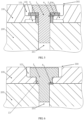
FIG. 2 is a schematic showing a fastening apparatus of a thrust pad according to embodiment one of the present disclosure. -
FIG. 3 is a schematic showing a fastening apparatus of a thrust pad according to embodiment two of the present disclosure. -
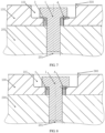
FIG. 4 is a schematic showing a fastening apparatus of a thrust pad according to embodiment three of the present disclosure. -
FIG. 5 is a schematic showing a fastening apparatus of a thrust pad according to embodiment four of the present disclosure. -
FIG. 6 is a schematic showing a fastening apparatus of a thrust pad according to embodiment five of the present disclosure. -
FIG. 7 is a schematic showing a fastening apparatus of a thrust pad according to embodiment six of the present disclosure. -
FIG. 8 is a schematic showing a fastening apparatus of a thrust pad according to embodiment seven of the present disclosure. -
- 100
- thrust pad
- 101
- first recess
- 102
- communication hole
- 103
- second recess
- 104
- annular cantilever structure
- 200
- carrying member
- 201
- threaded hole
- 300
- fastening apparatus
- 1
- bolt
- 11
- end cap
- 12
- screw
- 13
- shoulder
- 2
- flange pad
- 3
- bushing body
- A
- reserved gap
- The technical solutions in embodiments of the present disclosure are further described in detail hereinafter in conjunction with the drawings. Apparently, the embodiments described below are part, not all, of embodiments of the present disclosure.
- In the description of the present disclosure, unless otherwise expressly specified and limited, the term "connected to each other", "connected" or "secured" is to be construed in a broad sense, for example, as securely connected, detachably connected or integrated; mechanically connected or electrically connected; directly connected to each other or indirectly connected to each other via an intermediary; or internal connection between two components or interaction relations between two components. For those of ordinary skill in the art, specific meanings of the preceding terms in the present disclosure may be construed based on specific situations.
- In the present disclosure, unless otherwise expressly specified and limited, when a first feature is described as "above" or "below" a second feature, the first feature and the second feature may be in direct contact or be in contact via another feature between the two features. Moreover, when the first feature is described as "on", "above", or "over" the second feature, the first feature is right on, above, or over the second feature, the first feature is obliquely on, above, or over the second feature, or the first feature is simply at a higher level than the second feature. When the first feature is described as "under", "below", or "underneath" the second feature, the first feature is right under, below, or underneath the second feature, the first feature is obliquely under, below, or underneath the second feature, or the first feature is simply at a lower level than the second feature.
- This embodiment provides a gearbox. As shown in
FIG. 1 , the gearbox includes athrust pad 100, a carryingmember 200, and a fastening apparatus of a thrust pad. Thefastening apparatus 300 of a thrust pad is configured to connect thethrust pad 100 to the carryingmember 200. The carryingmember 200 may be a rotating stand. The carryingmember 200 may be set according to needs and is not limited. This embodiment provides a fastening apparatus of a thrust pad. As shown inFIGS. 1 and 2 , thethrust pad 100 is provided with afirst recess 101 and acommunication hole 102 communicating with thefirst recess 101. The carryingmember 200 is provided with a threadedhole 201. The aperture of thecommunication hole 102 is greater than the aperture of the threadedhole 201. Thefastening apparatus 300 includes abolt 1 and a connection structure. An end cap 11 of thebolt 1 is disposed in thefirst recess 101. Ascrew 12 of thebolt 1 passes through the connection structure and is threaded into the threadedhole 201. The connection structure is able to be clamped between the end cap 11 and the carryingmember 200. - The carrying
member 200 is provided with the threadedhole 201 to be connected to thebolt 1 in a threaded manner so as to mount and carry thethrust pad 100. Thebolt 1 presses and secures thethrust pad 100 on the carryingmember 200 through the connection structure. The connection structure is used for bearing the tightening torque of thebolt 1 directly, preventing thethrust pad 100 from directly bearing the full tightening torque of thebolt 1. Therefore, it guarantees that thethrust pad 100 has little to no plastic deformation, preventing thethrust pad 100 from being crushed, improving the tightening torque of thebolt 1 that can be born by thethrust pad 100, and compensating for the pre-tightening force loss of thebolt 1. The arrangement of the connection structure increases the function area of thebolt 1. Therefore, a greater pre-tightening force of thebolt 1 can be applied, thereby enabling various components that are connected to each other to be sufficiently stable and firm without looseness, overcoming the shortcoming that the existing mounting of thebolt 1 is easy to loosen. Thethrust pad 100 is fully secured on the carryingmember 200, avoiding the failure of the gearbox. - The carrying
member 200 may be a planet carrier or a gear. Thethrust pad 100 is disposed between the planet carrier and the gear. Thethrust pad 100 is connected to one of the planet carrier or the gear through the fastening apparatus of a thrust pad. - In an embodiment, the coefficient of thermal expansion of the
thrust pad 100 may be the same as, greater than, or less than the coefficient of thermal expansion of the material of thebolt 1. The material of thethrust pad 100 is not limited, improving the applicability of thefastening apparatus 300. - In an embodiment, the connection structure is disposed between the
thrust pad 100 and thebolt 1. Thethrust pad 100 is in indirect contact with thebolt 1 through the connection structure. - In an embodiment, as shown in
FIG. 2 , the connection structure includes aflange pad 2 and abushing body 3 that are connected to each other. Theflange pad 2 is disposed in thefirst recess 101. Thebushing body 3 is disposed in thecommunication hole 102. Theflange pad 2 is clamped between the end cap 11 and the bottom of thefirst recess 101. A reserved gap A is formed between thebushing body 3 and the carryingmember 200. Thebolt 1 applies a force to the bushing. After thebolt 1 is tightened, the reserved gap A is eliminated. A lower end face of the bushing is in contact with the carryingmember 200 to press thethrust pad 100 and secure thethrust pad 100 on the carryingmember 200. In design, the size tolerance of thebushing body 3 is controlled. In an original state, the lower end face of thebushing body 3 and a surface of the carryingmember 200 form the gap, that is, the reserved gap A. The size of the reserved gap A is greater than or equal to 0. The size of the reserved gap A is related to the magnitude of the tightening torque of thebolt 1 and is optionally determined by calculation to guarantee sufficient stable connection. The tightening torque of thebolt 1 is designated by adjusting the size of the reserved gap A, guaranteeing a sufficient clamping force and no looseness. Moreover, thebushing body 3 is supported between thebolt 1 and the carryingmember 200. Thethrust pad 100 is not in direct contact with thebolt 1 so that thethrust pad 100 has little to no plastic deformation, preventing thethrust pad 100 from being crushed. Additionally, thebolt 1 acts directly on theflange pad 2 and thebushing body 3 to be connected to the carryingmember 200. The contact area between theflange pad 2 and thethrust pad 100 is relatively increased. Therefore, a greater pre-tightening force of thebolt 1 can be applied, guaranteeing that various components are connected stably without looseness. - Optionally, the
flange pad 2 and thebushing body 3 are each provided with a through hole to facilitate the passage of thescrew 12. Thefirst recess 101 is a circular recess. The outer diameter of theflange pad 2 is less than the inner diameter of thefirst recess 101 so that theflange pad 2 is accommodated in thefirst recess 101. - In an embodiment, the
flange pad 2 and thebushing body 3 are integrally structured. For example, a flange bushing may be purchased, which is convenient and reliable. In other embodiments, theflange pad 2 and thebushing body 3 are separably structured. Theflange pad 2 and thebushing body 3 may be connected through, for example, bonding, welding or fastener connection. The connection may be set according to needs and is not limited. - This embodiment provides a fastening apparatus of a thrust pad. The fastening apparatus in this embodiment is the basically same as the structure in embodiment one, with no repetition of identical parts. A difference between this embodiment and the preceding embodiment lies in that, as shown in
FIG. 3 , thethrust pad 100 further includes asecond recess 103. Thefirst recess 101 and thesecond recess 103 communicate with two sides of thecommunication hole 102 respectively. The area of the bottom of thefirst recess 101 and the area of the bottom of thesecond recess 103 are each greater than the opening area of thecommunication hole 102. An opening of thesecond recess 103 faces the carryingmember 200. The connection structure includes aflange pad 2 and abushing body 3. Theflange pad 2 is disposed in thefirst recess 101. Thebushing body 3 is disposed in thecommunication hole 102. Theflange pad 2 is clamped between the end cap 11 and the bottom of thefirst recess 101. A reserved gap A is formed between the carryingmember 200 and thebushing body 3. - On the basis of embodiment one, the structure of the
thrust pad 100 is modified. Thefirst recess 101 and thesecond recess 103 form anannular cantilever structure 104 with a certain thickness at the periphery of thecommunication hole 102. Thethrust pad 100 forms a structure having an elastic rebound and may maintain the elastic deformation with a first amplitude. When temperatures fluctuate, thethrust pad 100 has enough elasticity and stability, further improving the firmness of securing thethrust pad 100 on the carryingmember 200. - This embodiment provides a fastening apparatus of a thrust pad. The fastening apparatus in this embodiment is the basically same as the structure in embodiment one. The same part is not repeated. A difference between this embodiment and the preceding embodiment lies in that, as shown in
FIG. 4 , the connection structure includes aflange pad 2 and abushing body 3. Theflange pad 2 is disposed in thefirst recess 101. Thebushing body 3 is disposed in thecommunication hole 102. Theflange pad 2 is clamped between the end cap 11 and the bottom of thefirst recess 101. One end of thebushing body 3 abuts against the carryingmember 200. A reserved gap A is formed between the other end of thebushing body 3 and theflange pad 2. - Optionally, the
flange pad 2 may be a metal pad with a certain thickness. An upper surface of the metal pad and a lower surface of the metal pad are in contact with the end cap 11 of thebolt 1 and thethrust pad 100 respectively. The lower surface of thepad 2 and an upper surface of the bushing form the gap. Thebolt 1 is not in direct contact with thethrust pad 100 and thebushing body 3 and acts directly on thepad 2. After the gap is consumed, the lower surface of thepad 2 is in contact with thebushing body 3 and presses thethrust pad 100. The existence of thepad 2 may get a greater pre-tightening force of thebolt 1 to be born, guaranteeing that various components are connected stably without looseness. Moreover, thebushing body 3 is supported between thepad 1 and the carryingmember 200, preventing thethrust pad 100 from being crushed. - This embodiment provides a fastening apparatus of a thrust pad. The fastening apparatus in this embodiment is the basically same as the structure in embodiment one. The same part is not repeated. A difference between this embodiment and the preceding embodiments lies in that, as shown in
FIG. 5 , thethrust pad 100 further includes asecond recess 103. Thefirst recess 101 and thesecond recess 103 communicate with two sides of thecommunication hole 102 respectively. The area of the bottom of thefirst recess 101 and the area of the bottom of thesecond recess 103 are each greater than the opening area of thecommunication hole 102. An opening of thesecond recess 103 faces the carryingmember 200. The connection structure includes aflange pad 2 and abushing body 3. Theflange pad 2 is disposed in thefirst recess 101. Thebushing body 3 is disposed in thecommunication hole 102. Theflange pad 2 is clamped between the end cap 11 and the bottom of thefirst recess 101. A reserved gap A is formed between theflange pad 2 and thebushing body 3. - On the basis of embodiment three, the structure of the
thrust pad 100 is modified. Thefirst recess 101 and thesecond recess 103 form anannular cantilever structure 104 with a certain thickness at the periphery of thecommunication hole 102. Thethrust pad 100 forms a structure having an elastic rebound and may maintain the elastic deformation with a certain amplitude. When temperature fluctuates, thethrust pad 100 has enough elasticity and stability, further improving the firmness of securing thethrust pad 100 on the carryingmember 200. - This embodiment provides a fastening apparatus of a thrust pad. The fastening apparatus in this embodiment is the basically same as the structure in embodiment one. The same part is not repeated. A difference between this embodiment and the preceding embodiments lies in that, as shown in
FIG. 6 , the connection structure and thebolt 1 are integrally structured. The connection structure is connected to an end of the end cap 11 facing thescrew 12. The end cap 11 abuts against the bottom of thefirst recess 101. The connection structure is disposed in thecommunication hole 102. A reserved gap A is formed between the carryingmember 200 and an end of the connection structure facing away from the end cap 11. - The connection structure and the
bolt 1 are integrated to form anon-standard bolt 1. The end cap 11 of thebolt 1 is in direct contact with thethrust pad 100. The connection structure is located between thescrew 12 and the end cap 11 to form a shoulder 13 with a plane. An end face of the shoulder 13 and a surface of the carryingmember 200 form the reserved gap A. Thebolt 1 is tightened. After the gap is consumed, the end face of the shoulder 13 is in contact with the carryingmember 200 and presses thethrust pad 100. The shoulder 13 is supported on the surface of the carryingmember 200, increasing the contact area between thebolt 1 and the carryingmember 200 and thrustpad 100, bearing a greater pre-tightening force of thebolt 1, guaranteeing that various components are connected stably without looseness, and preventing thethrust pad 100 from being crushed. - This embodiment provides a fastening apparatus of a thrust pad. The fastening apparatus in this embodiment is the basically same as the structure in embodiment one. The same part is not repeated. A difference between this embodiment and the preceding embodiment lies in that, as shown in
FIG. 7 , the connection structure includes abushing body 3. Thebushing body 3 passes through thecommunication hole 102. Thescrew 12 passes through thebushing body 3. Two ends of thebushing body 3 abut against the end cap 11 and the carryingmember 200 respectively. A reserved gap A is formed between the end cap 11 and the bottom of thefirst recess 101. - An upper surface of the
bushing body 3 and a lower surface of thebushing body 3 are in contact with the end cap 11 of thebolt 1 and the carryingmember 200 respectively. The height of thebushing body 3 is greater than the depth of thecommunication hole 102 so that the reserved gap A is formed between a lower end face of the end cap 11 of thebolt 1 and the bottom of thefirst recess 101 of thethrust pad 100. Thebolt 1 is not in direct contact with thethrust pad 100 and acts directly on thebushing body 3. After the gap is consumed, a lower end surface of thebolt 1 is in contact with thethrust pad 100, pressing thethrust pad 100. The tightening torque of thebolt 1 is designated by adjusting the size of the gap, guaranteeing that various components are connected stably without looseness. Moreover, thebushing body 3 is supported between the end cap 11 of thebolt 1 and the carryingmember 200 so as to carry part of the tightening torque of thebolt 1, preventing thethrust pad 100 from being crushed. - This embodiment provides a fastening apparatus of a thrust pad. The fastening apparatus in this embodiment is the basically same as the structure in embodiment one with no repetition of identical parts. A difference between this embodiment and the preceding embodiments lies in that, as shown in
FIG. 8 , the connection structure includes abushing body 3. Thebushing body 3 passes through thecommunication hole 102. Thescrew 12 passes through thebushing body 3. One end of thebushing body 3 abuts against the carryingmember 200. The end cap 11 abuts against the bottom of thefirst recess 101. A reserved gap A is formed between the other end of thebushing body 3 and the end cap 11. - The height of the
bushing body 3 is less than the depth of thecommunication hole 102 so that a lower end face of the end cap 11 of thebolt 1 and an upper surface of thebushing body 3 form the gap. In an original state, thebolt 1 is in direct contact with thethrust pad 100. Thebolt 1 is tightened. After thethrust pad 100 is deformed and the gap is consumed, the lower end face of the end cap 11 of thebolt 1 is in contact with the bushing, pressing thethrust pad 100. The tightening torque of thebolt 1 is designated by adjusting the size of the gap, guaranteeing that various components are connected stably without looseness. Moreover, thebushing body 3 is supported between the end cap 11 of thebolt 1 and the carryingmember 200 so as to carry part of the tightening torque of thebolt 1, preventing thethrust pad 100 from being crushed.
For the fastening apparatus of a thrust pad and the gearbox provided in the present disclosure, the carrying member is provided with the threaded hole to be connected to the bolt in a threaded manner so as to mount and carry the thrust pad. The bolt presses and secures the thrust pad on the carrying member through the connection structure. The connection structure is used for bearing the tightening torque of the bolt directly, preventing the thrust pad from directly bearing the full tightening torque of the bolt. Therefore, it guarantees that the thrust pad has little to no plastic deformation, preventing the thrust pad from being crushed, improving the tightening torque of the bolt that can be born by the thrust pad, and compensating for the pre-tightening force of the bolt. The arrangement of the connection structure increases the function area of the bolt. Therefore, a greater pre-tightening force of the bolt can be applied, thereby enabling various components that are connected to each other to be sufficiently stable and firm without looseness, overcoming the shortcoming that the existing mounting of the bolt is easy to loosen. The thrust pad is fully secured on the carrying member, avoiding the failure of the gearbox.
Claims (10)
- A fastening apparatus, for connecting a thrust pad (100) to a carrying member (200), wherein the thrust pad (100) is provided with a first recess (101) and a communication hole (102) communicating with the first recess (101), the carrying member (200) is provided with a threaded hole (201), an aperture of the communication hole (102) is greater than an aperture of the threaded hole (201), the fastening apparatus comprises a bolt (1) and a connection structure, an end cap (11) of the bolt (1) is disposed in the first recess (101), a screw (12) of the bolt (1) passes through the connection structure and is threaded into the threaded hole (201), and the connection structure is able to be clamped between the end cap (11) and the carrying member (200).
- The fastening apparatus according to claim 1, wherein the connection structure comprises a flange pad (2) and a bushing body (3) that are connected to each other, the flange pad (2) is disposed in the first recess (101), the bushing body (3) is disposed in the communication hole (102), the flange pad (2) is clamped between the end cap (11) and a bottom of the first recess (101), and a reserved gap (A) is formed between the bushing body (3) and the carrying member (200).
- The fastening apparatus according to claim 2, wherein the flange pad (2) and the bushing body (3) are integrally structured, or the flange pad (2) and the bushing body (3) are separably structured.
- The fastening apparatus according to claim 1, wherein the connection structure comprises a flange pad (2) and a bushing body (3), the flange pad (2) is disposed in the first recess (101), the bushing body (3) is disposed in the communication hole (102), the flange pad (2) is clamped between the end cap (11) and a bottom of the first recess (101), one end of the bushing body (3) abuts against the carrying member (200), and a reserved gap (A) is formed between another end of the bushing body (3) and the flange pad (2).
- The fastening apparatus according to claim 1, wherein the thrust pad (100) further comprises a second recess (103), the first recess (101) and the second recess (103) communicate with two sides of the communication hole (102) respectively, an area of a bottom of the first recess (101) and an area of a bottom of the second recess (103) are each greater than an opening area of the communication hole (102), and an opening of the second recess (103) faces the carrying member (200); and
the connection structure comprises a flange pad (2) and a bushing body (3), the flange pad (2) is disposed in the first recess (101), the bushing body (3) is disposed in the communication hole (102), the flange pad (2) is clamped between the end cap (11) and the bottom of the first recess (101), and a reserved gap (A) is formed between the bushing body (3) and one of the carrying member (200) or the flange pad (2). - The fastening apparatus according to claim 1, wherein the connection structure and the bolt (1) are integrally structured, the connection structure is connected to an end of the end cap (11) facing the screw (12), the end cap (11) abuts against a bottom of the first recess (101), the connection structure is disposed in the communication hole (102), and a reserved gap (A) is formed between the carrying member (200) and an end of the connection structure facing away from the end cap (11).
- The fastening apparatus according to claim 1, wherein the connection structure comprises a bushing body (3), the bushing body (3) passes through the communication hole (102), the screw (12) passes through the bushing body (3), two ends of the bushing body (3) abut against the end cap (11) and the carrying member (200) respectively, and a reserved gap (A) is formed between the end cap (11) and a bottom of the first recess (101).
- The fastening apparatus according to claim 1, wherein the connection structure comprises a bushing body (3), the bushing body (3) passes through the communication hole (102), the screw (12) passes through the bushing body (3), one end of the bushing body (3) abuts against the carrying member (200), the end cap (11) abuts against a bottom of the first recess (101), and a reserved gap (A) is formed between another end of the bushing body (3) and the end cap (11).
- The fastening apparatus according to any one of claims 2 to 8, wherein a size of the reserved gap (A) is greater than or equal to 0.
- A gearbox, comprising a thrust pad (100), a carrying member (200), and the fastening apparatus according to any one of claims 1 to 9, wherein the fastening apparatus is configured to connect the thrust pad (100) to the carrying member (200).
Applications Claiming Priority (1)
| Application Number | Priority Date | Filing Date | Title |
|---|---|---|---|
| CN202310040728.6A CN116255399A (en) | 2023-01-13 | 2023-01-13 | Fastening device and gear box for thrust tile |
Publications (2)
| Publication Number | Publication Date |
|---|---|
| EP4400734A1 true EP4400734A1 (en) | 2024-07-17 |
| EP4400734B1 EP4400734B1 (en) | 2025-08-27 |
Family
ID=86685625
Family Applications (1)
| Application Number | Title | Priority Date | Filing Date |
|---|---|---|---|
| EP23220697.9A Active EP4400734B1 (en) | 2023-01-13 | 2023-12-29 | Fastening apparatus and gearbox |
Country Status (6)
| Country | Link |
|---|---|
| US (1) | US20240240706A1 (en) |
| EP (1) | EP4400734B1 (en) |
| CN (1) | CN116255399A (en) |
| DK (1) | DK4400734T3 (en) |
| ES (1) | ES3046708T3 (en) |
| FI (1) | FI4400734T3 (en) |
Citations (3)
| Publication number | Priority date | Publication date | Assignee | Title |
|---|---|---|---|---|
| GB201459A (en) * | 1922-10-20 | 1923-08-02 | Charles William Alexander Tayl | Improvements in or relating to bearings |
| WO2010022778A1 (en) * | 2008-08-28 | 2010-03-04 | Maag Gear Ag | Axial plain bearing and bearing segment for the same |
| CN212509218U (en) * | 2020-07-31 | 2021-02-09 | 福建福清核电有限公司 | Elastic support of thrust bearing |
Family Cites Families (17)
| Publication number | Priority date | Publication date | Assignee | Title |
|---|---|---|---|---|
| US4732519A (en) * | 1986-12-24 | 1988-03-22 | Illinois Tool Works Inc. | Fastener assembly with axial play |
| DE3804886A1 (en) * | 1988-02-17 | 1989-08-31 | Freudenberg Carl Fa | BUSHING BEARING |
| DE4036050C1 (en) * | 1990-11-13 | 1992-04-09 | Lemfoerder Metallwaren Ag, 2844 Lemfoerde, De | |
| US5244325A (en) * | 1992-09-28 | 1993-09-14 | Elco Industries, Inc. | Fastener assembly with axially slidable sleeve |
| US6059503A (en) * | 1998-10-27 | 2000-05-09 | Johnson; H. Thad | Captivated fastener assembly |
| JP2001263314A (en) * | 2000-03-17 | 2001-09-26 | Honda Motor Co Ltd | Bolt fastening structure of magnesium alloy member |
| JP4730217B2 (en) * | 2006-06-12 | 2011-07-20 | トヨタ自動車株式会社 | Fastening structure including flanged collar |
| DE102010006891A1 (en) * | 2009-09-02 | 2011-03-03 | Josef Kuboth | Screw connector for connecting pre-welding flanges utilized for connecting components e.g. containers, during system construction, has outer sleeve whose heat expansion corresponds to sum of heat expansion of inner sleeve and screw |
| CN102141073B (en) * | 2011-01-13 | 2012-10-10 | 西北工业大学 | High-temperature self-fastening connection device |
| CN203528243U (en) * | 2013-10-31 | 2014-04-09 | 中国重汽集团济南动力有限公司 | End part connecting structure of transverse stabilizer bar of car |
| CN204357929U (en) * | 2014-12-30 | 2015-05-27 | 湖南崇德工业科技有限公司 | A kind of thrust bearing shoe valve limited support structure |
| CN208686934U (en) * | 2018-08-15 | 2019-04-02 | 柳工柳州传动件有限公司 | Planetary gear axial direction position limiting structure |
| CN109764034A (en) * | 2019-02-25 | 2019-05-17 | 江苏康迅数控装备科技有限公司 | A kind of invisible connecting piece |
| AT523760B1 (en) * | 2020-04-15 | 2022-06-15 | Miba Gleitlager Austria Gmbh | Assembly of components, and a wind turbine in which the assembly of components is installed |
| JP7523980B2 (en) * | 2020-07-20 | 2024-07-29 | ナブテスコ株式会社 | Reduction mechanism and drive device |
| CN216554864U (en) * | 2021-11-12 | 2022-05-17 | 苏州中成新能源科技股份有限公司 | Bolt for front cover of compressor |
| CN217107832U (en) * | 2022-01-24 | 2022-08-02 | 麻栗坡县水电开发有限公司 | Device for preventing thrust bearing bush from being overhigh in temperature in hydropower station |
-
2023
- 2023-01-13 CN CN202310040728.6A patent/CN116255399A/en active Pending
- 2023-12-26 US US18/395,875 patent/US20240240706A1/en active Pending
- 2023-12-29 ES ES23220697T patent/ES3046708T3/en active Active
- 2023-12-29 FI FIEP23220697.9T patent/FI4400734T3/en active
- 2023-12-29 EP EP23220697.9A patent/EP4400734B1/en active Active
- 2023-12-29 DK DK23220697.9T patent/DK4400734T3/en active
Patent Citations (3)
| Publication number | Priority date | Publication date | Assignee | Title |
|---|---|---|---|---|
| GB201459A (en) * | 1922-10-20 | 1923-08-02 | Charles William Alexander Tayl | Improvements in or relating to bearings |
| WO2010022778A1 (en) * | 2008-08-28 | 2010-03-04 | Maag Gear Ag | Axial plain bearing and bearing segment for the same |
| CN212509218U (en) * | 2020-07-31 | 2021-02-09 | 福建福清核电有限公司 | Elastic support of thrust bearing |
Also Published As
| Publication number | Publication date |
|---|---|
| EP4400734B1 (en) | 2025-08-27 |
| CN116255399A (en) | 2023-06-13 |
| DK4400734T3 (en) | 2025-11-03 |
| ES3046708T3 (en) | 2025-12-02 |
| US20240240706A1 (en) | 2024-07-18 |
| FI4400734T3 (en) | 2025-10-29 |
Similar Documents
| Publication | Publication Date | Title |
|---|---|---|
| US6174117B1 (en) | Fastening structure including a bolt having a serration that is press-fit into a bolt hole of a flange | |
| US4863329A (en) | Resiliently clamped support | |
| US12038035B2 (en) | Threaded fastener | |
| KR19990072188A (en) | Rectifying diode | |
| CN110088490A (en) | Externally threaded parts | |
| US20240240706A1 (en) | Fastening Apparatus and Gearbox | |
| US7614277B2 (en) | Knock sensor | |
| CN115020777A (en) | Fuel cell stack pressing device and fuel cell | |
| TW202348495A (en) | Drive arrangement | |
| US4934857A (en) | Co-conic fastener and fastening method | |
| US20070284198A1 (en) | Disc brake, in particular for a utility vehicle | |
| CN101776117A (en) | Anti-loosening method for connection between round nut and bolt | |
| CN114072589B (en) | Bearing assembly for thrust bearing | |
| CN209800512U (en) | Component Connection Mechanism with Gap Compensation Structure | |
| US20040066106A1 (en) | Plastic fastener | |
| JP2001271820A (en) | Locking nut | |
| JPS63176876A (en) | Laminated metal ring | |
| US20220068762A1 (en) | Semiconductor device and semiconductor device with cooling member | |
| JPH11294474A (en) | Fastening method and bearing fastening method | |
| CN220488132U (en) | Bearing outer ring fastening thread ring | |
| CN219905372U (en) | Fan variable pitch bearing oil collecting bottle with bottle cap self-locking structure | |
| CN215763348U (en) | Internal part structure and butterfly valve comprising same | |
| CN223436768U (en) | Connector assembly for connecting battery terminals | |
| CN223035489U (en) | Slot type fastening bolt set | |
| CN219535731U (en) | Shaft mounting structure |
Legal Events
| Date | Code | Title | Description |
|---|---|---|---|
| PUAI | Public reference made under article 153(3) epc to a published international application that has entered the european phase |
Free format text: ORIGINAL CODE: 0009012 |
|
| STAA | Information on the status of an ep patent application or granted ep patent |
Free format text: STATUS: REQUEST FOR EXAMINATION WAS MADE |
|
| 17P | Request for examination filed |
Effective date: 20231229 |
|
| AK | Designated contracting states |
Kind code of ref document: A1 Designated state(s): AL AT BE BG CH CY CZ DE DK EE ES FI FR GB GR HR HU IE IS IT LI LT LU LV MC ME MK MT NL NO PL PT RO RS SE SI SK SM TR |
|
| STAA | Information on the status of an ep patent application or granted ep patent |
Free format text: STATUS: EXAMINATION IS IN PROGRESS |
|
| 17Q | First examination report despatched |
Effective date: 20250303 |
|
| GRAP | Despatch of communication of intention to grant a patent |
Free format text: ORIGINAL CODE: EPIDOSNIGR1 |
|
| STAA | Information on the status of an ep patent application or granted ep patent |
Free format text: STATUS: GRANT OF PATENT IS INTENDED |
|
| INTG | Intention to grant announced |
Effective date: 20250519 |
|
| GRAS | Grant fee paid |
Free format text: ORIGINAL CODE: EPIDOSNIGR3 |
|
| GRAA | (expected) grant |
Free format text: ORIGINAL CODE: 0009210 |
|
| STAA | Information on the status of an ep patent application or granted ep patent |
Free format text: STATUS: THE PATENT HAS BEEN GRANTED |
|
| AK | Designated contracting states |
Kind code of ref document: B1 Designated state(s): AL AT BE BG CH CY CZ DE DK EE ES FI FR GB GR HR HU IE IS IT LI LT LU LV MC ME MK MT NL NO PL PT RO RS SE SI SK SM TR |
|
| REG | Reference to a national code |
Ref country code: CH Ref legal event code: EP |
|
| REG | Reference to a national code |
Ref country code: DE Ref legal event code: R096 Ref document number: 602023006139 Country of ref document: DE |
|
| REG | Reference to a national code |
Ref country code: IE Ref legal event code: FG4D |
|
| REG | Reference to a national code |
Ref country code: FI Ref legal event code: FGE |
|
| REG | Reference to a national code |
Ref country code: DK Ref legal event code: T3 Effective date: 20251029 |
|
| REG | Reference to a national code |
Ref country code: ES Ref legal event code: FG2A Ref document number: 3046708 Country of ref document: ES Kind code of ref document: T3 Effective date: 20251202 |
|
| REG | Reference to a national code |
Ref country code: NL Ref legal event code: MP Effective date: 20250827 |
|
| PG25 | Lapsed in a contracting state [announced via postgrant information from national office to epo] |
Ref country code: IS Free format text: LAPSE BECAUSE OF FAILURE TO SUBMIT A TRANSLATION OF THE DESCRIPTION OR TO PAY THE FEE WITHIN THE PRESCRIBED TIME-LIMIT Effective date: 20251227 |
|
| PGFP | Annual fee paid to national office [announced via postgrant information from national office to epo] |
Ref country code: DE Payment date: 20251211 Year of fee payment: 3 |
|
| PG25 | Lapsed in a contracting state [announced via postgrant information from national office to epo] |
Ref country code: NO Free format text: LAPSE BECAUSE OF FAILURE TO SUBMIT A TRANSLATION OF THE DESCRIPTION OR TO PAY THE FEE WITHIN THE PRESCRIBED TIME-LIMIT Effective date: 20251127 |
|
| REG | Reference to a national code |
Ref country code: LT Ref legal event code: MG9D |
|
| PG25 | Lapsed in a contracting state [announced via postgrant information from national office to epo] |
Ref country code: PT Free format text: LAPSE BECAUSE OF FAILURE TO SUBMIT A TRANSLATION OF THE DESCRIPTION OR TO PAY THE FEE WITHIN THE PRESCRIBED TIME-LIMIT Effective date: 20251229 |
|
| PGFP | Annual fee paid to national office [announced via postgrant information from national office to epo] |
Ref country code: FI Payment date: 20251224 Year of fee payment: 3 Ref country code: DK Payment date: 20251224 Year of fee payment: 3 |
|
| PG25 | Lapsed in a contracting state [announced via postgrant information from national office to epo] |
Ref country code: HR Free format text: LAPSE BECAUSE OF FAILURE TO SUBMIT A TRANSLATION OF THE DESCRIPTION OR TO PAY THE FEE WITHIN THE PRESCRIBED TIME-LIMIT Effective date: 20250827 Ref country code: NL Free format text: LAPSE BECAUSE OF FAILURE TO SUBMIT A TRANSLATION OF THE DESCRIPTION OR TO PAY THE FEE WITHIN THE PRESCRIBED TIME-LIMIT Effective date: 20250827 |
|
| PG25 | Lapsed in a contracting state [announced via postgrant information from national office to epo] |
Ref country code: GR Free format text: LAPSE BECAUSE OF FAILURE TO SUBMIT A TRANSLATION OF THE DESCRIPTION OR TO PAY THE FEE WITHIN THE PRESCRIBED TIME-LIMIT Effective date: 20251128 |
|
| PG25 | Lapsed in a contracting state [announced via postgrant information from national office to epo] |
Ref country code: SE Free format text: LAPSE BECAUSE OF FAILURE TO SUBMIT A TRANSLATION OF THE DESCRIPTION OR TO PAY THE FEE WITHIN THE PRESCRIBED TIME-LIMIT Effective date: 20250827 |
|
| PG25 | Lapsed in a contracting state [announced via postgrant information from national office to epo] |
Ref country code: LV Free format text: LAPSE BECAUSE OF FAILURE TO SUBMIT A TRANSLATION OF THE DESCRIPTION OR TO PAY THE FEE WITHIN THE PRESCRIBED TIME-LIMIT Effective date: 20250827 |
|
| PG25 | Lapsed in a contracting state [announced via postgrant information from national office to epo] |
Ref country code: PL Free format text: LAPSE BECAUSE OF FAILURE TO SUBMIT A TRANSLATION OF THE DESCRIPTION OR TO PAY THE FEE WITHIN THE PRESCRIBED TIME-LIMIT Effective date: 20250827 Ref country code: BG Free format text: LAPSE BECAUSE OF FAILURE TO SUBMIT A TRANSLATION OF THE DESCRIPTION OR TO PAY THE FEE WITHIN THE PRESCRIBED TIME-LIMIT Effective date: 20250827 |
|
| PG25 | Lapsed in a contracting state [announced via postgrant information from national office to epo] |
Ref country code: RS Free format text: LAPSE BECAUSE OF FAILURE TO SUBMIT A TRANSLATION OF THE DESCRIPTION OR TO PAY THE FEE WITHIN THE PRESCRIBED TIME-LIMIT Effective date: 20251127 |
|
| REG | Reference to a national code |
Ref country code: AT Ref legal event code: MK05 Ref document number: 1830214 Country of ref document: AT Kind code of ref document: T Effective date: 20250827 |
|
| PG25 | Lapsed in a contracting state [announced via postgrant information from national office to epo] |
Ref country code: RO Free format text: LAPSE BECAUSE OF FAILURE TO SUBMIT A TRANSLATION OF THE DESCRIPTION OR TO PAY THE FEE WITHIN THE PRESCRIBED TIME-LIMIT Effective date: 20250827 |
|
| PG25 | Lapsed in a contracting state [announced via postgrant information from national office to epo] |
Ref country code: SM Free format text: LAPSE BECAUSE OF FAILURE TO SUBMIT A TRANSLATION OF THE DESCRIPTION OR TO PAY THE FEE WITHIN THE PRESCRIBED TIME-LIMIT Effective date: 20250827 |
|
| PGFP | Annual fee paid to national office [announced via postgrant information from national office to epo] |
Ref country code: ES Payment date: 20260130 Year of fee payment: 3 |
|
| PG25 | Lapsed in a contracting state [announced via postgrant information from national office to epo] |
Ref country code: AT Free format text: LAPSE BECAUSE OF FAILURE TO SUBMIT A TRANSLATION OF THE DESCRIPTION OR TO PAY THE FEE WITHIN THE PRESCRIBED TIME-LIMIT Effective date: 20250827 |
|
| PG25 | Lapsed in a contracting state [announced via postgrant information from national office to epo] |
Ref country code: IT Free format text: LAPSE BECAUSE OF FAILURE TO SUBMIT A TRANSLATION OF THE DESCRIPTION OR TO PAY THE FEE WITHIN THE PRESCRIBED TIME-LIMIT Effective date: 20250827 |
|
| PG25 | Lapsed in a contracting state [announced via postgrant information from national office to epo] |
Ref country code: CZ Free format text: LAPSE BECAUSE OF FAILURE TO SUBMIT A TRANSLATION OF THE DESCRIPTION OR TO PAY THE FEE WITHIN THE PRESCRIBED TIME-LIMIT Effective date: 20250827 |
|
| PG25 | Lapsed in a contracting state [announced via postgrant information from national office to epo] |
Ref country code: SK Free format text: LAPSE BECAUSE OF FAILURE TO SUBMIT A TRANSLATION OF THE DESCRIPTION OR TO PAY THE FEE WITHIN THE PRESCRIBED TIME-LIMIT Effective date: 20250827 Ref country code: EE Free format text: LAPSE BECAUSE OF FAILURE TO SUBMIT A TRANSLATION OF THE DESCRIPTION OR TO PAY THE FEE WITHIN THE PRESCRIBED TIME-LIMIT Effective date: 20250827 |