EP4400724A1 - Compressor - Google Patents
Compressor Download PDFInfo
- Publication number
- EP4400724A1 EP4400724A1 EP22895432.7A EP22895432A EP4400724A1 EP 4400724 A1 EP4400724 A1 EP 4400724A1 EP 22895432 A EP22895432 A EP 22895432A EP 4400724 A1 EP4400724 A1 EP 4400724A1
- Authority
- EP
- European Patent Office
- Prior art keywords
- oil
- oil return
- return pipe
- housing
- fixed
- Prior art date
- Legal status (The legal status is an assumption and is not a legal conclusion. Google has not performed a legal analysis and makes no representation as to the accuracy of the status listed.)
- Granted
Links
Images




Classifications
-
- F—MECHANICAL ENGINEERING; LIGHTING; HEATING; WEAPONS; BLASTING
- F04—POSITIVE - DISPLACEMENT MACHINES FOR LIQUIDS; PUMPS FOR LIQUIDS OR ELASTIC FLUIDS
- F04B—POSITIVE-DISPLACEMENT MACHINES FOR LIQUIDS; PUMPS
- F04B39/00—Component parts, details, or accessories, of pumps or pumping systems specially adapted for elastic fluids, not otherwise provided for in, or of interest apart from, groups F04B25/00 - F04B37/00
- F04B39/02—Lubrication
-
- F—MECHANICAL ENGINEERING; LIGHTING; HEATING; WEAPONS; BLASTING
- F04—POSITIVE - DISPLACEMENT MACHINES FOR LIQUIDS; PUMPS FOR LIQUIDS OR ELASTIC FLUIDS
- F04C—ROTARY-PISTON, OR OSCILLATING-PISTON, POSITIVE-DISPLACEMENT MACHINES FOR LIQUIDS; ROTARY-PISTON, OR OSCILLATING-PISTON, POSITIVE-DISPLACEMENT PUMPS
- F04C18/00—Rotary-piston pumps specially adapted for elastic fluids
- F04C18/02—Rotary-piston pumps specially adapted for elastic fluids of arcuate-engagement type, i.e. with circular translatory movement of co-operating members, each member having the same number of teeth or tooth-equivalents
- F04C18/0207—Rotary-piston pumps specially adapted for elastic fluids of arcuate-engagement type, i.e. with circular translatory movement of co-operating members, each member having the same number of teeth or tooth-equivalents both members having co-operating elements in spiral form
- F04C18/0215—Rotary-piston pumps specially adapted for elastic fluids of arcuate-engagement type, i.e. with circular translatory movement of co-operating members, each member having the same number of teeth or tooth-equivalents both members having co-operating elements in spiral form where only one member is moving
-
- F—MECHANICAL ENGINEERING; LIGHTING; HEATING; WEAPONS; BLASTING
- F04—POSITIVE - DISPLACEMENT MACHINES FOR LIQUIDS; PUMPS FOR LIQUIDS OR ELASTIC FLUIDS
- F04C—ROTARY-PISTON, OR OSCILLATING-PISTON, POSITIVE-DISPLACEMENT MACHINES FOR LIQUIDS; ROTARY-PISTON, OR OSCILLATING-PISTON, POSITIVE-DISPLACEMENT PUMPS
- F04C23/00—Combinations of two or more pumps, each being of rotary-piston or oscillating-piston type, specially adapted for elastic fluids; Pumping installations specially adapted for elastic fluids; Multi-stage pumps specially adapted for elastic fluids
- F04C23/005—Combinations of two or more pumps, each being of rotary-piston or oscillating-piston type, specially adapted for elastic fluids; Pumping installations specially adapted for elastic fluids; Multi-stage pumps specially adapted for elastic fluids of dissimilar working principle
-
- F—MECHANICAL ENGINEERING; LIGHTING; HEATING; WEAPONS; BLASTING
- F04—POSITIVE - DISPLACEMENT MACHINES FOR LIQUIDS; PUMPS FOR LIQUIDS OR ELASTIC FLUIDS
- F04C—ROTARY-PISTON, OR OSCILLATING-PISTON, POSITIVE-DISPLACEMENT MACHINES FOR LIQUIDS; ROTARY-PISTON, OR OSCILLATING-PISTON, POSITIVE-DISPLACEMENT PUMPS
- F04C23/00—Combinations of two or more pumps, each being of rotary-piston or oscillating-piston type, specially adapted for elastic fluids; Pumping installations specially adapted for elastic fluids; Multi-stage pumps specially adapted for elastic fluids
- F04C23/008—Hermetic pumps
-
- F—MECHANICAL ENGINEERING; LIGHTING; HEATING; WEAPONS; BLASTING
- F04—POSITIVE - DISPLACEMENT MACHINES FOR LIQUIDS; PUMPS FOR LIQUIDS OR ELASTIC FLUIDS
- F04C—ROTARY-PISTON, OR OSCILLATING-PISTON, POSITIVE-DISPLACEMENT MACHINES FOR LIQUIDS; ROTARY-PISTON, OR OSCILLATING-PISTON, POSITIVE-DISPLACEMENT PUMPS
- F04C29/00—Component parts, details or accessories of pumps or pumping installations, not provided for in groups F04C18/00 - F04C28/00
- F04C29/02—Lubrication; Lubricant separation
- F04C29/028—Means for improving or restricting lubricant flow
-
- F—MECHANICAL ENGINEERING; LIGHTING; HEATING; WEAPONS; BLASTING
- F04—POSITIVE - DISPLACEMENT MACHINES FOR LIQUIDS; PUMPS FOR LIQUIDS OR ELASTIC FLUIDS
- F04C—ROTARY-PISTON, OR OSCILLATING-PISTON, POSITIVE-DISPLACEMENT MACHINES FOR LIQUIDS; ROTARY-PISTON, OR OSCILLATING-PISTON, POSITIVE-DISPLACEMENT PUMPS
- F04C18/00—Rotary-piston pumps specially adapted for elastic fluids
- F04C18/30—Rotary-piston pumps specially adapted for elastic fluids having the characteristics covered by two or more of groups F04C18/02, F04C18/08, F04C18/22, F04C18/24, F04C18/48, or having the characteristics covered by one of these groups together with some other type of movement between co-operating members
- F04C18/34—Rotary-piston pumps specially adapted for elastic fluids having the characteristics covered by two or more of groups F04C18/02, F04C18/08, F04C18/22, F04C18/24, F04C18/48, or having the characteristics covered by one of these groups together with some other type of movement between co-operating members having the movement defined in group F04C18/08 or F04C18/22 and relative reciprocation between the co-operating members
- F04C18/356—Rotary-piston pumps specially adapted for elastic fluids having the characteristics covered by two or more of groups F04C18/02, F04C18/08, F04C18/22, F04C18/24, F04C18/48, or having the characteristics covered by one of these groups together with some other type of movement between co-operating members having the movement defined in group F04C18/08 or F04C18/22 and relative reciprocation between the co-operating members with vanes reciprocating with respect to the outer member
-
- F—MECHANICAL ENGINEERING; LIGHTING; HEATING; WEAPONS; BLASTING
- F04—POSITIVE - DISPLACEMENT MACHINES FOR LIQUIDS; PUMPS FOR LIQUIDS OR ELASTIC FLUIDS
- F04C—ROTARY-PISTON, OR OSCILLATING-PISTON, POSITIVE-DISPLACEMENT MACHINES FOR LIQUIDS; ROTARY-PISTON, OR OSCILLATING-PISTON, POSITIVE-DISPLACEMENT PUMPS
- F04C2240/00—Components
- F04C2240/80—Other components
- F04C2240/806—Pipes for fluids; Fittings therefor
-
- F—MECHANICAL ENGINEERING; LIGHTING; HEATING; WEAPONS; BLASTING
- F04—POSITIVE - DISPLACEMENT MACHINES FOR LIQUIDS; PUMPS FOR LIQUIDS OR ELASTIC FLUIDS
- F04C—ROTARY-PISTON, OR OSCILLATING-PISTON, POSITIVE-DISPLACEMENT MACHINES FOR LIQUIDS; ROTARY-PISTON, OR OSCILLATING-PISTON, POSITIVE-DISPLACEMENT PUMPS
- F04C2240/00—Components
- F04C2240/80—Other components
- F04C2240/809—Lubricant sump
-
- F—MECHANICAL ENGINEERING; LIGHTING; HEATING; WEAPONS; BLASTING
- F04—POSITIVE - DISPLACEMENT MACHINES FOR LIQUIDS; PUMPS FOR LIQUIDS OR ELASTIC FLUIDS
- F04C—ROTARY-PISTON, OR OSCILLATING-PISTON, POSITIVE-DISPLACEMENT MACHINES FOR LIQUIDS; ROTARY-PISTON, OR OSCILLATING-PISTON, POSITIVE-DISPLACEMENT PUMPS
- F04C2270/00—Control; Monitoring or safety arrangements
- F04C2270/12—Vibration
Definitions
- the present disclosure relates to a compressor, and more specifically, to a compressor including an oil return pipe that returns oil to an oil reservoir in a housing.
- a refrigerant discharged from a compressor that compresses the refrigerant inevitably contains oil used for lubrication. Since the discharge oil discharged together with the refrigerant in this way causes a decrease in performance of a heat exchanger, a reduction in discharge oil amount is desired.
- PTL 1 discloses that an oil discharge pipe for returning the oil supplied to a sliding portion of a compression mechanism portion to an oil reservoir in a lower portion of a housing is provided in the housing.
- an outer diameter of a central portion of the oil discharge pipe is made larger than that of other portions in order to reduce vibration of the oil discharge pipe.
- the vibration is reduced by making the outer diameter of the central portion larger than the other portions.
- the oil discharge pipe has a special shape, which is not preferable in terms of cost.
- the present disclosure has been made in view of such circumstances, and an object thereof is to provide a compressor capable of reducing vibration of an oil return pipe that returns oil to an oil reservoir in a housing with a simpler configuration.
- a compressor including: a rotary shaft portion that is rotationally driven; a compression mechanism that is connected to one end of the rotary shaft portion and compresses a refrigerant; a bearing portion that supports the rotary shaft portion; a housing that accommodates the rotary shaft portion, the compression mechanism, and the bearing portion and has an oil reservoir in a lower portion; and an oil return pipe that is provided in the housing and has one end fixed to the bearing portion and the other end extending toward the oil reservoir such that oil held in the bearing portion is returned to the oil reservoir, in which a plurality of the oil return pipes are provided in parallel such that longitudinal axes thereof are parallel to each other, and the oil return pipes are bundled.
- the vibration of the oil return pipe can be reduced with a simple configuration in which a plurality of oil return pipes are bundled.
- a compressor 1 is used for an air conditioner and compresses a refrigerant R, which is, for example, a gas such as carbon dioxide, in two stages.
- the compressor 1 is fixed to an installation surface FL via leg portions 3.
- the compressor 1 includes a housing 11 and includes a rotary compression mechanism (low-stage-side compression mechanism) 12, a scroll compression mechanism (high-stage-side compression mechanism) 13, an electric motor 14, and a rotary shaft (rotary shaft portion) 15, which are provided inside the housing 11.
- the housing 11 has a main body portion 21 having a cylindrical shape, and an upper cover portion 22 and a lower cover portion 23 that close upper and lower openings of the main body portion 21.
- the inside of the housing 11 forms a sealed space.
- the rotary shaft 15 is provided to extend vertically along an axis X inside the housing 11. An upper end (one end) side of the rotary shaft 15 is rotatably supported by an upper bearing 31. A lower end (other end) side of the rotary shaft 15 is rotatably supported by a lower bearing 32.
- the electric motor 14 is disposed at a center of the rotary shaft 15 in a longitudinal direction and on an outer peripheral side of the rotary shaft 15, and rotates the rotary shaft 15 around the axis X.
- the electric motor 14 includes a rotor 38 fixed to an outer peripheral surface of the rotary shaft 15, and a stator 39 that faces the rotor 38 in a radial direction with a gap from an outer peripheral surface of the rotor 38 and that is fixed to an inner wall of the main body portion 21 of the housing 11 by shrink fitting or the like.
- the rotor 38 is provided with rotor passages 38a provided at a predetermined interval in a circumferential direction. Each rotor passage 38a penetrates the rotor 38 in a vertical direction (axis X direction). The refrigerant discharged from a rotary compression mechanism 12 flows upward through the rotor passages 38a.
- An oil separation plate 38b is fixed to an upper portion of the rotor 38.
- the oil separation plate 38b has a circular plate shape and is disposed to extend in a horizontal direction. The oil separation plate 38b rotates around the axis X together with the rotor 38.
- a plurality of stator passages 39a are formed in an outer periphery of the stator 39 at a predetermined angular interval in a circumferential direction (specifically, it will be described later with reference to Fig. 3 ).
- an upper coil end 39b in which a winding is folded back is located at an upper portion of the stator 39, and a lower coil end 39c in which a winding is folded back is located at a lower portion of the stator 39.
- the electric motor 14 is connected to a power source via an inverter (not shown) and rotates the rotary shaft 15 with a variable frequency.
- the rotary compression mechanism 12 is provided on the lower end (other end) side of the rotary shaft 15 inside the housing 11.
- the rotary compression mechanism 12 is a two-cylinder mechanism in the present embodiment, and includes an eccentric shaft portion 41 provided in the rotary shaft 15, a rotor 42 fixed to the eccentric shaft portion 41 and rotating in a compression chamber C1 eccentrically with respect to the axis X as the rotary shaft 15 rotates, and a cylinder 44 in which the compression chamber C1 is formed.
- the refrigerant R is supplied to the compression chamber C1 formed in the cylinder 44 from a suction pipe 33.
- the refrigerant compressed in the compression chamber C1 is discharged from a rotary discharge pipe 43 to a region below the electric motor 14 in the housing 11 via the lower bearing 32.
- the cylinder 44 is fixed to the lower bearing 32 from below by a bolt 48.
- An oil pump 49 fixed by the bolt 48 together with the cylinder 44 is provided below the cylinder 44.
- the oil is sucked from an oil reservoir O1 in a lower portion of the housing 11 by the oil pump 49, and is guided to the upper bearing 31 side through an oil supply hole 15a penetrating the rotary shaft 15 along the axis X.
- a scroll compression mechanism 13 is disposed above the electric motor 14 inside the housing 11.
- the scroll compression mechanism 13 includes a fixed scroll 51 fixed to the upper bearing 31, and an orbiting scroll 57 disposed below the fixed scroll 51 to face the fixed scroll 51.
- the fixed scroll 51 has an end plate 52 fixed to an upper surface of the upper bearing 31 and a fixed wrap 53 protruding downward from the end plate 52.
- a discharge hole 52a vertically penetrating the end plate 52 is formed in a central portion (vicinity of the axis X) of the end plate 52.
- the orbiting scroll 57 is disposed to be interposed between the upper bearing 31 and the fixed scroll 51.
- the orbiting scroll 57 has an end plate 58 connected to an upper end side of the rotary shaft 15 and an orbiting wrap 59 protruding upward from the end plate 58.
- the end plate 58 is fixed to the eccentric shaft portion 56 provided at the upper end of the rotary shaft 15 via a bush 55, and rotates eccentrically with respect to the axis X as the rotary shaft 15 rotates.
- the orbiting wrap 59 forms a compression chamber C2 for compressing the refrigerant R between the orbiting wrap 59 and the fixed wrap 53 by meshing with the fixed wrap 53.
- a balance weight chamber 63 is formed between a recessed portion on a central side of the upper bearing 31 and a lower side of the orbiting scroll 57. In the balance weight chamber 63, a balance weight 54 rotates together with the rotary shaft 15.
- the refrigerant R compressed by the rotary compression mechanism 12 and discharged into the housing 11 is sucked into the compression chamber C2 from an outer peripheral side of the scroll compression mechanism 13 and is compressed toward a center side.
- the compressed refrigerant R is discharged from a discharge pipe 34 to the outside of the housing 11 via the discharge hole 52a of the fixed scroll 51.
- a cover 45 is provided below the upper bearing 31 so as to cover the upper bearing 31.
- the cover 45 is formed by sheet metal processing, and has a substantially conical shape that is expanded in diameter from the lower side to the upper side.
- a suction opening 45a is provided at a lower end of the cover 45. That is, the suction opening 45a faces downward and is an annular region formed between the cover 45 and the rotary shaft 15.
- a space below the housing 11 and a space on the upper bearing 31 side are partitioned by the cover 45, and only the refrigerant sucked from the suction opening 45a is guided to the scroll compression mechanism 13.
- An oil level tank 60 is provided outside and below the housing 11.
- the oil level tank 60 is a hollow container and communicates with the inside of the housing 11 via a lower pipe 61 and an upper pressure equalization pipe 62.
- the oil level tank 60 measures an oil level of the oil reservoir O1 by guiding the oil from the oil reservoir O1 in the housing 11 via the lower pipe 61.
- a downstream end of an oil separator oil return pipe 65 is connected to a lower side portion of the housing 11.
- An upstream end of the oil separator oil return pipe 65 is connected to an oil separator (not shown).
- the oil separated by the oil separator from the refrigerant discharged from the compressor 1 is returned to the oil reservoir O1 in the housing 11 via the oil separator oil return pipe 65.
- a height position where the downstream end of the oil separator oil return pipe 65 is connected to the housing 11 is below the lower bearing 32.
- An oil return pipe 67 that is in contact with an inner wall of the housing 11 and extends in a vertical direction is provided in the housing 11. As shown in Fig. 2 , an upper end (one end) of the oil return pipe 67 is fixed to the upper bearing 31, and a lower end (other end) is provided to be located in the oil reservoir O1 in the lower portion of the housing 11.
- the oil return pipe 67 is provided to penetrate a space formed between the stator 39 and the housing 11. Specifically, as shown in Fig. 3 , cutouts are provided in the outer periphery of the stator 39 in a circumferential direction at a predetermined angular interval so that the plurality of stator passages 39a are formed with the inner wall of the housing 11. The refrigerant or the oil flows through the stator passages 39a.
- the oil return pipe 67 is inserted through one or a plurality of the stator passages 39a. In an example shown in Fig. 3 , the oil return pipe 67 is inserted through one of the stator passages 39a.
- the rotor passages 38a are provided at a predetermined interval in the circumferential direction.
- the refrigerant discharged from a rotary compression mechanism 12 flows upward through the rotor passages 38a.
- each of the oil return pipes 67 is made of, for example, a copper pipe, and has the same outer diameter and the same inner diameter in the length direction.
- the number of the oil return pipes 67 provided in parallel is determined by an amount of the oil to be returned, and can be three or more.
- an upper end of the oil return pipe 67 is attached to communicate with an oil return hole 31a formed in the upper bearing 31.
- the oil return hole 31a extends in a horizontal direction and is formed such that an inner periphery-side end portion thereof is open to the balance weight chamber 63 that accommodates the balance weight 54.
- Fig. 4 is a cross-sectional view taken along cutting line IV-IV of Fig. 2 , in which a fixing portion between the oil return pipe 67 and the upper bearing 31 is shown.
- the upper end of each of the two oil return pipes 67 is fixed to a common boss 68.
- the boss 68 is made of metal, into which the upper end of each oil return pipe 67 is inserted and fixed by brazing or the like.
- the upper end of each oil return pipe 67 communicates with a communication hole 68a formed in the boss 68.
- the communication hole 68a is open toward an upper surface of the boss 68.
- the boss 68 is fixed to a lower surface of the upper bearing 31 by a plurality of bolts 69.
- the communication hole 68a formed in the boss 68 is open to a vertical hole 31b connected to the oil return hole 31a of the upper bearing 31 so that the oil return pipe 67 and the balance weight chamber 63 communicate with each other.
- Fig. 5 is an enlarged view of a portion A of Fig. 2 , in which a lower end of the oil return pipe 67 is shown.
- the lower end of the oil return pipe 67 is fixed to the inner wall of the housing 11 via a rod-shaped member 70.
- the rod-shaped member 70 is made of steel and is a solid round bar.
- a length of the rod-shaped member 70 overlaps a predetermined dimension (for example, several mm to several tens of mm) of a tip of the oil return pipe 67 and protrudes downward from the tip of the oil return pipe 67 in a range of a predetermined dimension (for example, several mm to several tens of mm).
- the rod-shaped member 70 is fixed to each of side surfaces of lower ends of the rod-shaped members 70 on both sides adjacent to each other.
- the fixing between the rod-shaped member 70 and the oil return pipe 67 is performed by, for example, brazing.
- An outer diameter of the rod-shaped member 70 may be any size as long as the rod-shaped member 70 can be inserted between the oil return pipes 67 and can be fixed to each of the oil return pipes 67, and is preferably smaller than the outer diameter of the oil return pipe 67.
- a cross-sectional shape of the rod-shaped member 70 may be circular as shown in Fig. 7 , or may be a polygon.
- the rod-shaped member 70 is fixed to the inner wall of the housing 11. Specifically, the lower end (tip) of the rod-shaped member 70 is fixed by welding. For example, before the lower cover portion 23 (refer to Fig. 1 ) of the housing 11 is attached, the lower end of the rod-shaped member 70 is welded by accessing from below the main body portion 21. The lower end of the rod-shaped member 70 is fixed to the inner wall of the housing 11, so that the oil return pipe 67 is in a state of being close to the inner wall of the housing 11 over substantially the entire oil return pipe 67 (for example, 1/2 or more of a longitudinal dimension from the lower end of the oil return pipe 67) . For example, as shown in Fig.
- the oil return pipe 67 is subjected to bending between a fixing position of the upper end of the oil return pipe 67 and a height position of the upper coil end 39b of the electric motor 14, and the oil return pipe 67 is brought close to the inner wall of the housing 11 from the height position of the upper coil end 39b over the entire lower side. Accordingly, the movement of the oil return pipe 67 is restricted, and the generation of vibration of the oil return pipe 67 can be suppressed. It is preferable that the oil return pipe 67 is brought into contact with the inner wall of the housing 11. However, a slight gap (for example, 0.1 mm to several mm) may be formed as long as the movement of the oil return pipe 67 during vibration can be restricted.
- a slight gap for example, 0.1 mm to several mm
- the lower end of the rod-shaped member 70 has a tapered shape cut at one surface inclined with respect to the longitudinal axis of the oil return pipe 67. Then, a tip 67a of the oil return pipe 67 having a tapered shape is located on an inner wall side of the housing 11. Accordingly, when the oil return pipe 67 is inserted along the inner wall of the housing 11 during fabrication, the sharpened tip 67a is advanced along the inner wall, so that the oil return pipe 67 can be smoothly inserted while avoiding interference with other members (for example, the stator 39 or the like) in the housing.
- other members for example, the stator 39 or the like
- a stabilizing plate (oil surface upper plate) 75 is fixed to a lower surface of the lower bearing 32.
- the stabilizing plate 75 is fixed to the lower bearing 32 (specifically, a leg portion protruding in a radial direction of the lower bearing 32) by a bolt 76.
- the stabilizing plate 75 is a circular plate in which an opening is formed at the center.
- the stabilizing plate 75 can cover an upper side of an oil surface of the oil reservoir O1 (refer to Figs. 1 and 2 ).
- a height position of the stabilizing plate 75 may be lower than a refrigerant discharge position of the rotary compression mechanism 12.
- a fixing position of the stabilizing plate 75 is not limited to the lower bearing 32, and may be fixed to another fixing position (for example, the housing 11).
- the stabilizing plate 75 can stabilize the oil surface of the oil reservoir O1, and can prevent the oil from separating from the oil reservoir O1 as much as possible due to the flow of the refrigerant discharged from the rotary compression mechanism 12.
- one set of two oil return pipes 67 are provided at each of three locations in the circumferential direction.
- one set of the oil return pipes 67 may be provided at one location as in Fig. 10 or Fig. 3 .
- the lower end of the oil return pipe 67 is located below the stabilizing plate 75.
- the lower end of the oil return pipe 67 is provided below a position where the downstream end of the oil separator oil return pipe 65 is open into the housing 11. In this way, the oil separator oil return pipe 65 is opened below the stabilizing plate 75. Accordingly, even when the oil returned from the oil separator oil return pipe 65 flows in as indicated by a black arrow (refer to Fig. 8 ), and the oil splashes on the oil surface of the oil reservoir O1 to disturb the oil surface, the oil can be prevented from being rolled up in association with the flow of the discharged refrigerant of the rotary compression mechanism 12.
- the compressor 1 having the above-described configuration operates as follows.
- the refrigerant evaporated in an evaporator (not shown) is sucked into the compressor 1 from the suction pipe 33 and is compressed by the rotary compression mechanism 12.
- the refrigerant compressed by the rotary compression mechanism 12 is discharged from the rotary discharge pipe 43 into the housing 11.
- the refrigerant discharged into the housing 11 is sucked from the suction opening 45a of the cover 45, and is guided to the scroll compression mechanism 13 through a flow path in the cover 45 to be compressed.
- the refrigerant compressed by the scroll compression mechanism 13 is discharged from the discharge pipe 34 to an external gas cooler or condenser through the discharge hole 52a of the fixed scroll 51.
- the oil is separated from the refrigerant discharged from the discharge pipe 34 by an oil separator (not shown).
- the separated oil is returned to the housing 11 through the oil separator oil return pipe 65, and is stored in the oil reservoir O1.
- the oil stored in the oil reservoir O1 is sucked up by the oil pump 49, and is guided to the scroll compression mechanism 13 side through the oil supply hole 15a formed in the rotary shaft 15.
- the oil guided to the scroll compression mechanism 13 side is returned to the oil reservoir O1 on the lower side after lubricating a sliding portion such as a bearing portion of the upper bearing 31 and the bush 55.
- the oil after lubrication which is guided to the balance weight chamber 63, is guided to the oil return pipe 67 through the oil return hole 31a and the vertical hole 31b (refer to Fig. 2 ) formed in the upper bearing 31.
- the oil guided to the oil return pipe 67 is discharged from the lower end through a flow path inside the oil return pipe 67, and is returned to the oil reservoir O1.
- the oil that has lubricated the upper bearing 31 is returned to the oil reservoir O1 in the lower portion of the housing 11 by the oil return pipe 67. Since the upper end of the oil return pipe 67 is a fixed end fixed to the upper bearing 31, there is a possibility that the vibration of the compressor 1 is transmitted and repeated stress is generated.
- the overall rigidity of the oil return pipes 67 is increased by bundling a plurality of oil return pipes 67 provided in parallel such that the longitudinal axes thereof are parallel to each other via the rod-shaped member 70. Accordingly, the vibration of the oil return pipe 67 can be suppressed.
- the lower end of the oil return pipe 67 is fixed to the inner wall of the housing 11 by using the rod-shaped member 70. Accordingly, two points of the upper end and the lower end of the oil return pipe 67 are fixed, so that the vibration of the oil return pipe 67 can be further suppressed.
- Both oil return pipes 67 are bundled by fixing the rod-shaped member 70 to each of the side surfaces of the lower ends of the oil return pipes 67 adjacent to each other. Then, the rod-shaped member 70 is fixed to the inner wall of the housing 11. Accordingly, the oil return pipes 67 adjacent to each other can be easily fixed to the inner wall of the housing 11 after being bundled.
- the rod-shaped member 70 is used when the lower ends of the oil return pipes 67 are bundled and fixed, but the configuration can be modified as follows.
- the lower ends of the oil return pipes 67 are bundled and fixed by using a fixing bracket 78.
- the fixing bracket 78 can be formed by bending a flat plate. Specifically, as shown in Fig. 14 , the flat plate is bent so as to form a space with the inner wall of the housing 11. Then, leg portions 78a on both sides of the fixing bracket 78 are fixed to the housing 11 by welding or the like.
- the lower end of the oil return pipe 67 is inserted into the space formed by the fixing bracket 78.
- the displacement of each of the oil return pipes 67 is constrained in the space formed by the fixing bracket 78. Accordingly, the lower ends of the oil return pipes 67 can be easily bundled and positioned.
- a compressor includes: a rotary shaft portion (15) that is rotationally driven; a compression mechanism (13) that is connected to one end of the rotary shaft portion and compresses a refrigerant; a bearing portion (31) that supports the rotary shaft portion; a housing (11) that accommodates the rotary shaft portion, the compression mechanism, and the bearing portion and has an oil reservoir (O1) in a lower portion; and an oil return pipe (67) that is provided in the housing and has one end fixed to the bearing portion and the other end extending toward the oil reservoir such that oil held in the bearing portion is returned to the oil reservoir, in which a plurality of the oil return pipes are provided in parallel such that longitudinal axes thereof are parallel to each other, and the oil return pipes are bundled.
- the oil that has lubricated the bearing portion is temporarily held in the bearing portion and is returned to the oil reservoir in the lower portion of the housing by the oil return pipe. Since one end of the oil return pipe is a fixed end fixed to the bearing portion, the vibration of the compressor is transmitted and repeated stress is generated.
- the overall rigidity of the oil return pipes can be increased by bundling the plurality of oil return pipes provided in parallel such that the longitudinal axes thereof are parallel to each other. Accordingly, the vibration of the oil return pipe can be suppressed.
- a strength of one end of the oil return pipe fixed to the bearing portion can be increased by increasing a cross-sectional secondary moment with the plurality of oil return pipes, fatigue breakage at the one end of the oil return pipe can be suppressed.
- a scroll compression mechanism is used as the compression mechanism.
- the other end of the oil return pipe is fixed to an inner wall of the housing.
- the other end of the oil return pipe is fixed to the inner wall of the housing. Accordingly, two points of the one end and the other end of the oil return pipe are fixed, so that the vibration of the oil return pipe can be further suppressed.
- the compressor according to the aspect of the present disclosure further includes a rod-shaped member (70) that is provided between the other ends of the oil return pipes adjacent to each other and is fixed to each of side surfaces of the other ends adjacent to each other, in which the rod-shaped member is fixed to the inner wall of the housing.
- Both oil return pipes are bundled by fixing the rod-shaped member to each of the side surfaces of the other ends of the oil return pipes adjacent to each other. Then, the rod-shaped member is fixed to the inner wall of the housing. Accordingly, the oil return pipes adjacent to each other can be easily fixed to the inner wall of the housing after being bundled.
- the fixing of the rod-shaped member and the oil return pipe and/or the fixing of the rod-shaped member and the inner wall of the housing can be performed by, for example, brazing or welding.
- the compressor according to the aspect of the present disclosure further includes a fixing bracket (78) that is fixed to the inner wall of the housing and forms a space with the inner wall, in which the other ends of the plurality of oil return pipes are bundled in a state of being inserted into the space.
- the fixing bracket is fixed to the inner wall of the housing, and a space is formed between the inner wall and the fixing bracket. Then, the other ends of the plurality of oil return pipes are inserted into the space to bundle the oil return pipes. As a result, the other ends of the oil return pipes can be easily bundled.
- the oil return pipe is installed in a state of being close to the inner wall of the housing over 1/2 or more of a length in a longitudinal direction from the other end.
- the oil return pipe is disposed in a state of being close to the inner wall of the housing over 1/2 or more of a length in the longitudinal direction from the other end of the oil return pipe. Accordingly, the movement of the oil return pipe is restricted, and the generation of vibration of the oil return pipe can be suppressed.
- the close means that the oil return pipe and the inner wall of the housing may be in contact with each other or may be separated by a gap of, for example, about 0.1 mm to several mm.
- the oil return pipe has the same diameter in the longitudinal direction thereof.
- the oil return pipe can be fabricated using the pipe having the same diameter, it is possible to reduce the cost.
- the other end of the oil return pipe has a tapered shape cut at one surface inclined with respect to a longitudinal axis of the oil return pipe, and a tip (67a) of the tapered shape is located on an inner wall side of the housing.
- the other end of the oil return pipe has a tapered shape cut at one surface inclined with respect to the longitudinal axis, and the tip thereof is located on the inner wall side of the housing. Accordingly, when the oil return pipe is inserted along the inner wall of the housing, the sharpened tip is advanced along the inner wall, so that the oil return pipe can be smoothly inserted while avoiding interference with other members in the housing.
- the compressor according to the aspect of the present disclosure is the compressor according to any one of Claims 1 to 7 further including: another compression mechanism (12) that is connected to the other end of the rotary shaft portion and compresses a refrigerant; and an oil surface upper plate (75) that is provided below a refrigerant discharge position of the other compression mechanism and above an oil surface formed in the oil reservoir to cover the oil surface.
- the oil surface upper plate that covers the oil surface is provided below a refrigerant discharge position of another compression mechanism connected to the other end of the rotary shaft portion. Further, the oil surface upper plate is provided above the oil surface formed in the oil reservoir. In this manner, it is possible to prevent the oil from being separated from the oil reservoir as much as possible due to the flow of the refrigerant discharged from the other compression mechanism.
- a rotary compression mechanism is used as another compression mechanism.
- the other end of the oil return pipe is open below the oil surface upper plate.
- the compressor according to the aspect of the present disclosure further includes an oil separator oil return pipe (65) that returns oil from an oil separator that stores the oil separated from the refrigerant discharged from the compressor, in which the oil separator oil return pipe is open below the oil surface upper plate.
- oil separator oil return pipe is open below the oil surface upper plate, even when the oil returned from the oil separator oil return pipe splashes on the oil surface, the oil can be isolated from the flow of the discharged refrigerant of the other compression mechanism by the oil surface upper plate.
Landscapes
- Engineering & Computer Science (AREA)
- Mechanical Engineering (AREA)
- General Engineering & Computer Science (AREA)
- Applications Or Details Of Rotary Compressors (AREA)
- Compressor (AREA)
Abstract
Description
- The present disclosure relates to a compressor, and more specifically, to a compressor including an oil return pipe that returns oil to an oil reservoir in a housing.
- A refrigerant discharged from a compressor that compresses the refrigerant inevitably contains oil used for lubrication. Since the discharge oil discharged together with the refrigerant in this way causes a decrease in performance of a heat exchanger, a reduction in discharge oil amount is desired.
-
PTL 1 discloses that an oil discharge pipe for returning the oil supplied to a sliding portion of a compression mechanism portion to an oil reservoir in a lower portion of a housing is provided in the housing. In addition, an outer diameter of a central portion of the oil discharge pipe is made larger than that of other portions in order to reduce vibration of the oil discharge pipe. - [PTL 1]
Japanese Unexamined Patent Application Publication No. 2018-100595 - However, in a case of the oil discharge pipe of
PTL 1, the vibration is reduced by making the outer diameter of the central portion larger than the other portions. However, the oil discharge pipe has a special shape, which is not preferable in terms of cost. - The present disclosure has been made in view of such circumstances, and an object thereof is to provide a compressor capable of reducing vibration of an oil return pipe that returns oil to an oil reservoir in a housing with a simpler configuration.
- According to an aspect of the present disclosure, there is provided a compressor including: a rotary shaft portion that is rotationally driven; a compression mechanism that is connected to one end of the rotary shaft portion and compresses a refrigerant; a bearing portion that supports the rotary shaft portion; a housing that accommodates the rotary shaft portion, the compression mechanism, and the bearing portion and has an oil reservoir in a lower portion; and an oil return pipe that is provided in the housing and has one end fixed to the bearing portion and the other end extending toward the oil reservoir such that oil held in the bearing portion is returned to the oil reservoir, in which a plurality of the oil return pipes are provided in parallel such that longitudinal axes thereof are parallel to each other, and the oil return pipes are bundled.
- The vibration of the oil return pipe can be reduced with a simple configuration in which a plurality of oil return pipes are bundled.
-
-
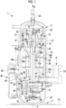
Fig. 1 is a longitudinal cross-sectional view of a compressor according to an embodiment of the present disclosure. -
Fig. 2 is a longitudinal cross-sectional view showing a main part of the compressor ofFig. 1 . -
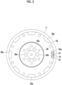
Fig. 3 is a cross-sectional view taken along cutting line III-III ofFig. 2 . -
Fig. 4 is a cross-sectional view taken along cutting line IV-IV ofFig. 2 . -
Fig. 5 is an enlarged view of a portion A inFig. 2 . -
Fig. 6 is a front view of a lower end of an oil return pipe shown inFig. 5 as seen from an inside of a housing. -
Fig. 7 is a transverse cross-sectional view at the lower end of the oil return pipe shown inFig. 5 . -
Fig. 8 is a longitudinal cross-sectional view showing a compressor in an enlarged manner at a height position of the lower end of the oil return pipe. -
Fig. 9 is a transverse cross-sectional view of a stabilizing plate as seen from below. -
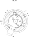
Fig. 10 is a transverse cross-sectional view of the stabilizing plate as seen from above. -
Fig. 11 is a longitudinal cross-sectional view showing a main part of a compressor according to a modification example. -
Fig. 12 is an enlarged view of a portion B inFig. 11 . -
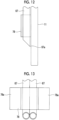
Fig. 13 is a front view of the lower end of the oil return pipe shown inFig. 12 as seen from the inside of the housing. -
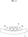
Fig. 14 is a transverse cross-sectional view at the lower end of the oil return pipe shown inFig. 12 . Description of Embodiments - Hereinafter, an embodiment according to the present disclosure will be described with reference to the drawings.
- As shown in
Fig. 1 , acompressor 1 is used for an air conditioner and compresses a refrigerant R, which is, for example, a gas such as carbon dioxide, in two stages. Thecompressor 1 is fixed to an installation surface FL via leg portions 3. Thecompressor 1 includes ahousing 11 and includes a rotary compression mechanism (low-stage-side compression mechanism) 12, a scroll compression mechanism (high-stage-side compression mechanism) 13, anelectric motor 14, and a rotary shaft (rotary shaft portion) 15, which are provided inside thehousing 11. - The
housing 11 has amain body portion 21 having a cylindrical shape, and anupper cover portion 22 and alower cover portion 23 that close upper and lower openings of themain body portion 21. The inside of thehousing 11 forms a sealed space. - The
rotary shaft 15 is provided to extend vertically along an axis X inside thehousing 11. An upper end (one end) side of therotary shaft 15 is rotatably supported by an upper bearing 31. A lower end (other end) side of therotary shaft 15 is rotatably supported by alower bearing 32. - The
electric motor 14 is disposed at a center of therotary shaft 15 in a longitudinal direction and on an outer peripheral side of therotary shaft 15, and rotates therotary shaft 15 around the axis X. Theelectric motor 14 includes arotor 38 fixed to an outer peripheral surface of therotary shaft 15, and astator 39 that faces therotor 38 in a radial direction with a gap from an outer peripheral surface of therotor 38 and that is fixed to an inner wall of themain body portion 21 of thehousing 11 by shrink fitting or the like. - The
rotor 38 is provided withrotor passages 38a provided at a predetermined interval in a circumferential direction. Eachrotor passage 38a penetrates therotor 38 in a vertical direction (axis X direction). The refrigerant discharged from arotary compression mechanism 12 flows upward through therotor passages 38a. Anoil separation plate 38b is fixed to an upper portion of therotor 38. Theoil separation plate 38b has a circular plate shape and is disposed to extend in a horizontal direction. Theoil separation plate 38b rotates around the axis X together with therotor 38. - A plurality of
stator passages 39a are formed in an outer periphery of thestator 39 at a predetermined angular interval in a circumferential direction (specifically, it will be described later with reference toFig. 3 ). - As shown in
Fig. 1 , anupper coil end 39b in which a winding is folded back is located at an upper portion of thestator 39, and alower coil end 39c in which a winding is folded back is located at a lower portion of thestator 39. Theelectric motor 14 is connected to a power source via an inverter (not shown) and rotates therotary shaft 15 with a variable frequency. - The
rotary compression mechanism 12 is provided on the lower end (other end) side of therotary shaft 15 inside thehousing 11. Therotary compression mechanism 12 is a two-cylinder mechanism in the present embodiment, and includes aneccentric shaft portion 41 provided in therotary shaft 15, arotor 42 fixed to theeccentric shaft portion 41 and rotating in a compression chamber C1 eccentrically with respect to the axis X as therotary shaft 15 rotates, and acylinder 44 in which the compression chamber C1 is formed. - The refrigerant R is supplied to the compression chamber C1 formed in the
cylinder 44 from asuction pipe 33. The refrigerant compressed in the compression chamber C1 is discharged from arotary discharge pipe 43 to a region below theelectric motor 14 in thehousing 11 via thelower bearing 32. - The
cylinder 44 is fixed to thelower bearing 32 from below by abolt 48. Anoil pump 49 fixed by thebolt 48 together with thecylinder 44 is provided below thecylinder 44. The oil is sucked from an oil reservoir O1 in a lower portion of thehousing 11 by theoil pump 49, and is guided to the upper bearing 31 side through anoil supply hole 15a penetrating therotary shaft 15 along the axis X. - A
scroll compression mechanism 13 is disposed above theelectric motor 14 inside thehousing 11. Thescroll compression mechanism 13 includes afixed scroll 51 fixed to theupper bearing 31, and anorbiting scroll 57 disposed below thefixed scroll 51 to face thefixed scroll 51. - The
fixed scroll 51 has anend plate 52 fixed to an upper surface of theupper bearing 31 and a fixedwrap 53 protruding downward from theend plate 52. Adischarge hole 52a vertically penetrating theend plate 52 is formed in a central portion (vicinity of the axis X) of theend plate 52. - The orbiting
scroll 57 is disposed to be interposed between the upper bearing 31 and thefixed scroll 51. The orbitingscroll 57 has anend plate 58 connected to an upper end side of therotary shaft 15 and anorbiting wrap 59 protruding upward from theend plate 58. - The
end plate 58 is fixed to theeccentric shaft portion 56 provided at the upper end of therotary shaft 15 via abush 55, and rotates eccentrically with respect to the axis X as therotary shaft 15 rotates. - The orbiting wrap 59 forms a compression chamber C2 for compressing the refrigerant R between the orbiting
wrap 59 and the fixedwrap 53 by meshing with the fixedwrap 53. - A
balance weight chamber 63 is formed between a recessed portion on a central side of theupper bearing 31 and a lower side of the orbitingscroll 57. In thebalance weight chamber 63, abalance weight 54 rotates together with therotary shaft 15. - The refrigerant R compressed by the
rotary compression mechanism 12 and discharged into thehousing 11 is sucked into the compression chamber C2 from an outer peripheral side of thescroll compression mechanism 13 and is compressed toward a center side. The compressed refrigerant R is discharged from adischarge pipe 34 to the outside of thehousing 11 via thedischarge hole 52a of the fixedscroll 51. - A
cover 45 is provided below theupper bearing 31 so as to cover theupper bearing 31. Thecover 45 is formed by sheet metal processing, and has a substantially conical shape that is expanded in diameter from the lower side to the upper side. Asuction opening 45a is provided at a lower end of thecover 45. That is, thesuction opening 45a faces downward and is an annular region formed between thecover 45 and therotary shaft 15. A space below thehousing 11 and a space on theupper bearing 31 side are partitioned by thecover 45, and only the refrigerant sucked from thesuction opening 45a is guided to thescroll compression mechanism 13. - An
oil level tank 60 is provided outside and below thehousing 11. Theoil level tank 60 is a hollow container and communicates with the inside of thehousing 11 via alower pipe 61 and an upperpressure equalization pipe 62. Theoil level tank 60 measures an oil level of the oil reservoir O1 by guiding the oil from the oil reservoir O1 in thehousing 11 via thelower pipe 61. - A downstream end of an oil separator
oil return pipe 65 is connected to a lower side portion of thehousing 11. An upstream end of the oil separatoroil return pipe 65 is connected to an oil separator (not shown). The oil separated by the oil separator from the refrigerant discharged from thecompressor 1 is returned to the oil reservoir O1 in thehousing 11 via the oil separatoroil return pipe 65. A height position where the downstream end of the oil separatoroil return pipe 65 is connected to thehousing 11 is below thelower bearing 32. - An
oil return pipe 67 that is in contact with an inner wall of thehousing 11 and extends in a vertical direction is provided in thehousing 11. As shown inFig. 2 , an upper end (one end) of theoil return pipe 67 is fixed to theupper bearing 31, and a lower end (other end) is provided to be located in the oil reservoir O1 in the lower portion of thehousing 11. - The
oil return pipe 67 is provided to penetrate a space formed between thestator 39 and thehousing 11. Specifically, as shown inFig. 3 , cutouts are provided in the outer periphery of thestator 39 in a circumferential direction at a predetermined angular interval so that the plurality ofstator passages 39a are formed with the inner wall of thehousing 11. The refrigerant or the oil flows through thestator passages 39a. Theoil return pipe 67 is inserted through one or a plurality of thestator passages 39a. In an example shown inFig. 3 , theoil return pipe 67 is inserted through one of thestator passages 39a. - As can be seen from
Fig. 3 , therotor passages 38a are provided at a predetermined interval in the circumferential direction. The refrigerant discharged from arotary compression mechanism 12 flows upward through therotor passages 38a. - As can be seen from
Fig. 3 , twooil return pipes 67 are provided in parallel. That is, the twooil return pipes 67 are provided in parallel such that longitudinal axes thereof are parallel to each other. Each of theoil return pipes 67 is made of, for example, a copper pipe, and has the same outer diameter and the same inner diameter in the length direction. The number of theoil return pipes 67 provided in parallel is determined by an amount of the oil to be returned, and can be three or more. - As shown in
Fig. 2 , an upper end of theoil return pipe 67 is attached to communicate with anoil return hole 31a formed in theupper bearing 31. Theoil return hole 31a extends in a horizontal direction and is formed such that an inner periphery-side end portion thereof is open to thebalance weight chamber 63 that accommodates thebalance weight 54. -
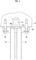
Fig. 4 is a cross-sectional view taken along cutting line IV-IV ofFig. 2 , in which a fixing portion between theoil return pipe 67 and theupper bearing 31 is shown. The upper end of each of the twooil return pipes 67 is fixed to acommon boss 68. Theboss 68 is made of metal, into which the upper end of eachoil return pipe 67 is inserted and fixed by brazing or the like. The upper end of eachoil return pipe 67 communicates with acommunication hole 68a formed in theboss 68. Thecommunication hole 68a is open toward an upper surface of theboss 68. Theboss 68 is fixed to a lower surface of theupper bearing 31 by a plurality ofbolts 69. Thecommunication hole 68a formed in theboss 68 is open to avertical hole 31b connected to theoil return hole 31a of theupper bearing 31 so that theoil return pipe 67 and thebalance weight chamber 63 communicate with each other. -
Fig. 5 is an enlarged view of a portion A ofFig. 2 , in which a lower end of theoil return pipe 67 is shown. The lower end of theoil return pipe 67 is fixed to the inner wall of thehousing 11 via a rod-shapedmember 70. The rod-shapedmember 70 is made of steel and is a solid round bar. A length of the rod-shapedmember 70 overlaps a predetermined dimension (for example, several mm to several tens of mm) of a tip of theoil return pipe 67 and protrudes downward from the tip of theoil return pipe 67 in a range of a predetermined dimension (for example, several mm to several tens of mm). - As shown in
Figs. 6 and 7 , the rod-shapedmember 70 is fixed to each of side surfaces of lower ends of the rod-shapedmembers 70 on both sides adjacent to each other. The fixing between the rod-shapedmember 70 and theoil return pipe 67 is performed by, for example, brazing. An outer diameter of the rod-shapedmember 70 may be any size as long as the rod-shapedmember 70 can be inserted between theoil return pipes 67 and can be fixed to each of theoil return pipes 67, and is preferably smaller than the outer diameter of theoil return pipe 67. A cross-sectional shape of the rod-shapedmember 70 may be circular as shown inFig. 7 , or may be a polygon. - The rod-shaped
member 70 is fixed to the inner wall of thehousing 11. Specifically, the lower end (tip) of the rod-shapedmember 70 is fixed by welding. For example, before the lower cover portion 23 (refer toFig. 1 ) of thehousing 11 is attached, the lower end of the rod-shapedmember 70 is welded by accessing from below themain body portion 21. The lower end of the rod-shapedmember 70 is fixed to the inner wall of thehousing 11, so that theoil return pipe 67 is in a state of being close to the inner wall of thehousing 11 over substantially the entire oil return pipe 67 (for example, 1/2 or more of a longitudinal dimension from the lower end of the oil return pipe 67) . For example, as shown inFig. 1 , theoil return pipe 67 is subjected to bending between a fixing position of the upper end of theoil return pipe 67 and a height position of theupper coil end 39b of theelectric motor 14, and theoil return pipe 67 is brought close to the inner wall of thehousing 11 from the height position of theupper coil end 39b over the entire lower side. Accordingly, the movement of theoil return pipe 67 is restricted, and the generation of vibration of theoil return pipe 67 can be suppressed. It is preferable that theoil return pipe 67 is brought into contact with the inner wall of thehousing 11. However, a slight gap (for example, 0.1 mm to several mm) may be formed as long as the movement of theoil return pipe 67 during vibration can be restricted. - As shown in
Fig. 5 , the lower end of the rod-shapedmember 70 has a tapered shape cut at one surface inclined with respect to the longitudinal axis of theoil return pipe 67. Then, atip 67a of theoil return pipe 67 having a tapered shape is located on an inner wall side of thehousing 11. Accordingly, when theoil return pipe 67 is inserted along the inner wall of thehousing 11 during fabrication, the sharpenedtip 67a is advanced along the inner wall, so that theoil return pipe 67 can be smoothly inserted while avoiding interference with other members (for example, thestator 39 or the like) in the housing. - As shown in
Fig. 8 , a stabilizing plate (oil surface upper plate) 75 is fixed to a lower surface of thelower bearing 32. The stabilizingplate 75 is fixed to the lower bearing 32 (specifically, a leg portion protruding in a radial direction of the lower bearing 32) by abolt 76. As shown inFigs. 9 and10 , the stabilizingplate 75 is a circular plate in which an opening is formed at the center. The stabilizingplate 75 can cover an upper side of an oil surface of the oil reservoir O1 (refer toFigs. 1 and2 ). However, a height position of the stabilizingplate 75 may be lower than a refrigerant discharge position of therotary compression mechanism 12. In addition, a fixing position of the stabilizingplate 75 is not limited to thelower bearing 32, and may be fixed to another fixing position (for example, the housing 11). The stabilizingplate 75 can stabilize the oil surface of the oil reservoir O1, and can prevent the oil from separating from the oil reservoir O1 as much as possible due to the flow of the refrigerant discharged from therotary compression mechanism 12. - In
Fig. 9 , one set of twooil return pipes 67 are provided at each of three locations in the circumferential direction. However, this is an example, and one set of theoil return pipes 67 may be provided at one location as inFig. 10 orFig. 3 . - As shown in
Fig. 8 , the lower end of theoil return pipe 67 is located below the stabilizingplate 75. By partitioning an opening of the lower end of theoil return pipe 67 from a discharge side of therotary compression mechanism 12 in this way, even when the oil returned from theoil return pipe 67 splashes on the oil surface of the oil reservoir O1, the oil can be prevented from being rolled up in association with the flow of the discharged refrigerant of therotary compression mechanism 12. - The lower end of the
oil return pipe 67 is provided below a position where the downstream end of the oil separatoroil return pipe 65 is open into thehousing 11. In this way, the oil separatoroil return pipe 65 is opened below the stabilizingplate 75. Accordingly, even when the oil returned from the oil separatoroil return pipe 65 flows in as indicated by a black arrow (refer toFig. 8 ), and the oil splashes on the oil surface of the oil reservoir O1 to disturb the oil surface, the oil can be prevented from being rolled up in association with the flow of the discharged refrigerant of therotary compression mechanism 12. - The
compressor 1 having the above-described configuration operates as follows. - The refrigerant evaporated in an evaporator (not shown) is sucked into the
compressor 1 from thesuction pipe 33 and is compressed by therotary compression mechanism 12. The refrigerant compressed by therotary compression mechanism 12 is discharged from therotary discharge pipe 43 into thehousing 11. - The refrigerant discharged into the
housing 11 is sucked from thesuction opening 45a of thecover 45, and is guided to thescroll compression mechanism 13 through a flow path in thecover 45 to be compressed. The refrigerant compressed by thescroll compression mechanism 13 is discharged from thedischarge pipe 34 to an external gas cooler or condenser through thedischarge hole 52a of the fixedscroll 51. - The oil is separated from the refrigerant discharged from the
discharge pipe 34 by an oil separator (not shown). The separated oil is returned to thehousing 11 through the oil separatoroil return pipe 65, and is stored in the oil reservoir O1. - The oil stored in the oil reservoir O1 is sucked up by the
oil pump 49, and is guided to thescroll compression mechanism 13 side through theoil supply hole 15a formed in therotary shaft 15. The oil guided to thescroll compression mechanism 13 side is returned to the oil reservoir O1 on the lower side after lubricating a sliding portion such as a bearing portion of theupper bearing 31 and thebush 55. The oil after lubrication, which is guided to thebalance weight chamber 63, is guided to theoil return pipe 67 through theoil return hole 31a and thevertical hole 31b (refer toFig. 2 ) formed in theupper bearing 31. - The oil guided to the
oil return pipe 67 is discharged from the lower end through a flow path inside theoil return pipe 67, and is returned to the oil reservoir O1. - According to the present embodiment, the following operations and effects are achieved.
- The oil that has lubricated the
upper bearing 31 is returned to the oil reservoir O1 in the lower portion of thehousing 11 by theoil return pipe 67. Since the upper end of theoil return pipe 67 is a fixed end fixed to theupper bearing 31, there is a possibility that the vibration of thecompressor 1 is transmitted and repeated stress is generated. In the present embodiment, the overall rigidity of theoil return pipes 67 is increased by bundling a plurality ofoil return pipes 67 provided in parallel such that the longitudinal axes thereof are parallel to each other via the rod-shapedmember 70. Accordingly, the vibration of theoil return pipe 67 can be suppressed. In addition, since a strength of the upper end of theoil return pipe 67 fixed to theupper bearing 31 can be increased by increasing a cross-sectional secondary moment with the plurality ofoil return pipes 67, fatigue breakage at the upper end of theoil return pipe 67 can be suppressed. - The lower end of the
oil return pipe 67 is fixed to the inner wall of thehousing 11 by using the rod-shapedmember 70. Accordingly, two points of the upper end and the lower end of theoil return pipe 67 are fixed, so that the vibration of theoil return pipe 67 can be further suppressed. - Both
oil return pipes 67 are bundled by fixing the rod-shapedmember 70 to each of the side surfaces of the lower ends of theoil return pipes 67 adjacent to each other. Then, the rod-shapedmember 70 is fixed to the inner wall of thehousing 11. Accordingly, theoil return pipes 67 adjacent to each other can be easily fixed to the inner wall of thehousing 11 after being bundled. - In the above-described embodiment, the rod-shaped
member 70 is used when the lower ends of theoil return pipes 67 are bundled and fixed, but the configuration can be modified as follows. - As shown in
Figs. 11 to 14 , the lower ends of theoil return pipes 67 are bundled and fixed by using a fixingbracket 78. The fixingbracket 78 can be formed by bending a flat plate. Specifically, as shown inFig. 14 , the flat plate is bent so as to form a space with the inner wall of thehousing 11. Then,leg portions 78a on both sides of the fixingbracket 78 are fixed to thehousing 11 by welding or the like. The lower end of theoil return pipe 67 is inserted into the space formed by the fixingbracket 78. The displacement of each of theoil return pipes 67 is constrained in the space formed by the fixingbracket 78. Accordingly, the lower ends of theoil return pipes 67 can be easily bundled and positioned. - The compressor described in the embodiments described above is understood as follows, for example.
- A compressor according to an aspect of the present disclosure includes: a rotary shaft portion (15) that is rotationally driven; a compression mechanism (13) that is connected to one end of the rotary shaft portion and compresses a refrigerant; a bearing portion (31) that supports the rotary shaft portion; a housing (11) that accommodates the rotary shaft portion, the compression mechanism, and the bearing portion and has an oil reservoir (O1) in a lower portion; and an oil return pipe (67) that is provided in the housing and has one end fixed to the bearing portion and the other end extending toward the oil reservoir such that oil held in the bearing portion is returned to the oil reservoir, in which a plurality of the oil return pipes are provided in parallel such that longitudinal axes thereof are parallel to each other, and the oil return pipes are bundled.
- The oil that has lubricated the bearing portion is temporarily held in the bearing portion and is returned to the oil reservoir in the lower portion of the housing by the oil return pipe. Since one end of the oil return pipe is a fixed end fixed to the bearing portion, the vibration of the compressor is transmitted and repeated stress is generated.
- The overall rigidity of the oil return pipes can be increased by bundling the plurality of oil return pipes provided in parallel such that the longitudinal axes thereof are parallel to each other. Accordingly, the vibration of the oil return pipe can be suppressed. In addition, since a strength of one end of the oil return pipe fixed to the bearing portion can be increased by increasing a cross-sectional secondary moment with the plurality of oil return pipes, fatigue breakage at the one end of the oil return pipe can be suppressed.
- For example, a scroll compression mechanism is used as the compression mechanism.
- In the compressor according to the aspect of the present disclosure, the other end of the oil return pipe is fixed to an inner wall of the housing.
- The other end of the oil return pipe is fixed to the inner wall of the housing. Accordingly, two points of the one end and the other end of the oil return pipe are fixed, so that the vibration of the oil return pipe can be further suppressed.
- The compressor according to the aspect of the present disclosure further includes a rod-shaped member (70) that is provided between the other ends of the oil return pipes adjacent to each other and is fixed to each of side surfaces of the other ends adjacent to each other, in which the rod-shaped member is fixed to the inner wall of the housing.
- Both oil return pipes are bundled by fixing the rod-shaped member to each of the side surfaces of the other ends of the oil return pipes adjacent to each other. Then, the rod-shaped member is fixed to the inner wall of the housing. Accordingly, the oil return pipes adjacent to each other can be easily fixed to the inner wall of the housing after being bundled.
- The fixing of the rod-shaped member and the oil return pipe and/or the fixing of the rod-shaped member and the inner wall of the housing can be performed by, for example, brazing or welding.
- The compressor according to the aspect of the present disclosure further includes a fixing bracket (78) that is fixed to the inner wall of the housing and forms a space with the inner wall, in which the other ends of the plurality of oil return pipes are bundled in a state of being inserted into the space.
- The fixing bracket is fixed to the inner wall of the housing, and a space is formed between the inner wall and the fixing bracket. Then, the other ends of the plurality of oil return pipes are inserted into the space to bundle the oil return pipes. As a result, the other ends of the oil return pipes can be easily bundled.
- In the compressor according to the aspect of the present disclosure, the oil return pipe is installed in a state of being close to the inner wall of the housing over 1/2 or more of a length in a longitudinal direction from the other end.
- The oil return pipe is disposed in a state of being close to the inner wall of the housing over 1/2 or more of a length in the longitudinal direction from the other end of the oil return pipe. Accordingly, the movement of the oil return pipe is restricted, and the generation of vibration of the oil return pipe can be suppressed.
- The close means that the oil return pipe and the inner wall of the housing may be in contact with each other or may be separated by a gap of, for example, about 0.1 mm to several mm.
- In the compressor according to the aspect of the present disclosure, the oil return pipe has the same diameter in the longitudinal direction thereof.
- Since the oil return pipe can be fabricated using the pipe having the same diameter, it is possible to reduce the cost.
- In the compressor according to an aspect of the present disclosure, the other end of the oil return pipe has a tapered shape cut at one surface inclined with respect to a longitudinal axis of the oil return pipe, and a tip (67a) of the tapered shape is located on an inner wall side of the housing.
- The other end of the oil return pipe has a tapered shape cut at one surface inclined with respect to the longitudinal axis, and the tip thereof is located on the inner wall side of the housing. Accordingly, when the oil return pipe is inserted along the inner wall of the housing, the sharpened tip is advanced along the inner wall, so that the oil return pipe can be smoothly inserted while avoiding interference with other members in the housing.
- The compressor according to the aspect of the present disclosure is the compressor according to any one of
Claims 1 to 7 further including: another compression mechanism (12) that is connected to the other end of the rotary shaft portion and compresses a refrigerant; and an oil surface upper plate (75) that is provided below a refrigerant discharge position of the other compression mechanism and above an oil surface formed in the oil reservoir to cover the oil surface. - The oil surface upper plate that covers the oil surface is provided below a refrigerant discharge position of another compression mechanism connected to the other end of the rotary shaft portion. Further, the oil surface upper plate is provided above the oil surface formed in the oil reservoir. In this manner, it is possible to prevent the oil from being separated from the oil reservoir as much as possible due to the flow of the refrigerant discharged from the other compression mechanism.
- As another compression mechanism, for example, a rotary compression mechanism is used.
- In the compressor according to the aspect of the present disclosure, the other end of the oil return pipe is open below the oil surface upper plate.
- Since the other end of the oil return pipe is open below the oil surface upper plate, even when the oil returned from the oil return pipe splashes on the oil surface, the oil can be prevented from flowing in association with the flow of the discharged refrigerant of the other compression mechanism by the oil surface upper plate.
- The compressor according to the aspect of the present disclosure further includes an oil separator oil return pipe (65) that returns oil from an oil separator that stores the oil separated from the refrigerant discharged from the compressor, in which the oil separator oil return pipe is open below the oil surface upper plate.
- Since the oil separator oil return pipe is open below the oil surface upper plate, even when the oil returned from the oil separator oil return pipe splashes on the oil surface, the oil can be isolated from the flow of the discharged refrigerant of the other compression mechanism by the oil surface upper plate.
-
- 1: compressor
- 3: leg portion
- 11: housing
- 12: rotary compression mechanism (low-stage-side compression mechanism)
- 13: scroll compression mechanism (high-stage-side compression mechanism)
- 14: electric motor
- 15: rotary shaft (rotary shaft portion)
- 15a: oil supply hole
- 21: main body portion
- 22: upper cover portion
- 23: lower cover portion
- 31: upper bearing (bearing portion)
- 31a: oil return hole
- 31b: vertical hole
- 32: lower bearing
- 33: suction pipe
- 34: discharge pipe
- 38: rotor
- 38a: rotor passage
- 38b: oil separation plate
- 39: stator
- 39a: stator passage
- 39b: upper coil end
- 39c: lower coil end
- 41: eccentric shaft portion
- 42: rotor
- 43: rotary discharge pipe
- 44: cylinder
- 45: cover
- 45a: suction opening
- 48: bolt
- 49: oil pump
- 51: fixed scroll
- 52: end plate
- 52a: discharge hole
- 53: fixed wrap
- 54: balance weight
- 55: bush
- 56: eccentric shaft portion
- 57: orbiting scroll
- 58: end plate
- 59: orbiting wrap
- 60: oil level tank
- 61: lower pipe
- 62: pressure equalization pipe
- 63: balance weight chamber
- 65: oil separator oil return pipe
- 67: oil return pipe
- 67a: tip
- 68: boss
- 68a: communication hole
- 69: bolt
- 70: rod-shaped member
- 75: stabilizing plate (oil surface upper plate)
- 76: bolt
- 78: fixing bracket
- 78a: leg portion
- C1: compression chamber
- C2: compression chamber
- FL: installation surface
- O1: oil reservoir
- X: axis
Claims (10)
- A compressor comprising:a rotary shaft portion that is rotationally driven;a compression mechanism that is connected to one end of the rotary shaft portion and compresses a refrigerant;a bearing portion that supports the rotary shaft portion;a housing that accommodates the rotary shaft portion, the compression mechanism, and the bearing portion and has an oil reservoir in a lower portion; andan oil return pipe that is provided in the housing and has one end fixed to the bearing portion and the other end extending toward the oil reservoir such that oil held in the bearing portion is returned to the oil reservoir,wherein a plurality of the oil return pipes are provided in parallel such that longitudinal axes thereof are parallel to each other, and the oil return pipes are bundled.
- The compressor according to Claim 1, wherein the other end of the oil return pipe is fixed to an inner wall of the housing.
- The compressor according to Claim 2, further comprising a rod-shaped member that is provided between the other ends of the oil return pipes adjacent to each other and is fixed to each of side surfaces of the other ends adjacent to each other,
wherein the rod-shaped member is fixed to the inner wall of the housing. - The compressor according to Claim 2, further comprising a fixing bracket that is fixed to the inner wall of the housing and forms a space with the inner wall,
wherein the other ends of the plurality of oil return pipes are bundled in a state of being inserted into the space. - The compressor according to any one of Claims 1 to 4,
wherein the oil return pipe is installed in a state of being close to the inner wall of the housing over 1/2 or more of a length in a longitudinal direction from the other end. - The compressor according to any one of Claims 1 to 5, wherein the oil return pipe has the same diameter in a longitudinal direction thereof.
- The compressor according to any one of Claims 1 to 6, wherein the other end of the oil return pipe has a tapered shape cut at one surface inclined with respect to a longitudinal axis of the oil return pipe, and
a tip of the tapered shape is located on an inner wall side of the housing. - The compressor according to any one of Claims 1 to 7, further comprising:another compression mechanism that is connected to the other end of the rotary shaft portion and compresses a refrigerant; andan oil surface upper plate that is provided below a refrigerant discharge position of the other compression mechanism and above an oil surface formed in the oil reservoir to cover the oil surface.
- The compressor according to Claim 8,
wherein the other end of the oil return pipe is open below the oil surface upper plate. - The compressor according to Claim 8 or 9, further comprising an oil separator oil return pipe that returns oil from an oil separator that stores the oil separated from the refrigerant discharged from the compressor,
wherein the oil separator oil return pipe is open below the oil surface upper plate.
Applications Claiming Priority (2)
| Application Number | Priority Date | Filing Date | Title |
|---|---|---|---|
| JP2021189461A JP7830084B2 (en) | 2021-11-22 | 2021-11-22 | compressor |
| PCT/JP2022/040827 WO2023090149A1 (en) | 2021-11-22 | 2022-10-31 | Compressor |
Publications (4)
| Publication Number | Publication Date |
|---|---|
| EP4400724A1 true EP4400724A1 (en) | 2024-07-17 |
| EP4400724A4 EP4400724A4 (en) | 2024-12-18 |
| EP4400724C0 EP4400724C0 (en) | 2026-03-11 |
| EP4400724B1 EP4400724B1 (en) | 2026-03-11 |
Family
ID=86396796
Family Applications (1)
| Application Number | Title | Priority Date | Filing Date |
|---|---|---|---|
| EP22895432.7A Active EP4400724B1 (en) | 2021-11-22 | 2022-10-31 | Compressor |
Country Status (3)
| Country | Link |
|---|---|
| EP (1) | EP4400724B1 (en) |
| JP (1) | JP7830084B2 (en) |
| WO (1) | WO2023090149A1 (en) |
Family Cites Families (7)
| Publication number | Priority date | Publication date | Assignee | Title |
|---|---|---|---|---|
| JP4192158B2 (en) * | 2005-03-24 | 2008-12-03 | 日立アプライアンス株式会社 | Hermetic scroll compressor and refrigeration air conditioner |
| JP2009097486A (en) * | 2007-10-19 | 2009-05-07 | Mitsubishi Heavy Ind Ltd | Compressor |
| JP5701112B2 (en) * | 2011-03-15 | 2015-04-15 | 三菱重工業株式会社 | Hermetic compressor |
| JP5695187B2 (en) * | 2011-04-25 | 2015-04-01 | 株式会社日立製作所 | Refrigerant compressor and refrigeration cycle apparatus using the same |
| JP6812230B2 (en) | 2016-12-19 | 2021-01-13 | 日立ジョンソンコントロールズ空調株式会社 | Compressor |
| JP6896569B2 (en) * | 2017-08-29 | 2021-06-30 | 三菱重工サーマルシステムズ株式会社 | Scroll compressor and its control method and air conditioner |
| CN113396283B (en) * | 2019-01-28 | 2022-12-16 | 三菱电机株式会社 | scroll compressor |
-
2021
- 2021-11-22 JP JP2021189461A patent/JP7830084B2/en active Active
-
2022
- 2022-10-31 EP EP22895432.7A patent/EP4400724B1/en active Active
- 2022-10-31 WO PCT/JP2022/040827 patent/WO2023090149A1/en not_active Ceased
Also Published As
| Publication number | Publication date |
|---|---|
| JP2023076186A (en) | 2023-06-01 |
| JP7830084B2 (en) | 2026-03-16 |
| EP4400724C0 (en) | 2026-03-11 |
| EP4400724B1 (en) | 2026-03-11 |
| WO2023090149A1 (en) | 2023-05-25 |
| EP4400724A4 (en) | 2024-12-18 |
Similar Documents
| Publication | Publication Date | Title |
|---|---|---|
| EP3401543A1 (en) | Scroll compressor with oil separation | |
| EP2733306B1 (en) | Compressor having rotary compression mechanism with a muffler cover | |
| JPS61118576A (en) | Rotary compressor and method of sealing suction pipe thereof | |
| EP4400724B1 (en) | Compressor | |
| EP0965760B1 (en) | Hermetic compressor lubrication system | |
| EP3922854A1 (en) | Rotary compressor, method for manufacturing rotary compressor, and refrigeration cycle device | |
| WO2022085443A1 (en) | Compressor and refrigeration cycle device | |
| EP4400716B1 (en) | Compressor | |
| EP4400722B1 (en) | Compressor | |
| EP4400721A1 (en) | Compressor | |
| EP2960513B1 (en) | Hermetic compressor | |
| EP4621241A1 (en) | Compressor | |
| JP4315339B2 (en) | Scroll fluid machinery | |
| KR20100011804A (en) | Motor and compressor with it | |
| EP4621236A1 (en) | Compressor and assembly method for same | |
| KR20090012867A (en) | Rotary two stage compressor | |
| JP5540577B2 (en) | Scroll compressor | |
| EP4621240A1 (en) | Balance weight and compressor provided with same | |
| EP4621242A1 (en) | Compressor | |
| JP2006177158A (en) | Hermetic electric compressor and refrigeration cycle apparatus | |
| JP2024076714A (en) | Compressor and method for assembling same | |
| JP2019015235A (en) | Rolling cylinder type displacement compressor | |
| JP2025152787A (en) | Compressor | |
| JP2006104958A (en) | Scroll compressor | |
| JPH11107952A (en) | Fluid machine |
Legal Events
| Date | Code | Title | Description |
|---|---|---|---|
| STAA | Information on the status of an ep patent application or granted ep patent |
Free format text: STATUS: THE INTERNATIONAL PUBLICATION HAS BEEN MADE |
|
| PUAI | Public reference made under article 153(3) epc to a published international application that has entered the european phase |
Free format text: ORIGINAL CODE: 0009012 |
|
| STAA | Information on the status of an ep patent application or granted ep patent |
Free format text: STATUS: REQUEST FOR EXAMINATION WAS MADE |
|
| 17P | Request for examination filed |
Effective date: 20240408 |
|
| AK | Designated contracting states |
Kind code of ref document: A1 Designated state(s): AL AT BE BG CH CY CZ DE DK EE ES FI FR GB GR HR HU IE IS IT LI LT LU LV MC ME MK MT NL NO PL PT RO RS SE SI SK SM TR |
|
| A4 | Supplementary search report drawn up and despatched |
Effective date: 20241115 |
|
| RIC1 | Information provided on ipc code assigned before grant |
Ipc: F04C 18/02 20060101ALI20241111BHEP Ipc: F04C 23/00 20060101ALI20241111BHEP Ipc: F04B 39/02 20060101ALI20241111BHEP Ipc: F04C 29/02 20060101AFI20241111BHEP |
|
| DAV | Request for validation of the european patent (deleted) | ||
| DAX | Request for extension of the european patent (deleted) | ||
| GRAP | Despatch of communication of intention to grant a patent |
Free format text: ORIGINAL CODE: EPIDOSNIGR1 |
|
| STAA | Information on the status of an ep patent application or granted ep patent |
Free format text: STATUS: GRANT OF PATENT IS INTENDED |
|
| RIC1 | Information provided on ipc code assigned before grant |
Ipc: F04C 29/02 20060101AFI20250911BHEP Ipc: F04B 39/02 20060101ALI20250911BHEP Ipc: F04C 23/00 20060101ALI20250911BHEP Ipc: F04C 18/02 20060101ALI20250911BHEP |
|
| INTG | Intention to grant announced |
Effective date: 20251002 |
|
| GRAS | Grant fee paid |
Free format text: ORIGINAL CODE: EPIDOSNIGR3 |
|
| GRAA | (expected) grant |
Free format text: ORIGINAL CODE: 0009210 |
|
| STAA | Information on the status of an ep patent application or granted ep patent |
Free format text: STATUS: THE PATENT HAS BEEN GRANTED |
|
| AK | Designated contracting states |
Kind code of ref document: B1 Designated state(s): AL AT BE BG CH CY CZ DE DK EE ES FI FR GB GR HR HU IE IS IT LI LT LU LV MC ME MK MT NL NO PL PT RO RS SE SI SK SM TR |
|
| REG | Reference to a national code |
Ref country code: CH Ref legal event code: F10 Free format text: ST27 STATUS EVENT CODE: U-0-0-F10-F00 (AS PROVIDED BY THE NATIONAL OFFICE) Effective date: 20260311 Ref country code: GB Ref legal event code: FG4D |
|
| REG | Reference to a national code |
Ref country code: IE Ref legal event code: FG4D |
|
| U01 | Request for unitary effect filed |
Effective date: 20260316 |
|
| U07 | Unitary effect registered |
Designated state(s): AT BE BG DE DK EE FI FR IT LT LU LV MT NL PT RO SE SI Effective date: 20260320 |
|
| PG25 | Lapsed in a contracting state [announced via postgrant information from national office to epo] |
Ref country code: RS Free format text: LAPSE BECAUSE OF FAILURE TO SUBMIT A TRANSLATION OF THE DESCRIPTION OR TO PAY THE FEE WITHIN THE PRESCRIBED TIME-LIMIT Effective date: 20260611 |
|
| PG25 | Lapsed in a contracting state [announced via postgrant information from national office to epo] |
Ref country code: ES Free format text: LAPSE BECAUSE OF FAILURE TO SUBMIT A TRANSLATION OF THE DESCRIPTION OR TO PAY THE FEE WITHIN THE PRESCRIBED TIME-LIMIT Effective date: 20260311 |
|
| PG25 | Lapsed in a contracting state [announced via postgrant information from national office to epo] |
Ref country code: GR Free format text: LAPSE BECAUSE OF FAILURE TO SUBMIT A TRANSLATION OF THE DESCRIPTION OR TO PAY THE FEE WITHIN THE PRESCRIBED TIME-LIMIT Effective date: 20260612 |
|
| PG25 | Lapsed in a contracting state [announced via postgrant information from national office to epo] |
Ref country code: NO Free format text: LAPSE BECAUSE OF FAILURE TO SUBMIT A TRANSLATION OF THE DESCRIPTION OR TO PAY THE FEE WITHIN THE PRESCRIBED TIME-LIMIT Effective date: 20260611 |
|
| PG25 | Lapsed in a contracting state [announced via postgrant information from national office to epo] |
Ref country code: HR Free format text: LAPSE BECAUSE OF FAILURE TO SUBMIT A TRANSLATION OF THE DESCRIPTION OR TO PAY THE FEE WITHIN THE PRESCRIBED TIME-LIMIT Effective date: 20260311 |